

Page 1
SIMRAD GS10
GPS Smart Antenna
Introduction
The GS10 GPS Smart Antenna is a self-contained position provider
for a navigation system. The antenna can be mounted in the exposed environment on a ship, and will supply position data, time,
SOG and COG, using NMEA2000 protocols on Simrad’s SimNet databus.
The GS10 contains a 12-parallel channel GPS receiver with WAAS
and EGNOS. It comes with a fixed 5 m (16.4’) SimNet cable with
connector, ready to connect to a Tee Joiner on the SimNet system,
or navigation product.
Installation
This paper informs how to install your GS10 GPS Smart Antenna and
connect it to a NMEA2000/SimNet network using SimNet network
components.
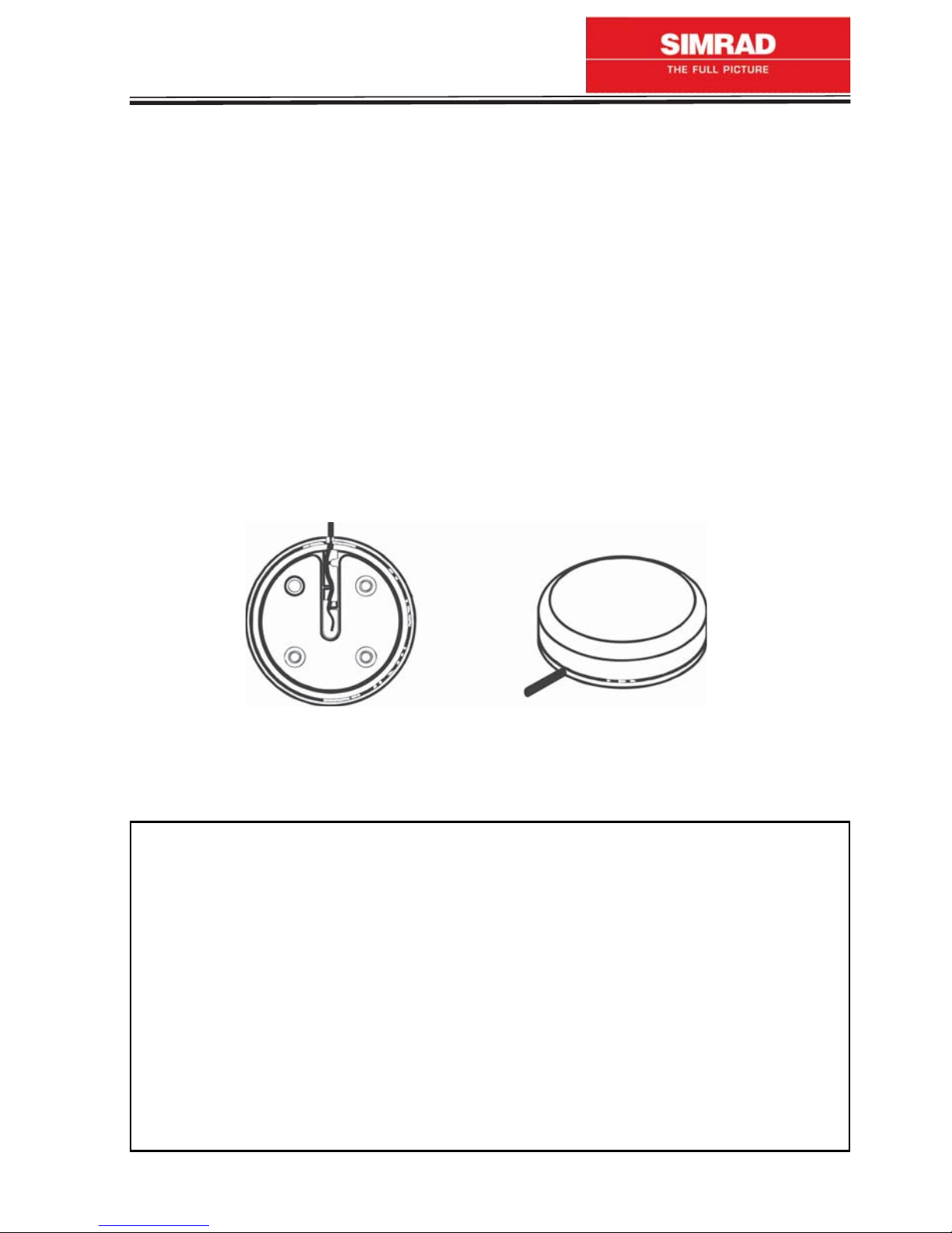
GS10, bottom view (left) and top view (right).
Supplied Parts:
GS10 GPS Smart Antenna incl. 5 m (16.4’) cable w/connector.
Quick release mount adapter incl. 0-ring, 2 long mounting screws,
2 short screws, 2 lock adapters.
Pole mount adapter incl. 4 mounting screws and 4 lock washers.
Tools required:
Wire pliers, flat + cross-shaped screwdriver.
10 mm (3/8”) drill bit (if you need to route the cable through a
bulkhead).
2.5 mm (7/64”) drill bit (for the screw holes, to secure the quick
release mount).
1
Page 2
Mounting location
The GS10 can be mounted on any flat surface (min. 90 mm (3 1/2”
wide). The pole mount adapter lets you mount the antenna on a
pole or swivel mount that uses standard marine 1” - 14 threads. To
determine the mounting location, be sure that a clear, unobstructed
view of the sky is available, as GPS signals travel “line-of-sight” at
very high frequencies and therefore almost anything blocking the
antenna’s view can stop the unit from finding a satellite.
Caution: Do not mount the GS10 antenna in the direct path of a
radar antenna’s beam. Radar radiates high-energy signals that can
interfere with GPS signal reception.
Surface mount
Once you’ve determined the mounting location, use the quick release mount adapter as template to drill 2 holes (2.5 mm (7/64”)
drill bit) for the 2 long mounting screws. Use the 2 screws to secure
the adapter to the surface with “THIS SIDE UP” facing upwards.
If you wish to route the cable through the mounting surface, drill
a 10 mm (3/8”) hole for the cable’s connector. There is a notch in
the antenna housing that allows the cable to pass through, instead
of routing it through the mounting surface. Pass the O-ring over
the cable and press it into the groove on the bottom of the antenna housing. If you are using the housing notch to route the cable
outside, you may need to cut a notch in the O-ring for a proper fit.
Apply a little silicone grease to the O-ring when ready to attach the
antenna to the quick release mount adapter.
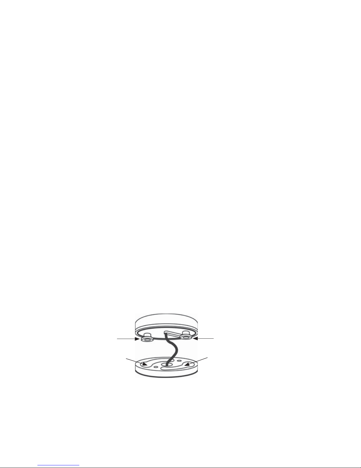
GS10 Antenna
Lock adapter Lock adapter
Curved keyhole Curved keyhole
GS10 Quick release mount
Fix the 2 lock adapters with the 2 short screws to the bottom of the
antenna. Guide the lock adapters into the curved keyhole openings
marked “UNLOCK” in the surface mount adapter and turn the antenna
clockwise 90° till it clicks into a locked position. Route the cable to
where it connects to the network and plug it in.
2
Page 3

Pole mount
The GS10 attaches to the pole mount adapter with
the supplied 4 mm screws. You can route the cable
through the notch in the module housing and down
the side of the pole, or pass it down through the pole
mount adapter and run the cable inside the pole. The
1” - 14 threads on the pole mount adapter accept a
standard marine antenna mount.
Connecting to SimNet
The GS10 communicates with your navigation system/SimNet network, using NMEA2000 protocols. You can create a NMEA2000 network between the GS10 and a single display unit or SimNet network,
as shown in the following illustrations:
GS10
Display unit
5 m cable SimNet
Tee Joiner
SimNet cable e.g. 2 m (24005837)
12 V
GS10 direct connection to single display unit.
GS10
5 m cable
SimNet
Tee Joiner
(24005860)
GS10 connection to existing SimNet network
SimNet network
A network bus is an installed and operational network cable (backbone) running the length of your boat, already connected to a power
supply and properly terminated. Such a bus provides network connection nodes at various locations around your boat. This is similar
3
Page 4

to the telephone wiring in a house. If you pick up a phone in your
living room, you can hear someone talking into the phone in the
bedroom.
Network nodes: A network bus is built of network nodes spread
along a backbone i.e. displays and sensors connected to the backbone are called nodes. Wherever you want to add a new node,
simply separate the sockets of the old connection and attach your
new Tee Joiner or instrument between them. If you want to add a
node at the end of the line, remove the terminator from the very
last connector, securely attach the new Tee Joiner and then attach
the terminator on the new connector. Either method will allow you to
add a device. Further instructions on creating or expanding a network are illustrated in the SimNet network setup booklet, or refer to
the display unit’s installation manual.
Note: An existing operational NMEA2000/SimNet bus will already
have terminators in place and will already be powered.
Do not add terminators or connect additional power to a functional
NMEA2000/SimNet bus.
Specifications
Power supply: 9-16 V DC (drawn from SimNet or single display unit)
Consumption: Max 250 mA DC
Connector: 5 m SimNet cable w/connector
Environment: -25 to +70°C, IEC 60945
Dimensions:
-Diameter: 90 mm
-Height: Antenna: 32 mm
Quick release mount: 15 mm
Pole mount: 70 mm
GPS receiver: 12 parallel channels with WAAS and EGNOS
Position
accuracy: Better than 6 m (95%)
TTFF (Time
To First Fix):
20 sec.
Approval
standards: Compliant with RoHS directive of EU
Stv. no.: 183-4110-102
Cold start ca. 150 sec., warm ca. 50 sec., hot ca.
4
Page 5

EU Declaration of Conformity
I, the undersigned, hereby declare that the following equipment
complies with the relevant essential requirements in the Directive
1999/5/EC of the European Parliament and the Council of 9 March
1999 on radio equipment and telecommunication terminal equipment and the mutual recognition of their conformity.
Conformity
Annex II of 1999/5/EC (Internal production control)
assessment
Employed
standards
Equipment
category
Article 3(1)(a) EN60945
Article 3(1)(b) EN60945
Navigational equipment intended for world-wide use
aboard non-SOLAS vessels
Model(s) Simrad GS10 GPS Smart Antenna
Manufacturer Simrad Strøvring AS
Østre Allé 6, DK-9530 Støvring
Denmark
Telephone +45 9986 5100
Telefax +45 9837 3807
Signed 26 May 2006
John Larsen, Product Manager
5
 Loading...