

Page 1
ENGLISH
GO7
Installation Manual
simrad-yachting.com
Page 2

Page 3

Preface
Disclaimer
As Navico is continuously improving this product, we retain the
right to make changes to the product at any time which may not be
reflected in this version of the manual. Please contact your nearest
distributor if you require any further assistance.
It is the owner’s sole responsibility to install and use the equipment
in a manner that will not cause accidents, personal injury or
property damage. The user of this product is solely responsible for
observing safe boating practices.
NAVICO HOLDING AS AND ITS SUBSIDIARIES, BRANCHES AND
AFFILIATES DISCLAIM ALL LIABILITY FOR ANY USE OF THIS PRODUCT
IN A WAY THAT MAY CAUSE ACCIDENTS, DAMAGE OR THAT MAY
VIOLATE THE LAW.
Governing Language: This statement, any instruction manuals, user
guides and other information relating to the product
(Documentation) may be translated to, or has been translated from,
another language (Translation). In the event of any conflict between
any Translation of the Documentation, the English language version
of the Documentation will be the official version of the
Documentation.
This manual represents the product as at the time of printing.
Navico Holding AS and its subsidiaries, branches and affiliates
reserve the right to make changes to specifications without notice.
Copyright
Copyright © 2015 Navico Holding AS.
Warranty
The warranty card is supplied as a separate document.
In case of any queries, refer to the brand website of your unit or
system: simrad-yachting.com.
Regulatory statements
This equipment is intended for use in international waters as well as
coastal sea areas administered by countries of the E.U. and E.E.A.
The GO7 complies with:
Preface | GO7 Installation Manual
3
Page 4

• CE under R&TTE directive 1999/5/EC
• The requirements of level 2 devices of the
Radiocommunications (Electromagnetic Compatibility)
standard 2008
The relevant Declaration of conformity is available in the GO7
section on the following website: simrad-yachting.com.
Warning
The user is cautioned that any changes or modifications not
expressly approved by the party responsible for compliance could
void the user’s authority to operate the equipment.
This equipment generates, uses and can radiate radio frequency
energy and, if not installed and used in accordance with the
instructions, may cause harmful interference to radio
communications. However, there is no guarantee that the
interference will not occur in a particular installation. If this
equipment does cause harmful interference to radio or television
reception, which can be determined by turning the equipment off
and on, the user is encouraged to try to correct the interference by
one or more of the following measures:
• Reorient or relocate the receiving antenna
• Increase the separation between the equipment and receiver
• Connect the equipment into an outlet on a circuit different
from that of the receiver
• Consult the dealer or an experienced technician for help
Trademarks
Lowrance® and Navico® are registered trademarks of Navico.
Fishing Hot Spots® is a registered trademark of Fishing Hot Spots Inc.
Copyright© 2012 Fishing Hot Spots.
Navionics® is a registered trademark of Navionics, Inc.
NMEA 2000® is a registered trademark of the National Marine
Electronics Association.
SiriusXM® is a registered trademark of Sirius XM Radio Inc.
FUSION-Link™ Marine Entertainment Standard™ is a registered
trademark of FUSION Electronics Ltd.
4
Preface | GO7 Installation Manual
Page 5

The terms HDMI and HDMI High-Definition Multimedia Interface,
and the HDMI Logo are trademarks or registered trademarks of
HDMI Licensing LLC in the United States and other countries.
SD™ and microSD™ are trademarks or registered trademarks of
SD-3C, LLC in the United States, other countries or both.
Wi-Fi® is a registered trademark of the Wi-Fi Alliance®.
Additional mapping data: Copyright© 2012 NSI, Inc.: Copyright©
2012 by Richardson’s Maptech.
Navico product references
This manual refers to the following Navico products:
• Broadband Sounder™ (Broadband Sounder)
• DownScan Imaging™ (DownScan)
• DownScan Overlay™ (Overlay)
• GoFree™ (GoFree)
• SonicHub® (SonicHub)
The Software version
The software version currently on this unit can be found in the
About dialog. The About dialog is available in the System Settings.
For information about upgrading your software, refer to the
Operator Manual.
About this manual
This manual is a reference guide for installing the GO7.
The manual does not cover basic background information about
how equipment such as sonar, and AIS work. Such information is
available from our web site: simrad-yachting.com
Important text that requires special attention from the reader is
emphasized as follows:
Ú
Note: Used to draw the reader’s attention to a comment or
some important information.
Warning: Used when it is necessary to warn
personnel that they should proceed carefully to
prevent risk of injury and/or damage to equipment/
personnel.
Preface | GO7 Installation Manual
5
Page 6

Manual version
This manual is written for the software version 1.0. The manual is
continuously updated to match new software releases. The latest
available manual version can be downloaded from simradyachting.com.
6
Preface | GO7 Installation Manual
Page 7

Contents
9 Check the contents
10
GO7 Overview
10
Front controls
11 Rear connections and Card reader
12 Installation
12 Mounting location
13 Bracket mounting
14 Panel mounting
14 Flush mounting
14 Transducer installation
15 Wiring
15 Guidelines
15 Power Connection
16 Power control connection
17 External alarm
18 Connecting control devices
18 NMEA 2000 – connection to backbone
21 CZone connection to NMEA 2000
21 Transducer connection
22 Software Setup
22 First time startup
22 Time and Date
22 Source selection
24 Autopilot setup
35 Fuel setup
38 CZone setup
40 Wifi setup
43 Software updates and data backup
45 NMEA 2000 setup
Contents | GO7 Installation Manual
7
Page 8

47 Accessories
48 Supported data
48
NMEA 2000 compliant PGN List
53 Specifications
54 Dimensional drawings
8
Contents | GO7 Installation Manual
Page 9
Check the contents
1 GO7
2 Sun cover
3 Caps (2x, on NMEA 2000 and Sonar connectors)
4 Fuse holder (ATC blade)
5 Fuse (3 amp)
6 Power cable
7 Screw Fasteners (4 x #10 x 3/4 PN HD SS screws)
8 Mounting Bracket
9 Bracket knobs (2x)
10 Documentation pack (Getting Started manual, Installation
manual, and Warranty card)
1
Check the contents | GO7 Installation Manual
9
Page 10
GO7 Overview
Front controls
1 Touch screen
2 Power button
Press and hold to turn the unit ON/OFF.
Press once to display the System Controls dialog.
2
10
Overview | GO7 Installation Manual
Page 11
Rear connections and Card reader
1 NMEA 2000 - data input / output
2 Power - 12 V supply input
3 Sonar - CHIRP, Broadband Sounder, and DownScan
Imaging
4 Card reader
Card reader
Used for attaching a microSD memory card. The memory card can
be used for detailed chart data, software updates, transfer of user
data, and system backup.
The card reader door is opened by pulling the rubber cover open.
The card reader door should always be securely shut immediately
after inserting or removing a card, in order to prevent possible water
ingress.
Overview | GO7 Installation Manual
11
Page 12
Installation
Mounting location
Choose the mounting locations carefully before you drill or cut. The
GO7 should be mounted so that the operator can easily use the
controls and clearly see the screen. Be sure to leave a direct path for
all of the cables. The GO7 has a high-contrast screen, and is
viewable in direct sunlight, but for best results install the unit out of
direct sunlight. The chosen location should have minimal glare from
windows or bright objects.
Ensure that any holes cut are in a safe position and will not weaken
the boat’s structure. If in doubt, consult a qualified boat builder, or
marine electronics installer.
Before cutting a hole in a panel, make sure that there are no hidden
electrical wires or other parts behind the panel.
Check that it is possible to route cables to the intended mounting
location.
Leave sufficient clearance to connect all relevant cables.
Do not mount any part where it can be used as a hand hold, where
it might be submerged, or where it will interfere with the operation,
launching, or retrieving of the boat.
The mounting location may affect the internal GPS receiver. Test the
unit in its intended location to ensure satisfactory reception. An
external GPS source can be added to overcome poor reception
areas.
Choose an area where the unit will not be subjected to excessive
vibration, or heat.
Good ventilation is required.
Warning: Inadequate ventilation may cause the unit
to overheat. The GO7 is designed to operate in
temperatures from -15° C to +55° C (+5° F to +131° F).
For overall width and height requirements, refer to "Dimensional
drawings" on page 54.
Choose a location that will not expose the unit to conditions that
exceed the IP rating - refer to "Specifications" on page 53.
3
12
Installation | GO7 Installation Manual
Page 13
Warning: When installing, ensure appropriate safety
equipment is used. For example, ear muffs, protective
glasses, gloves and a dust mask. Power tools may
exceed safe noise levels, and can cast off dangerous
projectiles. The dust from many materials commonly
used in boat construction may cause irritation or
damage to eyes, skin, and lungs.
Bracket mounting
1. Place the bracket in the desired mounting location.
Ú
Note: Ensure that the chosen location has enough height
to accommodate the unit fitted in the bracket, and allows
tilting of the unit. Also adequate space is required on both
sides to allow tightening and loosening of the knobs.
2. Mark the screw locations using the bracket as a template, and
drill pilot holes.
Ú
Note: Use fasteners suited to the mounting surface
material. If the material is too thin for self-tappers, reinforce
it, or mount the bracket with machine screws and large
washers. Use only 304 or 316 stainless steel fasteners.
3. Screw down the bracket.
4. Mount the unit to the bracket using the knobs. Hand tighten
only. The ratchet teeth in the bracket and unit case ensure a
positive grip and prevent the unit from changing from the
desired angle.
Installation | GO7 Installation Manual
13
Page 14
Panel mounting
An optional kit is available for panel mounting. The kit includes a
Panel mounting template.
Flush mounting
An optional kit is available for flush mounting. The kit includes a
mounting guide.
Transducer installation
For transducer installation information, refer to separate installation
instructions included with the transducer.
14
Installation | GO7 Installation Manual
Page 15
Wiring
Guidelines
Don’t do this: Do this:
Don’t make sharp bends in the
cables.
Do make drip and service loops.
Don’t run cables in a way that
allows water to flow down into
the connectors.
Do cable-tie all cables to keep
them secure.
Don’t route the data cables in
areas adjacent to radar,
transmitter, or large current
carrying cables.
Do solder/crimp and insulate all
wiring connections, if extending
or shortening power or NMEA
2000 cables.
Do leave room adjacent to
connectors to ease plugging
and unplugging of cables.
Warning: Before starting the installation, be sure to
turn electrical power off. If power is left on or turned on
during the installation, fire, electrical shock, or other
serious injury may occur. Be sure that the voltage of the
power supply is compatible with the GO7.
Warning: The positive supply wire (red) should
always be connected to (+) DC with the supplied fuse
or a circuit breaker (closest available to fuse rating).
Power Connection
The GO7 is powered by 12 V DC. It is protected against reverse
polarity, under voltage, and over voltage (for a limited duration).
The supplied power cable has four cores used for:
• Power into the system (Red and Black wires).
4
Wiring | GO7 Installation Manual
15
Page 16
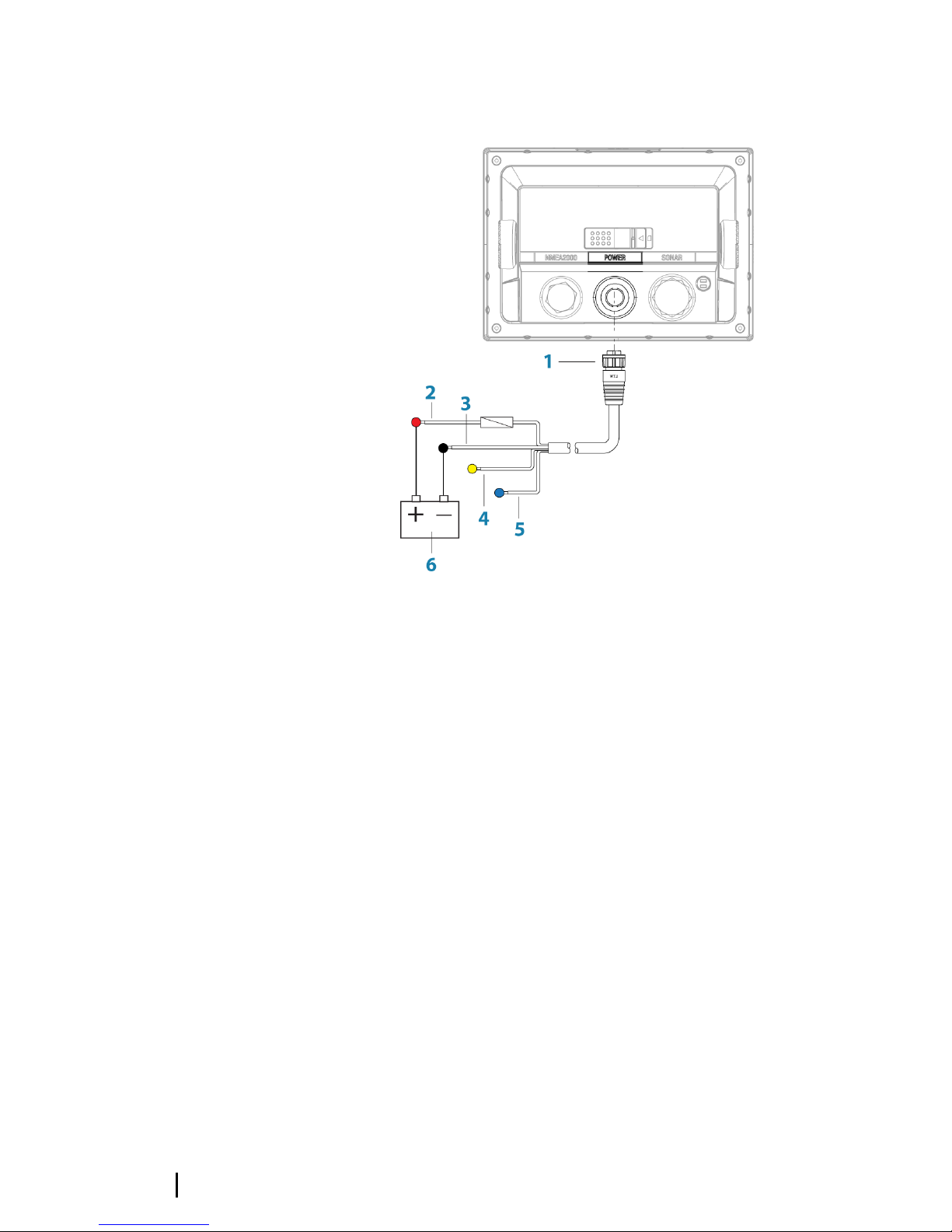
• Controlling power state of the unit (Yellow wire).
• Connecting to an external alarm (Blue wire).
1 Power cable connector
2 12 V positive wire (red) shown with fuse holder fitted
3 12 V negative wire (black)
4 Power control wire (yellow)
5 Alarm wire (blue)
6 Vessel’s 12 V DC supply
Connect Red to (+) DC using a 3 amp fuse.
Connect Black to (-) DC.
The unit can be powered on and off using the power button on the
front of the case.
Power control connection
The yellow Power Control wire on the GO7 power cable is an input
that will turn on the unit when power is applied.
16
Wiring | GO7 Installation Manual
Page 17

Power Control unconnected
Device will turn on and off when the power button on the front of
the unit is pressed. Leave the yellow Power Control wire
disconnected and tape or heat-shrink the end to prevent shorting.
Power Control to supply positive (auto on)
Device will turn on immediately when power is applied. Common
the yellow wire with the red wire after the fuse.
Ú
Note: The unit cannot be powered down by power button,
but can be put in to standby mode. (The screen backlight
also turns off.)
Power Control to ignition
Device will turn on once ignition is turned on to start engines.
Connect the yellow wire to the accessories output of the engine key
switch.
Ú
Note: Engine start batteries and house batteries should
have a common ground connection.
External alarm
Blue wire on power cable:
An external alarm can be connected to the GO7. The external alarm
can be a small piezo buzzer connected directly, or a horn siren
connected through a relay.
Alarms are configured globally in the system. That is, they can be
configured on any one networked multifunction device or Triton
instrument, and be seen, heard, and acknowledged from all devices.
Individual devices can also be configured to not sound their internal
buzzer, but still display the alarm information. For information about
configuring alarms, refer to the Alarms section in the Operator
Manual.
Wiring | GO7 Installation Manual
17
Page 18

For sirens that draw more than 1 Amp, use a relay.
Connecting control devices
The GO7 can be controlled with an OP40 keypad.
Ú
Note: An OP40 is required for Autopilot setup.
NMEA 2000 – connection to backbone
Device connection
The GO7 is equipped with an NMEA 2000 data port, which allows
the receiving and sharing of a multitude of data from various
sources.
18
Wiring | GO7 Installation Manual
Page 19

Essential network information
The standardized physical cables/connectors for NMEA 2000 are
Micro-C and Mini-C, directly derived from the automation industries
‘DeviceNET’ - ‘Micro-C’ being the more commonly used size.
• While most Navico products use Micro-C cabling and
connectors, some products still use proprietary SimNet
connectors, which are easily made compatible with adaptor
cables.
• A network consists of a linear backbone from which drop-
cables connect to NMEA 2000 compliant devices.
• A single drop cable has a maximum length of 6 m (20 ft). The
total length of all drop cables combined should not exceed 78
m (256 ft).
• A NMEA 2000 network, using Micro-C cabling, has a maximum
cable length of 100 m (328 ft), between any two points.
• A NMEA 2000 network needs to have a terminator at each end
of the backbone. A terminator can be one of the following:
• A terminator blank plug.
• A wind transducer (where the mast cable is one end of the
backbone).
Planning and installing a network backbone
The Micro-C backbone needs to run between the locations of all
products to be installed - typically in a bow to stern layout - and be
no further than 6 m from a device to be connected.
Choose from the following components to make up the backbone:
• Micro-C cables: 0.4 m (1.3 ft), 2 m (6,6 ft), 5 m (16.6 ft), and 9 m
(29.5 ft) cables.
• T-connector. Used to connect a drop cable to the backbone.
• Micro-C power cables. Connected to backbone using a T-
connector.
Ú
Note: When using a wind sensor, the mast cable should be
connected at one end of the backbone, as the sensor is
fitted with a termination resistor.
Ú
Note: Most NMEA 2000 devices can be connected directly
to a SimNet backbone and SimNet devices can be
connected to a NMEA 2000 network by using adapter
cables.
Wiring | GO7 Installation Manual
19
Page 20

Power the network
The network requires its own 12 V DC power supply protected by a
5 amp fuse or breaker. For vessels fitted with 24 V systems, use a DCDC converter to supply 12 V.
Connect power at any location in the backbone for smaller systems.
For larger systems introduce power at central point in the backbone
to “balance” the voltage drop of the network.
Ú
Note: If joining to an existing NMEA 2000 network that
already has its own power supply, do not make another
power connection elsewhere in the network, and ensure
the existing network is not powered by 24 V DC.
Ú
Note: Do not connect the NMEA 2000 power cable to the
same terminals as the engine start batteries, autopilot
computer, bow thruster or other high current devices.
The following drawing demonstrates a typical small network. The
backbone is made up of directly interconnected T-piece joiners and
an extension cable, which is terminated at each end.
1 NMEA 2000 connection
2 Drop-cable, should not exceed 6 m (20 ft)
3 Backbone
4 Power cable
20
Wiring | GO7 Installation Manual
Page 21

CZone connection to NMEA 2000
When interfacing to C-ZONE network it is recommended to use a
BEP Network interface bridge to join the two network backbones
together.
The CZONE / NMEA 2000 Network interface bridge isolates the
power of the two networks, but allows data to be freely shared
between both sides.
The Interface Bridge can also be used for expansion of the NMEA
2000 network, when the maximum node limit (node = any device
connected to network) for the network has been reached or the
maximum cable length of 150 m will be exceeded. Once an
Interface Bridge has been fitted, a further 40 nodes and additional
cable length can be added.
The Network Interface is available from your BEP dealer. For more
information please refer to the BEP web site www.bepmarine.com.
Transducer connection
Navico transducers fitted with a 7 pin blue connector can be
plugged directly into the corresponding blue socket labeled Sonar.
For connector location, refer to the embossed labeling on the unit
or the section "Overview" on page 10.
Ú
Note: The connector attached to the transducer cable is
keyed, and can only be inserted in one orientation. Once
inserted, turn locking collar to secure.
Ú
Note: The transducer is sold separately. Transducer
installation instructions are included with the transducer.
Wiring | GO7 Installation Manual
21
Page 22

Software Setup
The GO7 requires some initial configuration before use, in order to
get the most out of the product. The following sections focus on
settings that typically do not require change once configured. User
preference settings and operation are covered in the Operator
Manual. Selecting the Home button opens the Home page, which
has three distinct areas. The scrollable left column of icons is the
Tools panel and the icons access most settings that require
configuration.
First time startup
When the GO7 is started for the first time, or after a factory default,
the unit displays a setup wizard. Respond to the setup wizard
prompts to select some fundamental setup options.
Time and Date
Configure time settings to suit vessel location, along with time and
date formats.
Source selection
Data sources provide live data such as GPS position, heading, wind
speed, and temperature. The data may originate from modules
internal to the device (for example, internal GPS), or external
modules connected to the NMEA 2000 network. The internal virtual
devices typically include echo, MFD, Navigator, Pilot Controller, and
iGPS. When a device is connected to more than one source
providing the same data, the user has the flexibility to choose the
preferred source. Before commencing with source selection make
sure all external devices and the NMEA 2000 bus are connected and
are turned on.
Auto Select
The Auto Select option looks for all sources connected to the
device. If more than one source is available for each data type,
selection is made from an internal priority list. This option is suitable
for the majority of installations.
5
22
Software Setup | GO7 Installation Manual
Page 23

Manual source selection
Manual selection is generally only required where there is more
than one source for the same data, and the automatically selected
source is not the one desired.
Group source selection
Multifunction displays, autopilot controllers, and instruments have
the ability to:
• Use data sources (for example position, wind direction, and so
on) that all other products on the network use, or alternatively
use a data source independently from other units.
• Globally change all displays over to a different source from any
display. (This only includes products set to Group mode.)
Ú
Note: In order to enable group selection, the display must
be set to Simrad group.
Devices with the Group set to None can be set to use different
sources to those of the rest of the network devices.
Software Setup | GO7 Installation Manual
23
Page 24

Advanced source selection
This allows the most flexible and precise manual control over which
devices provide data. Some data sources, such as those for fuel
level, or engine RPM, can only be changed from the Advanced
menu. Occasionally Auto Select may not assign the desired source,
which may be corrected using the Advanced Source Selection. An
example of this is where twin installations with NMEA 2000
compliant engines are not programmed with unique instance
numbers. This means that the auto select feature cannot determine
which engine is fitted on the port and which is fitted on the
starboard side.
Ú
Note: The Advanced option is visible in multiple places -
the bottom of the Sources list, and under each source
category (for example, Compass). The latter shows a filtered
list that only relates to devices that output data relevant to
the category.
Autopilot setup
Verifying the autopilot connection
When an AC12N, AC42N, or SG05 is connected to the GO7 system,
the GO7 automatically detects the autopilot and an Autopilot menu
icon is included in the Settings menu.
If no Autopilot icon is available in the menu, establish the
connection by running the auto select process.
If the AC12N, AC42N, or SG05 is turned off independently of the
unit, the Autopilot menu icon remains available, but only a few of
the menu items are available.
Commissioning the autopilot
When the autopilot installation is completed, the commissioning
procedures must be performed. Failure in setting up the autopilot
correctly may prohibit the autopilot from functioning properly.
The setup of the autopilot computers can be done in full from the
GO7 or from a separate autopilot control head.
The following sections describe how you configure the autopilot
from the GO7 unit. If you connect the GO7 to an already
24
Software Setup | GO7 Installation Manual
Page 25

commissioned autopilot system, you only have to do an automatic
source selection as described above before the autopilot is ready to
be used.
Ú
Note: A dedicated physical STBY key is required for
commissioning. This can be on the Autopilot control head
or on an autopilot remote controller.
Dockside setup
Initiating the required dockside setup is done from within the
Commissioning dialog. Completed procedures are labelled with a
tick. When the autopilot computer is delivered from the factory AND
ANY TIME AFTER AN AUTOPILOT RESET HAS BEEN PERFORMED, you
will have to run a complete setup again.
All steps in all commissioning procedures are clearly described onscreen, and you are guided step by step through the process.
1. Press the STBY key to ensure that the autopilot is in standby
mode.
2. Select the Commissioning option and clear the displayed
dialog by pressing the STDBY key.
3. Select your boat type.
Software Setup | GO7 Installation Manual
25
Page 26

- The boat type setting is used by the system to select
appropriate preset steering parameters. It also affects
available autopilot features.
4. Perform the rudder calibration.
- Used if you have a rudder feedback unit installed. This
calibration is used to ensure that the physical rudder
movement corresponds to the rudder angle displayed on the
GO7 unit.
-
The Virtual Feedback option enables your autopilot to steer
without a conventional rudder feedback unit. This function is
designed for vessels up to 40 ft powered by outboard or stern
drives only.
- The Virtual Feedback option is only available when there is no
feedback unit connected at first time turn on, or at turn on
after an autopilot reset.
Ú
Note: Installing a feedback unit will enhance the
performance of the autopilot and provide an accurate
rudder angle indicator on the autopilot page. Unless
impractical or impossible, a rudder feedback unit should be
installed.
5. Set the drive voltage. Refer to the drive unit table in the AC12N/
AC42N Installation manual or to your drive unit documentation
for information.
6. Run the rudder test as described in the on-screen instructions.
Ú
Note: If the boat uses power assisted steering, it is
important that the engine or electric motor used to enable
the power assist steering is turned on prior to this test.
Warning: Stand CLEAR of the wheel and do not
attempt to take manual control of the wheel during
this test!
Ú
Note: When this test is started the autopilot computer
issues a series of PORT and STBD rudder commands and
automatically verifies correct rudder direction. It detects
minimum power to drive the rudder and reduces the
rudder speed if it exceeds the maximum preferred speed
(8°/sec.) for autopilot operation. The system also detects
whether the drive unit is a reversible motor or if a solenoid
valve is operated.
26
Software Setup | GO7 Installation Manual
Page 27

Rudder drive setup
The rudder drive setup controls how the autopilot computer
controls the steering system.
Drive voltage
Voltage specified for your drive unit. The Drive unit voltage setting
does not apply when the system operates solenoids on a
continuous running pump/steering gear. Hence, the output voltage
to the solenoids will be the same as the input voltage.
Refer to the drive unit table in the AC12N/AC42N Installation
manual or to your drive unit documentation for information.
Warning: Selection of improper voltage level for your
drive unit may damage both the drive unit and the
AC12N/AC42N even if the protection circuits are
activated.
Drive engage
Clutch
This is the default setting and it allows you to steer the boat with
the helm or wheel when in STBY mode (FU and NFU modes) as well
as in all auto steering modes.
Auto
This option is typically used to switch between two rudder speeds
on a continuous running pump, used when different rudder speeds
are required for automatic and Follow-up/Non-Follow-up steering.
Software Setup | GO7 Installation Manual
27
Page 28

Motor output
Shows the amount of power needed to achieve the correct rudder
speed. The reading is obtained from the Rudder test.
The automatically set value may be increased or decreased.
Rudder deadband
This parameter is used to prevent the rudder from hunting. The
reading is obtained from the Rudder test which optimizes the
deadband to the speed of the boat and the pressure on the rudder.
If the auto-setting does not perform properly due to high inertia
from the wheel or a loose steering gear, it can be adjusted manually.
Find the lowest possible value that will prevent the rudder from
continuous hunting. A wide deadband causes inaccurate steering.
Ú
Note: The rudder deadband setting is not available when
the autopilot is configured for Virtual Rudder Feedback.
Seatrials
A seatrial can only be performed if the dockside settings are
completed and confirmed. The seatrial must always be performed in
open waters at a safe distance from other traffic.
Ú
Note: You can switch the autopilot to standby mode and
take manual control of the boat at any time during the
seatrial by pressing the STBY key on the OP40.
The following seatrial calibration should be done:
• Compass calibration; used to automatically compensate for on-
board magnetic interference
• Compass offset adjustment, used to compensate for a fixed
offset in the final heading readout
• Wind vane offset is to compensate for a wind vane that is not
mounted facing in exactly the same direction as the bow of the
vessel (dead ahead)
• Boat speed calibration
• Transition HI/LO speed setting (the speed at which you want to
change the set of steering parameters)
• Automatic tuning of the steering parameters
• Setting the seastate filter
• Sailboat Setup menu items
28
Software Setup | GO7 Installation Manual
Page 29

Compass calibration
Before the compass calibration is started, make sure that there is
enough open water around the vessel to make a full turn. The
calibration should be done in calm sea conditions and with minimal
wind to obtain good results. Follow the on-screen instruction, and
use about 60-90 seconds to make a full circle. During the calibration,
the compass measures the magnitude and direction of the local
magnetic field.
• If the local magnetic field is stronger than the earth’s magnetic
field (the local field is reading more than 100 %), the compass
calibration will fail.
• If the local field is reading more than 30 %, you should look for
any interfering magnetic objects and remove them, or you
should move the compass to a different location. The (local)
field angle guides you to the local interfering magnetic object.
Ú
Note: Calibration must be made on the compass that is
active for the autopilot. If the compass is not possible to
initiate calibration from the device list on the GO7, refer to
the compass’ own instructions regarding calibration.
Ú
Note: In certain areas and at high latitudes the local
magnetic interference becomes more significant and
heading errors exceeding ±3° may have to be accepted.
Compass mounting offset
After compass calibration, the difference (if any) between the
compass lubber line and the boat’s center line should be
compensated for.
1. Find the bearing from the boat position to a visible object. Use a
chart or a chart plotter.
2. Steer the boat so that the center line of the boat is aligned with
the bearing line pointing towards the object.
3. Change the offset parameter so that the bearing to the object
and the compass readout becomes equal.
Ú
Note: Make sure that both the compass heading and the
bearing to the object have the same unit (°M or °T).
Software Setup | GO7 Installation Manual
29
Page 30

Setting the Transition speed (HI/LO)
This is the speed at which the system automatically changes from
LO to HI steering parameters.
On power boats it is recommended that you set a value that
represents the speed where the hull begins to plane, or the speed
where you change from slow to cruising speed.
On sailboats the transition speed should be set to around 3-4 knots
to give the best response in a tack.
A deadband of 2 knots is incorporated to prevent oscillation of
HI/LO settings when vessel is travelling at the transition speed.
1 HI response
2 LO response
3 Transition to HI parameters with decreasing speed: 8kn
4 Transition speed set to 9kn
5 Transition to LO parameters with increasing speed: 10kn
Active response parameter set is shown in the autopilot popup and
the following abbreviations are used:
HI-A High response parameters set automatically
LO-A Low response parameters set automatically
HI-M High response parameters set manually
LO-M Low response parameter set manually
30
Software Setup | GO7 Installation Manual
Page 31

Autotuning
The autotune feature runs the boat through several tests and then
automatically sets the most important steering parameters.
Autotune is not required for the autopilot to function, as it is preset
with steering parameters that should steer most boats in the 30-50
foot range. All parameters that are set during autotuning can be
manually adjusted.
Seastate filter
The Seastate filter is used to reduce rudder activity and autopilot
sensitivity in rough weather.
OFF
Seastate filter is disabled. This is default.
AUTO
Reduces rudder activity and autopilot sensitivity in rough weather
by an adaptive process. The AUTO setting is recommended if you
want to use the seastate filter.
MANUAL
Linked to the steering response control settings described
previously. It may be used to manually find the optimum
combination of course keeping and low rudder activity in rough but
steady sea conditions.
Software Setup | GO7 Installation Manual
31
Page 32

Setting sailing parameters
Ú
Note: Sailing parameter settings are only available if the
boat type is set to Sail in the Autopilot Commissioning
dialog.
Tack time
When performing a tack in WIND mode, the rate of turn (tack time)
can be adjusted. This gives single-handed sailors time to handle the
boat and the sails during a tack. A turn performed without shifting
wind side, is also made at a controlled turn rate.
Range: 2-50
Change per step: 1
Default: 12
Units: Seconds
Tack angle
This value is used to preset the course change used when tacking in
AUTO mode. When you select the left or right arrow key on the
Autopilot pop-up, the course changes as much as this value.
Range: 50-150
Change per step: 1
Default: 100
Units: Degrees
32
Software Setup | GO7 Installation Manual
Page 33

Wind function
With wind function set to Auto, the autopilot automatically selects
between apparent and true wind steering. Auto is default and
recommended for cruising.
When the boat is running or on a broad reach, there is a greater
chance it will surf on the waves. This may lead to significant
changes in boat speed, and thereby changes in apparent wind
angle. True wind steering is therefore used to prevent undesired
corrections by the autopilot when heading downwind (or close to),
while steering to apparent wind is used when beating or reaching.
Apparent wind steering is preferred when you want to maintain
maximum boat speed without continuous trimming of the sails.
VMG optimizing
You can optimize the VMG to wind. When selected, the function will
be active for 5–10 minutes after a new wind angle has been set and
only when beating.
Layline steering
Layline steering is useful when navigating. Cross Track Error (XTE)
from the navigator keeps the boat on the track line. If the XTE from
the navigator exceeds 0.15 nm, the autopilot calculates the layline
and track towards the waypoint.
Manually adjusting steering parameters
The autotune function in the autopilot is so refined that the majority
of boats need no further adjustments of the steering parameters.
On some boats however, or in particular sea conditions, fine tuning
of the steering parameters may improve the performance of the
autopilot.
Transition speed
Refer to "Setting the Transition speed (HI/LO)" on page 30.
Rudder
This parameter determines the ratio between commanded rudder
and the heading error. The higher rudder value the more rudder is
applied. If the value is too small it will take a long time to
compensate for a heading error, and the autopilot will fail to keep a
steady course. If the value is set too high the overshoot will increase
and the steering will be unstable.
Software Setup | GO7 Installation Manual
33
Page 34

Counter rudder
Counter rudder is the amount of rudder used to try to prevent the
boat from yawing around the set course. Higher counter rudder
settings result in more rudder being applied.
The best way of checking the value of the Counter rudder setting is
when making turns.
The following figures illustrate the effects of various Counter Rudder
settings:
1 Counter rudder too low; overshoot response.
2 Counter rudder too high; sluggish and creeping response.
3 Correct setting of counter rudder; ideal response.
Auto trim
This parameter defines how fast the autopilot shall correspond after
having registered a heading error.
The standard value is 40 seconds which should work well on most
boats. Rule of thumb: Set to same value (seconds) as the boat’s
length in feet. On boats operating on VRF, the value should be set
to 20 seconds.
Rate limit
Sets the maximum allowed rate of turn.
The value should be kept at 6.0°/second unless there is a need for
more rapid response in turns.
Minimum rudder
This parameter filters small rudder commands to prevent high
rudder activity.
Some boats may have a tendency to not respond to small rudder
commands around the “course keeping” position because of a small
34
Software Setup | GO7 Installation Manual
Page 35

rudder, a rudder deadband, whirls/disturbance of the water-stream
passing the rudder, or it is a single nozzle water jet boat.
By increasing the Minimum rudder parameter you may improve the
course keeping performance on some boats. However, this will
increase the rudder activity.
Minimum wind angle to port and starboard
These parameters should be set identical to the minimum apparent
wind angle that will keep the sails from stalling and maintain boat
speed. The parameters vary from boat to boat.
The settings are used for the tack-prevent function. They also apply
when the autopilot is operating in WindNAV mode.
You can select different minimum wind angles for port and
starboard. The difference between port and starboard is taken into
account when calculating the Distance To Turn (DTT).
Navigation change limit
This parameter defines the maximum course change that the
autopilot is allowed to make when the GO7 is following a route
(NAV steering).
If the required course change to the next waypoint in a route is
more than the set limit, you are prompted and must acknowledge
the course change before the autopilot will turn the vessel.
Fuel setup
The fuel utility monitors a vessel's fuel consumption. This
information is totaled to indicate trip and seasonal fuel usage, and is
used to calculate fuel economy for display on instrument pages and
the data bar.
To use the utility, a Navico Fuel Flow sensor, or a NMEA 2000 engine
adaptor cable/gateway with Navico Fuel Data Storage device must
be fitted to the vessel. Neither the Navico Fuel Flow sensor, nor the
Suzuki engine interface require the use of a separate Fuel Storage
device. Refer to the engine manufacturer or dealer for information
on whether or not your engine provides a data output, and what
adaptor is available to connect to NMEA 2000.
Once the physical connection is made, ensure source selection is
completed. Multiple engine installations using Fuel Flow sensors, or
Fuel Data Storage devices, require setup of related engine location
Software Setup | GO7 Installation Manual
35
Page 36

in the Device list. For general source selection information, refer to
"Source selection" on page 22.
Ú
Note: Multiple engines using a single gateway do not work
with the Navico Fuel Storage device.
Vessel setup
The Vessel setup dialog must be used to select the number of
engines, the number of tanks and vessel’s total fuel capacity across
all tanks.
Fuel flow configuration
After the number of engines is set, it is required to set which fuel
flow sensor is connected to which engine. Under Device list on the
Network page, view the Device Configuration dialog for each
sensor, and set the Location to match the engine the device is
connected to.
Unconfigure - defaults the device which clears all user settings.
Reset Fuel Flow - restores only the Fuel K-Value setting, if set in
Calibrate. Only Navico devices can be reset.
36
Software Setup | GO7 Installation Manual
Page 37

Calibrate
Calibration may be required to accurately match measured flow
with actual fuel flow. Access calibration from the Refuel dialog.
Calibration is only possible on Navico’s Fuel Flow sensor.
1. Start with a full tank and run the engine as it would normally be
operated.
2. After at least several liters (a few gallons) have been used, the
tank should be fully refilled, and the Set to full option selected.
3. Select the Calibrate option.
4. Set the actual amount used based on amount of fuel added
to the tank.
5. Select OK to save settings. The Fuel K-Value should now show
a new value.
Ú
Note: To calibrate multiple engines repeat the steps above,
one engine at a time. Alternatively, run all engines
simultaneously, and divide the Actual amount used by the
number of engines. This assumes reasonably even fuel
consumption on all engines.
Ú
Note: The Calibrate option is only available when Set to
full is selected, and a Fuel Flow is connected and set up as
a source.
Ú
Note: A maximum of 8 engines is supported using Fuel
Flow sensors.
Software Setup | GO7 Installation Manual
37
Page 38

Fuel Level
With the use of a Navico Fluid Level device connected to a suitable
tank level sensor, it is possible to measure the amount of fuel
remaining in any equipped tank. The number of tanks must be set
in Vessel Setup dialog, initiated from the Fuel setting options page,
to allow discrete tank assignment of the Fluid Level devices. Select
Device list on the Network page, and view the Device
Configuration dialog for each sensor, and set the Tank location,
Fluid type, and Tank size.
For setting up the Instrument bar or a gauge on the Instrument
page with Fluid Level device data, refer to the Operator Manual.
Ú
Note: A maximum of 5 tanks is supported using Fluid Level
devices.
Ú
Note: Tank data that is output by a compatible engine
gateway can also be displayed, however tank configuration
for such a data source is not possible from the GO7.
CZone setup
In order to communicate with the CZone modules connected to
the network, the GO7 must be assigned a unique CZone Display
Dipswitch setting.
The functionality of the CZone system is determined by the CZone
Config File (.zcf ), which is stored on all CZone modules and the
GO7. The file is created using the CZone Configuration Tool, a
38
Software Setup | GO7 Installation Manual
Page 39

specialized PC application available from BEP Marine Ltd, and
associated CZone distributors.
The GO7 system provides a means to load the Config file, as well as
apply updates to module firmware, removing the need to take a
laptop computer aboard the vessel.
Enabling CZone functionality
If the CZone device(s) are not automatically detected, it is possible
to manually enable CZone.
Assigning the dipswitch setting
Every product capable of controlling and viewing CZone devices
must be assigned a virtual dipswitch setting. This setting is unique
for each device. Typically it is set after the configuration file already
exists on the CZone system, but it may also be set in advance. To do
so, access the CZone menu on the Settings page.
When the configuration is already available on the network, it will
immediately commence uploading to the GO7 once the dipswitch
is set. Allow this to complete, without interruption.
Setting CZone to display at startup
With this option selected, the CZone control page is shown first,
every time the GO7 is powered up.
Software Setup | GO7 Installation Manual
39
Page 40

CZone backlight control
Enabling this causes the GO7 to synchronize its backlight setting
with that of any CZone Display Interfaces set up to share backlight
settings.
Ú
Note: CZone Config also needs to have the GO7 set as a
controller.
Import and backup a configuration file
The files page may be used to import CZone configuration files, or
export a copy to a memory card in the card reader. Importing
overwrites the existing file on the GO7 and all connected CZone
devices.
For further information, see "Backing up and Importing user data" on page
43.
Upgrading module firmware
The Files page also allows the loading of NMEA 2000 devices
firmware upgrades. For example, CZone firmware updates. For more
information, refer to "NMEA 2000 device upgrades" on page 45.
Wifi setup
The GO7 includes built-in wireless functionality that lets you use a
wireless device to remotely view (phone and tablet) and control the
system (tablet only). The system is controlled from the wireless
device by Apps downloaded from their relevant Application store.
Various 3rd party applications can also use the data stream.
Connecting the tablet
1. Navigate to the wifi network connection page on the tablet, and
find the GO7, or GoFree Wifi xxxx network. If more than one is in
range, review the Wireless Devices page on the GO7 to confirm
which wireless device is connected to the unit.
2. Select a device on this page to show its network key.
3. Enter the eight character (or longer) Network Key in to the tablet
to connect to the network.
4. Open the GoFree application - the GO7 should be automatically
detected. The name displayed will be either the default, or that
40
Software Setup | GO7 Installation Manual
Page 41

assigned in the Device Name setting. If the GO7 does not
appear, follow the on screen instructions to manually find the
device.
5. Select the graphic icon of the GO7. The GO7 displays a prompt
similar to the following:
6. Select Yes for one-time connection, or Always if device is to be
remembered for regular connection. This setting can be
changed later if required.
Ú
Note: The internal wireless module only supports GoFree
connection to itself. Other units connected on the network
are not visible.
Remote controllers
When a wireless device is connected, it should appear in the
Remote controllers list. Selecting Always allow means the device
can automatically connect without needing a password each time.
This menu also allows disconnection of devices that no longer
require access.
Wireless device
This page shows the internal wireless module and its IP and channel
number.
Selecting the device provides additional detail. The Network Name
and the Network Key can be edited for security, and Channel can be
changed if the connection to the unit is compromised due to
interference by another RF device transmitting in the same
frequency band. Restore defaults returns the unit to factory settings.
Software Setup | GO7 Installation Manual
41
Page 42

Advanced
Tools are available within the GO7 software to assist in fault-finding
and setting up the wireless network.
Iperf
Iperf is a commonly used network performance tool. It is provided
for testing wireless network performance around the vessel so weak
spots or problem areas can be identified. The application must be
installed on and run from a tablet device. The GO7 must be running
Iperf server before initiating the test from the tablet. On exiting the
page, Iperf automatically stops running.
DHCP Probe
The wireless module contains a DHCP server that allocates IP
addresses for all the MFDs, and Echosounder in a network. If
integrating with other devices, such as a 3G modem or satellite
phone, other devices in the network may also be acting as DHCP
servers. To make it easy to find all DHCP servers on a network,
dhcp_probe may be run from the GO7. Only one DHCP device may
be operational on the same network at a time. If a second device is
found, turn off its DHCP feature if possible. Refer to the device’s own
instructions for further assistance.
Ú
Note: Iperf and DHCP Probe are tools provided for
diagnostic purposes by users familiar with network
terminology and configuration. Navico is not the original
42
Software Setup | GO7 Installation Manual
Page 43

developer of these tools, and cannot provide support
related to their use.
Internal Wireless
Select this option to enable or disable the internal wireless module.
Disabling wireless when not in use reduces the unit’s power
consumption.
Software updates and data backup
From time to time we release software updates to our existing
products. Updates are created for a variety of reasons; to add or
improve features, to add support for new external devices, or to fix
software bugs.
Updates can be found on the website: simrad-yachting.com
The GO7 may be used to apply software updates to itself, and to
supported NMEA 2000 network devices, with files read off a
memory cord inserted in the card reader.
Before initiating an update to the GO7 itself, be sure to back up any
potentially valuable user data.
Backing up and Importing user data
There are two files that can be backed up that relate to user
changes made to the system:
• Waypoints, Routes, and Tracks database.
• Settings database (includes preferences such as unit settings,
custom pages, and CZone configuration files).
Insert a memory card into the unit's card reader as a storage
location for backup data.
Waypoints, Routes, and Tracks database backup
You can export all Waypoints, Routes, and Tracks, or export only
those contained within a specific region.
If Export Region is selected, the chart page will be displayed,
centered on vessel location. Using the touch screen, adjust the red
boundary box to outline the area to be exported. The export option
offers different file formats to save as:
Software Setup | GO7 Installation Manual
43
Page 44

• User data file version 5: Use with current units (NSO evo2,
NSS evo2, NSS, NSO, NSE, Zeus, Zeus Touch, HDS Gen2, HDS
Gen2 Touch, HDS Gen3). Offers most detail.
• User data file version 4: Use with current units (NSO evo2,
NSS evo2, NSS, NSO, NSE, Zeus, Zeus Touch, HDS Gen2, HDS
Gen2 Touch, HDS Gen3).
• User data file version 3 (with depth): Use with legacy GPS
chartplotters.
• User data file version 2 (no depth): Use with legacy GPS
chartplotters.
• GPX (GPS Exchange, no depth): Use with some other
manufacturers’ GPS products, and PC applications.
After you select the file type, select Export and destination memory
card. The receiving GPS/PC will typically need to be set to allow
import of Waypoints.
Settings database export
Select Setting database to export the Settings database, or export
CZone configuration (CZone installation dependent). Choose the
desired option and select the memory card destination.
Importing a database
Later, if the GO7 has been restored to factory defaults or user data is
accidentally deleted, return to the files page, select the backed up
file, and then Import. View file details for creation date.
Software upgrades
The update file must be loaded to the root directory of the memory
card.
The update may be initiated at boot up: insert the memory card into
the card reader before turning the unit on, boot the unit, and follow
the on-screen instructions.
Alternatively, in the Files menu, locate the update file on the
memory card inserted in the card reader and select Upgrade,
followed by This Display. Accept the prompt to reboot the unit,
and wait a few moments as the unit restarts. Do not remove the
memory card or repower the GO7 until the process is completed
(this typically takes no more than a couple of minutes).
44
Software Setup | GO7 Installation Manual
Page 45

Software upgrade of remote device
It is possible to run an update remotely from one unit and apply it
to another, provided they are on the NMEA network. This is only
possible for units without a card slot.
Remote updating is similar to updating a local unit; select the file on
the memory card and select the Upgrade option, followed by
Remote Upgrade. Follow the onscreen options.
NMEA 2000 device upgrades
The update file must be loaded to the root directory of a memory
card. inserted in the card reader.
To update NMEA 2000 devices select the Upgrade option
presented when the file is highlighted. A list should appear
displaying any compatible devices the update file applies to. In
most cases this will be a single device. Select the device and initiate
the upgrade. Do not interrupt the upgrade process.
Ú
Note: If no device is shown, check that the device to be
updated has power, and run any outstanding updates for
the unit first.
NMEA 2000 setup
Receive waypoint
Select this option to allow another device capable of creating and
exporting waypoints via NMEA 2000 to transfer directly to the GO7.
Software Setup | GO7 Installation Manual
45
Page 46

Send waypoint
Select this option to allow another device to send waypoints via
NMEA 2000.
46
Software Setup | GO7 Installation Manual
Page 47

Accessories
Ú
Note: The most up-to-date accessories list is available at:
simrad-yachting.com
Part number Description
000-12366-001 GO7 Flush Mount Kit
000-12368-001 GO7 Flush Mount Sun Cover
000-12367-001 GO7 Bracket and Panel Mount Sun Cover
000-12371-001 GO7 Panel Mount Kit
000-12372-001 GO7 U Bracket
000-00128-001 Power Cable
6
Accessories | GO7 Installation Manual
47
Page 48

Supported data
NMEA 2000 compliant PGN List
NMEA 2000 PGN (receive)
59392 ISO Acknowledgement
59904 ISO Request
60928 ISO Address Claim
61184 Parameter Request/Command
65285 Temperature with Instance
65289 Trim Tab Insect Configuration
65291 Backlight Control
65292 Clear Fluid Level Warnings
65293 LGC-2000 Configuration
65323 Data User Group Request
65325 Reprogram Status
65341 Autopilot Mode
65480 Autopilot Mode
126208 ISO Command Group Function
126992 System Time
126996 Product Info
127237 Heading/Track Control
127245 Rudder
127250 Vessel Heading
127251 Rate of Turn
127257 Attitude
127258 Magnetic Variation
127488 Engine Parameters, Rapid Update
127489 Engine Parameters, Dynamic
127493 Transmission Parameters, Dynamic
7
48
Supported data | GO7 Installation Manual
Page 49

127503 AC input status
127504 AC Output Status
127505 Fluid Level
127506 DC Detailed Status
127507 Charger Status
127508 Battery Status
127509 Inverter Status
128259 Speed, Water referenced
128267 Water Depth
128275 Distance Log
129025 Position, Rapid Update
129026 COG & SOG, Rapid Update
129029 GNSS Position Data
129033 Time & Date
129038 AIS Class A Position Report
129039 AIS Class B Position Report
129040 AIS Class B Extended Position Report
129041 AIS aids to Navigation
129283 Cross Track Error
129284 Navigation Data
129539 GNSS DOPs
129540 AIS Class B Extended Position Report
129794 AIS aids to Navigation
129801 Cross Track Error
129283 Cross Track Error
129284 Navigation Data
129539 GNSS DOPs
129540 GNSS Sats in View
129794 AIS Class A Static and Voyage Related Data
129801 AIS Addressed Safety Related Message
129802 AIS Safety Related Broadcast Message
129808 DSC Call Information
Supported data | GO7 Installation Manual
49
Page 50

129809 AIS Class B “CS” Static Data Report, Part A
129810 AIS Class B “CS” Static Data Report, Part B
130074 Route and WP Service - WP List - WP Name & Position
130306 Wind Data
130310 Environmental Parameters
130311 Environmental Parameters
130312 Temperature
130313 Humidity
130314 Actual Pressure
130576 Small Craft Status
130577 Direction Data
130840 Data User Group Configuration
130842 SimNet DSC Message
130845 Parameter Handle
130850 Event Command
130851 Event Reply
130817 Product Info
130820 Reprogram Status
130831 Suzuki Engine and Storage Device Config
130832 Fuel Used - High Resolution
130834 Engine and Tank Configuration
130835 Set Engine And Tank Configuration
130838 Fluid Level Warn
130839 Pressure Insect Configuration
130840 Data User Group Config
130842 AIS and VHF Message Transport
130843 Sonar Status – Frequency and DSP Voltage
130845 Weather and Fish Prediction and Barometric Pressure
History
130850 Evinrude Engine Warnings
130851 Parameter (RC42 Compass and IS12 Wind Calibration
and Configuration)
50
Supported data | GO7 Installation Manual
Page 51

NMEA 2000 PGN (transmit)
61184 Parameter Request/Command
65287 Configure Temperature Insects
65289 Trim Tab Insect Calibration
65290 Paddle Wheel Speed Configuration
65291 Backlight Control
65292 Clear Fluid Level Warnings
65293 LGC-2000 Configuration
65323 Data User Group Request
126208 ISO Command Group Function
126992 System Time
126996 Product Info
127237 Heading/Track Control
127250 Vessel Heading
127258 Magnetic Variation
128259 Speed, Water referenced
128267 Water Depth
128275 Distance Log
129025 Position, Rapid Update
129026 COG & SOG, Rapid Update
129029 GNSS Position Data
129283 Cross Track Error
129284 Navigation Data
129285 Route/Waypoint Data
129539 GNSS DOPs
129540 GNSS Sats in View
130074 Route and WP Service - WP List - WP Name & Position
130306 Wind Data
130310 Environmental Parameters
130311 Environmental Parameters
Supported data | GO7 Installation Manual
51
Page 52

130312 Temperature
130577 Direction Data
130840 Data User Group Configuration
130845 Parameter Handle
130850 Event Command
130818 Reprogram Data
130819 Request Reprogram
130828 Set Serial Number
130831 Suzuki Engine and Storage Device Config
130835 Set Engine And Tank Configuration
130836 Fluid Level Insect Configuration
130837 Fuel Flow Turbine Configuration
130839 Pressure Insect Configuration
130845 Weather and Fish Prediction and Barometric Pressure
History
130850 Evinrude Engine Warnings
130851 Parameter (RC42 Compass and IS12 Wind Calibration
and Configuration)
52
Supported data | GO7 Installation Manual
Page 53

Specifications
Ú
Note: The most up-to-date specifications list is available at:
simrad-yachting.com
Mechanical/Environmental
Casing PC/ABS
Operating temp -15°C to +55°C (+5°F to +131°F)
Water ingress IPX6 and 7
Weight (excluding mounting
hardware)
1.310 kg
Screen brightness 1200nits
Screen resolution 480 x 800 (H x W)
Viewing angle in degrees
(typical value at contrast ratio =
10)
L/R: 70, top: 50, bottom: 60
Dimensions (overall) See dimensioned drawings
Electrical
Operating voltage 10 - 17 V DC
Current draw at 13.6V (sonar off,
max B/L)
1 A
Low power standby mode yes
Protection reverse polarity and temporary
over-voltage to 36V
Alarm output current 1 A max
Processor iMX61 single core
Conformity CE, C-Tick
Interfaces
NMEA 2000 (compliant) 1 port (Micro-C male)
Sonar 1 port (7 pin blue connector)
microSD card reader 1x microSD
8
Specifications | GO7 Installation Manual
53
Page 54

Dimensional drawings
9
54
Dimensional drawings | GO7 Installation Manual
Page 55

Page 56

*988-10841-001*
0980
 Loading...