

Page 1

INSTRUCTION MANUAL
SIMRAD GC80/85
EXPANDED
Gyro Compass
20221529C English
Page 2
Simrad GC80/GC85 Expanded Gyro Compass
ii 20221529 / C
Document revisions
Rev Date Written by Checked by Approved by
A 08.01.04
B 17.02.05
C 05.12.05
Document history
Rev. A First issue.
Rev. B Updated for new software release (Master compass: V.1.03, Control
unit: V.1.04).
Rev. C New procedure for how to adjust true heading, updated dimensions for
remote panel, other minor updates to text throughout the manual.
Page 3

INSTRUCTION MANUAL
20221529 / C iii
About this manual
This manual is intended as a reference guide for installing, operating and maintaining
Simrad GC80 and GC85 Expanded Gyro compasses.
The manual assumes that the operator is a qualified ship officer, or is under supervision
of a qualified person.
In this manual, references to buttons on the operator panels are written in boldface, but
in a different text style (e.g. SET button, DISP button, GYRO button).
Important text that requires special attention from the reader is emphasized as follows:
Note! Used to draw the reader’s attention to a comment or some
important information.
Caution Used for warning the reader that a risk of damage to the
equipment exists if care is not exercised.
WARNING Used when it is necessary to warn personnel
that a risk of injury or death exists if care is
not exercised.
Page 4

Simrad GC80/GC85 Expanded Gyro Compass
iv 20221529 / C
This manual is divided in the following sections:
1. System overview
An overview of the GC80/GC85 Expanded gyro system and it’s components.
2. User interface
Overview of GC80 Expanded Control unit and the user interface.
3. Operation
Main operating procedures for using the GC80/GC85 Expanded Gyro compass.
4. Maintenance
Simple maintenance procedures that should be performed by the system operator,
together with a complete procedure for how to replace the sensitive element and fuses.
5. Installation
Mechanical installation, cable connection, and software configuration for the
GC80/GC85 Expanded gyro system.
6. Advanced settings
A description of parameters that can be entered or changed in the Extension menu.
7. Technical specifications
Specifications for the system and for all separate units in the GC80/GC85 Expanded gyro
system.
8. Drawings
Outline drawings and wiring diagrams for the GC80/GC85 Expanded gyro system.
9. Spare part list
List of all standard and optional units that are used in the GC80 and GC85 Expanded
gyro systems.
10. Terminal layout
List of all terminal pins and terminal labelling with details on GTERM board in the
GC80 Control unit.
11. Dip switch settings
Drawings and references of jumpers and dip switches for the different printed circuits
boards in the Control unit.
12. Alarm messages and corrective actions
A description of how system errors are indicated, and corrective actions that can be
performed by the operator.
Page 5

INSTRUCTION MANUAL
20221529 / C v
Contents
1 SYSTEM OVERVIEW...........................................................1
1.1 Introduction.......................................................................2
1.2 Precaution in use................................................................ 3
1.3 System components............................................................4
1.4 Bearing repeaters ...............................................................4
2 USER INTERFACE ..............................................................5
2.1 GC80 Expanded Control unit ................................................6
3 OPERATION.......................................................................9
3.1 System Start-up and Shut-down......................................... 10
Start-Up .................................................................... 10
Turning the Gyro compass OFF...................................... 11
3.2 Selecting active compass ................................................... 12
3.3 Adjusting dimming level .................................................... 12
3.4 Displaying present settings ................................................ 13
3.5 Confirming present settings ............................................... 15
True bearing............................................................... 15
Latitude ..................................................................... 15
Speed........................................................................ 16
3.6 Pendulum function ............................................................ 18
3.7 Alarm messages ............................................................... 19
Acknowledging an alarm .............................................. 20
4 MAINTENANCE ................................................................ 21
4.1 General........................................................................... 22
4.2 Precautions...................................................................... 22
4.3 Cleaning the operator panels and the cabinet surface ............ 22
4.4 Checking the connectors.................................................... 22
4.5 Checking mechanical installation......................................... 22
4.6 Preventive maintenance intervals........................................ 23
4.7 Replacing the Sensitive element ......................................... 23
Mechanical installation ................................................. 23
Verifying the element’s tilt angle ................................... 27
Parameter updates ...................................................... 28
Page 6

Simrad GC80/GC85 Expanded Gyro Compass
vi 20221529 / C
Balancing the Horizontal ring ........................................ 29
4.8 Replacing the Fuses .......................................................... 30
Master Compass.......................................................... 30
Expanded Control unit.................................................. 31
5 INSTALLATION................................................................33
5.1 Unpacking and handling .................................................... 34
5.2 Mechanical installation ...................................................... 34
Control unit ................................................................ 35
Master compass .......................................................... 37
5.3 Cabling ........................................................................... 38
Power supply .............................................................. 39
5.4 Grounding the units .......................................................... 40
5.5 Dip-switch settings ........................................................... 40
Configuring the Control unit.......................................... 41
External heading sensor ............................................... 42
Pendulum function....................................................... 43
5.6 Installing the Sensitive element .......................................... 44
Verifying the element’s tilt angle ................................... 46
5.7 System start-up and software configuration ......................... 48
System Start-up ......................................................... 48
Configuring the gyro system ......................................... 49
Setting the Latitude input system .................................. 51
Setting the Speed input system..................................... 52
5.8 Balancing the Horizontal ring.............................................. 53
Adjusting True heading ................................................ 53
6 ADVANCED SETTINGS .....................................................55
6.1 General........................................................................... 56
6.2 Using the Extension menu ................................................. 56
6.3 The Extension menu overview ............................................ 57
7 TECHNICAL SPECIFICATION ...........................................63
7.1 Accuracy ......................................................................... 64
7.2 General specification ......................................................... 64
7.3 Input specification ............................................................ 65
7.4 Output specification .......................................................... 66
7.5 Physical Dimensions.......................................................... 67
Page 7

INSTRUCTION MANUAL
20221529 / C vii
GC80/GC85 Master Compass ........................................67
GC80 Expanded Control Unit......................................... 67
7.6 Power ............................................................................. 68
GC80/GC85 Master Compass ........................................68
GC80 Expanded Control Unit......................................... 68
7.7 Environmental Specification ............................................... 68
GC80/GC85 Master Compass ........................................68
GC80 Expanded Control unit ......................................... 68
8 DRAWINGS .....................................................................69
8.1 Drawings included ............................................................ 70
9 SPARE PART LIST............................................................77
9.1 GC80 Expanded Gyro system ............................................. 78
9.2 GC85 Expanded Gyro system ............................................. 78
9.3 Optional equipment, GC80/85 Expanded system ................... 79
10 TERMINAL LAYOUT .........................................................81
10.1 GTERM board................................................................... 82
TB1 ........................................................................... 82
TB2 ........................................................................... 84
11 DIP SWITCH SETTINGS ...................................................87
11.1 Expanded control unit .......................................................88
GPOWER board ........................................................... 89
GTERM board.............................................................. 90
SCC board.................................................................. 91
SIFC board................................................................. 95
12 ALARM MESSAGES AND CORRECTIVE ACTIONS.............101
12.1 The alarm system........................................................... 102
12.2 Acknowledging an alarm.................................................. 103
12.3 Fault finding .................................................................. 104
Main power failure..................................................... 104
Internal power failure in Control unit............................ 105
Inverter failure ......................................................... 105
Zero cross failure ...................................................... 105
System communication failure .................................... 106
GPS communication or data failure .............................. 106
Page 8

Simrad GC80/GC85 Expanded Gyro Compass
viii 20221529 / C
Internal communication failure .................................... 107
External bearing sensor failure .................................... 107
LOG (serial) communication or data failure ................... 107
Repeater failure ........................................................ 108
Failure when powering ON the gyro compass ................ 108
12.4 Complete alarm code list ................................................. 109
Page 9

SYSTEM OVERVIEW
20221529 / C 1
1 SYSTEM OVERVIEW
This section provides an overview of GC80 and GC85
Expanded Gyro compasses and their components.
Page 10

Simrad GC80/GC85 Expanded Gyro Compass
2 20221529 / C
1.1 Introduction
GC80 and GC85 Expanded Gyro compasses have been
designated for any size of vessels to enhance the navigation
capabilities and reliability. The gyro compasses eliminate the
inconvenience and limitations of magnetic compasses, and
provide a variety of electrical outputs to supply accurate and
consistent heading information to other navigational equipment.
- A GC80 Expanded gyro is designed for vessels with speed
up to 30 knots. The system complies with IMO A.424 (11)
and Wheel Mark Specifications.
- A GC85 Expanded gyro system is suitable for high speed
vessels with speed up to 70 knots. It complies with IMO
A.821 (19) HSC.
GC80 and GC85 Expanded gyro systems have different
sensitive elements, but use the same GC80 Expanded Control
unit. The systems are identified with divergent dip switch
settings in Master compass and in the Control unit.
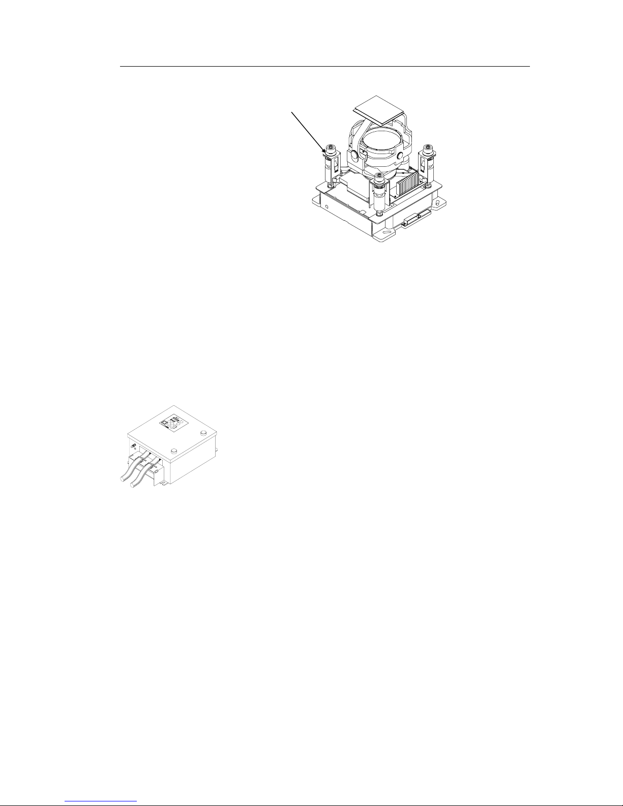
Note! A GC80 or GC85 system is identified by the labelling on top of
the Master compass’ case as shown on the figure below.
The labelling on the control unit is identical for both gyro
systems.
pfjo^a=d`UR
_lt
Page 11

SYSTEM OVERVIEW
20221529 / C 3
1.2 Precaution in use
The GC80/GC85 Expanded Gyro compass displays and outputs
bearing information. Although the system continually checks for
faults while the system is running, failures or malfunctions may
occur.
Any errors in input information will generate an alarm. These
errors may also cause large jumps in the output bearing from the
gyro compass. If this happens, any external equipment
depending on the bearing output from GC80/GC85 should be
operated manually or switched to other bearing sensors.
To assure long time safe operation, the following precautions
should be taken:
- Assure that the operator is familiar with the use of the
gyro compass
- Perform daily check to maintain normal system operation.
Refer MAINTENANCE, page 21 onwards
- If any unusual behavior is observed during daily
inspection, the cause should be found and corrected. If
necessary, the local Simrad dealer should be contacted
- If any alarm is generated, verify the reason for the alarm
Page 12
Simrad GC80/GC85 Expanded Gyro Compass
4 20221529 / C
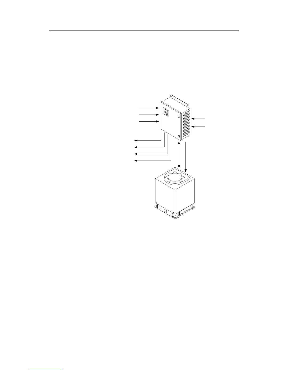
1.3 System components
A GC80/GC85 Expanded Gyro compass includes the following
units:
- Master Compass with Sensitive Element
- Expanded Control unit
Note! For details, refer TECHNICAL SPECIFICATION, page 63.
1.4 Bearing repeaters
GC80 and GC85 outputs step and serial signals used for
repeaters. Even when the gyro compass is supplied by the
emergency power supply, the connected repeaters will be driven
by the repeater backup function included in GC80/GC85.
If the serial output signal not is used for repeaters, the following
serial signal may be output:
- IEC61162-1 ed.2, close in comparison with NMEA0183
version 2.30 (4800 baud)
- IEC61162-2, based upon NMEA0183 version 2.30
(38400 baud, 9600 baud possible)
These signals may be set separately for each circuit.
For connection of repeaters, refer to wiring diagrams, page 74
onwards.
EXTERNAL HEADING SENSOR
GPS
SPEED
10 X NMEA
4 X 24V STEP
3 X ROT
110/220V AC POWER INPUT
MASTER
COMPASS
EXPANDED
CONTROL
UNIT
ALARM CONTACT
24V DC BACKUP SUPPLY
Page 13

USER INTERFACE
20221529 / C 5
2 USER INTERFACE
This section gives an overview of the GC80 Expanded
Control unit and the user interface.
Page 14
Simrad GC80/GC85 Expanded Gyro Compass
6 20221529 / C
2.1 GC80 Expanded Control unit
The Control unit includes the control panel for the gyro
compass.
A flush mount kit (part number 27101757) may be ordered from
Simrad for remote installation of the control panel. Refer Flush
mounting the control panel, page 35.
^i^oj
dvol
buq
afpm pbq
afj
i^jm
qbpq
^`h
bkq
pfjo^a=d`UM
POWER Button
mltbo
Used for switching the gyro system ON. The button will be lit to
indicate that power is applied to the system. Refer System Start-
up and Shut-down, page 10.
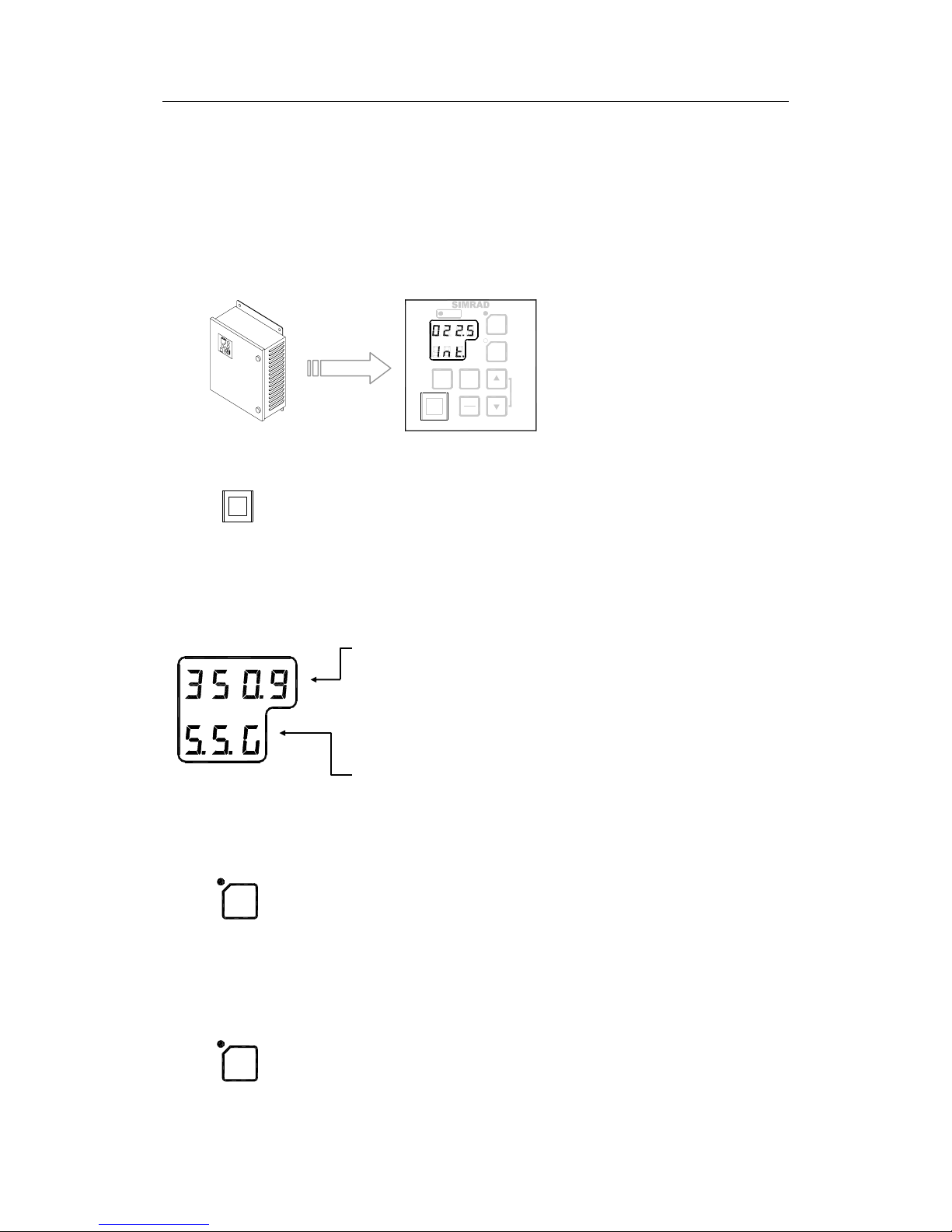
Display
The LCD displays data in two rows: the Data indicator row and
the Mode indicator row.
- The Data indicator consists of four 7-segments red
LEDs. The indicator is used for displaying the vessel’s
bearing, latitude and speed. Refer Displaying present
settings, page 13.
The Data indicator is also used for displaying alarm
codes as described from page 18 onwards.
- The Mode indicator consists of three 7-segments green
LEDs. The Mode indicator displays codes used for
identifying input type for bearing, latitude and speed.
GYRO Button
dvol
Used for selecting the gyro compass as the active heading
reference system. The status lamp is lit to indicate that the gyro
system is active.
Refer Selecting active compass, page 12.
EXT Button
buq
Used for selecting the external heading system as the heading
reference. The status lamp will be lit to indicate that the external
heading reference system is active.
Refer Selecting active compass, page 12.
Page 15
USER INTERFACE
20221529 / C 7
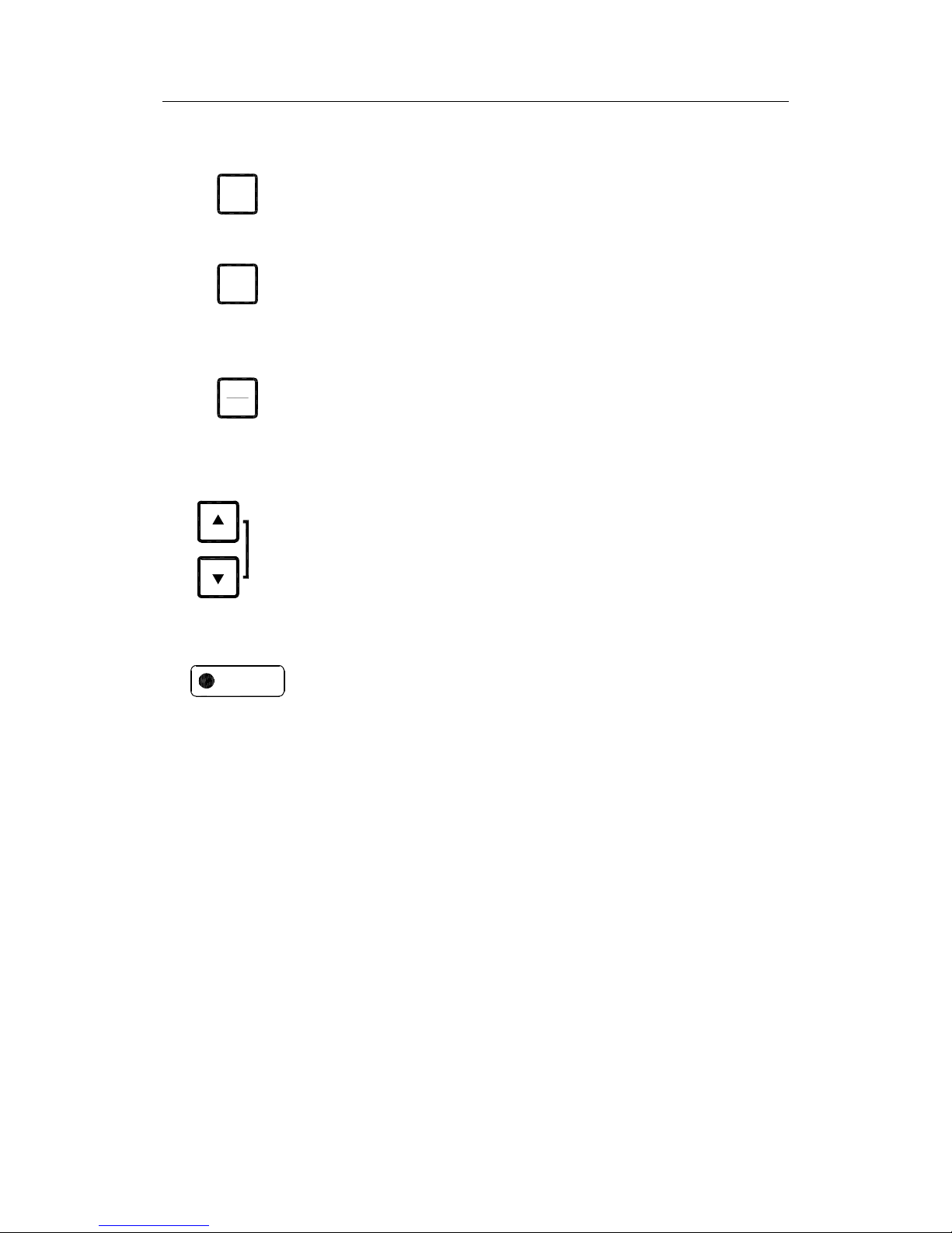
DISP Button
afpm
Used for displaying data on the LCD. Refer Displaying present
settings, page 13.
SET Button
pbq
Used for changing data and input systems. Refer System start-up
and software configuration, page 48 onwards.
ACK/ENT Button
^`h
bkq
Used for confirming a change in data and input systems. Refer
System start-up and software configuration, page 48 onwards.
The button is also used for acknowledging an alarm as described
in Acknowledging an alarm, page 20.
Arrow Buttons
afj
i^jm
qbpq
Used for increasing or decreasing a parameter value. Refer
System start-up and software configuration, page 48 onwards
Also used for lamp test and for setting the display illumination
as described in page 12.
Alarm Indicator
^i^oj
Used for indicating an alarm situation. Refer Alarm messages,
page 19.
Page 16

Simrad GC80/GC85 Expanded Gyro Compass
8 20221529 / C
THIS PAGE INTENTIONALLY LEFT
BLANK
Page 17

OPERATION
20221529 / C 9
3 OPERATION
This section describes the main operating procedure used
when operating the GC80/GC85 Expanded Gyro compass.
Page 18

Simrad GC80/GC85 Expanded Gyro Compass
10 20221529 / C
3.1 System Start-up and Shut-down
A GC80/GC85 Expanded gyro system is usually left with power
on. If the system has to be shut down and restarted, the
procedures in the following sections should be followed.
Start-Up
Caution Before the gyrocompass is turned into normal operation, it has
to be configured according to the description in System startup and software configuration, page 48 onwards.
mltbo
1 Turn ON the gyro system by pressing the POWER button
on the Control panel. The following start-up sequence will
be run:
Control unit type (GC80 Std, or GC85 HSc), SW version for
Control unit and for Master compass is displayed in rapid
succession. Examples of display text are shown below:
OR
GC80 CONTROL
UNIT
STD VERSION
GC80 CONTROL
UNIT
HIGH SPEED
VERSION
SW VERSION
CONTROL UNIT
SW. VERSION
MASTER COMPASS
dvol
2 If the rotor not was completely stopped when the POWER
button was pressed, a rotor break function will be activated
to stop the rotor.
Active rotor break is indicated with flashing display.
3 The sensitive element starts rising horizontally, and the
compass rotates 360° clockwise. The display shows
decreasing bearing as the compass is rotating.
dvol
4 When the rotation is stopped, start bearing is indicated
with flashing text in the display. The start bearing will be
the same as active bearing when the compass was turned
OFF.
Page 19

OPERATION
20221529 / C 11
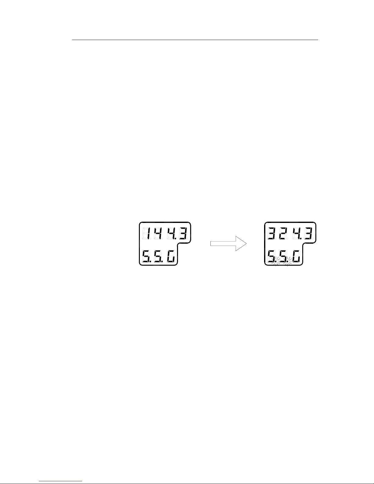
dvol
5 The indicated start bearing is accepted by pressing the
ACK/ENT button, or increased/decreased by using the
arrow buttons and then pressing the ACK/ENT button. If
no action is taken within 3 minutes, the start-up process
will continue with the indicated start bearing.
The bearing indication stops flashing when the start
bearing is accepted, while the lamp remains flashing.
6 The rotor will now start rotating, and reaches pre-described
number of revolutions after maximum 30 minutes.
dvol
7 When the rotor has reached full speed, the compass starts
the north seeking rotation. The display will now change to
show the compass’ actual heading, and from now on
bearing output will be available.
The lamp beside the GYRO button change from flashing to
steady light.
The GC80/GC85 will be settled within 3 hours when started
with a deviation angle less than 5°. With a larger deviation
angle, the compass will be settled within 4 hours.
Turning the Gyro compass OFF
mltbo
1 Press the POWER button on the Control panel. The light in
the POWER button will be switched off.
dvol
2 Repress the POWER button to activate the rotor break
function. The light in the POWER button will be lit again.
Active rotor break is indicated by:
- flashing display as shown on the figure
- a soft clicking sound heard from the gyrocompass
The rotor break function will be active for maximum 4
minutes.
Caution It is very important that the rotor break is activated to stop the
rotor rotation. If not, the sensitive element may be damaged!
mltbo
3 Press the POWER button again to shut down the
gyrocompass when both the data and the dot in the display
change from flashing to steady light.
The light in the POWER button will now be turned OFF.
Page 20
Simrad GC80/GC85 Expanded Gyro Compass
12 20221529 / C
3.2 Selecting active compass
If an external heading sensor is connected to GC80/GC85, it is
possible to switch between gyro and external heading sensor as
active steering sensor.
The gyro system will normally be used with the gyro compass
selected as active compass. An external heading sensor should
only be used as active compass when the gyro compass not is
working properly.
dvol
buq
+
^`h
bkq
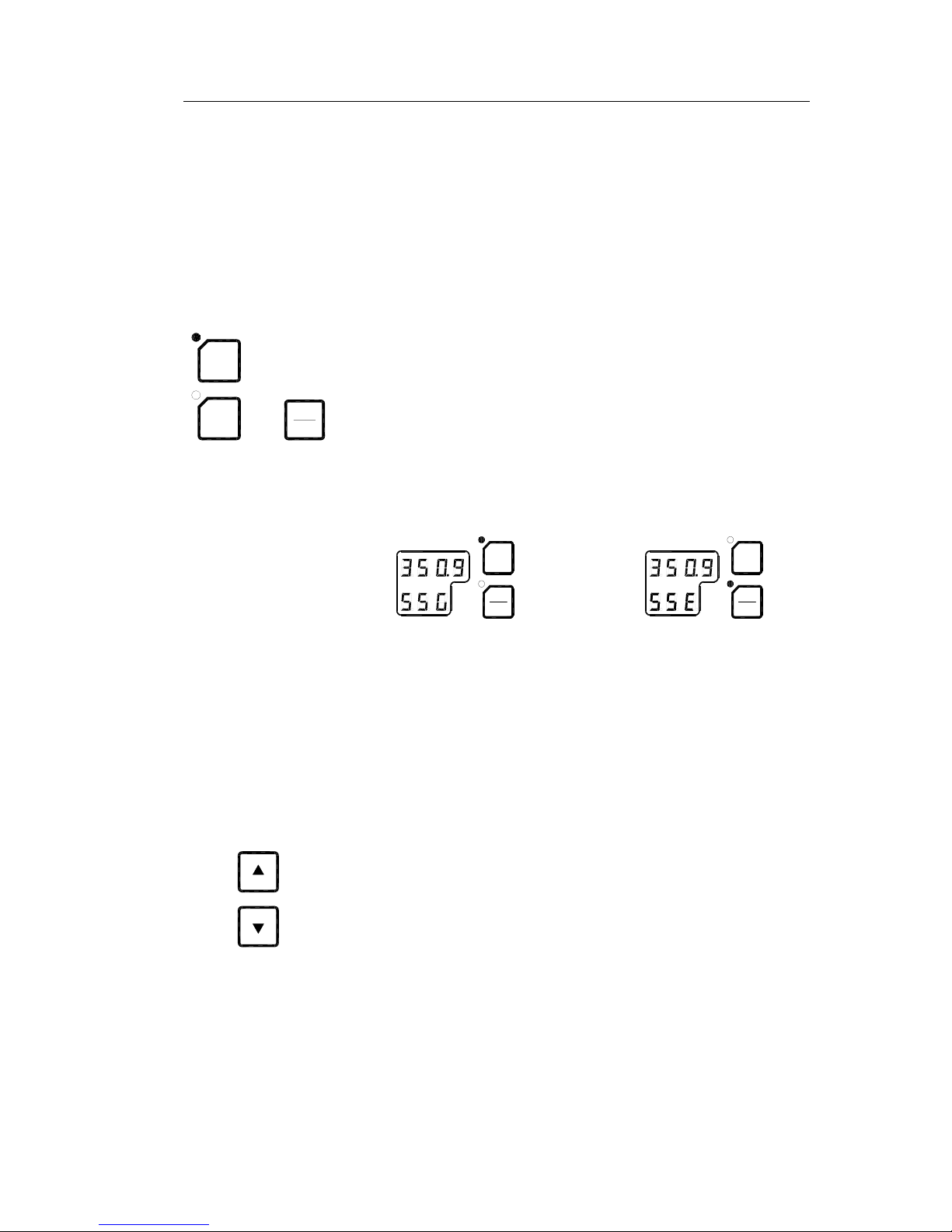
By pressing the GYRO or the EXT and the ACK/ENT buttons
simultaneously, the GC80/GC85 will toggle between using the
gyrocompass or an external sensor as active sensor.
When the active sensor is changed, an audible alarm will sound
three times.
Active compass is identified with light in the button’s indicator
lamp, and with active compass type in the LCD as shown in the
figures below.
dvol
j^d
buq
dvol
j^d
buq
GYRO COMPASS SELECTED AS
ACTIVE STEERING SENSOR
EXTERNAL HEADING SENSOR
SELECTED AS
ACTIVE STEERING SENSOR
WARNING Changing active compass may result in large
change of true bearing. No changes should
therefore be made when the system is in
operation.
3.3 Adjusting dimming level
afj
The display illumination and the light intensity in the indicator
lamps can be increased or decreased in 5 steps by pressing the
arrow buttons.
When the illumination is set to lowest level, a faint light is still
present in the display, Alarm indicator, status lamp and Power
button.
Panel lamps and display segments may be tested by pressing
both arrow buttons simultaneously. All lamps and display
segments will be lit, and a short audible alarm will be activated.
Page 21
OPERATION
20221529 / C 13
3.4 Displaying present settings
afpm
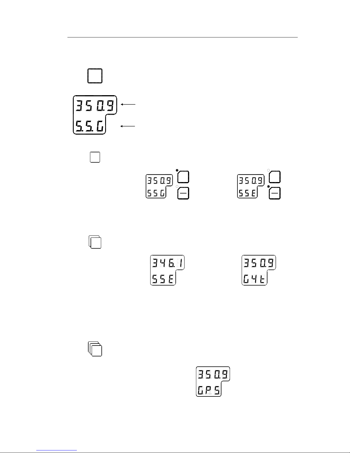
When pressing the DISP button on the GC80 Control unit, the
system will loop through a display sequence showing present
settings for the system.
- The first row in the display will show the value
- The second row displays code used for identification
afpm
True output bearing from active compass
dvol
j^d
buq
dvol
j^d
buq
GYRO COMPASS SELECTED AS
ACTIVE STEERING SENSOR
EXTERNAL HEADING SENSOR
SELECTED AS
ACTIVE STEERING SENSOR
afpm
Bearing from passive sensor
EXTERNAL HEADING SENSOR
IS PASSIVE STEERING SENSOR
GYRO COMPASS IS
PASSIVE STEERING SENSOR
Note! This display is only available when an external sensor is
connected to the GC80/GC85.
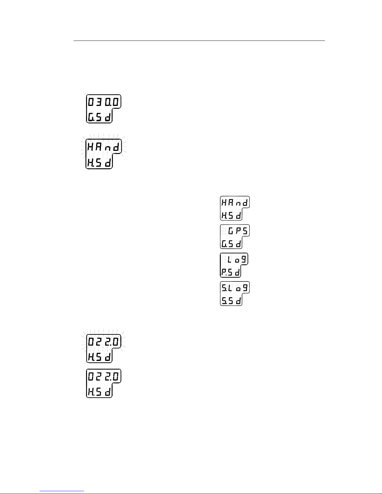
afpm
Gyro compass bearing without correction, together with active
speed input system indication (GPS, Manual, Log or Serial
Log)
Page 22
Simrad GC80/GC85 Expanded Gyro Compass
14 20221529 / C
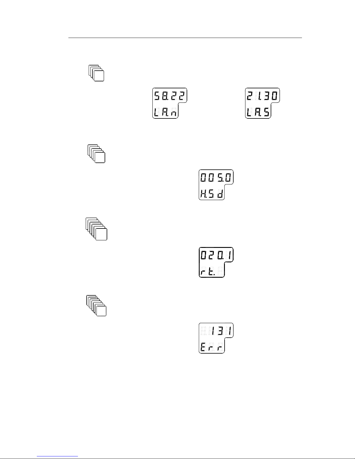
afpm
Latitude for the vessel’s current position. Value indicated as
North (n) or South (s) latitude
NORTH LATITUDE SOUTH LATITUDE
afpm
Vessel speed. GPS, Manual, Log or Serial Log may be selected
as speed input system
afpm
Rate of turn in °/min.
afpm
Error codes (up to 4), and error indication.
Page 23

OPERATION
20221529 / C 15
3.5 Confirming present settings
After the GC80/GC85 is configured according to the System
start-up and software configuration, described in page 48
onwards, it should not be necessary to adjust any settings when
operating the gyro compass.
However, if an error is reported in any of the input systems, it
may be necessary to switch to a different input system.
True bearing
Make sure that the gyro compass is selected as active compass.
Refer Selecting active compass, page 12.
dvol
Confirm that the gyro compass’s displayed true bearing is the
same as a known target or astronomical observation.
If there is any difference, adjust the bearing according to
Adjusting True heading, page 53.
Latitude
Press the DISP button until the vessel’s latitude is displayed.
The displayed latitude value is calculated based on the vessel’s
true bearing and the vessel’s actual speed. Refer setting the
latitude input system and speed input system, page 51 onwards.
- If GPS is selected as latitude input system, the latitude
obtained from the GPS is displayed on the LCD. Confirm
that the displayed latitude is the same as indicated on the
GPS indicator.
- If GYRO is selected as latitude input system and other
than MANUAL selected as the vessel’s speed input
system, the latitude will be automatically updated. In this
case, the indicated latitude should be confirmed every 4ht
hour when the vessel is in harbor. If there is any difference
between the displayed value and the vessel’s actual
latitude, the value should be adjusted according to Setting
the Latitude input system, page 51.
Note! When GYRO is selected as latitude input system and MANUAL
is selected as the speed input system, the indicated latitude value
will not be updated.
Page 24

Simrad GC80/GC85 Expanded Gyro Compass
16 20221529 / C
Speed
The GC80/GC85 gyro compass calculates bearing based on the
speed and latitude information that is input to the gyro system.
Any errors in speed input will therefore cause incorrect true
bearing from the gyro compass.
Press the DISP button until the vessel’s speed information is
displayed.
Confirm in 4 hours intervals that the displayed speed is the same
as the vessel’s actual speed.
Any discrepancy between displayed speed and actual speed is
corrected as described in Setting the Speed input system, page
52.
Speed error correction
Any gyro compass will generate a heading error caused by
vessel speed and the earth rotation. GC80/GC85 calculates this
error based on latitude and speed input information, and corrects
automatically the bearing signal output. If no speed information
is available, the gyro compass will output a heading error either
westwards or eastwards depending on the vessel’s course.
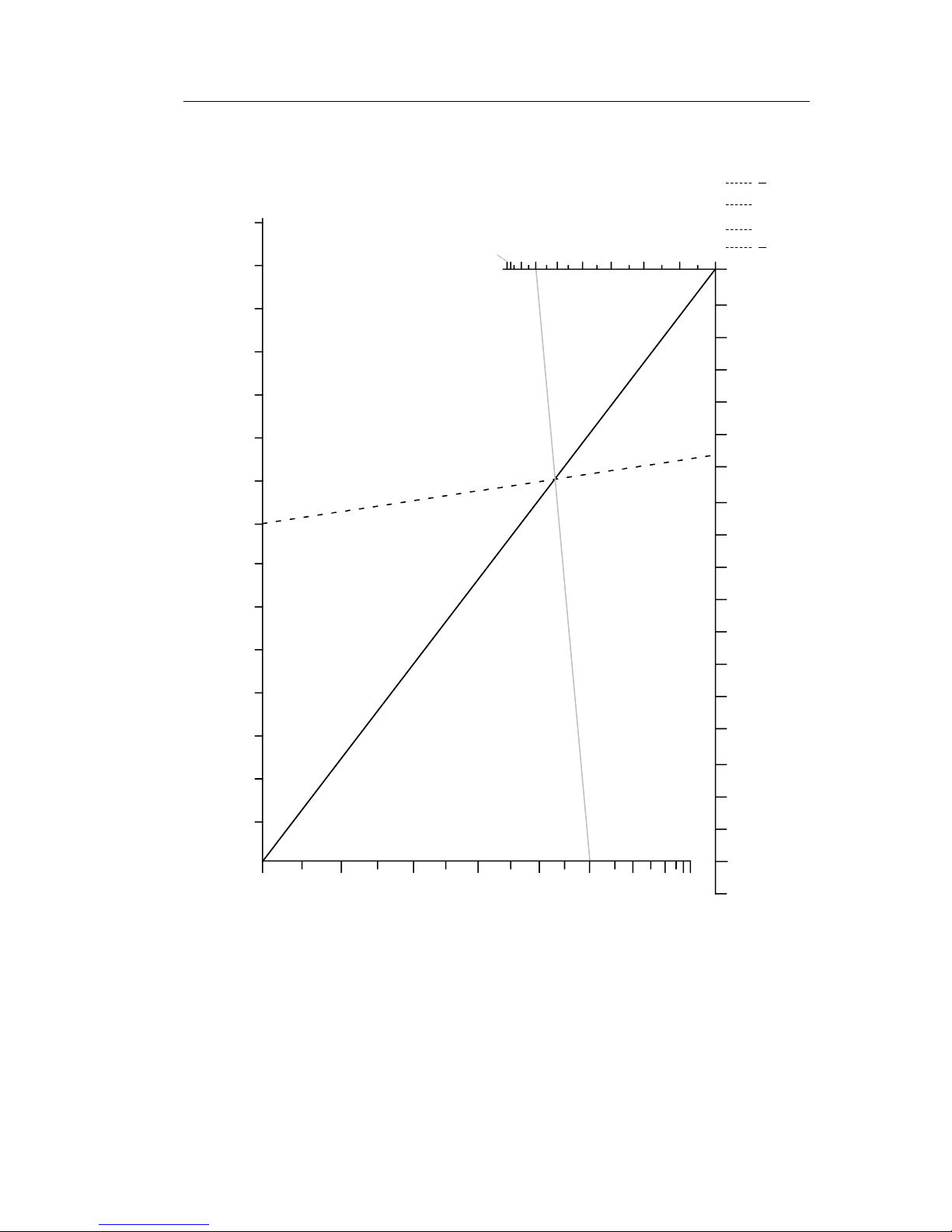
If speed information is unavailable, the figure on next page
could be used for manually calculating the heading error.
In this figure, the following values are used as example:
- Latitude: 40°
- Vessel speed: 16 knots
- Vessel heading: 30°
The heading error is found by:
1 Drawing a line between the latitude and the vessel heading
(shown with gray line on the figure)
2 Drawing a straight line (broken line in the figure) between
the vessel speed and the point where the latitude/heading
line intersects with the solid black line in the figure.
In the example above, the figure shows a speed error of appr.
1.1°, and the true bearing should then be 30°-1.1° = 28.9°.
Note! When the course is within 270° - 0° - 90°, true heading is found
by subtracting the speed error from the compass heading.
If the course is within 90° - 180° - 270°, true heading is found
by adding the speed error to compass heading.
Page 25
OPERATION
20221529 / C 17
VESSEL HEADING (degree)
VESSEL SPEED (knots)
30
28
26
24
22
20
18
16
14
12
10
8
6
4
2
0
90 80 70
60 50 40 30 20 10
3.8
3.6
3.4
3.2
3.0
2.8
2.6
2.4
2.2
2.0
1.8
1.6
1.4
1.2
1.0
0.8
0.6
0.4
0.2
0
0
90 - 90 - 270 - 270
80 - 100 - 260 - 280
0 - 180 - 190 - 0
70 - 110 - 250 - 290
60 - 120 - 240 - 300
50 - 130 - 230 - 310
40 - 140 - 220 - 320
30 - 150 - 210 - 330
20 - 160 - 200 - 340
10 - 170 - 190 - 350
(+)
(+)
( )
( )
SPEED ERROR (degrees)
LATITUDE (degrees)
Page 26
Simrad GC80/GC85 Expanded Gyro Compass
18 20221529 / C
3.6 Pendulum function
GC80/85 software includes a pendulum function that enables the
heading to be changed by 180°.
The heading change is activated by closing a potential free
contact connected between TB1, pin 71 and 72 on the GTERM
board in GC80/85 control unit.
Note! To identify the function, S2-4 on the SCC board has to be set to
ON. Refer DIP switch settings on SCC board, page 91 onwards.
When the switch is activated, the following actions are
performed:
- The compass heading and repeaters start to change
towards the new 180° shifted heading
- An acoustic alarm sounds 5 times
- The dots in the indicator field in the display starts flashing.
These will remain flashing for as long as the pendulum
function is active.
Normal compass operation is resumed by opening the closed
potential free contact. The function is indicated by the same
acoustic alarm, and the flashing dots returns to fixed illuminated
dots.
Page 27
OPERATION
20221529 / C 19
3.7 Alarm messages
The GC80/GC85 system will continually check for faults while
the system is running.
If a fault occurs, an alarm code will be displayed in the LCD, the
Alarm lamp will be flashing, and an audible alarm will be
activated.
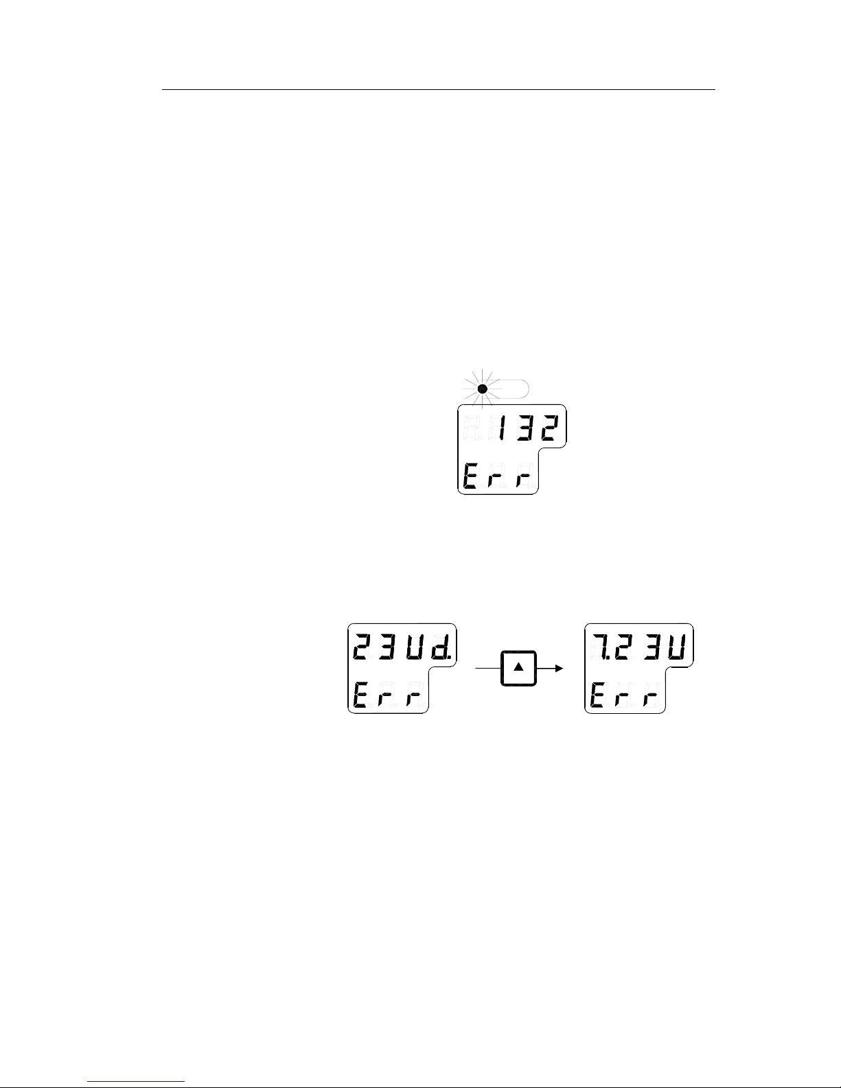
Up to 4 alarm codes may be displayed in the LCD to indicate
that several alarm situations are present. The last activated alarm
will be displayed on the right side of the display. The figure
shows that alarm with code 1, 3 and 2 were generated in that
order.
^i^oj
If more than 4 alarms are active, this will be indicated with a dot
behind the last number as shown on the figure below. Further
alarm codes may then be displayed by pressing the “arrow up”
button.
The example shows that alarm code 2, 3, U, d and 7 were
activated.
Caution When an alarm is generated, bearing information from the
GC80/GC85 may not be present or may have large error. Any
equipment using bearing information from the gyro compass
should therefore immediately be operated according to the
equipment’s emergency operating procedure.
Page 28

Simrad GC80/GC85 Expanded Gyro Compass
20 20221529 / C
Acknowledging an alarm
^`h
bkq
An alarm is acknowledged by pressing the ACK/ENT button on
the control panel, or on an external acknowledge button is this is
installed.
- The audible alarm will be silenced
- If the alarm situation has disappeared, the alarm lamp will
be switched off, and the alarm code will be removed from
the LCD
- If the alarm situation continues, the alarm lamp will switch
from flashing to steady light. The LCD will return to show
true bearing with flashing numbers to indicate that the
bearing may have large errors
An alarm code for an active error may be recalled by pressing
the DISP button until the alarm display is shown. It is possible
to recall any alarm code in the LCD for as long as the alarm
situation is present.
The Complete alarm code list section, page 109, has a complete
list of alarm codes.
Buzzer silence only
By installing an external acknowledging switch, it is possible to
silence the buzzer while the alarm code remains in the display.
Install the switch to the control unit according to the Wiring
diagram on page 74 onwards.
Note! Could only be used if no pendulum switch is installed!
Page 29

MAINTENANCE
20221529 / C 21
4 MAINTENANCE
This section holds descriptions for maintenance procedures
that should be performed by the system operator.
The section also includes a detailed description for how to
replace the sensitive element and the fuses.
Page 30

Simrad GC80/GC85 Expanded Gyro Compass
22 20221529 / C
4.1 General
All units in the GC80 system are designed for optimum safety
and reliability. However, a limited amount of preventive
maintenance should be performed to verify safe operation and
durability.
If any strange motion, smell, sound or heat is generated from
any unit, a Simrad dealer shall be contacted.
4.2 Precautions
Touching internal parts may cause electric chock if power is
connected to the system, even if the POWER button is turned
OFF. Do not touch any terminal board or power supply unit
when maintaining and checking the system. If necessary,
disconnect the power cable from the Control unit.
Electrostatic charges may damage components on the circuit
boards inside the units. Always wear a correctly connected
earthing strap when opening the units.
4.3 Cleaning the operator panels and the cabinet
surface
Use a vacuum cleaner with a soft brush to avoid damage to the
buttons and the panel. If required, clean the buttons and panel
with a non-abrasive cloth moistened with mild soap solution.
4.4 Checking the connectors
The connectors should be checked by visual inspection only.
Push the connector plugs into the connector. If the connector
plugs are equipped with a lock, ensure that this is in correct
position.
4.5 Checking mechanical installation
Vibration and chock may cause mechanical parts to loosen. All
fastening screws should therefore regularly be checked and
eventually tightened.
Page 31

MAINTENANCE
20221529 / C 23
4.6 Preventive maintenance intervals
Local evaluations should be made to determine site-specific
maintenance intervals.
ACTION INTERVAL RECOMMENDED
Confirm that the value of each
repeater synchronizes with the
displayed true bearing on the
Operator panel.
Daily
Confirm that the displayed
latitude and speed is according to
the vessel’s actual latitude and
speed.
Daily
Check connectors Every six month
Tighten fastening screws Every six month
Clean panels and cabinet Once a year or as required
4.7 Replacing the Sensitive element
Caution The Sensitive element should only be replaced by authorized
Simrad personnel.
Note! A special tool (Simrad part no. 44174449) is required when
installing the Sensitive element. This tool is delivered together
with the gyro, and the sensitive element should not be installed
without using this tool.
Mechanical installation
Caution Use extreme caution when handling the Sensitive element! Do
not tilt the element. It is filled with oil and the top is open.
1 Ensure that the power is disconnected from the Control
unit.
2 Remove the four screws securing the compass case, and
lift the case carefully upwards and away.
3 Loosen the screw on the plug-holder on the Sensitive
element, and disconnect the plug.
Page 32

Simrad GC80/GC85 Expanded Gyro Compass
24 20221529 / C
4 Remove the four screws securing the Sensitive element.
Tilt the Horizontal ring to the side where the plug is
located, and carefully remove the element from the
compass.
5 Place the defective Sensitive element in its original
package, and put the rubber tube on top of the element.
6 Re-install the plug-holder on the defective Sensitive
element.
7 Lift the new element carefully from its package, and
remove the rubber tube on top of the element.
Note! The package and the rubber tube should be kept for re-use if the
Sensitive element has to be sent to factory for service!
Page 33

MAINTENANCE
20221529 / C 25
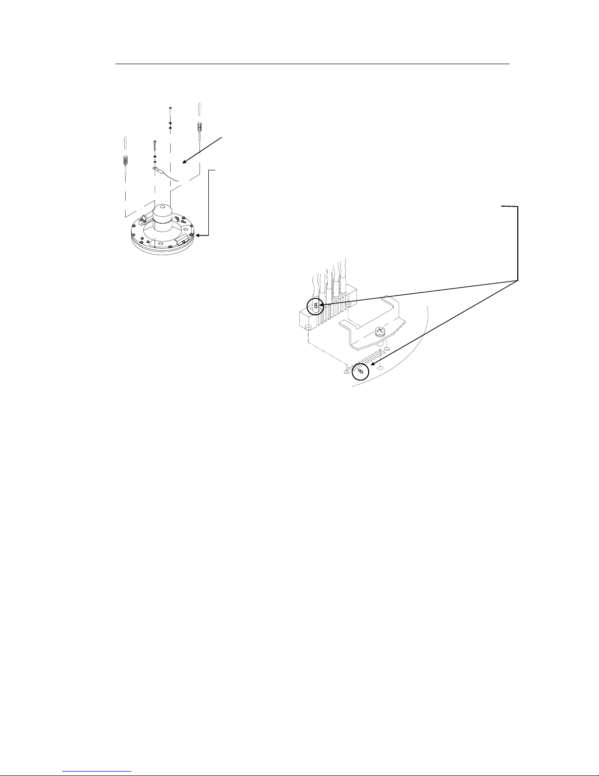
8 Tilt the Horizontal ring to the side where the plug is
located, and carefully put the sensitive element into the
ring.
- The socket on the Sensitive element should be located
right above the plug attached to the Horizontal ring.
9 Position the Sensitive element on the Horizontal ring by
putting the assembly jigs into the holes as indicated on the
figure below. Observe the rings on the jigs to ensure
proper positioning. Insert and fasten the two screws in the
other holes.
ASSEMBLY JIG
WITH 1 CIRCLE
ASSEMBLY JIG
WITH 2 CIRCLES
Page 34
Simrad GC80/GC85 Expanded Gyro Compass
26 20221529 / C
10 Replace the assembly jigs with the two remaining screws
after placing the ground wire as shown on the figure.
11 Loosen the screw on the plug-holder on the Sensitive
element, and lift the holder 2-3 mm upwards.
12 Connect the plug to the connectors on the Sensitive
element’s pcb according to the labelling on the pcb and on
the wires. Make sure that the pin guides on the plug are
properly entered, and that the wires are not twisted.
13 Firmly tighten the screw on the holder.
Page 35

MAINTENANCE
20221529 / C 27
Verifying the element’s tilt angle
1 Tilt the Sensitive element by hand towards the level tool
on the Horizontal ring and keep it tilted for approximately
1 minute. Remove the pressure and observe that the tilt
angle remains at:
- GC80: 15° to 19°
- GC85: 18° to 22°
The tilt angle is indicated on the figures below.
1
5
°
1
9
°
Max and min tilt angle for GC80 std system
1
8
°
2
2
°
Max and min tilt angle for GC85 High Speed system
Note! The tilt angle shown above is correct for cold condition. The
angle may change when the element has reached normal
operational temperature!
Page 36

Simrad GC80/GC85 Expanded Gyro Compass
28 20221529 / C
2 If the tilt angle is incorrect, weight disks must be adjusted
by moving weights from one side to the other. After
adjustments, wait for 2 minutes before the tilt angle
verification is repeated.
Caution The sensitive element must have equal number of weight disks
on both weight points on the tilting side (north and south
side)!
3 Carefully rotate the Horizontal ring at least one complete
rotation. Verify that all movable parts will rotate without
making any contact with mechanical or electrical
components.
Parameter updates
When a sensitive element is replaced, parameters for the new
element have to be loaded into the GC80 Control unit before the
gyro compass is started. This is done from the Extension menu
as described below.
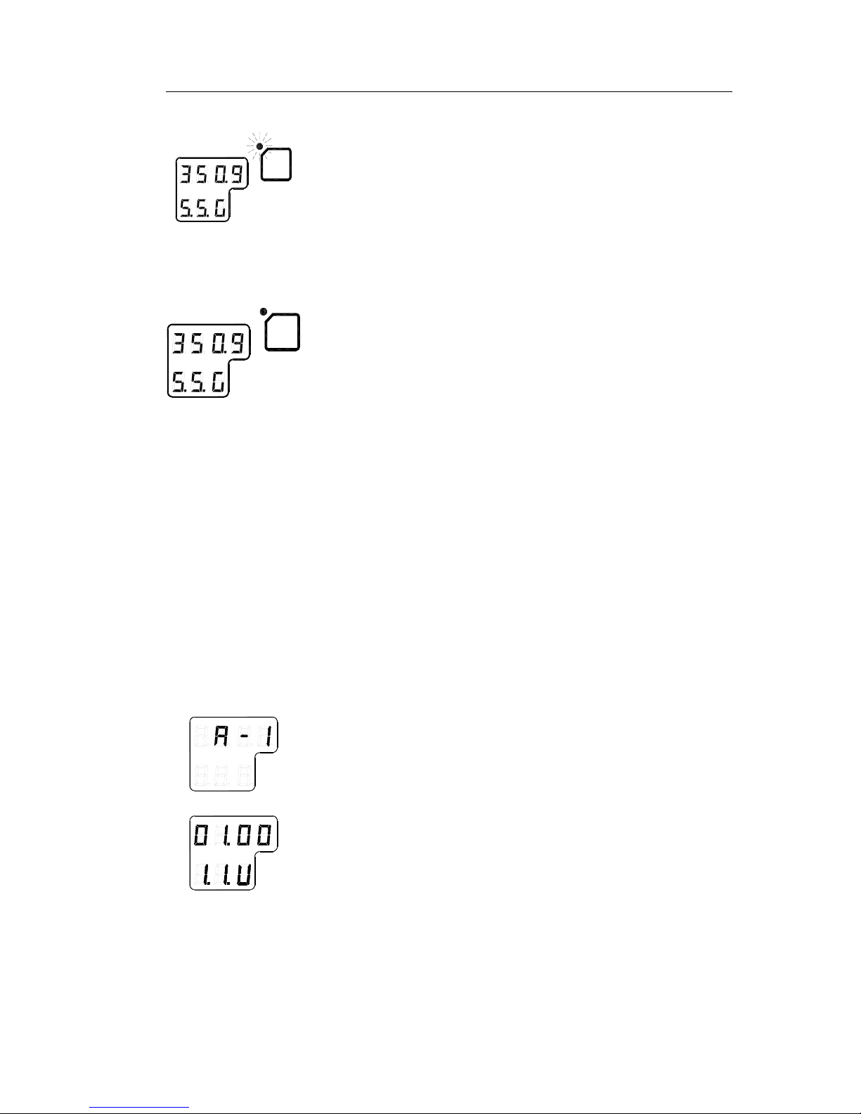
1 Enter the Extension menu by pressing and holding the SET
button and the ACK/ENT buttons simultaneously for at
least 3 seconds.
Main category A-1 will be displayed.
2 Press the SET button to enter the sub-category loop. Sub-
category 1.1.U and its parameter values will be displayed.
3 Use the arrow buttons to increase or decrease the
parameter value until the value is according to the labelling
for the new sensitive element.
4 Confirm the entry by pressing the ACK/ENT button. The
display will return to sub-category 1.1.U, and the data will
be transferred to the gyro immediately.
5 Press the DISP button again to select sub-category 1.6.t,
and use the arrow buttons to increase or decrease the
parameter value until the value corresponds with the
parameter for the new sensitive element. Confirm the entry
by pressing the
ACK/ENT button.
Page 37

MAINTENANCE
20221529 / C 29
6 Exit the sub-category by pressing the SET button, and then
exit the Extension main category by pressing and holding
the SET and ACK/ENT buttons simultaneously for at least
3 seconds.
For more information about the Extension menu, see
ADVANCED SETTINGS, page 55 onwards.
Balancing the Horizontal ring
After the Sensitive element has been replaced, the gyro compass
should be started as described on page 10.
When the compass has been running continuously for at least 2
hours, the horizontal ring should be adjusted.
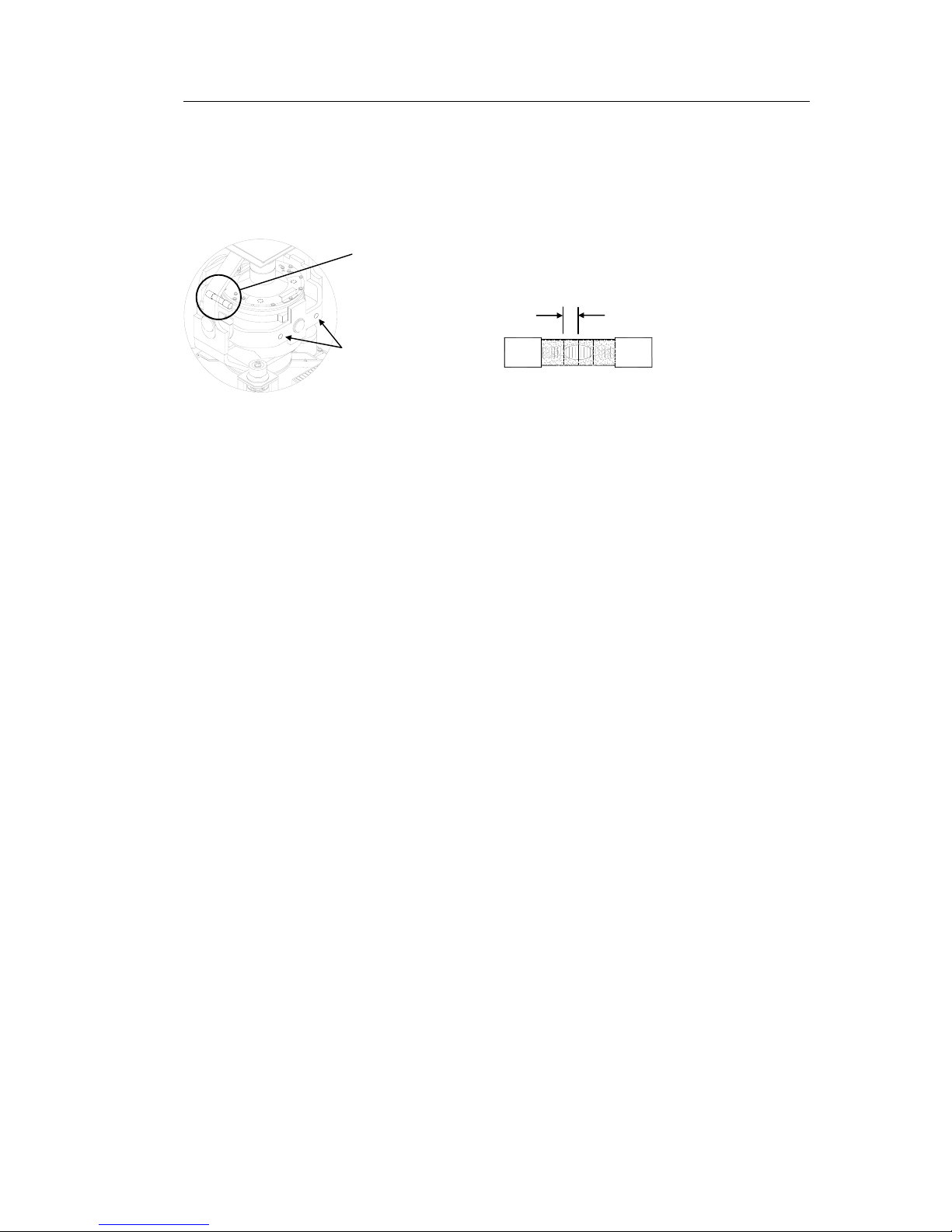
1 Locate the reference level tool on the horizontal ring, and
check that the level bubble is within +/-10 minutes from
the center. Each division equals 2 minutes.
2 If the level bubble not is within this limit, add or remove
weights from the horizontal ring until it is level.
Note! It is important that the total number of weights on the horizontal
ring are as few as possible.
3 Let the compass run for at least 20 minutes before the
level is rechecked and eventually confirmed.
WARNING If the horizontal ring is tilted more than +/-
10’, a bearing error will be generated!
10 minutes
Page 38

Simrad GC80/GC85 Expanded Gyro Compass
30 20221529 / C
4.8 Replacing the Fuses
WARNING Before a fuse is replaced, ensure that both
the main power and the emergency power is
disconnected from the unit.
Use the procedures described in the following pages when
replacing the fuses.
Master Compass
Fuse F1 is located inside the fuse holder in the front of the
Master compass.
1 Open the fuse holder by pressing and turning the fuse
holder edge counter-clockwise with a screw driver.
2 Replace fuse F1, and close the holder by turning it
clockwise.
F1 (12A)
Page 39

MAINTENANCE
20221529 / C 31
Expanded Control unit
FUSE NO CAPACITY TB-NO SIGNAL DESCRIPTION
F1 TB2-5 1R24+ Power supply for ch.1 serial repeater
F2 TB2-10 2R24+ Power supply for ch.2 serial repeater
F3 TB2-15 3R24+ Power supply for ch.3 serial repeater
F4 TB2-20 4R24+ Power supply for ch.4 serial repeater
F5 TB2-29 5R24+ Power supply for ch.5 serial repeater
F6 TB2-34 6R24+ Power supply for ch.6 serial repeater
F7 TB2-39 7R24+ Power supply for ch.7 serial repeater
F8 TB2-44 8R24+ Power supply for ch.8 serial repeater
F9 TB1-31 9R24+ Power supply for ch.9 serial repeater
F10 TB1-36 10R24+ Power supply for ch.10 serial repeater
F11 TB2-61 Power supply for ch.1 step motor repeater
F12 TB2-66 Power supply for ch.2 step motor repeater
F13 TB2-71 Power supply for ch.3 step motor repeater
F14
1A
TB2-24 Power supply for ch.4 step motor repeater
F15 15A J9, 1-6 Repeater power supply
F16 J4, 23-27 Power supply for SCC and SIFC boards
F17
3.15A
J9, 15-16 Power supply for HDM part
F101 6.3A TB101 Main power supply
F102 20A TB101 Emergency power supply
Page 40

Simrad GC80/GC85 Expanded Gyro Compass
32 20221529 / C
F15
F16
F11
F10
F2
F1
F5
F6
F7
F9
F3
F12
F8
F4
F13
F14
F17
WARNING Make sure that the main power switch SW1 is
turned OFF before any fuses are replaced!
Note! The fuses in the Expanded Control unit are open glass type and
may be damaged if handles with force.
1 Pull the broken fuse up from the holder.
2 Re-install a new fuse by carefully pushing it into the
holder. When correctly located, it should be fixed 1-2mm
above and parallel with the mounting level.
SW1
MAIN
POWER
SWITCH
F101
F102
F3, F4, F8,
F13, F14
F17
F15
F1 - F2, F5 - F7,
F9 - F11
F16
Page 41

INSTALLATION
20221529 / C 33
5 INSTALLATION
This section is a reference guide for correctly installing and
configuring the GC80/85 Gyro Compasses.
Page 42

Simrad GC80/GC85 Expanded Gyro Compass
34 20221529 / C
5.1 Unpacking and handling
A GC80/85 Gyro compass consist of the following units:
- Master compass
- Sensitive element
- Control unit
- Spare part kit
- Mounting jigs
- Documentation
The sensitive element is shipped from the factory packed
separately in foaming phenylethene to protect it from shock and
vibration. The final assembly of the sensitive element into the
Master compass have to be done when the Master compass is
mounted onboard the vessel. Refer page 43.
Note! It is recommended to keep the packing material for the Sensitive
element. This original packing should be used if the element is
sent to the factory for service or repair.
Care should be taken when unpacking and handling the
equipment. A visual inspection should be made to see that the
equipment has not been damaged during shipment and that all
components and parts are present.
5.2 Mechanical installation
The units included in the GC80/GC85 system should be
mounted with special regard to the units’ environmental
protection, temperature range and cable length. Refer Technical
specifications, page 63 onwards.
Note! A special tool (Simrad part no. 44174449) is required when
installing the Sensitive element. This tool is delivered together
with the gyro, and the sensitive element should not be installed
without using this tool.
Page 43

INSTALLATION
20221529 / C 35
Control unit
The Control unit is bulkhead mounted by using 4 bolts as shown
in the illustration.
Flush mounting the control panel
The control panel may be removed from the Control unit and
mounted in a remote location by using the optional flush
mounting kit (part number 27101757).
The flush mounting kit includes:
- 1 flush mounting panel
- 4 corners
- 4 mounting screws
- 1 blind cover
In addition to this kit, an optional control panel cable must be
ordered. The cable is available in three different lengths:
- 5m (part no. 44170736)
- 10m (part no. 44170744)
- 15m (part no. 44170751)
Use the following procedure when remotely mounting the
control panel:
1 Open the control unit, and remove the wiring strips
holding the control panel’s cable.
2 Disconnect the cable’s grounding wires (labelled FG)
from the control panel and from the PWB SCC board in
the Control unit.
CONTROL
PANEL
GC80/85
REMOTE PANEL
Page 44

Simrad GC80/GC85 Expanded Gyro Compass
36 20221529 / C
3 Disconnect the plugs and remove the control panel’s
cable.
4 Loosen the 4 nuts holding the control panel, and remove
the panel. These nuts are to be re-used when fastening the
control panel to the flush mounting panel.
5 Insert the control panel in the flush-mounting kit from the
front side as shown on the figure. Fasten the panel with the
4 nuts.
6 Insert the plug on the optional control panel cable, and
connect the grounding wire.
7 Mount the cover on the back side.
8 Fasten the cable to the cover by a wire strip.
9 Slide the control panel cable through the cable inlet, insert
the plug in PWB SCC board and connect the grounding
wire. Secure the cable to the control unit by a wire strip.
10 Insert the blind cover in the Control unit by using the 4
bolts included in the kit.
Page 45
INSTALLATION
20221529 / C 37
Master compass
Select a mounting location where the deck is horizontally, flat
and with little vibration, and where the pitch/roll motion is as
small as possible.
It is also important to select a mounting location with sufficient
space for installation and service. Refer dimensional drawing,
page 72.
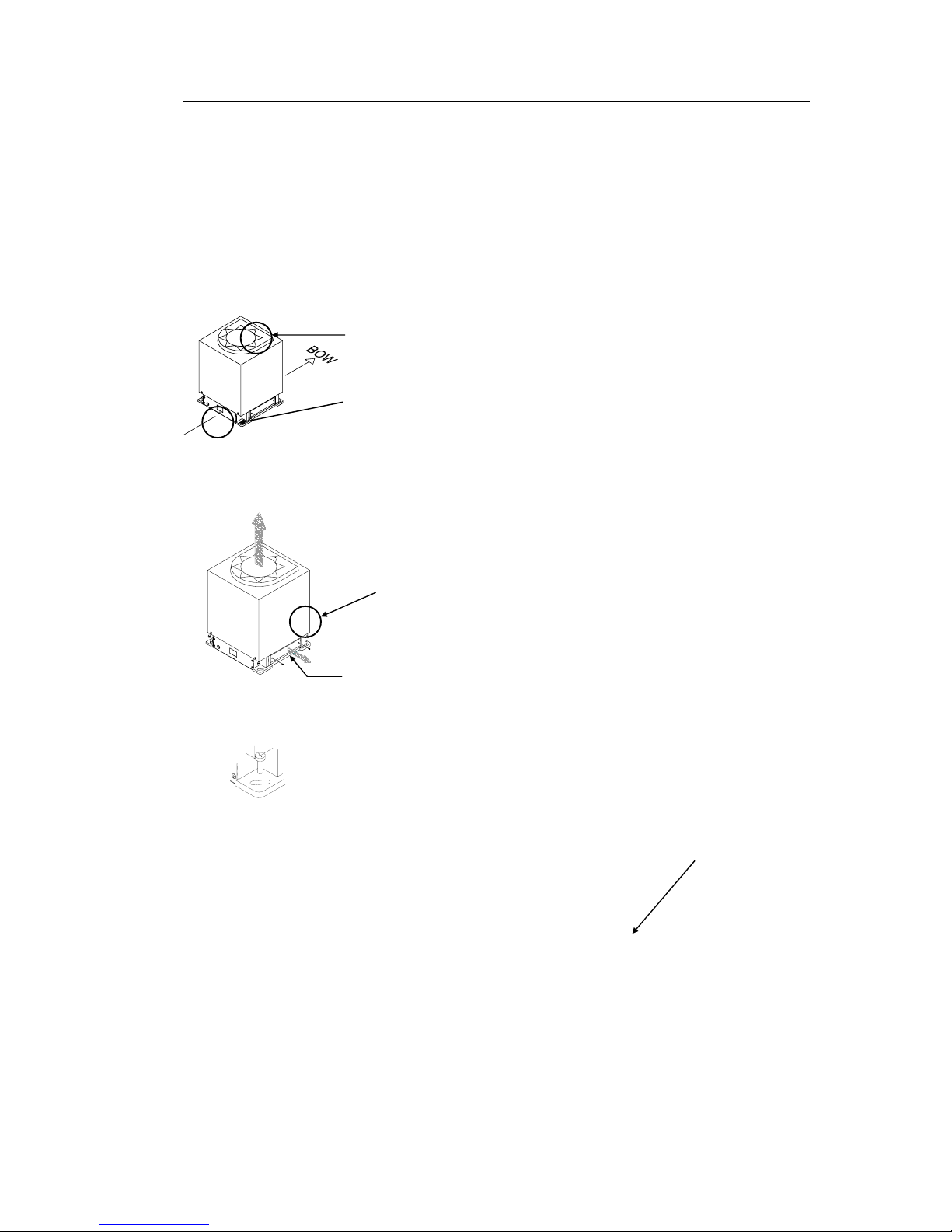
1 Locate the compass on or parallel to the vessel’s
horizontal centerline, with the bow indication on the top of
the case pointing towards the vessel’s bow.
2 Use the datum line in the front and back to of the compass
to line up the unit.
- It is possible to compensate for a small mounting offset
by using the heading offset feature as described in
Adjusting True heading, page 53.
3 Remove the four screws holding the compass case, and lift
the case carefully upwards and away.
4 Remove the cable inlet cover.
5 Fasten the compass to the deck with four bolts. The bolts
should be located in the center of the trails for later to be
able to adjust the compass direction when the heading is
tuned in. Refer Adjusting True heading, page 53.
6 Remove strips and foam rubber from the chock absorbers,
together with all strips used for securing moving parts
during transportation.
Page 46
Simrad GC80/GC85 Expanded Gyro Compass
38 20221529 / C
Note! The foam rubber should be kept for re-use if the Master compass
has to be sent to factory for service!
5.3 Cabling
Note! No cables are included when the gyro system is delivered from
factory.
The wiring diagram on page 74 onwards includes cable
specification for all cables that is to be used.
Connect power and signal cables according to the wiring
diagram on page 74 onwards.
To avoid that vibration should cause the cables to loose
connection, the cables could be fastened to the fixing device by
using wire straps as illustrated on the figure.
Page 47
INSTALLATION
20221529 / C 39
Power supply
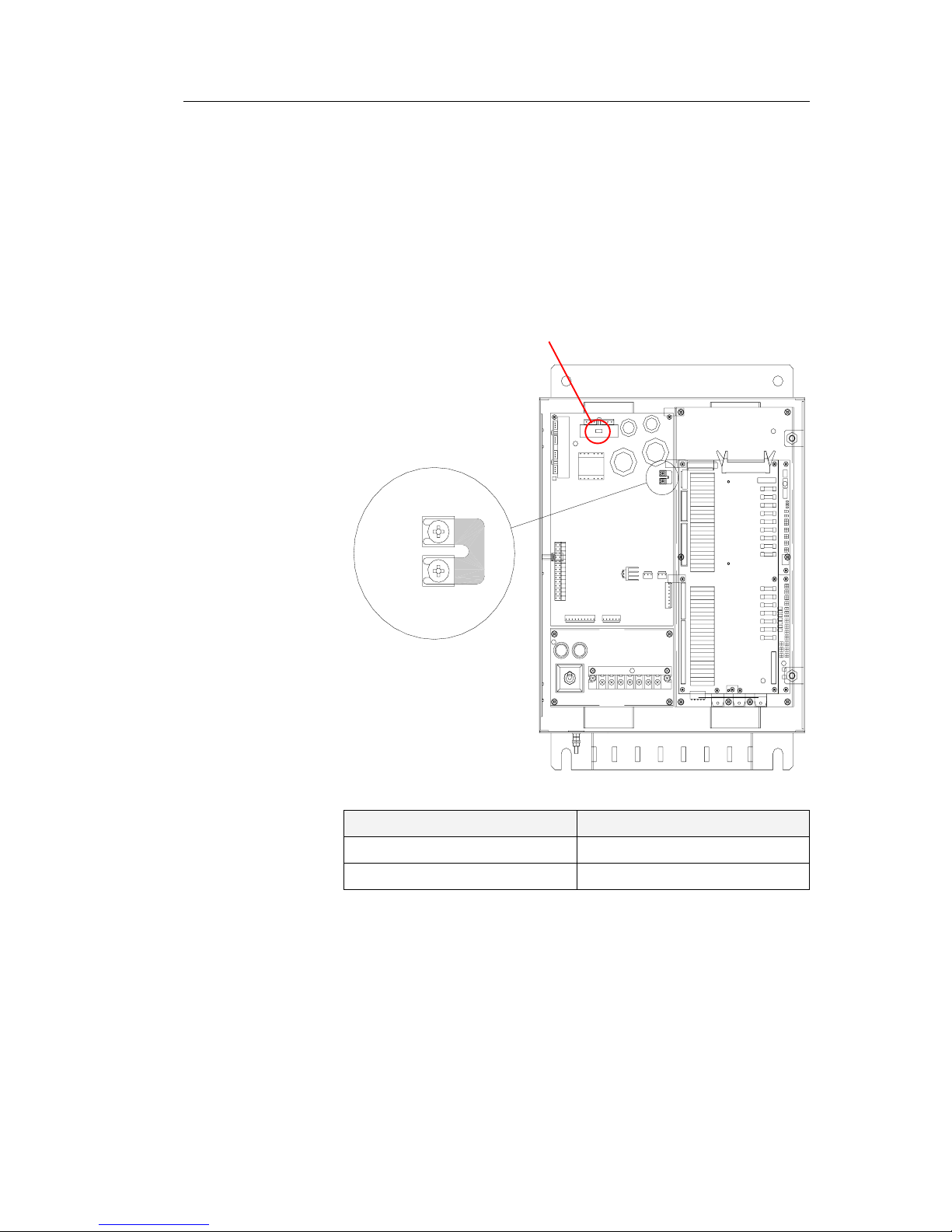
GC80/GC85 is to be supplied with 110 or 220V AC.
When delivered from factory, the system is set up for 220V AC.
If the system is to be supplied with 110V AC, a strap on the
GPOWER board has to be added according to the figure and the
table below.
Note! Replace the 220V AC label with a 110V AC indication if the
compass is set up for 110V AC power supply!
TB3
TB4
TB4
TB3
TB3 – TB4 VOLTAGE
Open 220V AC (default)
Short 100/110/115V AC
Page 48

Simrad GC80/GC85 Expanded Gyro Compass
40 20221529 / C
5.4 Grounding the units
All units in the GC80/GC85 system should have a proper
ground connection from the unit’s ground terminal.
The wires should be as short as possible and have a cross section
of at least 16mm2 (gauge).
MASTER COMPASS
EXPANDED CONTROL UNIT
5.5 Dip-switch settings
GC80 and GC85 gyro systems include several dip switches.
With the exception of two switches on the SCC board in the
Control unit, no switches have to be set when installing the
system. These two switches are used to configure the Control
unit to match type of gyro system (GC80 or GC85), and to
activate an external heading sensor.
Note! These dip switch settings are read when the system is started.
Any changes when the system is running will therefore not take
affect before the system is restarted.
For a complete list of dip switch settings, refer to DIP SWITCH
SETTINGS, page 87.
Page 49

INSTALLATION
20221529 / C 41
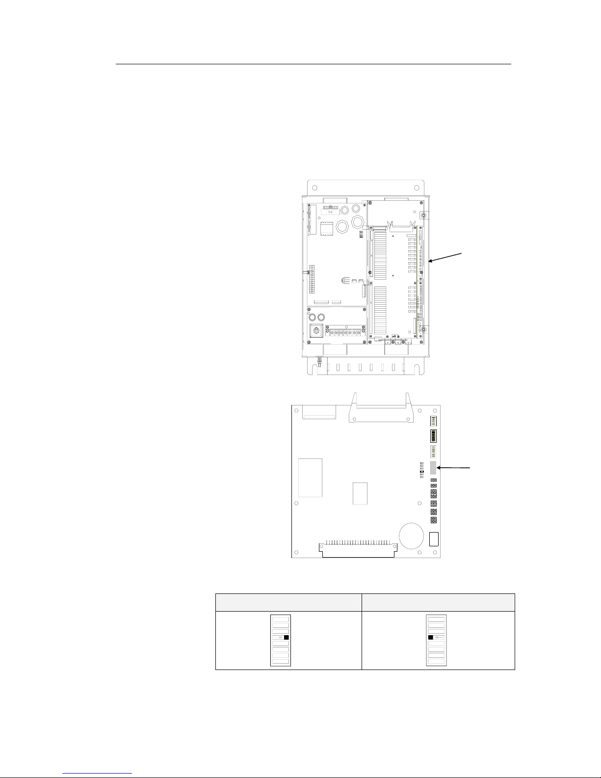
Configuring the Control unit
When the gyro system is shipped from factory, all dip switches
in the Control unit are set as for a standard GC80 system.
Before the system is started, dip switch no.2 on S1 on the SCC
board has to be changed to identify the system as a GC85
system.
The SCC board is located underneath the GTERM board.
J1
J4
J3
J2
6
1ON
8
1ON
SW4
8
1ON
SW3
SW2
SW1
ON81
DS1
DS2
DS3
DS4
DS5
DS6
12
12
12
56
12
34
132
4
132
4
J5
J6
J7
J8
J9
J10
U1
U52
BT1
SCC board
GC80 system GC85 system
OFF
S1
1
8
S1
8
1
ON
SCC
BOARD
SW1
Page 50
Simrad GC80/GC85 Expanded Gyro Compass
42 20221529 / C
External heading sensor
If an external heading sensor is connected to the GC80/GC85,
dip switch no.5 on S1 on the SCC board has to be set to activate
the external heading sensor.
J1
J4
J3
J2
6
1ON
8
1ON
SW4
8
1ON
SW3
SW2
SW1
ON81
DS1
DS2
DS3
DS4
DS5
DS6
12
12
12
56
12
34
132
4
132
4
J5
J6
J7
J8
J9
J10
U1
U52
BT1
SCC board
No external sensor Active external sensor
OFF
8
1
S1
ON
S1
1
8
SCC
BOARD
SW1
Page 51

INSTALLATION
20221529 / C 43
Pendulum function
If an external switch is connected to GC80/85 to operate the
pendulum function, dip switch no.4 on S2 on the SSC board has
to be set to activate the pendulum function.
SCC board
U52
J3
U1
J1
21
BT1
J2
J10
4
J9
J8
2
2
4
4
3
1
1
3
3
DS2
DS6
DS5
DS4
DS3
DS1
SW1
J6
J7
2
6
2
J5
ON
2
1
5
1
1
1
SW2
SW3
ON
ON
8
1
8
1
8
J4
SW4
ON 1
6
Pendulum function disabled Pendulum switch enabled
OFF
S2
1
8
ON
S2
8
1
SCC
BOARD
SW2
Page 52

Simrad GC80/GC85 Expanded Gyro Compass
44 20221529 / C
5.6 Installing the Sensitive element
The Sensitive element is shipped from the factory packed
separately, and the element has to be installed in the Master
compass according to the description below.
Note! A special tool (Simrad part no. 44174449) is required when
installing the Sensitive element. This tool is delivered together
with the gyro, and the sensitive element should not be installed
without using this tool.
Caution Use extreme caution when handling the Sensitive element! Do
not tilt the element. It is filled with oil and the top is open.
1 Make sure that the master compass is installed and cables
connect according to the description on page 37 onwards.
2 Remove the four screws on the Horizontal ring.
3 Lift the sensitive element carefully from its package, and
remove the rubber tube on top of the element.
Note! The package and the rubber tube should be kept for re-use if the
Sensitive element has to be sent to factory for service!
4 Tilt the Horizontal ring to the side where the plug is
located, and carefully put the sensitive element into the
ring.
- The socket on the Sensitive element should be located
right above the plug attached to the Horizontal ring.
5 Position the Sensitive element on the Horizontal ring by
putting the assembly jigs into the holes as indicated on the
figure below. Observe the labelling and the diameter on
the jigs. Fasten two screws in the other two holes.
Page 53

INSTALLATION
20221529 / C 45
6 Replace the assembly jigs with the two remaining screws.
Locate the ground wire on one of the screws as shown on
the figure.
7 Loosen the screw on the plug-holder on the Sensitive
element, and lift the holder 2-3 mm upwards.
8 Connect the plug to the connectors on the Sensitive
element’s pcb according to the labelling on the pcb and on
the wires. Make sure that the pin guides on the plug are
properly entered, and that the wires not are twisted.
9 Firmly tighten the screw on the holder.
ASSEMBLY JIG
WITH 1 CIRCLE
ASSEMBLY JIG
WITH 2 CIRCLES
Page 54

Simrad GC80/GC85 Expanded Gyro Compass
46 20221529 / C
Verifying the element’s tilt angle
1 Tilt the Sensitive element by hand towards the level tool
on the Horizontal ring and keep it tilted for approximately
1 minute. Remove the pressure and observe that the tilt
angle remains at:
- GC80: 15° to 19°
- GC85: 18° to 22°
The tilt angle is indicated on the figures below.
1
5
°
1
9
°
Max and min tilt angle for GC80 std system
1
8
°
2
2
°
Max and min tilt angle for GC85 High Speed system
Note! The tilt angle shown above is correct for cold condition. The
angle may change when the element has reached normal
operational temperature!
Page 55

INSTALLATION
20221529 / C 47
2 If the tilt angle is incorrect, weight disks must be adjusted
by moving weights from one side to the other. After
adjustments, wait for 2 minutes before the tilt angle
verification is repeated.
Caution The sensitive element must have equal number of weight disks
on both weight points on the tilting side (north and south
side)!
3 Carefully rotate the Horizontal ring at least one complete
rotation. Verify that all movable parts will rotate without
making any contact with mechanical or electrical
components.
4 Lift the lid from the damper oil case, and fill the container
with the supplied damper oil. The oil has high viscosity,
and care should be taken when pouring the damper oil into
the container to avoid spill. Reinstall the lid on the damper
oil case.
Any oil spilled on the outside should be wiped up.
Page 56

Simrad GC80/GC85 Expanded Gyro Compass
48 20221529 / C
5.7 System start-up and software configuration
When all GC80 units are installed and the cables connected
according to the procedures described in previous chapters, the
system is ready for the first time start-up procedure.
System Start-up
mltbo
1 Turn ON the gyro system by pressing the POWER button
on the Control panel. The following start-up sequence will
be run:
- Control unit type (GC80 Std, or GC80 HSc), SW version
for Control unit and for Master compass is displayed in
rapid succession. Examples of display text are shown
below:
OR
GC80 CONTROL
UNIT
STD VERSION
GC80 CONTROL
UNIT
HIGH SPEED
VERSION
SW VERSION
CONTROL UNIT
SW. VERSION
MASTER COMPASS
dvol
2 The sensitive element starts rising horizontally, and the
compass rotates 360° clockwise. The display shows
decreasing bearing as the compass is rotating.
3 If the gyro has been turned ON and OFF again, but rotor
still rotation when the
POWER button was pressed for new
start, a rotor break function will be activated to stop the
rotor completely.
- Active rotor break is indicated with flashing display.
dvol
4 When the rotation is stopped, start bearing is indicated
with flashing text in the display. The start bearing will be
the same as active bearing when the compass was turned
OFF.
Page 57
INSTALLATION
20221529 / C 49
dvol
5 The indicated start bearing is accepted by pressing the
ACK/ENT button, or increased/decreased by using the
arrow buttons and then pressing the ACK/ENT button. If
no action is taken within 3 minutes, the start-up process
will continue with the indicated start bearing.
The bearing indication stops flashing when the start
bearing is accepted, while the lamp remains flashing.
The rotor starts rotating, and reaches pre-described number
of revolutions after maximum 30 minutes.
dvol
6 When the rotor has reached full speed, the compass starts
the north seeking rotation. The display will now change to
show the compass’ actual heading, and from now on
bearing output will be available.
The lamp beside the GYRO button change from flashing to
steady light.
The GC80/GC85 will be settled within 3 hours when started
with a deviation angle less than 5°. With a larger deviation
angle, the compass will be settled within 4 hours.
Configuring the gyro system
Each Sensitive element is tuned to its Master compass before it
is shipped from the factory. This tuning is reflected in a set of
parameters specific for this gyro compass. These parameters are
included in the sensitive element’s package, and they have to be
entered into the Control unit as part of the gyro compass’
installation procedure.
The parameters are loaded into the Control unit from the
Extension menu as described below.
1 Enter the Extension menu by pressing and holding the SET
button and the ACK/ENT buttons simultaneously for at
least 3 seconds.
Main category A-1 will be displayed.
2 Press the SET button to enter the sub-category loop. Sub-
category 1.1.U and its parameter values will be displayed.
3 Use the arrow buttons to increase or decrease the
parameter value until the value is according to the labelling
for the sensitive element.
4 Confirm the entry by pressing the ACK/ENT button. The
display will return to sub-category 1.1.U, and the data will
be transferred to the gyro immediately.
Page 58

Simrad GC80/GC85 Expanded Gyro Compass
50 20221529 / C
5 Press the DISP button again to select sub-category 1.2.F,
and use the arrow buttons to increase or decrease the
parameter value until the value corresponds with the
parameter for the new sensitive element. Confirm the entry
by pressing the ACK/ENT button.
6 Repeat step 5 for sub-category 1.3.S, 1.4.u, 1.5.L and
1.6.t.
7 Press the SET button again to return to main category A1,
and then press the DISP button to go to A2 main category.
8 Press the
SET button, and enter values for 2.1.o and 2.3.h
as described above.
While still in A2 main category, enter values for 2.5.y (Year),
2.6.N (Month and Day), 2.7.t (Hour and Minute) and 2.8.d (total
days of operation. This value should be reset after installation).
Note! All time parameters should be in CET (Central European Time)
or local time.
9 Press the SET button again to return to main category A2,
and then press the DISP button until main category A7 is
displayed.
10 Press the
SET button, and enter the value for 7.3.u as
described above.
11 Exit the sub-category by pressing the
SET button, and then
exit the Extension main category by pressing and holding
the SET and ACK/ENT buttons simultaneously for at least
3 seconds.
For more information about the Extension menu, see
ADVANCED SETTINGS, page 55 onwards.
Page 59

INSTALLATION
20221529 / C 51
Setting the Latitude input system
The latitude input system may be changed during the settling
process of the start-up procedure from item 7 onwards.
1 Press the DISP button until the display shows latitude
value.
2 Press SET button once, and the upper line in the display
starts flashing.
3 Use the arrow buttons for selecting Gyro or GPS as the
latitude input system, and confirm the entry with the
ACK/ENT button.
4 The display will change to flashing number.
5 Press the arrow buttons for increasing/decreasing the
latitude value, and confirm the entry with the ACK/ENT
button.
- This entered latitude value will now be used, together
with speed and bearing information, for calculating the
vessel’s current latitude.
6 The display will return to show latitude value without
flashing.
Page 60
Simrad GC80/GC85 Expanded Gyro Compass
52 20221529 / C
Setting the Speed input system
The latitude input system may be changed during the settling
process of the start-up procedure from item 7 onwards.
1 Press the DISP button until the display shows speed value
and speed input system.
2 Press SET button once, and the upper line in the display
starts flashing.
3 Use the arrow buttons for toggling between available
speed input systems:
Manual
GPS
LOG (pulse)
LOG (serial)
4 Select active speed input system, and confirm the selection
by pressing the
ACK/ENT button.
5 If Manual input system is selected, the display will change
to show flashing numerical values.
6 Use the arrow buttons for entering the speed value, and
confirm the input by the ACK/ENT button.
7 The display will return to shown speed value and speed
input system without flashing.
Page 61
INSTALLATION
20221529 / C 53
5.8 Balancing the Horizontal ring
After the compass has been running continuously for at least 2
hours, the horizontal ring should be adjusted.
1 Locate the reference level tool on the horizontal ring, and
check that the level bubble is within +/-10 minutes from
the center. Each division equals 2 minutes.
2 If the level bubble not is within this limit, add or remove
weights from the horizontal ring until it is levelled.
Note! It is important that the total number of weights on the horizontal
ring are as few as possible.
3 Let the compass run for at least 20 minutes before the
level is rechecked and eventually confirmed.
Caution If the horizontal ring is tilted more than +/-10’, a bearing error
will be generated.
Adjusting True heading
After the GC80/85 is settled, the gyrocompass has to be
calibrated against an external reference, e.g.:
- a known target
- astronomical observation
- the heading of the pier or quay the vessel is moored to
- two fixed points on the chart that the vessel is sailing
between
The observation period for the heading difference should be as
long as possible.
If there is any difference between the gyro bearing and the
confirmed external reference that not can be corrected by
adjusting the mechanical location of the master compass, an
offset value may be inserted in the GC80. This value is entered
by using the Extension menu as follows:
1 Activate the Extension menu by pressing and holding the
SET button and the ACK/ENT buttons simultaneously for
at least 3 seconds.
- Main category A-1 will be displayed.
10 minutes
Page 62

Simrad GC80/GC85 Expanded Gyro Compass
54 20221529 / C
2 Press the DISP button once to display main category A-2.
3 Press the SET button to enter the sub-category 2.1.o.
4 Use the arrow buttons to increase or decrease the offset
parameter value.
Note! To correct for +1.5°, press the Arrow Up button until the
display shows 1.5°.
To correct for -1.5°, press the Arrow Down button until the
display shows 358.5°!
5 Confirm the new value by pressing the ACK/ENT button,
or reject the changes by pressing the SET button. The
display will return to sub-category 2.1.o.
6 Exit the Extension menu by pressing and holding the
SET
and
ACK/ENT buttons simultaneously for at least 3
seconds.
For further information about the Extension menu, refer Using
the Extension menu, page 56 onwards.
Page 63

ADVANCED SETTINGS
20221529 / C 55
6 ADVANCED SETTINGS
This section gives an overview of the Extension menu, how
to enter the menu and how to change parameter values.
Page 64

Simrad GC80/GC85 Expanded Gyro Compass
56 20221529 / C
6.1 General
The Extension menu holds internal parameters and
communication parameters required to achieve the best possible
heading accuracy on the GC80/GC85 Gyro compass.
The Extension menu is grouped in 8 main categories, named A1 through A-8. Each of these main categories has again several
sub-categories where parameter values may be set.
All values in the Extension menu are stored in the nonvolatile
memory of the compass.
6.2 Using the Extension menu
Caution The Extension menu should not be entered by unauthorized
personnel. Incorrect parameters may result in irregular
operation of the GC80/GC85 gyro compass!
The extension menu can be entered when any display is shown
in the LCD.
1 Activate the menu by pressing and holding the SET button
and the ACK/ENT buttons simultaneously for at least 3
seconds.
- Main category A-1 will be displayed.
2 Page through the main categories to the selected category
by pressing the DISP button. Pressing the DISP and
ACK/ENT buttons simultaneously will display the main
category loop in reversed order.
3 Press the SET button to enter the sub-category loop, and
use the DISP button to select sub-category that holds the
parameter to be changed.
4 Use the arrow buttons to increase or decrease the
parameter value.
5 Confirm the new value by pressing the ACK/ENT button,
or reject the changes by pressing the SET button. The
display will return to selected sub-category.
6 Exit the Extension menu by pressing and holding the SET
and ACK/ENT buttons simultaneously for at least 3
seconds.
Page 65

ADVANCED SETTINGS
20221529 / C 57
afpm
afpm
^`h
bkq
pbqpbq
^`h
bkq
afpm
afpm
^`h
bkq
pbq
^`h
bkq
6.3 The Extension menu overview
Main
Category
Sub
Category
Parameter/description
Default
value
Range
A-1
1.1.U Damping gain
Determines the damping (damping operation in northseeking motion = half cycle attenuation) and actually
represents a coefficient (ratio) to the standard value
stored in the software.
1.00 0.00 – 2.00
1.2.F Bearing servo gain
Determines the gain of the bearing servo loop where phi
Φ signal (deviation signal around rotor’s vertical axis)
is calculated, drives the azimuth step motor and has the
sensitive element follow to the gyro-sphere vertical axis
(around azimuth axis) rotation. Presents a coefficient
(ratio) to the standard value stored in software.
1.00 0.00 – 2.00
1.3.S Horizontal servo gain
Determines the gain of the horizontal servo loop where
theta θ signal (rotor tilting angle signal) is calculated,
drives the horizontal DST and has the sensitive element
follow to the gyro sphere tilting angle (rotor tilting
angle). Present a coefficient (ration) to the standard
value stored in software.
1.00 0.00 – 2.00
1.4.u Leveling servo gain
Leveling motion (sensitive element erection motion)
calculates X signal (equivalent inclination angle) which
is output from the sensitive element and relative
inclination angle signal from HRZC board, controls to
have the sensitive element keep horizontal. The value
determines this control loop gain. Presents a coefficient
(ratio) to the standard value stored in the software.
1.00 0.00 – 2.00
CHANGE /
CLEAR
PARAMETER
VALUE
NEXT MAIN
CATEGORY
NEXT SUB
CATEGORY
MAIN
MENU
Page 66

Simrad GC80/GC85 Expanded Gyro Compass
58 20221529 / C
Main
Category
Sub
Category
Parameter/description
Default
value
Range
A-1 cont.
1.5.L (φ) Phi offset (°)
Offset value (°) around the vertical axis of gyro sphere
(rotor axis) and the sensitive element.
0.00 -3.00 – 3.00
1.6.t (θ) Theta offset (°)
Offset value (°) around the horizontal axis of gyro
sphere (rotor axis) and the sensitive element.
0.00 -3.00 – 3.00
1.7.G X signal pickup gain (v/°)
Distance of the sensitive element share and the rotor
axis direction. Inclination angle around horizontal axis
is obtained equivalently by monitoring this signal. For
example, when north side of the rotor axis rises, the
sensitive element follows to rise its north side, then
gyro sphere suspended by the suspension wire moves to
south side. X signal represents this amount of
movement (v/°).
This parameter is only used for GC85.
2.32 0.00 – 5.00
1.8.c Ks/H
Suspension wire twist torque. Fixed value.
1.477 1.000 – 2.000
1.9.r Maximum rate of turn (°/sec)
Maximum rate of turn in the turn rates which the
b
earing servo system followed up to this moment
(°/sec).
NOTE:
The maximum is measured after 3 hours from
system start.
NOTE:
Reset this data certainly after completion of
installation!
0.00 -
1.A.F Maximum deviation of bearing servo (°)
Maximum deviation value in the bearing servo loop that
occurred up to this moment (°).
NOTE:
The maximum is measured after 3 hours from
system start.
NOTE:
Reset this data certainly after completion of
installation!
0.00 -
1.b.S Maximum deviation of horizontal servo (°)
Maximum deviation value in the horizontal servo loop
that occurred up to this moment (°).
NOTE:
The maximum is measured after 3 hours from
system start.
NOTE:
Reset this data certainly after completion of
installation!
0.00 -
Page 67

ADVANCED SETTINGS
20221529 / C 59
Main
Category
Sub
Category
Parameter/description
Default
value
Range
A-2
2.1.o Bearing offset A (°)
Offset value included in the “master bearing” and used
for correction of fixed error (°). If the master compass
not can be mounted parallel to the vessel’s fore-after
line, this parameter is used to compensate for a small
mounting error.
0.0 0.0 – 359.9
2.2.O Bearing offset B (°)
Value for general bearing error correction to enter to
master compass bearing. It is used to correct the bearing
if the bearing for some reason deviates from correct
heading.
This value is cleared when it passes the zero-cross pin
or when power is switched OFF.
0.0 0.0 – 359.9
2.3.h Zero-cross bearing (°)
Absolute bearing set for MCU board when zero-cross
pin was passed during start-up sequence (last azimuth
operation) and normal running operation.
Zero-cross bearing can be set in this menu, but is
normally set up be measuring position (angle) of the
zero-cross pin in the master com
p
ass by the test mode
A.
345.3 0.0 – 359.9
2.4.E Zero-cross error allowance (°)
Zero-cross alarm limit. The compass will generate a
zero cross alarm when the difference between the zerocross bearing and the relative bearing exceeds this zero
cross value.
This value should be set every time the zero-cross pin is
detected.
2.0 0.0 – 5.0
2.5.y Year
Used for setting current year.
- 2000 - 2099
2.6.N Month and Day
Used for setting current month and date.
- -
2.7.t Hour and Minute
Used for setting current hour and minute.
- -
2.8.d Total days of operation
This value should be reset after the installation is
completed.
- -
Page 68

Simrad GC80/GC85 Expanded Gyro Compass
60 20221529 / C
Main
Category
Sub
Category
Parameter/description
Default
value
Range
A-2 cont.
2.9.G Display/setting of GPS connection
The following abbreviations are used:
bE: GPS connected
Non: No GPS connected
NOTE
: When this value is set to “Non”, GPS can not
be selected as the vessel’s input for speed and
latitude.
- bE or Non
2.A.L Display/setting of LOG connection
The following abbreviations are used:
bE: with Log (contact)
Non: No Log (contact)
NOTE
: When this value is set to “Non”, LOG can not
be selected as the vessel’s speed input.
- bE or Non
2.b.S Display/setting of LOG (serial) connection
The following abbreviations are used:
bE: with Log (serial)
Non: No Log (serial)
NOTE
: When this value is set to “Non”, SLOG can not
be selected as the vessel’s speed input.
- bE or Non
2.c.t Display/setting of GPS performance index data check
The following abbreviations are used:
bE: Check performance index
Non: Not check performance index
- bE or Non
2.d.o Analogue signal output offset for ROT (°)
Offset value for analogue signal output of Rate Of
Turn. Entered value is +/-5% of maximum output ROT.
0.00 0.0 – 16
1
2.e.F Filter time constant for rate of turn (sec) 2.00 0.5 – 10.0
2.F.G Analog output gain for rate of turn 1.00 0.90 – 1.00
3.1.E Alarm (error) - -
3.2.n Occurred number of zero-cross error - -
3.3.H Maximum zero-cross error - -
3.4.y Occurred year of zero-cross error - -
3.5.N Occurred month/day of zero-cross error - -
3.6.t Occurred hour/minute of zero-cross error - -
3.7.n Occurred number of encoder error - -
A-3
3.8.r Occurred number of reset with WATCH DOC TIMER - -
1
The maximum value is 5% of the maximum analog output for rate of turn.(32 deg./min: 1.6deg./min.,
130deg./min: 6.5deg./min., 320deg./min: 16.0deg./min.)
Page 69

ADVANCED SETTINGS
20221529 / C 61
Main
Category
Sub
Category
Parameter/description
Default
value
Range
A-4
4.1.C GPS serial data character length 8 8 or 7
4.2.P GPS serial data parity bit Non Non, Even,
Odd
4.3.S GPS serial data stop bits 1 1 or 2
A-5
5.1.C LOG serial data character length 8 8 or 7
5.2.P LOG serial data parity bit Non Non, Even,
Odd
5.3.S LOG serial data stop bits 1 1 or 2
A-6
6.1.C External sensor (standard) serial data character length 8 8 or 7
6.2.P External sensor (standard) serial data parity bit Non Non, Even,
Odd
6.3.S External sensor (standard) serial data stop bits 1 1 or 2
A-7
7.1.t Master compass type Std Std or Hsc
7.2.u SCC software version number - -
7.3.u MCC software version number - -
A-8
8.1.t For confirmation of extension menu - -
8.2.S Filter of speed error correction On On or Off
Page 70

Simrad GC80/GC85 Expanded Gyro Compass
62 20221529 / C
THIS PAGE INTENTIONALLY LEFT
BLANK
Page 71

TECHNICAL SPECIFICATION
20221529 / C 63
7 TECHNICAL SPECIFICATION
This section list all specifications for GC80/85 gyro
compass.
Page 72

Simrad GC80/GC85 Expanded Gyro Compass
64 20221529 / C
7.1 Accuracy
Settling time:.......................................................... within 3 hours
(if startup heading is within +/-5° of actual heading)
Settle point error: ................................................... less than ±0.1º
RMS value of the difference:................................... less than 0.1º
Repeatability of settle point error: ......................... less than ±0.1°
Roll and pitch error:...............................................less than ±0.4°
Static error: ............................................................less than ±0.1°
Settle point error under general conditions:........... less than ±0.4°
Note! Accuracy at equator. For other latitudes, accuracy to be
multiplied by *(1/COS f), where f = Latitude.
7.2 General specification
Follow-up speed..............................................................> 75°/sec
Gimbal freedom ................................for both roll and pitch: ±45°
Range of speed correction:
GC80 ................... 0-50 knots / latitude (0° - +70°)
GC85 ................... 0-70 knots / latitude (0° - +70°)
Main power supply: .................. 100/110/115/200V AC, 50/60Hz
Power supply for alarm and back-up:.................... 24V DC, 70W
Voltage fluctuation: .......................................................AC ±10%
DC -20% - +30%
Frequency variation: .............................................................. ±5%
Power consumption:
Start:.....................................................within 140VA
Ordinary:................................................within 70VA
Repeater: ................................................within 17VA
Repeater type: .................................................. 24V DC – 6 step/°
Number of step repeater connections: .........................................4
Number of NMEA connections:................................................10
Repeater back-up circuits: .................................................... 4+10
Pendulum function....................................................refer page 18
Page 73

TECHNICAL SPECIFICATION
20221529 / C 65
7.3 Input specification
Serial input signal (GPS)
Circuits:.....................................................................1
Electrical: .............. RS422/MNEA0183/Current loop
Baud rate:..................................................... 4800 bps
Data bits: ............................................................ 8 bits
Parity:.................................................................None
Stop bits: ...................................................................1
Transmit freq.: ...............................................1 – 5Hz
Input format:
$--GGA,x,xxxx.xx,N,xx.x,E,x,~*hh<CR><LF>
$--GLL,xxxx.xx
,N,xxxx.xx,E,*hh<CR><LF>
$--VTG,xx
,T,xx,M,xx.x,N,xx,K*hh<CR><LF>
Serial input signal (External heading)
Circuits:.....................................................................1
Electrical: .................................... RS422/NMEA0183
Baud rate:.......................................... 4800/38400 bps
Data bits: ............................................................ 8 bits
Parity:.................................................................None
Stop bits: ...................................................................1
Transmit freq.: ............................1 - 50Hz/20 – 50Hz
Input format:
$--HDT,xxx.x*hh<CR><LF>
$--HDG,xxx.x
*hh<CR><LF>
Serial input signal (LOG)
Circuits:.....................................................................1
Electrical: .................................... RS422/NMEA0183
Baud rate:..................................................... 4800 bps
Data bits: ............................................................ 8 bits
Parity:.................................................................None
Stop bits: ...................................................................1
Transmit freq.: ..............................................1 - 50Hz
Input format:
$--VBW,x.x,x.x,A,~*hh<CR><LF>
PULSE signal (LOG)
Circuits:.....................................................................1
Electrical: .................... 200/400 p.p.n.m., dry contact
Page 74

Simrad GC80/GC85 Expanded Gyro Compass
66 20221529 / C
7.4 Output specification
Serial output signal 1
Circuits:...................................................................10
Electrical: ..................................................RS422/485
Baud rate:
GC80: ...................................................... 4800 bps
GC85 ..................................................... 38400 bps
Note! Baud Rate for GC85, refer Jumper settings on SIFC board,
output serial signal selection, page 95.
Data bits: ............................................................ 8 bits
Parity:.................................................................None
Stop bits: ...................................................................1
Transmit freq.:
GC80 ............................................................. 10Hz
GC85: ............................................................50Hz
Output format:
Data no.1
$ HEHDT,xxx.x,T*hh<CR><LF>
Data no.2
$ HEROT,-xxx.xx,A*hh<CR><LF>
Data no.3
$ PCICM,HEALM,xxxx,x,xx*hh<CR><LF>
Serial output signal 2 *1
Circuits:...................................................................10
Electrical: ..................................................RS422/485
Baud rate:
GC80: ...................................................... 4800 bps
GC85 ..................................................... 38400 bps
Data bits: ............................................................ 8 bits
Parity:.................................................................None
Stop bits: ...................................................................1
Transmit freq.:
GC80 ............................................................. 10Hz
GC85: ............................................................50Hz
Output format:
Data no.1
$ HEHDT,xxx.x,T*hh<CR><LF>
Data no.2
$ PTICM,--xxxx,x,xx,*hh<CR><LF>
When Gyro
is selected
When
External
heading
sensor is
selected
Page 75

TECHNICAL SPECIFICATION
20221529 / C 67
STEP signal
Circuits:.....................................................................4
Electrical: ...................................... 24V DC – 6 step/°
RATE OF TURN signal
Circuits......................................................................1
Electrical: ........................ +/-10V (+/-120°) (default),
+/-10V (+/-30°),
+/-10V (+/-300°),
+/-5V (+/-120°),
+/-5V (+/-300°),
+/-5V (+/-30°)
Note! Refer Rate of Turn scale dip switch settings, page 92, and to the
separate manual delivered for Rate of Turn Instrument.
Alarm output
Potential free .................................................. NO/NC
Running contact
Potential free .................................................. NO/NC
Refer Jumper settings on SCC board, page 93.
7.5 Physical Dimensions
GC80/GC85 Master Compass
Height: .................................................................438 mm (17.2”)
Width: .................................................................. 340 mm (13.4”)
Depth: ..................................................................340 mm (13.4”)
Weight: .................................................................... 23 kg (51lbs)
GC80 Expanded Control Unit
Height: .................................................................495 mm (19.5”)
Width: .................................................................. 364 mm (14.3”)
Depth: ....................................................................182 mm (7.2”)
Weight...................................................................... 14kg (31 lbs)
Page 76

Simrad GC80/GC85 Expanded Gyro Compass
68 20221529 / C
7.6 Power
GC80/GC85 Master Compass
Voltage input: .................................... Supplied from Control unit
GC80 Expanded Control Unit
Voltage input: .........................................................110/220V AC
Backup voltage: ............................................................... 24V DC
Power consumption, including Master compass:
Starting........................................... 1.5A at 100V AC
Running:......................................... 1.2A at 100V AC
7.7 Environmental Specification
GC80/GC85 Master Compass
Enclosure material: ...................................................... Aluminum
Color: ................................................................................... Black
Temperature range:
Operating: .............................-10 - 50°C (14 - 122°F)
Storage: .............................. -25 – 70°C (-13 – 158°F)
Angular freedom of gimbal: ......................±45° for roll and pitch
GC80 Expanded Control unit
Enclosure material: ...................................................... Aluminum
Environmental protection: ..................................................... IP22
Color: ................................................................................... Black
Temperature range:
Operating: .............................-10 - 50°C (14 - 122°F)
Storage: .............................. -25 – 70°C (-13 – 158°F)
Page 77

DRAWINGS
20221529 / C 69
8 DRAWINGS
This section contains outline drawings showing mechanical
dimensions of the different GC80/GC85 units, together
with wiring diagrams for the gyro system.
Page 78

Simrad GC80/GC85 Expanded Gyro Compass
70 20221529 / C
8.1 Drawings included
The following mechanical drawings are enclosed:
Name Drw. no Rev.
GC80 Expanded Control unit, dimensions N3-710186 A
GC80/85 Master Compass, dimensions N3-710179 A
GC80/85 Remote panel, dimensions D4-710208 B
To scale drawings are available upon request.
The following wiring diagrams are enclosed:
Name Drw. no Rev.
GC80/85 Gyro Compass, Expanded system.
Wiring diagram (page 1 and 2)
N4/N3-710185 C
Note! The original signed drawings are recorded at Simrad Egersund.
Page 79

DRAWINGS
20221529 / C 71
pбгк~З=bЦЙклмеЗ=^p
klot^v
J
bdboprka
d`UMLd`UR
aбгЙелбзел
bсй~еЗЙЗ=`зенкзд=мебн
N
Pk
N
TNMNUS
^
Page 80

Simrad GC80/GC85 Expanded Gyro Compass
72 20221529 / C
_lt
pбгк~З=bЦЙклмеЗ=^p
klot^v
J
bdboprka
d`UMLd`UR
aбгЙелбзел
j~ëíÉê=`çãé~ëë
N
Pk
N
TNMNTV
^
^ob^
pbosf`b
^ob^
pbosf`b
^ob^
pbosf`b
^ob^
pbosf`b
_lt
Page 81

DRAWINGS
20221529 / C 73
Page 82

Simrad GC80/GC85 Expanded Gyro Compass
74 20221529 / C
37
38
39
40
41
42
43
44
45
TB1
GRX+
GRXGSC
LRX+
LRX-
LSC
ESRX+
ESRX-
ESC
SL+ 46
SL-
GPS SIGNAL INPUT
$--VTG
$--GGA
$--GLL
MNEA
$--VBW
BELOW
IEC61162-1/-1.Ed2
CURRENT LOOP
SPEED LOG SIGNAL INPUT
200/400 pulse/n.mile
47
TB1
MASTER COMPASS
GC80/85
1
2
1
2
3
9
10
11
12
13
TB2
N+
NAL1
AL2
ALC
EA+
EA-
EB+
EB-
ECC
4
5
6
7
8
14
MT+
MT-
MR+
MR-
MSC
FGND
EMERGENCY SOURCE (DC24V)
220/110V AC (50-60Hz)
1
2
3
4
5
11
12
13
14
15
TB1
N+
NAL1
AL2
ALC
EA+
EA-
EB+
EB-
ECC
6
7
8
9
10
16
MT+
MT-
MR+
MR-
MSC
FG
GC80 EXPANDED
CONTROL UNIT
AC1
AC2
B+
B-
TB101
pбгк~З=bЦЙклмеЗ=^p
klot^v
J
bdboprka
d`UMLUR=dóêç=`çãé~ëë
tбкбеЦ=aб~Цк~г
bсй~еЗЙЗ=pулнЙг
N
Qk
O
TNMNUR
`
RECOMMENDED CABLE TYPES
8
9
7
6
3
5
4
2
1
CABLE NO.
AWG14
CABLE TYPE
(ONE or BOTH)
EXTERNAL HEADING SENSOR
1 2
5
7
8 9
3
4
6
AWG17 SHIELDED
AWG17 SHIELDED
AWG14
AWG18 TWISTED / SHIELDED
AWG18
Shielded cables to be connected to GND
SHIP'S SUPPLY
HDT
AWG14
AWG18 TWISTED / SHIELDED
AWG18 TWISTED / SHIELDED
E+
E-
NOT USED
Page 83

DRAWINGS
20221529 / C 75
ALCN2
RNCN2
EACK+
RNCN1
BZSP+
BZSP-
EACK-
50
707172
686967
575865
66
535449
TB1
pбгк~З=bЦЙклмеЗ=^p
klot^v
J
bdboprka
d`UMLUR=dóêç=`çãé~ëë
tбкбеЦ=aб~Цк~г
bсй~еЗЙЗ=pулнЙг
O
Pk
O
TNMNUR
`
ANALOG RATE OF TURN
ALARM RELAY
READY CONTACT
REMOTE ALARM ACKNOWLEDGE
REMOTE BUZZER STOP
GYRO SELECT SW
EXTERNAL SELECT SWITCH
32303128292627
24
25
RECOMMENDED CABLE TYPES
CABLE NO. CABLE TYPE
23
221921
20
18
171416
15
131211
10
10 11 12 13
16
14 15 17
19
18
20
21
22
23 24 25 26 27 28 29
30 31 32
Shielded cables to be connected to GND
AWG17 SHIELDED
AWG17 SHIELDED
AWG17 SHIELDED
AWG17 SHIELDED
AWG18 TWISTED / SHIELDED
AWG18 TWISTED / SHIELDED
CONTROL UNIT
GC80 EXPANDED
TB2
23
24
ST44
45
ST4246
ST4347
ST1157
ST1258
ST1359
ST1460
ST45
ST41
ST1561
626364656667686970
71
ST21
ST22
ST23
ST24
ST25
ST31
ST32
ST33
ST34
ST35
12345
1112131415
TB2
1TX+
1TX-
1TSC
1R24-
1R24+
678
9
10
1617181920
255TX+26272829
5TSC
5TX-
2TX+
2TX-
2TSC
2R24-
2R24+
3TX+
3TX-
3TSC
3R24-
3R24+
4TX+
4TX-
4TSC
4R24-
4R24+
5R24-
5R24+
8R24+
8R24-
8TSC
8TX-
8TX+
444342414039383736
35
7R24+
7R24-
7TSC
343332
7TX-
7TX+
31
30
6R24+
6R24-
6TSC
6TX-
6TX+
36
35
10R24+
10R24-
10TSC 34
33
32
10TX-
10TX+
31
30
9R24+
9R24-
9TSC 29
28
27
9TX-
9TX+
TB1
GCC+61
ECC+
ECC-
GCC-
636462
1RT+
2RT+
2RT-
3RT+
1RT-
3RT-
ALCN1
AWG18 TWISTED / SHIELDED
AWG18 TWISTED / SHIELDED
AWG18 TWISTED / SHIELDED
AWG18 TWISTED / SHIELDED
NMEA OUT:
HEHDT & HEROT
DC24V
STEP SIGNAL
STEP MOTOR
REPEATER MOTOR CONNECTION METHOD
TERMINAL BOARD
ST X2
ST X3
ST X4
ST X5
ST X1
STEP 1
STEP 2
STEP 3
24V RETURN
+ 24V DC
AWG18
AWG18
AWG18
AWG18
AWG20
AWG20
AWG20
AWG20
AWG20
AWG18 TWISTED / SHIELDED
AWG18 TWISTED / SHIELDED
AWG18 TWISTED / SHIELDED
AWG18 TWISTED / SHIELDED
PENDULUM /
Page 84

Simrad GC80/GC85 Expanded Gyro Compass
76 20221529 / C
THIS PAGE INTENTIONALLY LEFT
BLANK
Page 85

SPARE PART LIST
20221529 / C 77
9 SPARE PART LIST
This section includes part numbers for all standard and
optional units that may be included in a GC80 and GC85
gyro system.
Page 86

Simrad GC80/GC85 Expanded Gyro Compass
78 20221529 / C
9.1 GC80 Expanded Gyro system
PART NO DESCRIPTION
27101674
GC80 Master compass
44174027
GC80 Sensitive element
27101708
GC80 Expanded Control unit
20221529 GC80/GC85 Expanded gyro compass Instruction manual
44174449 Special tool required when installing the Sensitive element
9.2 GC85 Expanded Gyro system
PART NO DESCRIPTION
27101682
GC85 Master compass
44170728
GC85 Sensitive element
27101708
GC80 Expanded Control unit
20221529 GC80/GC85 Expanded gyro compass Instruction manual
44174449 Special tool required when installing the Sensitive element
Page 87

SPARE PART LIST
20221529 / C 79
9.3 Optional equipment, GC80/85 Expanded
system
PART NO DESCRIPTION
27101757
GC80 Flush mounting kit in Simrad design for remote
installation of operating panel
44170736
GC80 Extension cable 5 meter for remote installation of
operating panel normally mounted in Control unit
44170744
GC80 Extension cable 10 meter for remote installation of
operating panel normally mounted in Control unit
44170751
GC80 Extension cable 15 meter for remote installation of
operating panel normally mounted in Control unit
Page 88

Simrad GC80/GC85 Expanded Gyro Compass
80 20221529 / C
THIS PAGE INTENTIONALLY LEFT
BLANK
Page 89

TERMINAL LAYOUT
20221529 / C 81
10 TERMINAL LAYOUT
This section includes tables which list all terminal pins and
terminal labelling on GTERM board in the GC80
Expanded Control unit. The tables include detailed
description for each terminal.
Page 90

Simrad GC80/GC85 Expanded Gyro Compass
82 20221529 / C
10.1 GTERM board
TB1
PIN NO NAME DETAILS
1 N+ Master compass power supply (24V DC)
2 N- Master compass power supply (24V DC
common)
3 AL1 Master compass inverter alarm (over current)
4 AL2 Master compass inverter alarm (over voltage)
5 ALC Master compass inverter alarm (common)
6 MT+
7 MT-
Control unit – master compass serial signal
8 MR+
9 MR-
Master compass – control unit serial signal
10 MSC Serial signal common
11 EA+ Master compass encoder signal (A phase +)
12 EA- Master compass encoder signal (A phase -)
13 EB+ Master compass encoder signal (B phase +)
14 EB- Master compass encoder signal (B phase -)
15 ECC Master compass encoder signal (common)
16 FGND Earth
17 24R+
18 24R-
19 24B+
20 24B-
Ext. power supply input (no connection)
21 PF
22 POC
23 POV
24 PC
Ext. power supply alarm input (no connection)
25 24M+
26 24M-
Ext. power supply input (no connection)
27 9TX+
28 9TX-
Serial signal output (IEC61162-1 ed.2/-2)
29 9TSC Serial signal common
30 9R24- Serial repeater power supply, -24V DC
31 9R24+ Serial repeater power supply, +24V DC
32 10TX+
33 10TX-
Serial signal output (IEC61162-1 ed.2/-2)
Page 91

TERMINAL LAYOUT
20221529 / C 83
PIN NO NAME DETAILS
34 10TSC Serial signal common
35 10R24- Serial repeater power supply, -24V DC
36 10R24+ Serial repeater power supply, +24V DC
37 GRX+
38 GRX-
GPS serial signal input
39 GSC GPS serial signal common
40 LRX+
41 LRX-
LOG serial signal input
42 LSC LOG serial signal common
43 ESRX+
44 ESRX-
External sensor serial signal input
45 ESC External sensor serial signal common
46 SL+
47 SL-
LOG contact signal input
48 SW+ External power supply switch (Not used)
49 1RT+ Rate of turn analog signal output
50 1RT- Rate of turn signal common
51 1SO+ Rate of turn scale over signal output
52 1SO- Rate of turn signal common
53 2RT+ Rate of turn analog signal output
54 2RT- Rate of turn signal common
55 2SO+ Rate of turn scale over signal output
56 2SO- Rate of turn signal common
57 3RT+ Rate of turn scale over signal output
58 3RT- Rate of turn signal common
59 3SO+ Rate of turn scale over signal output
60 3SO- Rate of turn signal common
61 GCC+
62 GCC-
Sensor select signal input (gyro select)
63 ECC+
64 ECC-
Sensor select signal inut (Ext. sensor select)
65 ALCN1
66 ALCN2
Alarm contact signal output
67 RNCN1
68 RNCN2
Running contact signal output
Page 92

Simrad GC80/GC85 Expanded Gyro Compass
84 20221529 / C
PIN NO NAME DETAILS
69 EACK+
70 EACK-
External acknowledge signal input
71 BZSP+
72 BZSP-
Buzzer stop signal input/Pendulum
TB2
PIN NO NAME DETAILS
1 1TX+
2 1TX-
Serial signal output (IEC61162-1 ed.2/-2)
3 1TSC Serial signal common
4 1R24- Serial repeater power supply, -24V DC
5 1R24+ Serial repeater power supply, +24V DC
6 2TX+
7 2TX-
Serial signal output (IEC61162-1 ed.2/-2)
8 2TSC Serial signal common
9 2R24- Serial repeater power supply, -24V DC
10 2R24+ Serial repeater power supply, +24V DC
11 3TX+
12 3TX-
Serial signal output (IEC61162-1 ed.2/-2)
13 3TSC Serial signal common
14 3R24- Serial repeater power supply, -24V DC
15 3R24+ Serial repeater power supply, +24V DC
16 4TX+
17 4TX-
Serial signal output (IEC61162-1 ed.2/-2)
18 4TSC Serial signal common
19 4R24- Serial repeater power supply, -24V DC
20 4R24+ Serial repeater power supply, +24V DC
21 DFCN1
22 DFCN2
Not used
23 ST44 -24V DC for step signal output 4
24 ST45 +24V DC for step signal output 4
25 5TX+
26 5TX-
Serial signal output (IEC61162-1 ed.2/-2)
27 5TSC Serial signal common
Page 93

TERMINAL LAYOUT
20221529 / C 85
PIN NO NAME DETAILS
28 5R24-
Serial repeater power supply, -24V DC
29 5R24+ Serial repeater power supply, +24V DC
30 6TX+
31 6TX-
Serial signal output (IEC61162-1 ed.2/-2)
32 6TSC Serial signal common
33 6R24- Serial repeater power supply, -24V DC
34 6R24+ Serial repeater power supply, +24V DC
35 7TX+
36 7TX-
Serial signal output (IEC61162-1 ed.2/-2)
37 7TSC Serial signal common
38 7R24- Serial repeater power supply, -24V DC
39 7R24+ Serial repeater power supply, +24V DC
40 8TX+
41 8TX-
Serial signal output (IEC61162-1 ed.2/-2)
42 8TSC Serial signal common
43 8R24- Serial repeater power supply, -24V DC
44 8R24+ Serial repeater power supply, +24V DC
45 ST41
46 ST42
47 ST43
Step signal (open drain signal)
48 OCACN1
49 ST1/OPRX+
50 ST2/OPRX-
51 ST3/OPSC
52 OPMC+
53 OPMC-
54 GTX+
55 GXT-
56 GTSC
Not used
57 ST11
58 ST12
59 ST13
Step signal (open drain signal)
60 ST14 -24V DC for step signal output 1
61 ST15 +24V DC for step signal output 1
Page 94

Simrad GC80/GC85 Expanded Gyro Compass
86 20221529 / C
PIN NO NAME DETAILS
62 ST21
63 ST22
64 ST23
Step signal (open drain signal)
65 ST24 -24V DC for step signal output 2
66 ST25 +24V DC for step signal output 2
67 ST31
68 ST32
69 ST33
Step signal (open drain signal)
70 ST34 -24V DC for step signal output 3
71 ST35 +24V DC for step signal output 3
72 OCACN2 Not used
Page 95

DIP SWITCH SETTINGS
20221529 / C 87
11 DIP SWITCH SETTINGS
This section includes drawings for the different printed circuits
boards in the Control unit that include jumpers and dip switches.
Page 96

Simrad GC80/GC85 Expanded Gyro Compass
88 20221529 / C
11.1 Expanded control unit
Three different boards in the Expanded control unit have
jumpers and/or dip switches that may be used for configuring
the GC80/85 system.
Only a few of these jumpers/dip switches are used in installation
and pre-running procedure for the gyro compass. Refer Power
supply, page 39, and Dip-switch settings, page 40.
The following pages includes drawings showing location of
jumpers and/or dip switches, together with a short description
for the different settings.
SCC
BOARD
GTERM
BOARD
SIFC
BOARD
GPOWER
BOARD
Page 97

DIP SWITCH SETTINGS
20221529 / C 89
GPOWER board
J7
J8
TB4
TB3
Jumper settings on GPOWER board
JUMPER DEFAULT FUNCTION DESCRIPTION
J7 Open
or
Short
Over-current limit set Over-current value of dc24v for Master
compass is set up.
NOTE
: Should not be changed.
J8 Open Over-current limit
change time
Used for inspection at a factory.
NOTE
: Should not be changed.
TB3 – TB4 Open Main power supply
setting
Open = 220V AC
Short = 100/110/115V AC
Page 98

Simrad GC80/GC85 Expanded Gyro Compass
90 20221529 / C
GTERM board
TB4
TB3
TB1
J9
J4
J5
J6
J8
J7
J2
J1
TB2
J11 J12
J13
J50
Jumper settings on GTERM board
JUMPER DEFAULT FUNCTION DESCRIPTION
TB3 – TB4 - Gyro system
Open = Two gyro systems
Short = One gyro system
Page 99

DIP SWITCH SETTINGS
20221529 / C 91
SCC board
BT1
J10
J9
4
4
2
2
4
J8
3
1
3
3
1
J4
SW2
6
2
J7
2
2
J6
J5
SW1
ON
ON
ON
SW3
ON
SW4
5
1
1
1
8
1
1
1
8
1
8
6
U1
J3
U52
J1
21
J2
DIP switch settings on SCC board
SWITCH DEFAULT FUNCTION DESCRIPTION
S1-1 OFF Control unit type OFF = Expanded, ON =Compact
S1-2 - Master compass type OFF = Standard, ON =High Speed
S1-3 - 2 gyros used OFF = Single, ON =Dual
S1-4 - Active gyro system OFF = System No.1, ON =System No.2
SW1-5 OFF
SW1-6 OFF
= No external sensor
SW1-5 OFF
S1-5 OFF
SW1-6 ON
= Magnetic system
connected (back-up)
SW1-5 ON
SW1-6 OFF
= External sensor connected
SW1-5 ON
S1-6 OFF
External sensor
connection
SW1-6 ON
= External system connected
(back-up)
S1-7 OFF Serial signal format OFF = IEC61162-2 (NMEA0183, ref. page 4),
ON = Tokimec
S1-8 OFF Alarm output setup OFF = All alarms,
ON = Only power failures
Page 100

Simrad GC80/GC85 Expanded Gyro Compass
92 20221529 / C
SWITCH DEFAULT FUNCTION DESCRIPTION
SW2-1 OFF
SW2-2 OFF
No output
SW2-1 OFF
S2-1 OFF
SW2-2 ON
Output for old monitor
SW2-1 ON
SW2-2 OFF
Output for new monitor
SW2-1 ON
S2-2 OFF
Data output for record
SW2-2 ON
No output
S2-3 OFF Not used.
S2-4 OFF Pendulum ferry
OFF = Not connected/Buzzer stop enable
ON = Pendulum function in use/Buzzer
stop disable
SW2-5 OFF
SW2-6 OFF
= 1sec (1Hz)
SW2-5 OFF
S2-5 OFF
SW2-6 ON
= 100msec (10Hz)
SW2-5 ON
SW2-6 OFF
= 200msec (50Hz)
SW2-5 ON
S2-6 ON
Serial signal transmit
frequency IEC61162-1
ed.2
SW2-6 ON
= Invalid
S2-7 OFF Alarm mask setting
OFF = No alarm mask
ON = Control power abnormal
S2-8 OFF Not used.
S3-1 OFF Timer startup OFF = No, ON = Yes
S3-2 OFF
Talker ID of “ROT”
sentence
OFF = “HE”, ON = “TI”
SW3-3 OFF
SW3-4 OFF
Max 30.0 °/min.
SW3-3 OFF
S3-3 ON
SW3-4 ON
Max 300.0 °/min.
SW3-3 ON
SW3-4 OFF
Max 120.0 °/min.
SW3-3 ON
S3-4 OFF
Rate of turn scale
SW3-4 ON
Invalid
S3-5 OFF
Ban or permission of a
“ROT” sentence output
Valid at the time of external sensor
(standard) selection.
OFF = Disabled, ON = Enabled
 Loading...