

Page 1

WinFrog Device Group: Output
Device Name/Model: Simrad 301 DP
KONGSBERG SIMRAD AS
DYRMYRGATA 35, P.O. BOX 483
3601 KONGSBERG NORWAY
Phone: 47 32 28 50 00; Fax: 47 32 73 59 87
E-mail: WebOffice@kongsberg.simr ad.com
Device Manufacturer:
Device Data String(s)
Output to WinFrog:
WinFrog Data String(s)
Output to Device:
http://www.kongsberg-simrad.com/
KONGSBERG SIMRAD INC.
7250 LANGTRY STREET
HOUSTON TX 77040-6625, U.S.A.
Phone: 1 713 934 8885; Fax: 1 713 934 8886
N/A
Binary (Hex to BCD conversion)
WinFrog .raw Data Record Type(s): Type: 450
DEVICE DESCRIPTION:
Kongsberg Simrad Dynamic Positioning (SDP) control systems integrate control of the
vessel’s propulsion systems via inputs from positioning systems, gyrocompasses, wind
speed and direction monitoring equipment, and any other sensors which can assist with
the automatic positioning of the vessel.
Commands to the thrusters can be based on two main types of systems. The first
version has conventional cabling of signals to and from thrusters, while the second
version has dual net communication. These commands control the dynamic positioning
system, thruster control, power management and other vessel control systems.
Many of Kongsberg’s Dynamic Positioning (DP) systems are based on common
hardware and software. Following is a list of current WinFrog drivers having outputs to
Simrad DP systems:
• SIMRAD 301 DP
• SIMRAD 701 DP
• SIMRAD 702 WP
• SIMRAD SDP21 WP
• SIMRAD SDP24
• SIMRAD SDP600
Kongsberg Simrad personnel configure the Simrad 301 system for inputs and outputs.
Different Simrad 301 systems may accept completely different input/output data strings.
WinFrog User’s Guide - Appendix C - Output/Simrad 301 DP Page 1 of 7
Page 2

Prior to interfacing to these devices, the WinFrog operator should verify the system
configuration of the Simrad 301 unit installed on the vessel.
DEVICE CONFIGURATION INSTRUCTIONS (WinFrog Suggested):
Baud Rate: 9600
Data Bits: 8
Stop Bits: 1
Parity: None
WINFROG I/O DEVICES > CONFIG OPTIONS:
The SIMRAD301 DP device is added to WinFrog from the OUTPUT device types. The
DP OUTPUT data item is added along with the SIMRAD301 DP device. The following
dialog box appears for configuring output data via the Configure > I/O Devices >
Configuration command. This dialog box can also be accessed if you highlight the
SIMRAD301 DP device, right-click in the I/O Devices Window, and choose Configure
Device.
Survey Line:
Enter in the survey line segments, of the active survey line, in the Start and End
boxes; then select the Send Segments checkbox. When the OK button is clicked to
exit the dialog box, the survey line segments are sent to the DP system. The device
must be added to a vehicle before any data transfer occurs.
The data being sent is binary (BCD) and is shown in the Configuration Details
section of this document. As the data is binary, the only way to check how many line
segments (or nodes) are being sent to the DP is by checking incoming data at the
DP system. From tests without using the DP system, WinFrog may send only line
nodes >0 (not equal to zero) to the DP system. The maximum accepted by the
Simrad 301 is not known and therefore a maximum of 10 segments should be sent.
Refer to Configuration Details section for more information on the raw data logging
and data output strings associated with the SIMRAD301 DP driver.
WinFrog User’s Guide - Appendix C - Output/Simrad 301 DP Page 2 of 7
Page 3
The above procedure must be repeated every time you wish to send Line Segments
to the DP system. The vessel position is sent continuously to the DP system at 1 Hz.
Data Checks:
Prior to attempting to send the specified line nodes, several checks are
performed, including the validity of the segments selected. The tests are as
follows:
• Is there a valid line selected for the respective vehicle?
• Is the start segment >= 0, the first node in any line? This should be
checked with the Simrad 301 as in-house tests show that the start
segment may have to be >= 1.
• Is the end segment > the start segment?
• Is the start segment > the last line node?
• Is the end segment > the last line node?
• Is the span of the segments selected greater than the maximum allowed
(by the software) of 10. Note that presently this driver works with 11 line
segments or 12 line segment waypoints or nodes.
If the answer to any of the above is negative, the waypoint download is aborted.
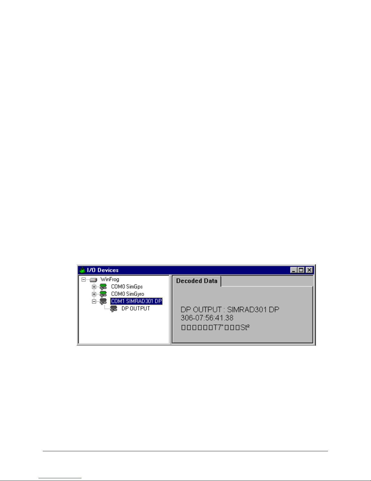
Download Status:
No status is displayed in the I/O Devices Window during the transfer of data from
WinFrog to the Simrad 301. What is shown is the binary data being output, as
displayed below.
Note that the SimGps and SimGyro devices are added to show the output of
data.
WinFrog User’s Guide - Appendix C - Output/Simrad 301 DP Page 3 of 7
Page 4

WINFROG VEHICLE TEXT WINDOW > CONFIGURE VEHICLE DEVICES > DEVICE
> EDIT OPTIONS:
The OUTPUT,SIMRAD301 DP, DP OUTPUT data item is added to the vehicle with the
DP system in use. This vehicle should also be tracking the Survey Line for which you
intend to send the relevant line data, to the DP system. If a Survey Line is not enabled,
or the device is not added to the vehicle, no line segment data will be transferred. The
dialog box below will appear when you attempt to configure the device, and send data
to the DP. This will not change until a tracking line is enabled and the device is added to
the vehicle.
When the SIMRAD301 DP, DP OUTPUT item is edited fr om the Configure Vehicle
Devices dialog box, the Configure DP Output dialog box appears. The Position Source
and the Position Offset tabs must be configured. These items configure the vehicle
position output as described in the type 450 record under Configuration Details.
Position Source:
Three items need to be configured on this tab: Data Type Control, Graphics, and
Data Source Control.
WinFrog User’s Guide - Appendix C - Output/Simrad 301 DP Page 4 of 7
Page 5

Data Type Control:
In Data Type Control, there are three options to choose from: Vehicle CRP
Position, Unfiltered Sensor Derived CRP Position, and Unfiltered Sensor
Position.
Choose the Vehicle CRP Position for filtered position updates re fer e nced to the
vehicles’ Central Reference Point (CRP). The offset input under the Position
Offset tab is added to the CRP position.
The Unfiltered Sensor Derived CRP Position is the same as the above only
unfiltered (or raw) data is output. With this option, filtering can be performed
within the DP unit.
The Unfiltered Sensor Position outputs unfilt e r ed positions from the positioning
sensors location. The offset input under the Position Offset tab is added to the
sensors raw position.
Data Source Control:
The data source depends on the Data Type Control that was selected. If the
Vehicle CRP Position is chosen, the Data Source Control will automatically be
set to VEHICLE, CRP POSITION, and the primary positioning sensor data will be
used. If either the U nfi l tered Sensor Derived CRP Position or the Unfiltered
Sensor Position is chosen in the Data Type Control, then the positioning sensor
can be chosen from the dropdown list under Data Source Control. Here a
secondary positioning sensor can be chosen. It is important to note that the
Unfiltered Sensor Derived CRP Position is based on the chosen sensor, however
the data is related to the CRP. Note that the SimGps, POSITION is used in this
dialog as an example only.
Graphics:
Turning on the Graphics will display the device name and a square at the
location of the SIMRAD301 DP position output. This display appears when the
device is added to the vehicle. This position (grid) can be found in the type 450
record in the fields shown under the Configuration Details section of this
document .
It is advisable to have this option turned on so the position output location can be
visually referenced from the Graphics Window.
Position Offset:
The Offsets From Position Source to Output Position can be configured on this
tab. This means that any offset input here will be applied to the position output from
the Position Source tab options listed above.
WinFrog User’s Guide - Appendix C - Output/Simrad 301 DP Page 5 of 7
Page 6

Offset Source:
The Offset Source can be chosen from the list of offsets for the vehicle, or the
Manual Entry can be used.
Manual Offsets:
If Manual Entry is chosen under the Offset Source, the offsets must be input
here. Offsets are input similar to all offsets in WinFrog.
CONFIGURATION DETAILS:
Interfacing to the DP system should only be performed under the supervision of the
vessels’ electrician or other qualified person as designated by the Captain. After
interfacing, all systems should be thoroughly checked prior to operation. First check that
the correct data is being output from WinFrog, and then check for the input at the DP
system.
Data Output:
The output to the Simrad 301 is binary (BCD), and therefore looks like the following
string when output to a Terminal Program.
ł´ ´Q x¯„bIè ł´ ´Q x¯¯„bIé ł´ ´Q x¯¯„bIé ł´ ´Q x¯¯„bPé ł
´ ´ Q x¯ „bPè ł ´ ´ Q x¯ „bPè ł ´ ´ Q x¯ „bPè ł ´ ´ Q x¯ ¯ „bPé
After ensuring that there is something exiting from WinFrog, the data should be
checked at the DP system.
WinFrog User’s Guide - Appendix C - Output/Simrad 301 DP Page 6 of 7
Page 7

Raw Data Logging (type 450 record):
In WinFrog:
The output from WinFrog (in the program) is as follows:
sprintf(rawStr, "450,%s,%.2f,%.8f,%.8f,%.8f,%.8f,%.3f,%.3f,%.3f,%.8f,%.8f\n",name,
fixTime,centreLat,centreLon,
waypointX,waypointY,desiredBrg,desiredSpeed,desiredRange,
currentX,currentY);
Raw 450 Record:
The raw record that is sent out is as follows:
450,SIMRAD301 DP,981049207.16,46.24042762,-63.19942990,
484606.33122696,5120733.25075906,0.000,0.000,0.000,4846244.23073136,512
07802.12423819
Where:
981049207.16, is the time of the last position.
46.24042762,-63.19942990, is the latitude and longitude of the
vessel position (as described in the Config DP Output Window).
484606.33122696,5120733.25075906, are UTM grid coordinates for the
Waypoint being tracked under Setup Waypoint Tracking in the
Configure Vehicles Window. This is not to be confused with Line
Tracking. I.e. This driver tracks Waypoints, not Line Nodes.
4846244.23073136,51207802.12423819, is the Vessel Position (Grid)
(as described in the Config DP Output Window). This value is
described to the decimeter, not to the metre.
and,
no other data fields are relevant for the Simrad 301 WP device.
Note that Survey Line nodes will not show up in the type 450 raw data file, instead
the Waypoint being tracked (under Setup Waypoint Tracking) will be output to the
raw file. The last initiated Waypoint Tracked will show up in the type 450 record.
WinFrog User’s Guide - Appendix C - Output/Simrad 301 DP Page 7 of 7
 Loading...