

Simplicity TV CO-AXIAL SOCKET,SATELLITE SOCKET,RJ45 CAT6 DATA SOCKET,TELEPHONE (MASTER / SLAVE) SOCKET User Manual
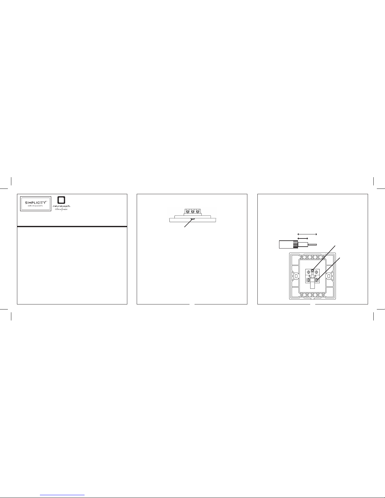
FRONT COVER REMOVAL
Flat aperture recess
To remove trim cover to access xing holes, insert a at headed screw driver into the
aperture on the under side of the switch (as shown) and twist to remove.
INSTALLATION
Important: Please read the information on the previous safety page before
commencing any work.
1. Remove the xing screws (2) from the bag supplied.
2. Undo the terminal screws until they no longer obstruct the cable entry holes.
3. Trim wires to correct length allow cable to reach terminals comfortably.
4. Connect the wires to the correct terminals according to the marking on the
back of the product and wiring diagram.
5. When replacing a switch, take note of the wire positions and terminal markings
on the old switch.
6. Carefully push the wired unit back into the mounting box, ensuring the cables
are not trapped or pinched.
7. Fit and tighten the xing screws as supplied. Do not over tighten the screws as
it may cause damage to the front plate or the mounting box threads.
Technical queries should be made to Retrotouch Technical Sales and Service Depar tment
Tel: +44 (0) 1293 279426 email: support@retrotouch.co.uk
TV CO-AXIAL SOCKET
Step 1. Strip back the rubber sleeve 15mm and inner white plastic core
to 5-8mm, this should leave 7-10mm of conductor length. (as shown)
Step 2. Fold back the braiding over the rubber sleeve (as shown)
Step 3. Insert the cable into the clamp and tighten screws (as shown)
Step 4. Insert conductor into metal xing plate and tighten screw
1 2
SAFETY WARNING
Before use please read carefully and use in accordance with these safety instructions.
This product must be installed by a competent person in accordance with the current
editions of the IEE Wiring Regulations (BS7671) and Buildings Regulations. If in any
doubt, consult a qualied electrician.
These products must not be installed in the same enclosure as equipment rated in excess
of 50V, (e.g. mains rated 13A sockets or switches). Read the instructions carefully before
starting the installation process and keep them safe for future reference.
IF IN ANY DOUBT, PLEASE CONTACT A QUALIFIED ELECTRICIAN.
WARNING
Do not exceed the load rating as shown on the back of the product
Retrotouch (UK) Ltd, Suite 1 Kelvin House, Kelvin Way, Crawley, West Sussex, RH10 9SE.
U.K. Tel: + 44 (0) 1293 279426 Fax: +44 (0) 1293 471444 email: info@retrotouch.co.uk
TV CO-AXIAL / SATELLITE / RJ45 DATA
/ TELEPHONE (MASTER / SLAVE) SOCKET
15mm
5-8mm
Fixing plate
Cable Clamp
RJ45 CAT6 DATA SOCKET
Suitable for use around the home or commercial premises.
TIA Wiring Scheme: See side of product for wire locations
A B
1 - GREEN / white 1 - WHITE / orange
2 - GREEN 2 - ORANGE
3 - ORANGE / white 3 - WHITE / green
4 - BLUE 4 - BLUE
5 - BLUE / white 5 - BLUE / white
6 - ORANGE 6 - GREEN
7 - BROWN / white 7 - BROWN / white
8 - BROWN 8 - BROWN
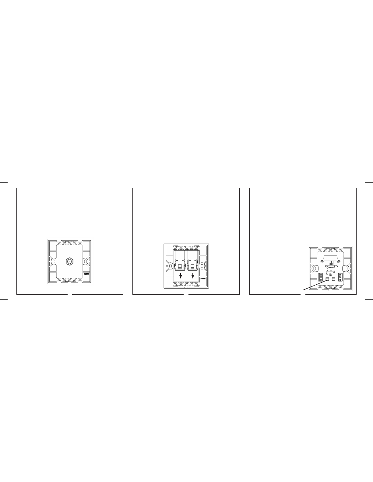
SATELLITE SOCKET
Simplicity Satellite Socket is an ideal solution for use around the home
or ofce.
Please follow the wiring diagram below and ensure the safety warning
and installation guide are read and followed before commencing any
work.
Connect satellite coaxial connector on locating thread and tighten
TELEPHONE (MASTER / SLAVE) SOCKET
All telephone Master and Secondary outlets are tested to BS6312 part 2 under the
OFTEL general approvals for use around the home or ofce.
Master Outlets: Used for the rst socket outlet on a direct exchange line as the
primary Network Termination Point. (Master outlets are surge protected according to
OFTEL requirements as dened in BS6312).
Secondary Outlets: Used as extension sockets when connected on the same line in
parallel with a master socket.
BT Wiring Scheme:
1 - GREEN / white 4 - WHITE / orange
2 - BLUE / white 5 - WHITE / blue
3 - ORANGE / white 6 - WHITE / green
NOTE: Main wire colour is shown in capitals.
43 5
Remove Covers
1
2
3
6
5
4
CABLE TIE FIXING
POINT
 Loading...