

Page 1

User Guide
Page 1
33.6 COMMUNICATOR WITH
™
,
33.6 C
OMMUNICATOR AND
14.4 COMMUNICATOR
STI-FAX/33.6SJ/33.6/14.4V
User Guide
Page 2

Communicator
Page 2
Limited Product Warranty
Simple Technology, Inc. (“STI”), warrants that this product will be free from defects in materials and
workmanship during the warranty period, and will perform according to product documentation.
This warranty is expressly limited to product repair or replacement, at the sole discretion of STI.
Except for the express warranty expressed above, STI grants no other warranty. All implied warranties
of merchantability and fitness for a particular purpose are expressly disclaimed and are not applicable to
the product. This warranty is contingent upon proper use of the product in the application for which it
is intended and does not cover any product that was modified or subjected to unusual physical or
electrical stress.
STI’s maximum liability for breach of, or resulting from, this warranty will be limited to an amount not
exceeding the original product purchase price. In no event will STI be liable to any party for any special,
consequential, or incidental damages, or for damages for personal injury or property damage.
The defective product must be returned to original place of purchase with valid proof of purchase. State
and local laws may apply.
Modem PC Cards Product Warranty Period: 5 Years
Copyright
© Copyright 1996 Simple Technology Inc., all rights reserved. No part of this publication may be
reproduced, transmitted, transcribed, stored in a retrieval system, or translated into any language or
computer language, in any form, by any means, electronic, mechanical, magnetic, optical, chemical,
manual or otherwise, without expressed written consent of STI.
Document Part Number 61600-00003-002
Disclaimer
Specifications subject to change without notice. Simple Technology Inc. makes no representations or
warranties with respect to the contents hereof and specifically disclaims any implied warranties of
merchantability or fitness for any particular purpose. Further, STI reserves the right to revise this
publication and to make changes from time to time in the content hereof without obligation of STI to
notify any person of such revision.
Trademarks
SimpleJack is a trademark and Simple Technology is a registered trademark of Simple Technology, Inc.
Products and brand names are trademarks or registered trademarks of their respective companies.
SimpleJack patent pending.
Page 3

User Guide
Page 3
Contents
1 Introduction ......................................................................................... 4
The 33.6 Communicator with SimpleJack
and 33.6 Communicator ...................................................................... 4
The 14.4 Communicator ...................................................................... 5
Using the Guides .................................................................................. 6
Installation Requirements ..................................................................... 7
Unpacking the Card ............................................................................. 8
Technical Support ................................................................................ 8
2 Describing the Kit ................................................................................. 9
The Hardware ...................................................................................... 9
The Software ...................................................................................... 13
Specifications ..................................................................................... 15
3 Installing the Card .............................................................................. 18
Checking for Card and Socket Services
(Windows 3.x Only) ........................................................................... 18
Plugging in the Card ........................................................................... 19
Attaching the Cables .......................................................................... 21
Installing the Communications Software ............................................. 24
Optional Cellphone Driver Installation
(Windows 3.x and Windows 95 Only) ................................................24
4 Using the Card .................................................................................... 25
Inserting or Removing the Card .......................................................... 25
About Call Waiting ............................................................................. 27
AT Commands, S-Registers, and Result Codes .................................... 27
Protecting the Card ............................................................................ 29
A Troubleshooting .................................................................................. 30
Windows 95 ....................................................................................... 30
Windows 3.1x .................................................................................... 30
B FCC and DOC Compliance .................................................................. 31
C Cellular Data Communication Technology License .............................. 32
Page 4

Communicator
Page 4
1. Introduction
This is a User Guide for the Simple Technology® 33.6 Communicator with
SimpleJack™, 33.6 Communicator and 14.4 Communicator PC Cards.
Refer to the appropriate that follows for an introduction to the features of
your new PC Card.
The 33.6 Communicator with SimpleJack
and 33.6 Communicator
The 33.6 Communicator with SimpleJack and the 33.6 Communicator are
modem PC Cards that feature 33.6 Kbps data transfer, 14.4 Kbps fax,
cellular-ready and voice capabilities. In addition, the 33.6 Communicator
with SimpleJack features a built-in foldaway phone jack permitting
maximum portability. The 33.6 Communicator connects to the phone line
via a line access cable.
These PC Cards allow you to fax and to send and receive data. With
computers that have a microphone and speakers, the voice capabilities of
the PC Cards allow you to use your computer as an answering machine
with voice-mail. With the line access cable (optional for the 33.6 Communi-
cator with SimpleJack), you may use a compatible handset in case your
computer does not have a microphone and speakers.
Also, the PC Cards are cellular ready, featuring Microcom® MNP10
EC™ error correction and compression. The 33.6 Communicator with
SimpleJack features Celeritas® TX-CEL™ transmit spectral shaping.
These features ensure fast and reliable data and fax transmission over
harsh cellular conditions. For use with Microsoft® Windows™␣ 3.x and
Windows 95, optional cellphone cables and drivers for most cellphones
are available from your Simple Technology dealer.
The PC Cards work with PCMCIA Release 2.1 (or higher) Type II
specifications, standard on most laptop and notebook computers. The PC
Cards work with the Card and Socket Services already installed with
Microsoft® Windows™ NT, Windows 95 and Apple® MacOS™ System 7.
The PCMCIA standard facilitates hardware installation—just plug the
card into your computer socket. For Windows 3.x, Windows 95, IBM
®
OS/2® Warp and MacOS System 7 the card features Plug n’ Play. This
allows you to install the card with your operating system already
running.
The credit-card size and Plug n’ Play installation of the card make it ideal
for transferring the modem between computers. This allows you to buy
one modem for use with several computers.
The cards feature Digital Line Guard. This protects the card against highcurrent digital phone lines commonly found in hotels and offices.
Page 5

User Guide
Page 5
The cards are flash upgradeable for fast and easy feature enhancements
should technology change in the future. The flash upgrade utility is
included in the optional cellular cable kit to load cellphone drivers into the
flash. The utility may also be obtained by contacting Simple Technology.
Also included with the cards are communications software for either
Windows␣ 3.x (when used with Microsoft MS-DOS® 5.0 or later) and
Windows 95, or MacOS System 7. Currently, software for MacOS System
7 does not support the cellular and voice features on the cards. For OS/2
Warp or Windows NT, use the cards with your favorite communications
software compatible to OS/2 Warp or Windows NT. Communications
software provides a user interface for the modem. Packaged with the
card is an installation sheet for the communications software.
The 14.4 Communicator
The 14.4 Communicator is a modem PC Card that features 14.4 Kbps
data transfer, 14.4 Kbs fax, cellular-ready and voice capabilities.
The PC Card allows you to send and receive data and fax. For PC
compatibles, the PC Card is cellular ready, featuring MNP10 EC. With an
optional cellphone cable, you can use the data, fax, and voice features of
the card with a cellular phone. The voice capabilities of the card allow
you to use your computer as an answering machine.
The PC Card works with PCMCIA Release 2.1 (or higher) Type II
specifications, standard on most laptop and notebook computers. The PC
Card works with the Card and Socket Services already installed with
Windows NT and Windows 95.
The PCMCIA standard facilitates hardware installation—just plug the
card into your computer socket. For Windows 3.x, Windows 95, and
OS/2 Warp, the card features Plug n’ Play. This allows you to install the
card with your operating system already running.
The credit-card size and easy installation of the card makes it ideal for
carrying the modem between computers. This allows you to buy one
modem for use with several computers.
Also included with the card is communications software for Windows
3.x (when used with Microsoft MS-DOS 5.0 or later) and Windows 95.
For OS/2 Warp or Windows NT, use the card with your favorite communications software compatible to OS/2 Warp or Windows NT.
Communications software provides a user interface for the modem.
Packaged with the card is an installation sheet for the communications
software provided with the card.
Page 6

Communicator
Page 6
Using the Guides
Read the rest of this chapter for information about the Installation
Requirements, Unpacking the Card and Technical Support. Then, read
the chapters as follows:
1. Refer to Chapter 2 for an overview description of the kit
components.
2. Refer to Chapter 3 for instructions on installing the card.
3. Refer to Chapter 4 for further information on using the card,
e.g., inserting and removing the card.
4. Refer to the installation sheet for the communications software
provided or refer to the guide provided with your favorite
compatible communications software for instructions on
installation and start-up of the communications software.
5. With kits for PC compatibles, refer to the TEXT.WRI file on the
Modem Install Diskette for information on the modem AT
commands and S-Registers. The file may be opened and
printed with the Write accessory in Windows 3.x, Windows
NT or OS/2 Warp. For Windows 95, the text may be opened
and printed with the WordPad accessory. With kits for Apple
MacOS System 7, refer to the TEXT.PDF file on the diskettes
included with the kit. The file may be open and printed with
an Acrobat reader. (You may obtain an Acrobat reader from
the Adobe website at adobe.com.)
6. With kits for PC compatibles, refer to Connecting the STI Modem
to Cell Phones flyer for information on obtaining a cable for
your cellphone.
7. Refer to Appendix A for troubleshooting information for PC
compatible installations.
7. Refer to Appendix B for FCC and DOC compliance notices.
8. Refer to Appendix C for information on the cellular data
communication technology license.
Page 7

User Guide
Page 7
Installation Requirements
The following are the minimum requirements for installing the card:
• A computer with the following features:
- An available PC Card Type II socket
- A hard disk drive
- A 3.5-inch floppy disk drive
- For PC compatibles, microphone and speakers if you wish to use
the voice capabilities of the modem (the line access cable—optional
for the 33.6 Communicator with SimpleJack—permits the use of
some handsets for computers without a microphone and speakers)
• With kits for PC compatibles, one of the following operating systems:
- MS-DOS 5.0 or higher, Windows 3.x and Card and Socket
Services compatible to PCMCIA Release 2.1 or higher
- Windows 95
- Windows NT with your favorite Windows NT compatible
communications software
- OS/2 Warp with your favorite OS/2 Warp compatible communications software
• With kits for Apple computers, you need MacOS System 7 or higher
• An available phone line or with kits for PC compatibles, a cellphone
(Cellphone cable and driver for use with Windows 3.x and Windows
95 are optional —refer to flyer included with the card for ordering
information)
Page 8

Communicator
Page 8
Unpacking the Card
The following items are included with your kit:
• 33.6 Communicator with SimpleJack, 33.6 Communicator or
14.4 Communicator
• User Guide
(this document)
• Simple Installation Instructions
• Connecting the STI Modem to Cell Phones flyer
(kits for PC compatibles only)
• Communications Software
(two diskettes)
• Communications Software Installation Sheet
• Diskette
(contains the .INF file and TEXT.WRI for PC compatible kits and
TEXT.PDF for MacOS System 7 kits)
If any item is missing or damaged, contact your dealer immediately.
Technical Support
If you experience any difficulties with the installation of the card or have
any questions regarding the card, contact Simple Technology Technical
Support at the following :
• Tel: 714-476-1180
• 1-800-367-7330 (US and Canada only)
• Fax: 714-476-1209
• EMail: support@simpletech.com
• Website: http://www.simpletech.com
Page 9
User Guide
Page 9
2. Describing the Kit
This chapter describes the kit in the following sections:
• The Hardware
• The Software
• Specifications
The Hardware
Refer to the figures and the descriptions to become familiar with the
hardware:
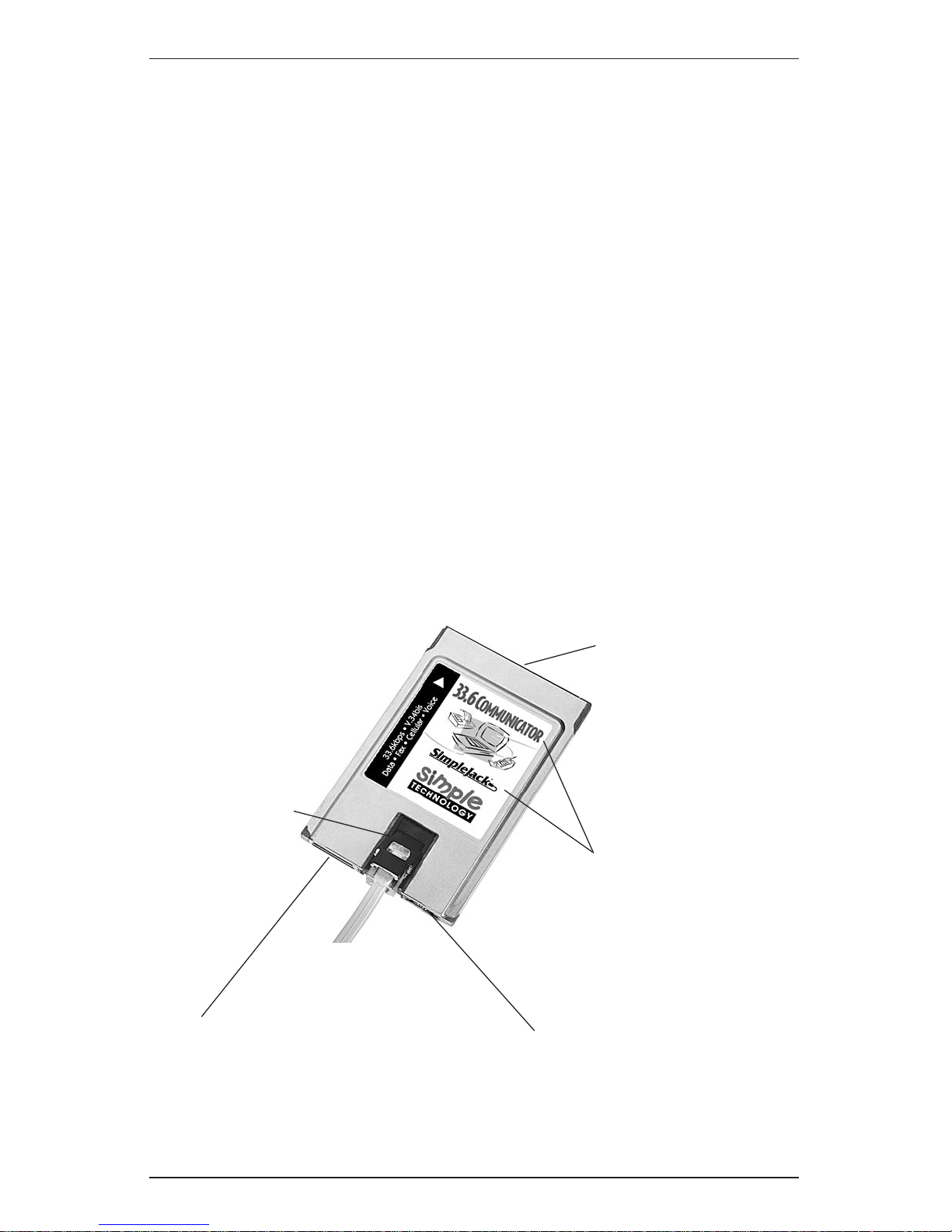
• The PC Card (see Figures 2-1, 2-2 and 2-3). The Type II PC Card contains
a connector for a PC Card socket and a connection for a line access
cable (optional for the 33.6 Communicator with SimpleJack). In
addition, the 33.6 Communicator with SimpleJack features a built-in
foldaway jack and an auxiliary connector for the SimpleJack in case
there is no room to open the SimpleJack when the PC Card is installed.
To use the cellular features, attach the optional cellphone cable to the
line access cable connector. The credit-card size PC Cards are encased
in an ultrasonically welded steel package. The PC Cards are keyed and
will install only in the proper orientation.
Auxiliary Connector for
SimpleJack
Connector for Optional
Cellphone Cable or Optional
Line Access Cable
Identification of Card
(33.6 Communicator
with SimpleJack)
SimpleJack
Connector for PC Card
Socket
Figure 2-1. 33.6 Communicator with SimpleJack
0331
Page 10
Communicator
Page 10
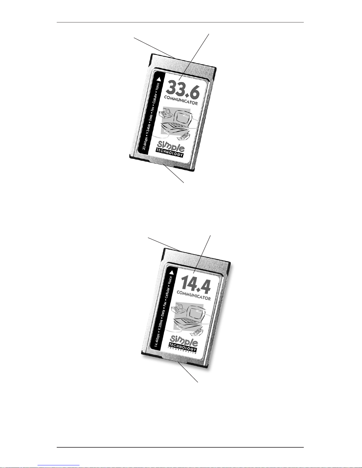
Connector for PC Card
Socket
Connector for Line Access Cable
0332
Identification of Card
(33.6 Communicator)
Figure 2-2. 33.6 Communicator
Figure 2-3. 14.4 Communicator
Connector for PC Card
Socket
Connector for Line Access Cable
0153
Identification of Card
(14.4 Communicator)
Page 11

User Guide
Page 11
• The SimpleJack Connector (see Figure 2-4). This built-in foldaway
jack for the 33.6 Communicator with SimpleJack allows you to
use the modem without the line access cable, providing for
maximum portability. To connect a phone line, simply lift the
hinged top of the jack. In case there is no room to open the jack,
simply slide the jack out and attach the jack to the connector on
the right. Extra SimpleJacks are available from your Simple
Technology dealer.
• The Optional Cellphone Cable. This optional cable for use with PC
compatibles and Windows 3.x and Windows 95 contains a connector
for the card and a custom connector for your cellphone model.
Cellphone cables with drivers are available for most cellphone
models and your PC compatible from your Simple Technology
dealer. For ordering information, refer to the flyer included with the
modem.
Figure 2-4. Simple Jack
0218
SimpleJack
Page 12

Communicator
Page 12
• Line Access Cable (see Figure 2-5). When using the voice features of the
the PC compatible card, this cable allows you to connect a handset
for computers without a microphone and speaker.
This cable is optional for the 33.6 Communicator with SimpleJack and
is for use when the SimpleJack connector is not appropriate for your
application. For purchasing information, call 1-800-4SIMPLE.
This cable is included with the 33.6 Communicator and the 14.4
Communicator and contains a connector for the card, a standard jack
for a phone line and a jack for a user-supplied handset. The connector
and the jacks are keyed and will install in only the proper orientation.
The connector for the card latches to the card to ensure continuous
connection during use. To remove the cable from the card, press on
the latch-release buttons on both sides of the connector.
The standard jack for the phone line is the wider jack connection
with only two wires.
The jack for the user-supplied handset is the narrower jack
connection with four wires. The handset is for use with the
modem’s voice capabilities.
!
There is no industry standard for the signal polarity of handsets;
therefore, the handset jack does not work with all handsets.
Connector for the PC Card
Latch Release
Buttons
To phone line
To Handset
0109
Figure 2-5. The Line Access Cable
Page 13

User Guide
Page 13
The Software
PC Compatible Kit
Refer to the following descriptions to become familiar with the software
on the diskettes included with the PC compatible cards:
• .INF File. The .INF file is on the “Modem Install Diskette.” This file
provides Plug n’ Play information for Windows 95 to configure the
PC Card. This file is needed only the first time you plug the PC Card
into the socket. Once installed, you do not need to use the diskette
when you plug the PC Card into the socket. Your version of Windows 95 may already have the .INF file installed.
• TEXT.WRI File. The TEXT.WRI file included on the “Modem Install
Diskette” contains a reference of the AT Commands, S-Registers and
Result Codes for advanced users.
• Optional Cellphone Driver. The optional cellphone driver that you use
is specific to the make and model cellphone that you are using.
Cellphone drivers for use with Windows 3.x or Windows 95 and
most cellphone models are provided with the optional cellphone
cable. For ordering information, refer to the flyer included with the
modem.
• Flash Upgrade Utility. The card is flash upgradeable for fast and easy
feature enhancements should technology change in the future. The
flash upgrade utility is included with the optional cellphone cable kit
for downloading cellphone drivers into flash. Also, you may obtain
the flash upgrade utility by contacting Simple Technology.
• Communications software. The communications software is provided
on two diskettes. For Windows 3.x and Windows 95, the communications software provides the user interface to fax and to send and
receive data. Also, the communications software supports the voice
capabilities of the card. (To use the voice features, your computer
must have a microphone and speakers or you must use the line
access cable with your own compatible handset.) Refer to the installation sheet that is provided with the communications software for
instructions about the installation and start-up of the software. For
Windows NT and OS/2 Warp, use your favorite Windows NT and
OS/2 Warp compatible communications software.
Page 14

Communicator
Page 14
MacOS System 7 Compatible Kit
Refer to the following descriptions to become familiar with the software
on the diskettes included with the MacOS System 7 compatible cards:
• Communications software. The communications software is provided
on two diskettes. For MacOS System 7, the communications software
provides the user interface to fax and to send and receive data. Also,
the communications software supports the voice capabilities of the
card. (To use the voice features, your computer must have a microphone and speakers or you must use the line access cable with your
own compatible handset.) Refer to the installation sheet that is
provided with the communications software for instructions about
the installation and start-up of the software.
• TEXT.PDF. The TEXT.PDF file included on the diskette contains a
reference of the AT Commands, S-Registers and Result Codes for
advanced users. You may display or print the text file with an Acrobat
reader.
Page 15

User Guide
Page 15
Specifications
The following sections contain specifications of the cards.
Form Factor
PCMCIA Type II
Data Rates
33600bps* ................................................................................... CCITT V.34bis
28800bps* ...................................................................... CCITT V.34 and V.FC
14400bps ..................................................................................... CCITT V.32bis
9600bps ............................................................................................ CCITT V.32
2400bps ....................................................................................... CCITT V.22bis
300bps .............................................................................................. CCITT V.21
1200/600bps forward, 75bps backward ..................................... CCITT V.23
1200bps ................................................................................................ Bell 212A
0-300bps ................................................................................................. Bell 103
*33.6 Communicator with SimpleJack and 33.6 Communicator only
Fax Rates
14400bps .......................................................................................... CCITT V.17
9600bps ............................................................................................ CCITT V.29
4800bps ....................................................................................... CCITT V.27ter
Data Compression
Up to 4:1 compression ratio .................................................... CCITT V.42bis
Up to 2:1 compression ratio ................................................................. MNP 5
Error Correction
CCITT V.42
MNP 2-4
Data Command Set
Enhanced AT command set
Fax Command Set
CCITT Group 3
Class 1 (EIA-578)
Class 2 (EIA-592)
Page 16

Communicator
Page 16
Voice Features
If you have a PC compatible kit and a computer that has a microphone
and speakers, the voice capabilities of the modem allow you to use the
computer as an answering machine with voice mail. If you have a
computer without a microphone and speakers, the line access cable
(optional for the 33.6 Communicator with SimpleJack) allows you to use
a compatible handset.
Diagnostics
Power-on self test
Local digital loop test
Local analog loop and analog loop self test
Remote digital loop and digital loop self test
Power Consumption
Active mode (off-hook)
for the 33.6 Communicator with SimpleJack
and the 33.6 Communicator ............................................................ 975mW
Active mode (off-hook)
for the 14.4 Communicator.............................................................. 700mW
Standby mode (on-hook) ....................................................................... 40mW
Compatible Operating Systems
The PC compatible kit operates with one of the following groups of
operating systems:
• MS-DOS 5.0 or higher, Windows 3.x, and Card and Socket Services
conforming to PCMCIA Card and Socket Services Release 2.1 or higher
(If a copy of Card and Socket Services is not included with your
computer, a free copy is available from Simple Technology—see
Checking for Card and Socket Services in Chapter 3.)
• Windows 95
• Windows NT with your favorite Windows NT compatible communications software
• OS/2 Warp with your favorite OS/2 Warp compatible communications software
The Apple compatible kit operates with the following operating systems:
• MacOS System 7 (System 7 or higher)
Page 17

User Guide
Page 17
16550 UART
Enhanced UART interface provides buffering of data. This feature is
essential in providing reliable high speed communication, when used in
multi-tasking environments like Windows.
Cellular Capability
Optional cellphone cables and drivers are available for most cellphone
models for use with Windows 3.x and Windows 95. The card has the
following cellular-ready features:
• MNP10 EC error correction/data compression
• TX-CEL transmit spectral shaping
(33.6 Communicator with SimpleJack and 33.6 Communicator only)
Digital Line Guard
The 33.6 Communicator with SimpleJack features digital line guard to
protect the card against high-current digital phone lines commonly
found in hotels and offices.
Flash Upgradeable
The 33.6 Communicator with SimpleJack and the 33.6 Communicator
are flash upgradeable for fast and easy feature enhancements should
technology change in the future.
Connection Interfaces
• Use the SimpleJack connector to connect to a standard phone line
(33.6 Communicator with SimpleJack only)
• Use the line access cable (optional for the 33.6 Communicator with
SimpleJack) to connect to a standard phone line and a compatible
handset
• Use the optional cellphone cable and driver to connect to popular
cellphone models (For use with Windows 3.x and Windows 95 only)
Page 18

Communicator
Page 18
3. Installing the Card
This chapter describes installing the card in the following sections:
• Checking for Card and Socket Services (Windows 3.x only)
• Plugging in the Card
• Attaching the Cables
• Installing the Communications Software
• Installing the Cellphone Driver (Optional)
Checking for Card and Socket Services
(Windows 3.x Only)
!
Do not attempt to install Card and Socket Services if you are
using Windows NT, OS/2 Warp and Windows 95. These
operating systems already support PC Cards and may not
properly operate if you install additional Card and Socket
Serivces.
For installations with Windows NT, OS/2 Warp, Windows 95 and
MacOS System 7, proceed to Plugging in the Card.
For installations with Windows 3.x, you must have Card and Socket
Services Release 2.1 (or higher) installed before using the modem. Card
and Socket Services are typically provided with your computer.
Card and Socket Services are device drivers that handle all of the detecting,
configuring and enabling of any compatible PC Card inserted into the
system. These device drivers are not specific to Simple Technology PC
Cards and will support other PC Cards as well.
If you know that you already have Card and Socket Services Release 2.1
(or higher) installed, proceed to Plugging in the Card.
If you do not know whether you have Card and Socket Services Release
2.1 (or higher) installed and you are using MS-DOS 5 and Windows 3.x,
refer to the documentation provided with your computer to determine if
Card and Socket Services Release 2.1 (or higher) are installed.
Page 19

User Guide
Page 19
If you do not know whether you already have Card and Socket
Services installed and you are using MS-DOS 6 or higher with
Windows 3.x, perform the following:
1. While booting your computer, press <F8>. With MS-DOS 6 or
higher, this will load the drivers in CONFIG.SYS one line at a
time.
2. When prompted, press “Y” to load each driver and look for
messages indicating that Socket Services Release 2.1 (or
higher) and Card Services Release 2.1 (or higher) are loading.
If there are existing Card and Socket Services, proceed to Plugging in
the Card. If Card and Socket Services did not load, call your computer manufacturer to determine if a copy of Card and Socket
Services is available for your computer.
Plugging in the Card
Refer to the section appropriate to your operating system.
!
In most computers, the Simple logo will be facing upward when
plugging the PC Card in the socket. If the PC Card doesn’t
appear to seat properly, try turning the PC Card over. Do not
force the PC Card into the socket under any circumstances.
Windows 3.x with Card and Socket Services Release 2.1 or Higher
Proceed as follows:
1. Start Windows 3.x.
2. Plug the PC Card into the PC Card socket. The computer may
beep when the computer recognizes the card.
Windows NT
Proceed as follows:
!
Windows NT does not support Plug n’ Play. You must plug the
PC Card into the PC Card socket before starting Windows NT.
1. Before starting Windows NT, plug the PC Card into the PC
Card socket.
2. Start Windows NT.
OS/2 Warp
Proceed as follows:
1. Start OS/2 Warp.
2. Plug the PC Card into the PC Card socket.
Page 20

Communicator
Page 20
Windows 95
Proceed as follows:
1. Start Windows 95.
2. Plug the PC Card into the PC Card socket.
3. The computer will respond with a beep, and with a picture of
the PC Card on the right of the task bar.
Or,
Windows may respond with some dialog boxes. Follow
on-screen prompts. If the “New Hardware Found”
window similar to that shown in Figure 3-1 appears, insert
the”Modem Install Diskette” that came with the PC Card.
Make sure “Driver from disk provided by hardware
manufacturer” is selected, then click on “OK.” Follow the
on-screen prompts. If additional drivers are required,
Windows 95 may ask you to insert the original diskettes of
Windows 95. Once this is done, the PC Card will be
automatically recognized and configured when you plug
in the PC Card. (Note that the New Hardware Found
window may refer to the 33.6 Communicator with
SimpleJack and the 33.6 Communicator as the 28.8
Communicator.)
Mac OS
Proceed as follows:
1. Start MacOS System 7.
2. Plug the PC Card into the PC Card socket.
3. The computer will respond with a beep and will mount the PC
Card icon on the desktop.
Figure 3-1. The “New Hardware Found” Window
0200
Page 21

User Guide
Page 21
Attaching the Cables
Refer to SimpleJack, Line Access Cable, or Cellphone Cable (Windows 3.x and
Windows 95 Only) depending on your installation requirements
!
If both a phone line and a cellphone are attached to the
33.6␣ Communicator with SimpleJack, the 33.6 Communicator with
SimpleJack will ignore the phone line and use the cellphone.
SimpleJack
Lift the hinged top of the SimpleJack connector and attach a phone line
(see Figure 3-2). If there is no room to open the jack, slide the jack out and
attach the jack to the connector on the right (see Figure 3-3 on the next
page); then, attach the phone line.
Lift the hinged top.
Attach a phone line.
Figure 3-2. Attaching the Card
0217
0216
Page 22

Communicator
Page 22
0216
Attach SimpleJack to
the right connector.
0217
Attach a phone line.
Figure 3-3. Attaching the Card Using the Auxiliary SimpleJack Connector
Page 23

User Guide
Page 23
Line Access Cable
!
If the SimpleJack connector is not appropriate for your
application, you may use the optional line access cable (Simple
Part Number STI-FAX/CCBL). For purchasing information, call
1-800-4SIMPLE.
Refer to Figures 3-4 and 3-5 and Proceed as follows:
1. If you are using the 33.6 Communicator with SimpleJack: attach
the line access cable to the connector on the left).
Or,
If you are using the 33.6 Communicator or the 14.4
Communicator, attach the line access cable to the only
connector on the bottom of the card.
2. Attach a phone line to the wider, two-wire jack in the Line
Access Cable.
3. If you want to use the voice features and your computer does
not have a microphone and speaker, attach a handset to the
narrower, four-wire jack in the line access cable.
!
There is no industry standard for the signal polarity of handsets;
therefore, the handset jack does not work with all handsets.
Proceed to Installing the Communications Software.
Figure 3-5. 33.6 Communicator with SimpleJack Cable Connectors
0215
Connector for Optional Line
Access Cable and Optional
Cellphone Cable
0109
Connector for the PC Card
To Phone Line
To Handset
Figure 3-4. The Line Access Cable Connectors
Page 24

Communicator
Page 24
Cellphone Cable (Windows 3.x and Windows 95 Only)
For the 33.6 Communicator with SimpleJack, attach the optional cellphone
cable to the connector on the left (see Figure 3-5). For the 33.6 Communica-
tor and the 14.4 Communicator, attach the optional cellphone cable to the
only connector on the bottom of the card.Connect the other end of the
cellphone cable to your cellphone.
Proceed to Installing the Communications Software.
Installing the Communications Software
Use communications software to connect to remote computers, dial bulletin
boards, send electronic mail and to send or receive faxes. If you have a PC
compatible computer with a microphone and speakers or you are using a
handset with the line access cable, use communications software that
supports the voice features of the modem. Be sure to select the appropriate
microphone and speakers when configuring the communications software.
Communications software is provided with the modem for either
Windows 3.x and Windows 95, or MacOS System 7. (MacOS System 7
software is not available for the 14.4 Communicator.) Refer to the
installation sheet supplied with the communications software for
installation and start-up.
The communications software may ask for an initialization string. Use
the following suggested suggested initialization string:
ATE0 V1 &C1 &D2 S95=47.
For Windows NT and OS/2 Warp, use your favorite communications
software compatible to Windows NT or OS/2 Warp. Refer to the guides
that came with the communications software for installation and start-up.
If you have purchased the optional cellphone cable, proceed to Cellphone
Driver Installation (Windows 3.x and Windows 95 Only).
If you are not using the cellphone option, installation is complete.
Proceed to Chapter 4.
Optional Cellphone Driver Installation
(Windows 3.x and Windows 95 Only)
To use the card with cellphones, refer to the installation guide provided
with the optional cellphone cable for information about installing the
cellphone drivers.
Installation is complete. Proceed to Chapter 4.
Page 25

User Guide
Page 25
4. Using the Card
This chapter provides information on the following topics:
• Inserting and Removing the Card
• About Call Waiting
• AT Command Summary
• Protecting the Card
Inserting or Removing the Card
This section consists of Inserting or Removing the Card with Windows 3.x
and OS/2 Warp, Inserting or Removing the Card with Windows NT, Inserting
or Removing the Card with Windows 95 and Inserting or Removing the Card
with MacOS System 7. Refer to the section appropriate to your operating
system.
Inserting or Removing the Card with Windows 3.x and OS/2 Warp
You can insert the card anytime. You can remove the card anytime the
computer is not accessing the card. Some computers will beep when the
computer recognizes the change in status of the PC Card socket. To remove
the card, proceed as follows:
• If your computer has an eject button on the PC Card socket, press the
button to release the card. Then, pull the card from the socket.
OR
• If your computer does not have an eject button on the PC Card
socket, carefully pull the card straight out from the socket.
Proceed to About Call Waiting.
Inserting or Removing the Card with Windows NT
You must insert the card before booting into Windows NT. To remove the
card, you must first exit Windows NT, then proceed as follows:
• If your computer has an eject button on the PC Card socket, press the
button to release the card. Then, pull the card from the socket.
OR,
• If your computer does not have an eject button on the PC Card
socket, carefully pull the card straight out from the socket.
Proceed to About Call Waiting.
Page 26

Communicator
Page 26
Inserting or Removing the Card with Windows 95
You can insert the card at anytime. When you are done using the card, it
is recommended that you “stop” the card before removing the card.
Proceed as follows:
1. Double-click with the normal-select mouse button on the
PCMCIA icon located on the right of the task bar. The “PC
Card Properties” window appears (see Figure 4-1). Select the
card from the list. Click on the “Stop” button. When prompted
to remove the card, proceed to Step 2. (Note that the PC Card
Properties window may refer to the 33.6 Communicator
with SimpleJack and the 33.6 Communicator as the 28.8
Communicator.)
Figure 4-1. “PC Card Properties” Window
0210
2. If your computer has an eject button on the PC Card socket,
press the button to release the card. Then, pull the card from
the socket.
OR
If your computer does not have an eject button on the PC Card
socket, carefully pull the card straight out from the socket.
Proceed to About Call Waiting.
Page 27

User Guide
Page 27
Inserting or Removing the Card with MacOS System 7
You can insert the card at anytime and MacOS System 7 will mount the
icon of the card onto the desktop. When you are done using the card,
drag the icon of the card into the trash can and the computer will eject
the card.
About Call Waiting
To ensure that your communication is not interrupted while using
your modem, you should disable the call waiting feature if you have
call waiting. The methods for disabling call waiting vary in different
locations. Instructions for disabling call waiting can usually be found
in the front section of the local telephone directory.
If disabling call waiting is required, you may want to incorporate the
disabling feature into the standard dialing prefix. For example, the standard dialing prefix might be ATX4DT. If the call waiting feature is disabled
by ✱70, you may want to change the dial prefix to ATX4DT✱70.
Call waiting is normally re-enabled after each call.
AT Commands, S-Registers, and Result Codes
Communications software provides a user interface to the modem; therefore, you do not need to understand AT Commands, S-Registers, and
Result Codes to use the modem. Advanced users, however, may display or
print the the Reference Guide text file for more information on AT Commands, S-Registers, and Result Codes. Table 4-1 provides a summary of the
most frequently used AT Commands.
Page 28

Communicator
Page 28
Table 4-1. AT Command Summary
AT Command prefix used to begin almost all commands.
Commands preceded by AT and followed by <Enter>:
D Dial the following number using the default or previous
method (tone or pulse).
DT Dial the following number using tones.
DP Dial the following number using pulses.
DS=n Dial stored number n.
W Wait for dial tone before dialing.
H Hang up the phone.
O Go on-line (switch from command mode to data mode).
Used to resume interrupted communications when the
remote modem is still on-line.
Sr? Read S-register r.
Sr=n Write value n to S-register r.
Zn Reset and recall saved profile n.
&Fn Recall factory configuration n.
&V Display current configuration and stored profiles.
&Wn Save current configuration as profile n.
&Zn=x Save x as stored telephone number n.
Command not preceded by AT and not followed by <Enter>:
A/ Repeat the previous command.
Page 29

User Guide
Page 29
Protecting the Card
Observe the following points:
• Do not drop the card.
• Never remove the card when the computer is accessing the card.
• Place the computer and peripherals out of direct sunlight, high or
low temperatures and high humidity.
• Do not turn the computer or peripherals on and off in rapid
succession.
• Keep all vents in the computer and peripherals free from obstruction,
e.g., books, papers, etc.
• Use a power line conditioner in environments where power surges
are likely, e.g., near heavy machinery, fluorescent lights, etc.
Page 30

Communicator
Page 30
A. Troubleshooting
Windows 95
To verify that the modem is configured after installing the modem into a
computer with Windows 95, proceed as follows:
1. Double-click on My Computer. Double-click on Control Panel.
Double-click on Modems.
2. Click on the General tab and look for the Communicator (see
Figure A-1). If the Communicator is listed, click on the
Diagnostics tab. (Note that the Modem Properties window
may refer to the 33.6 Communicator with SimpleJack and
the 33.6 Communicator as the 28.8 Communicator.)
3. In Diagnostics, highlight the COM Port next to the
Communicator, and then click on More Info.
If Windows 95 reports several AT commands with a response next to
each command, then the modem is properly installed.
Windows 3.1x
Refer to Checking for Card and Socket Services on Pages 18 and 19 and make
sure Card and Socket Services Release 2.1 or higher is installed.
Figure A-1. Checking for the Modem in the General Tab
0330
Page 31

User Guide
Page 31
B. FCC and DOC Compliance
The following statements are provided in accordance with Federal Communications Commission (FCC)
and Canadian Department of Communications (DOC). Please read these statements carefully before
installing or operating your modem.
FCC Part 68 Requirements
This equipment complies with Part 68 of the FCC Rules. On the bottom of this equipment is a label that
contains, among other information, the FCC Registration Number and Ringer Equivalence Number
(REN) for this equipment. If requested, this information must be given to the telephone company.
The REN is used to determine the maximum number of devices connected to your telephone line that
will ring in response to an incoming call. In most, but not all, areas, the total REN of devices connected
to a line should not exceed five (5.0). To find out the total permitted in your area, contact your local
telephone company.
If your telephone equipment causes harm to the telephone network, the telephone company may
discontinue your service temporarily. If possible, the company will notify you in advance. But if
advance notice isn’t practical, you will be notified as soon as possible. You will also be informed of your
right to file a complaint with the FCC. If your equipment is the cause of the problem, you will be given
the opportunity to correct the problem.
Your telephone company can make changes in its facilities, equipment, operations, or procedures that
could affect the operation of your equipment. If so, you will be notified in advance so you can make the
changes needed to maintain uninterrupted service.
If you experience trouble with this telephone equipment, please contact Simple Technology at 1-800-3677330 for information on obtaining service or repairs. The telephone company may ask that you
disconnect this equipment from the network until the problem has been corrected or until you are sure
that the equipment is not malfunctioning.
This equipment contains no user serviceable parts.
This equipment may not be used on public coin service or party lines.
FCC Part 15 Requirements
This equipment has been tested and found to comply with the limits for a class B digital device,
pursuant to part 15 of the FCC Rules. These limits are designed to provide reasonable protection against
harmful interference in a residential installation. This equipment generates, uses and can radiate radio
frequency energy and if not installed and used in accordance with the instructions, may cause harmful
interference to radio communications. However, there is no guarantee that interference will not occur in
a particular installation. If this equipment does cause harmful interference to radio or television
reception, which can be determined by turning the equipment off and on, the user is encouraged to try
to correct the interference by one or more of the following measures:
• Reorient or relocate the receiving antenna.
• Increase the separation between the equipment and receiver.
• Connect the equipment into an outlet on a circuit different from that to which the receiver is
connected.
• Consult the dealer or an experienced radio/TV technician for help.
The user is cautioned that changes and modifications made to this equipment without the approval of
the manufacturer could void the user’s authority to operate this equipment. There are no userserviceable parts in this equipment. The unit must be returned to the manufacturer for any repairs.
DOC Certification Label
!
The Canadian Department of Communications (DOC) label identifies certified equipment.
This certification means that the equipment meets certain telecommunications network
protective, operational, and safety requirements. The Department does not guarantee the
equipment will operate to the user’s satisfaction.
Before installing this equipment, users should ensure that it is permissible to be connected to the
facilities of the local telecommunications company. The equipment must also be installed using an
acceptable method of connection. In some cases, the company’s inside wiring associated with a single
line individual service may be extended by means of a certified connector assembly (telephone
extension cord). The customer should be aware that compliance with the above conditions may not
prevent degradation of service in some situations.
Repairs to certified equipment should be made by an authorized Canadian maintenance facility
designated by the supplier. Any repairs or alterations made by the user to this equipment, or equipment
malfunctions, may give the telecommunications company cause to request the user to disconnect the
equipment.
Page 32

Communicator
Page 32
Users should ensure for their own protection that the electrical ground connections of the power utility,
telephone lines, and internal metallic water pipe system, if present, are connected together. This
precaution may be particularly important in rural areas.
!
Users should not attempt to make electrical ground connections themselves; contact the
appropriate electric inspection authority or an electrician.
!
The LOAD NUMBER (LN) assigned to each terminal device denotes the percentage of the total
load to be connected to a telephone loop which is used by the device, to prevent overloading.
The termination on a loop may consist of any combination of devices subject only to the
requirement that the sum of the LOAD NUMBERS of all the devices does not exceed 100.
Warranty and Repair Service in Canada
Target Electronics
1111 Flint Rd. #28
Downview ONT M3J 3C7
(416) 665-9902
Etiquette D’Homologation du Ministère des Communications du Canada
!
L’étiquette du ministère des Communications du Canada identifie le matériel homologué. Cette
étiquette certifie que le matériel est conforme à certaines normes de protection, d’exploitation
et de sécurité des réseaux de télécommunications. Le ministère n’assure toutefois pas que le
matériel fonctionnera à la satisfaction de l’utilisateur.
Avant d’installer ce matériel, l’utilisateur doit s’assurer qu’il est permis de le raccorder aux installations
de l’entreprise locale de télécommunications. Le matériel doit également être installé en suivant une
méthode acceptée de raccordement. L’abonné ne doit pas oublier qu’il est possible que la conformité
aux conditions énoncées ci-dessus n’empêchent pas la dégradation du service dans certaines situations.
Les réparations de matériel homologué doivent être effectuées par un centre d’entretien canadien
autorisé désigné par le fournisseur. La compagnie de télécommunications peut demander â l’utilisateur
de débrancher un appareil à la suite de réparations ou de modifications effectuées par l’utilisateur ou à
cause d’un mauvais fonctionnement.
Pour sa propre protection, l’utilisateur doit s’assurer que tous les fils de mise à la terre de la source
d’énergie électrique, des lignes téléphoniques et des canalisations d’eau métalliques, s’il y en a, sont
raccordés ensemble. Cette précaution est particulièrement importante dans les régions rurales.
!
L’utilisateur ne doit pas tenter de faire ces raccordements lui-même, il doit avoir recours à un
service d’inspection des installations électriques ou à un électricien, selon le cas.
!
L’INDICE DE CHARGE (IC) assigné à chaque dispositif terminal indique, pour éviter toute
surcharge, le pourcentage de la charge totale qui peut être raccordé à un circuit téléphonique
bouclé utilisé par ce dispositif. L’extrémité du circuit bouclé peut consister en n’importe quelle
combinaison de dispositifs pourvu que la somme des INDICES DE CHARGE de l’ensemble des
dispositifs ne dépasse pas 100.
DOC Class B Compliance
This digital apparatus does not exceed the class B limits for radio noise emissions from digital apparatus
set out in the radio interference regulations of the Canadian Department of Communications.
Observation des Normes—Classe B
Le présent appareil numérique n’émet pas de bruits radioélectriques dépassant les limites applicables
aux appareils numériques de la Classe B prescrites dans les règlements sur le brouillage radioélectrique
édictés par les Ministère des Communications du Canada.
C. Cellular Data Communication Technology License
This product contains inactivated SPECTRUM CONNECTED cellular data communication technology
which requires a use license from Spectrum Information Technologies, Inc. No such license is provided
with this product and activation without a use license is prohibited. You automatically obtain a license
by purchasing a cellular direct connect cable from Simple Technology, Inc.
 Loading...