

Silicon Laboratories Si475X Series, Si475x-A40, Si475x-A30, Si475x-A55, Si475xC-A55 Programming Manual
...Page 1

AN543
Si475X PROGRAMMING GUIDE
1. Introduction
This document provides an overview of the programming requirements for the Si475x-A10/A20/A30/A40/A55 and
Si475xC-A55 AM/FM receiver. The hardware control interface and software commands are detailed along with
several examples of the required steps to configure the device for various modes of operation. Table 1 provides a
programming guide cross-reference for each Si475x part released by Silicon Labs to date. This programming guide
focuses on the Si475x/5xC-A55 release; however, features, properties, ranges, and defaults that differ from the
Si475x-A10 to Si475x-A40 are noted as well. Refer to previous versions of this document for earlier firmware
revisions.
Table 1. Si475x Firmware Revisions
Part # Part Revision FMRX Component AMRX Component
Si475x-A10 1.0 3.2.3 3.2.3
Si475x-A20 2.0 8.0.8 7.0.5
Si475x-A30 3.0 10.0.8 9.0.6
Si475x-A40 4.0 13.0.11 12.0.10
Si475x-A55 5.5 15.0.2 14.0.1
Si475xC-A55 5.5 15.0.2 14.0.1
2. Overview
This devices in this product family are programmed using commands and responses. To perform an action, the
system controller writes a command byte and associated arguments, which cause the device to execute the given
command. The device will, in turn, provide a response depending on the type of command that was sent.
The device has a slave control interface that allows the system controller to send commands to and receive
responses from the device using 2-wire mode (I
2
C compatible).
3. Terminology
CTS—Clear to send
STC—Seek/Tune Complete
NVM—Non-volatile internal device memory
Device—Refers to the AM/FM Receiver
System Controlle r —Refers to the system microcontroller
CMD—Command byte
ARGn—Argument byte (n = 1 to 7)
STATUS—Status byte
RESPn—Response byte (n = 1 to 15)
Rev. 0.9 10/16 Copyright © 2016 by Silicon Laboratories AN543
Silicon Laboratories Confidential. Information contained herein is covered under non-disclosure agreement (NDA).
Page 2

AN543
SCL
70%
30%
SDA
70%
30%
START
STARTSTOP
t
f:IN
t
r:IN
t
LOW
t
HIGH
t
HD:STA
t
SU:STA
t
SU:STO
t
SP
t
BUF
t
SU:DAT
t
r:IN
t
HD:DAT
t
f:IN,
t
f:OUT
t
PD:DAT
SCL
SDA
(Write)
START STOPADDRESS + R/W ACK DATA ACK DATA ACK
A6-A0, 0
Command
7-0
Arg1
7-0
SDA
(Read)
START STOPADDRESS + R/W ACK DATA ACK DATA ACK
A6-A0, 1
Status
7-0
Response
7-0
4. Control Interface
The Si475x provides an I2C-compatible, 2-wire control interface.
In powerdown mode, all circuitry is disabled except for the device control interface. The device comes out of
powerdown mode when the POWER_UP command is written to the command register. Once in powerup mode,
the device accepts additional commands such as tuning. The device will not accept commands while in
powerdown mode, with the exception of the powerup command. If the system controller writes a command other
than POWER_UP when in powerdown mode, the device does not respond, and the command is ignored.
Setting the RSTB pin low places the device in reset mode. In reset mode, all circuitry is disabled including the
device control interface; registers are set to their default settings, and the control bus is disabled.
4.1. 2-Wire Control Interface
Figure 1 and Figure 2 show the 2-wire control interface read and write timing parameters and diagrams,
respectively. Refer to the Si475x data sheet for timing parameter values.
Figure 1. I2C Control Interface Read and Write Timing Parameters
2 Rev. 0.9
Figure 2. I
2
C Control Interface Read and Write Timing Diagram
Page 3

AN543
Two-wire bus mode uses the SCL and SDA pins for signaling. A transaction begins with the START condition,
which occurs when SDA falls while SCL is high. Next, the system controller drives an 8-bit control word serially on
SDA, which is captured by the device on rising edges of SCL. The control word consists of a seven-bit device
address followed by a read/write bit (read = 1, write = 0). The device acknowledges the control word by driving
SDA low on the next falling edge of SCL.
For write operations, the system controller next sends a data byte on SDA, which is captured by the device on
rising edges of SCL. The device acknowledges each data byte by driving SDA low for one cycle on the next falling
edge of SCL. For each write transaction, the first byte is a command and the following bytes are arguments.
For read operations, after the device has acknowledged the control byte, it will drive an eight-bit data byte on SDA,
changing the state of SDA on the falling edges of SCL. The system controller acknowledges each data byte by
driving SDA low for one cycle on the next falling edge of SCL. If a data byte is not acknowledged by the system
controller, the transaction will end. For each read transaction, the first byte is the status byte and the following bytes
are the response data from the receiver.
A 2-wire transaction ends with the STOP condition, which occurs when SDA rises while SCL is high.
5. Powerup and Powerdown
There are two procedures for powering up a receiver to move it from powerdown mode to the powerup mode. The
first is a powerup from internal receiver memory. The second is a powerup from a firmware component patch that is
stored in system controller memory. Patches can be applied to a firmware component by the system controller via
a download mechanism to address field issues, errata, or adjust device behavior. Patches are encrypted and
unique to a particular device firmware version, cannot be generated by customers, and can be used to replace a
portion of the component (to address errata, for example) or to download an entirely new component. The user
must verify that the device contains the correct base firmware to support the patch as described later in this
section.
It has been noted that some crystals require greater startup current and settling times than others. The procedure
below is meant to apply to a wide variety of such crystals, providing maximum current and 40 ms for crystal
oscillation to stabilize. If there are still difficulties with POWER-UP that may be related to your choice of crystal,
please refer to the settings and hardware options in “AN750: Si475x 4 MHz Crystal Compatibility Power-Up
Procedure”.
Rev. 0.9 3
Page 4

AN543
Supply VA, VD, and VIO while
keeping the RSTB = 0
START
After a minimum of 100 µs,
set RSTB = 1
After a minimum of 100 µs,
continue to the next step
Send second POWER_UP
command for the desired
function (AM, FM)
Commence normal operation
Send POWER_DOWN
command
Send the POWER_UP
command for desired function
(AM, FM)
Wait at least 100 ms
Send command
to force CTS = 1
5.1. Powerup Receiver from Internal Memory
1. Supply VA, VD, and VIO while keeping the RSTB = 0. Power supplies may be sequenced in any order.
2. After a minimum of 100 µs, set RSTB = 1.
3. After a minimum of 100 µs, continue to the next step.
4. Send the POWER_UP command for the desired function (AM, FM).
4 Rev. 0.9
Page 5

Example (with crystal 4 MHz, FM function):
1. Provide the initial POWER_UP Command:
Action Data Description
CMD 0x01 POWER_UP
ARG1 0X77 NORMAL OPERATION, 4 MHz Crystal
ARG2 0x1F SETS CRYSTAL LOAD CAPACITANCE
Note: Change this value to the capacitance that matches the crystal in use.
ARG3 0x27 SETS CRYSTAL BIAS = 7 w/ FASTBOOT
AN543
ARG4 0x00
0x10
0x20
ARG5 0x00 DIGITAL CORE DISABLED/CRYSTAL OSCILLATOR DISABLED
STATUS NO CTS bit returned
2. Apply a wait time of at least 100 ms.
3. Apply the following command:
Action Data Description
CMD 0xFB CONTROL REGISTER WRITE COMMAND
ARG1 0X06 CONTROL REGISTER ADDRESS
ARG2 0x80 FORCES CTS = 1
STATUS NO CTS bit returned
4. Apply the following command:
Action Data Description
CMD 0x01 POWER_UP
ARG1 0X77 NORMAL OPERATION, 4 MHz Crystal
ARG2 0x1F SETS CRYSTAL LOAD CAPACITANCE
ARG3 0x23 SETS CRYSTAL BIAS = 3 w/ FASTBOOT
BOOT LOADER
FM Receive, 4 MHz Crystal
AM Receive, 4 MHz Crystal
Note: Change this value to the capacitance that matches the crystal in use.
ARG4 0x00
0x10
0x20
ARG5 0x11 DIGITAL CORE ENABLED/CRYSTAL OSCILLATOR ENABLED
STATUS CTS = 1
Note: For more details on the external circuit for the 4 MHz crystal, see “AN750: Si475x 4 MHz Crystal Circuit and Power-Up
Procedure”.
5. The device is ready to commence normal operation and accept additional commands. Refer to Figure 3.
BOOT LOADER
FM Receive, 4 MHz Crystal
AM Receive, 4 MHz Crystal
Rev. 0.9 5
Page 6

AN543
VIO
VD
VA
RSTB
SCL
SDA
POWER_UP Command
100 µs min
100 µs min
> 10 µs
Figure 3. Powerup Timing
6. If desired, send the POWER_DOWN command.
Example:
POWER_DOWN Command
Action Data Description
CMD 0x11 POWER_DOWN
ARG1 0x00 Disable oscillator (ARG1 may be omitted with the same result)
STATUS →0x80 CTS = 1
7. It is now possible to move to the powerup state by returning to step 4.
6 Rev. 0.9
Page 7

5.2. Powerup Receiver from a Patch
Supply V A, V D, and VIO
while keeping the RSTB = 0
START
After a minimum of 100 µs,
set RSTB = 1
After a minimu m of 100 µs,
continue to the next step
Send the POWER_UP
command for the desired
function (AM, FM)
Send POWER_DOWN
command
A
B
Verify Firmw are and R OM
revision?
A
B
Send PART_INFO command
Wait at least 100 ms
Send second POWER_UP
command for the desired
function (AM, FM)
C
Send the POWER_UP
command with boot loader
function
Send patch data.
Send the POWER_UP
command for the desired
function (A M, FM )
Commence normal operation.
Send POWER_DOWN
command.
Wait at least 100 ms
Send second POWER_UP
command with bootloader
function
B
C
Send comm and to force
CTS = 1
Send command to force
CTS = 1
AN543
1. Supply VA, VD, and VI0 while keeping the RSTB = 0. Power supplies may be sequenced in any order.
2. After a minimum of 100 µs, set RSTB = 1.
3. After a minimum of 100 µs, proceed to the next step.
4. (Optional – step 1 of 3 to verify part firmware revision and ROM revision.) Both part firmware revision and ROM
revision must be compatible with a partial patch and ROM revision must be compatible with a full patch. Send
the POWER_UP command for the desired function (AM, FM).
Rev. 0.9 7
Page 8

AN543
Example (with crystal 4 MHz, FM function):
1. Provide the initial POWER_UP Command:
Action Data Description
CMD 0x01 POWER_UP
ARG1 0X77 NORMAL OPERATION, 4 MHz Crystal
ARG2 0x1F SETS CRYSTAL LOAD CAPACITANCE
Note: Change this value to the capacitance that matches the crystal in use.
ARG3 0x27 SETS CRYSTAL BIAS = 7 w/ FASTBOOT
ARG4 0x00
0x10
0x20
ARG5 0x00 DIGITAL CORE DISABLED/CRYSTAL OSCILLATOR DISABLED
STATUS NO CTS bit returned
2. Apply a wait time of at least 100 ms.
3. Apply the following command:
Action Data Description
CMD 0xFB CONTROL REGISTER WRITE COMMAND
ARG1 0X06 CONTROL REGISTER ADDRESS
ARG2 0x80 FORCES CTS = 1
STATUS NO CTS bit returned
4. Apply the following command:
Action Data Description
CMD 0x01 POWER_UP
ARG1 0X77 NORMAL OPERATION, 4 MHz Crystal
ARG2 0x1F SETS CRYSTAL LOAD CAPACITANCE
ARG3 0x23 SETS CRYSTAL BIAS = 3 w/ FASTBOOT
BOOT LOADER
FM Receive, 4 MHz Crystal
AM Receive, 4 MHz Crystal
Note: Change this value to the capacitance that matches the crystal in use.
ARG4 0x00
0x10
0x20
ARG5 0x11 DIGITAL CORE ENABLED/CRYSTAL OSCILLATOR ENABLED
STATUS CTS = 1
Note: For more details on the external circuit for the 4 MHz crystal, see “AN750: Si475x 4 MHz Crystal Circuit and Power-Up
Procedure”.
5. (Optional – step 2 of 3 to verify part firmware revision and ROM revision). Verify part firmware revision and
ROM revision. Send the PART_INFO command.
8 Rev. 0.9
BOOT LOADER
FM Receive, 4 MHz Crystal
AM Receive, 4 MHz Crystal
Page 9

AN543
Example:
PART_INFO Command
Action Data Description
CMD 0x02 PART_INFO
STATUS →0x80 CTS = 1
RESP1 →0x06 Chip revision, 6
RESP2 →0x35 Part number (last two digits) 0x35 = 53, or Si4753
RESP3 →0x32 Firmware major revision = ASCII character “2”
RESP4 →0x30 Firmware minor revision = ASCII character “0”
RESP5 →0x00 Firmware build version = 0
RESP6 →0x00 Reserved, values will vary
RESP7 →0x00 Reserved, values will vary
RESP8 →0x04 ROM ID
In this example, the part revision is 2.0.0 and the ROM ID is 4. Ensure that partial patches received from Silicon
Labs are intended for use with the part firmware revision and ROM, and that full patches are intended for use with
the ROM ID as shown in Table 2. It is possible to verify the FM and AM component firmware revisions with the
FUNC_INFO command, however, this is not necessary because there is always a unique mapping of component
revision to part revision.
Table 2. Si475x Firmware and ROM Compatibility
Part # Part Revision ROM ID FM Revision AM Revision
Si475x-A10 1.0 2 3.2.3 3.2.3
Si475x-A20 2.0 4 8.0.8 7.0.5
Si475x-A30 3.0 5 10.0.8 9.0.6
6. (Optional—step 3 of 3 to verify part firmware revision and ROM revision.) Send the POWER_DOWN
command. This step is required before proceeding with the patching procedure if steps 4 and 5 have been
followed.
Example
POWER_DOWN Command
Action Data Description
CMD 0x11 POWER_DOWN
ARG1 0x00 Disable oscillator (ARG1 may be omitted with the same result)
STATUS →0x80 CTS = 1
7. Send the POWER_UP command for boot loader function.
Rev. 0.9 9
Page 10

AN543
Example (with crystal 4 MHz, boot loader function):
1. Provide the initial POWER_UP Command:
Action Data Description
CMD 0x01 POWER_UP
ARG1 0X77 NORMAL OPERATION, 4 MHz Crystal
ARG2 0x1F SETS CRYSTAL LOAD CAPACITANCE
Note: Change this value to the capacitance that matches the crystal in use.
ARG3 0x27 SETS CRYSTAL BIAS = 7 w/ FASTBOOT
ARG4 0x00
0x10
0x20
ARG5 0x00 DIGITAL CORE DISABLED/CRYSTAL OSCILLATOR DISABLED
STATUS NO CTS bit returned
2. Apply a wait time of at least 100 ms.
3. Apply the following command:
Action Data Description
BOOT LOADER
FM Receive, 4 MHz Crystal
AM Receive, 4 MHz Crystal
CMD 0xFB CONTROL REGISTER WRITE COMMAND
ARG1 0X06 CONTROL REGISTER ADDRESS
ARG2 0x80 FORCES CTS = 1
STATUS NO CTS bit returned
4. Apply the following command:
Action Data Description
CMD 0x01 POWER_UP
ARG1 0X77 NORMAL OPERATION, 4 MHz Crystal
ARG2 0x1F SETS CRYSTAL LOAD CAPACITANCE
Note: Change this value to the capacitance that matches the crystal in use.
ARG3 0x23 SETS CRYSTAL BIAS = 3 w/ FASTBOOT
ARG4 0x00
0x10
0x20
ARG5 0x11 DIGITAL CORE ENABLED/CRYSTAL OSCILLATOR ENABLED
STATUS CTS = 1
5. Send the patch data.
BOOT LOADER
FM Receive, 4 MHz Crystal
AM Receive, 4 MHz Crystal
The patch file provided by Silicon Labs typically has a .sg extension. The system controller must send each line of
8 bytes, wait for a CTS, then send the next line of 8 bytes, etc., until the entire patch has been sent. An example
showing the first few lines and final line of a patch file is shown below. Note that the “#” character indicates a
comment and the patch file indicates the required ROM ID for a partial or full download. If the checksum fails, the
part issues an error code, ERR (bit 6 of the STATUS byte received after each 8-byte transfer), and halts. The part
must be reset to recover from this error condition.
10 Rev. 0.9
Page 11

The following is an example of a patch file:
# COPYRIGHT=2011 Silicon Laboratories, Inc.
# GENERATED=13:53 May 23 2011
# ROMID=0x04
# PATCHID=0x228C
# REQUIRES=NONE
# SIZE=8272
# FUNCTION=FMRX
# MAJOR=8
# MINOR=0
# BUILD=8
# CRCT=0x81CF
# CRCM=0x0A6C
# CRCP=0xEC8D
# CRCX=0x66EE
AN543
# CRCY=0x6381
# CRCZ=0xA805
0x04,0x11,0x81,0xCF,0x00,0x00,0x0D,0xC6
0x05,0xAE,0xE1,0xBD,0xB4,0x90,0x07,0x33
0x06,0xD9,0x3D,0x11,0xF7,0x25,0xCB,0x06
0x17,0x7A,0xF8,0xD0,0x71,0x10,0x3F,0xB7
0x1F,0xBF,0xFF,0x7E,0x42,0xE7,0x53,0x05
…
[Additional Lines]
…
0x08,0x21,0xAB,0xB5,0xF1,0x7A,0xD6,0x5A
0x08,0x10,0x0E,0x9E,0x3B,0xD1,0x01,0xF4
0x08,0xBF,0x8D,0x94,0xB0,0x2D,0xCF,0xFF
0x05,0x8D,0xB1,0x22,0xF2,0x8D,0x22,0x8C
# END
Rev. 0.9 11
Page 12

AN543
Example:
First line of the patch file example
Action Data Description
CMD 0x04
ARG1 0x11
ARG2 0x81
ARG3 0xCF
ARG4 0x00
ARG5 0x00
ARG6 0x0D
ARG7 0xC6
STATUS →0x80 CTS = 1
Second line of the patch file example
CMD 0x05
ARG1 0xAE
ARG2 0xE1
ARG3 0xBD
ARG4 0xB4
ARG5 0x90
ARG6 0x07
ARG7 0x33
STATUS →0x80 CTS = 1
6. Send the POWER_UP command for the desired function (AM, FM).
Example (with crystal 4 MHz, FM function):
POWER_UP Command
Action Data Description
CMD 0x01 POWER_UP
ARG1 0x77 Normal operation
ARG2 0x27 Crystal load capacitance = 15.803 pF each pin
ARG3 0x23 Disables CTS interrupt, crystal bias = 3, enable fastboot
ARG4 0x10 FM function, crystal frequency 4 MHz
ARG5 0x11 Crystal
STATUS →0x80 CTS = 1
Example (with external clock 4 MHz, FM function):
12 Rev. 0.9
Page 13

POWER_UP Command
Action Data Description
CMD 0x01 POWER_UP
ARG1 0x77 Normal operation
ARG2 0x00 Crystal load capacitance = 5 pF each pin
ARG3 0x23 Disables CTS interrupt, crystal bias = 3, enable fastboot
ARG4 0x10 FM function, clock frequency 4 MHz
ARG5 0x12 External clock
STATUS →0x80 CTS = 1
7. The device is ready to commence normal operation and accept additional commands.
8. If desired, send the POWER_DOWN command.
Example:
POWER_DOWN Command
Action Data Description
CMD 0x11 POWER_DOWN
AN543
ARG1 0x00 Disable oscillator (ARG1 may be omitted with the same result)
STATUS →0x80 CTS = 1
9. It is now possible to move to the powerup state by returning to step 7.
Rev. 0.9 13
Page 14

AN543
Command
FM_TUNE_FREQ
Control
Bus
t
STC
t
INT
CTS
Bit
STC
Bit
Command
FM_RSQ_STATUS
INTB
t
CTS
6. Timing
6.1. Command and Property Timing
When the user reads a response over the I2C bus, the first 8 bits returned are the STATUS register. Bit 7 of the
STATUS register is the CTS bit (Clear to Send). When CTS is 1, it indicates that the chip is ready to receive a new
command. Seek and Tune commands may take longer to complete than most other commands, so they also use
the STC bit (Seek/Tune Complete) to indicate they have completed. STC is bit 0 of the STATUS register.
When the user sends any command, the CTS bit will immediately reset to 0. CTS will remain 0 while the chip
processes the command. When the chip is finished processing the command, the CTS bit will be set back to 1.
Before sending another command, the user may poll CTS by reading the first byte of response until CTS = 1. If the
user has enabled the optional CTS interrupt, then the INTB pin will pulse low immediately after CTS has been set
to 1, to notify the user that the previous command has completed. For information on how to enable the CTS
interrupt, see the INT_CTL_ENABLE property and CTSIEN bit in the arguments for the POWER_UP command.
The commands for seek and tune (FM_TUNE_FREQ, FM_SEEK_START, etc.) will cause CTS to reset to 0 for a
short time, but they will set CTS back to 1 after the seek or tune has started. The seek or tune is progressing even
though CTS has been set back to 1. Although the user is free to send another command at this time, it is highly
recommended to wait until the STC (Seek/Tune Complete) bit has been set to 1 before sending another command.
The only exception is the AM/FM_RSQ_STATUS command, which may be sent at any time because it can be used
to cancel the seek/tune in progress and check the status of which station seek is currently on.
When the seek/tune completes, the STC bit will be set to 1. The user may poll STC by reading the first byte of
response until STC = 1. If the user has enabled the optional STC interrupt, then the INTB pin will pulse low
immediately after STC has been set to 1, to notify the user that the seek or tune has completed. For information on
how to enable the STC interrupt, see the INT_CTL_ENABLE property.
After the seek or tune has completed, the user may acknowledge the completion by sending the AM/
FM_RSQ_STATUS command with the STCACK bit set to 1. This will reset the STC bit back to 0. After this, the
user may send another seek or tune command. Alternatively a new seek or tune command will also clear the STC
bit when it begins.
Figure 4 shows a seek or tune command with the optional CTS and STC interrupts enabled. The timing parameters
are shown in Table 3.
Figure 4. CTS and STC Timing Model
14 Rev. 0.9
Page 15

Table 3. Command Timing Parameters for Common Commands
FM_SEEK_BAND_TOP FM_SEEK_BAND_BOTTOM–
FM_SEEK_FREQ_SPACING
--------------------------------------------------------------------------------------------------------------------------------------------------
1+
t
STC
AN543
Command t
t
CTS
STC
t
INT
POWER_UP 100ms — 3µs
POWER_DOWN <1000 µs — 3 µs
FUNC_INFO <200 µs — 3 µs
SET_PROPERTY <200 µs — 3 µs
GET_PROPERTY <200 µs — 3 µs
GET_INT_STATUS <200 µs — 3 µs
AGC_STATUS <200 µs — 3 µs
ANA_AUDIO_PIN_CFG <200 µs — 3 µs
Table 4. Command Timing Parameters for FM Receiver
Command t
FM_TUNE_FREQ <200 µs 21 ms 3 µs
FM_TUNE_FREQ (fast tune) <200 µs 5 ms 3 µs
FM_SEEK_START <200 µs See Note below. 3 µs
FM_RSQ_STATUS <200 µs — 3 µs
FM_ACF_STATUS <200 µs — 3 µs
t
CTS
STC
t
INT
FM_RDS_STATUS <200 µs — 3 µs
FM_RDS_BLOCKCOUNT <200 µs — 3 µs
*Note: t
is seek time per channel. Total seek time depends on bandwidth, channel spacing, and
STC
number of channels to next valid channel.
Worst case seek time complete for FM_SEEK_START is:
For Si475x-A30, the seek time will require an additional t
spacings other than 200 kHz.
STC
+ t
STC(FAST)
for channel
Table 5. Command Timing Parameters for AM Receiver
Command t
AM_TUNE_FREQ 100 µs 40 ms 3 µs
AM_SEEK_START 100 µs See Note below. 3 µs
AM_RSQ_STATUS 100 µs — 3 µs
AM_ACF_STATUS 100 µs — 3 µs
*Note: t
is seek time per channel. Total seek time depends on bandwidth, channel spacing, and
STC
number of channels to next valid channel.
t
CTS
STC
t
INT
Rev. 0.9 15
Page 16

AN543
AF Tune
command
issued
AF Tune
Initiated
F
1
F1 F
2
AF station metrics qualified:
Above thresholds
Tuner stays on AF station
Audio Audio
F
2
}
F
2
T
2
T
3
T
1
T
1
T1 ~ 0.5 ms
T
2
~ 1 ms
T
3
~ 4.8 ms
6.2. Alternate Frequency (AF) Timing
The Si4754/55/56/57 features a flexible FM tune command that allows for a number of operational choices. While
tuned to the current station, the receiver can quickly tune to candidate FM stations and perform one of three
operations.
1. Tune to the FM station and stay tuned.
2. Tune to the FM station; check the selected signal metrics, and jump back to the original station (AF check).
3. Tune to the FM station; check the selected signal metrics, and decide if the receiver is kept tuned to the FM
station (AF Jump) or re-tuned to the original station.
The timing diagrams for AF tune and AF check are shown in Figure 5 and Figure 6, respectively.
Figure 5. AF Tune Diagram
16 Rev. 0.9
Page 17

AN543
AF Check
command
issued
AF Check
Initiated
F
1
F1 F
2
F
2 F1
F
1
AF Station metrics
measured and qualified.
Tuner jumps back to F
1
Audio Audio
F
2
}
}
T
2
T
4
T
2
T
1
T
1
T1 ~ 0.5 ms
T
2
~ 1 ms
T
4
~ 7 ms
Figure 6. AF Check Timing Diagram
Rev. 0.9 17
Page 18

AN543
Fast Tune
command
issued
Fast Tune
Initiated
F
1
F1 F
2
F
2
Audio
Audio
}
T1 ~ 0.5 ms
T
2
~ 1 ms
T
2
T
1
T
1
6.3. Fast Tune Timing
The timing diagram for fast tune is shown in Figure 7.
Figure 7. Fast Tune Timing Diagram
18 Rev. 0.9
Page 19

7. Commands and Properties
7.1. Common Commands and Properties
The following properties and commands are common to all receiver modes.
Table 6. Common Receiver Command Summary
Number Name Summary
AN543
0x01 POWER_UP
0x02 PART_INFO Returns the part information of the device.
0x11 POWER_DOWN Power-down the device.
0x12 FUNC_INFO Returns the firmware revision and patch revision.
0x13 SET_PROPERTY Sets the value of a property.
0x14 GET_PROPERTY Retrieve a property's value.
0x15 GET_INT_STATUS Read interrupt status bits.
0x17 AGC_STATUS Reports the status of the AGC.
0x1B ANA_AUDIO_PIN_CFG Configures the analog audio pins.
0x1C INTB_PIN_CFG Configures behavior of INTB and A1 pins.
Power-up device and mode selection. Modes include operational
function (AM, FM) and audio interface configuration.
Table 7. Common Receiver Property Summary
Number Name Default Summary
A10 A20 A30 A40 A55
0x0000 INT_CTL_ENABLE
0x0300 AUDIO_ANALOG_VOLUME
0x0301 AUDIO_MUTE
0x0000 0x0000 0x0000 0x0000 0x0000
0 0 000
0x003F 0x003F 0x003F 0x003F 0x003F
63 63 63 63 63
0x0000 0x0000 0x0000 0x0000 0x0000
0 0 000
Rev. 0.9 19
Interrupt enable property.
Sets the analog audio
volume.
Audio mute property.
Page 20

AN543
Table 8. Status Response for the FM Receiver
Bit 76543210
STATUS
Bit Name Function
7CTS
6ERR
5:4 Reserved Values may vary.
3RSQINT
2RDSINT
1ACFINT
0STCINT
CTS ERR XX RSQINT RDSINT ACFINT STCINT
Clear to Send.
0 = Wait before sending next command.
1 = Clear to send next command.
Error.
0=No error.
1=Error.
Received Signal Quality Interrupt.
0 = Received Signal Quality measurement has not been triggered.
1 = Received Signal Quality measurement has been triggered.
Radio Data System Interrupt.
0 = Radio data system interrupt has not been triggered.
1 = Radio data system interrupt has been triggered.
Automatically Controlled Features Interrupt.
0 = ACF measurement has not been triggered.
1 = ACF measurement has been triggered.
Seek/Tune Complete Interrupt.
0 = Tune complete has not been triggered.
1 = Tune complete has been triggered.
20 Rev. 0.9
Page 21

AN543
Table 9. Status Response for the AM Receiver
Bit 76543210
STATUS
Bit Name Function
7CTS
6ERR
5:4 Reserved Values may vary.
3RSQINT
2 Reserved Value may vary.
CTS ERR XX RSQINT X ACFINT STCINT
Clear to Send.
0 = Wait before sending next command.
1 = Clear to send next command.
Error
0=No error.
1=Error.
Received Signal Quality Interrupt
0 = Received Signal Quality measurement has not been triggered.
1 = Received Signal Quality measurement has been triggered.
Automatically Controlled Features Interrupt.
1ACFINT
0STCINT
0 = ACF measurement has not been triggered.
1 = ACF measurement has been triggered.
Seek/Tune Complete Interrupt.
0 = Tune complete has not been triggered. Do not send a new TUNE/SEEK
command.
1 = Tune complete has been triggered. It is safe to send a new TUNE/
SEEK command.
Rev. 0.9 21
Page 22

AN543
If the ERR bit in the STATUS response is set for a command or property, the response is redefined as follows:
Table 10. Response When ERR Bit is Set
Bit 7 6 5 4 3 2 1 0
STATUS CTS 1 XX RSQINT RDSINT ACFINT STCINT
RESP1 ERROR
RESP Bit Name Function
Error definitions.
0x10 = Bad command.
0x11 = Bad ARG1.
0x12 = Bad ARG2.
0x13 = Bad ARG3.
17:0ERROR
0x14 = Bad ARG4.
0x18 = Command busy.
0x20 = Bad internal memory.
0x30 = Bad patch.
0x31 = Bad boot mode.
0x40 = Bad property.
22 Rev. 0.9
Page 23

AN543
7.1.1. Common Receiver Commands
Command 0x01 POWER_UP
The POWER_UP command initiates the boot process to move the device from powerdown to powerup mode. The
boot can occur from internal device memory or a system controller downloaded patch. This command powers up
the device with the specified function (FM Receive and AM Receive). Power-up is complete when the CTS bit is
set. This is the only command that may be sent while the device is powered down. Due to variation of the 4 MHz
crystal from vendor to vendor, two power up commands are required for reliably powering up: a 4 MHz crystal preboot POWER_UP command, and a POWER_UP command to boot the part with the desired function (AM, FM).
Command
Bit 7 6 5 4 3 2 1 0
CMD
ARG1
ARG2 00 XCLOAD[5:0]
ARG3 CTSIEN INTSEL FASTBOOT
ARG4 FUNC[3:0] 0000
ARG5 CTEN[4:0]
0x01
XSTART[7:0]
00 XIBIAS[2:0]
XMODE[2:0]
ARG Bit Name Function
Oscillator startup
01110101 = 4 MHz crystal pre-boot (first command in 4 MHz crystal
1 7:0 XSTART[7:0]
2 7:6 Reserved Always write 00.
2 5:0 XCLOAD[5:0]
3 7 CTSIEN
3 6 INTSEL
3 5 FASTBOOT
3 4:3 Reserved Always write 00.
sequence)
01110111 = boot (normal operation with external clock, or the second
command in a 4 MHz crystal sequence)
Selects the amount of additional on-chip capacitance to be connected
between XTAL1 and gnd and between XTAL2 and gnd. One half of the
capacitance value shown here is the additional load capacitance presented to the xtal. The minimum step size is 0.25 pF. The required value
will be layout-dependent. Range is 0–0x3F (i.e. 5–20.75 pF) The EVB
sets XCLOAD = 0x27.
CTS interrupt enable
0 = Disable.
1 = Enable.
CTS interrupt pin select
0=A1 pin.
1=INTB pin.
Speeds boot time when set. It is required to set this bit with Si475x-A20
and later only.
3 2:0 XBIAS[2:0]
Crystal bias current
3 = 4 MHz crystal or external clock
7 = 4 MHz crystal for boot-up
Rev. 0.9 23
Page 24

AN543
ARG Bit Name Function
Selects the boot function of the device.
0 = Boot Loader.
4 7:4 FUNC[3:0]
4 3:0 Reserved Always write 0000.
5 7:3 CNTEN[4:0]
5 2:0 XMODE[2:0]
1=FM Receive.
2=AM Receive.
Note: Values other than those listed may result in unpredictable behavior.
Enable counter
00000 = 4 MHz crystal pre-boot (first command in 4 MHz crystal
sequence)
00010 = boot (normal operation with external clock, or the second com-
mand in a 4 MHz crystal sequence)
Crystal mode
1 = Crystal
2 = External clock
24 Rev. 0.9
Page 25

AN543
Command 0x02 PART_INFO
The PART_INFO command returns the chip revision, part firmware major, minor, and build revision, and ROM ID.
The command is complete when the CTS bit (and optional interrupt) is set. The command may only be sent in
powerup mode.
Command
Bit76543210
CMD
Response
Bit 7 6 5 4 3 2 1 0
0x02
STATUS
RESP1
RESP2
RESP3
RESP4
RESP5
RESP6
RESP7
RESP8
RESP Bit Name Function
1
2 7:0 PART Part Number, last two digits of part number
3 7:0 PMAJOR Part Major Revision (ASCII Character Value)
4 7:0 PMINOR Part Minor Revision (ASCII Character Value)
CTS ERR XX RSQINT RDSINT ACFINT STCINT
CHIPREV[7:0]
PART[7:0]
PMAJOR[7:0]
PMINOR[7:0]
PBUILD[7:0]
Reserved
Reserved
ROMID[7:0]
7:0 CHIPPREV Chip Revision
5 7:0 PBUILD Part Build Version
6 7:0 Reserved Values may vary.
7 7:0 Reserved Values may vary.
8 7:0 ROMID ROM ID
Rev. 0.9 25
Page 26

AN543
Command 0x11 POWER_DOWN
The POWER_DOWN command moves the device from powerup to powerdown mode. The CTS bit (and optional
interrupt) is set when it is safe to send the next command. This command may only be sent when in powerup
mode. Note that only the POWER_UP command is accepted in powerdown mode. If the system controller writes a
command other than POWER_UP when in powerdown mode, the device will not respond. The device will only
respond when a POWER_UP command is written. It is possible to power down a device and leave the oscillator
running.
Command
Bit76543210
CMD
ARG1 0000000 XOSC
ARG Bit Name Function
1 7:1 Reserved Always write 0000000.
10XOSC
Response
Bit76543210
STATUS
Note: The above response shows status bits for FM Receive mode (see Table 8). See Table 9 for status bits for AM Receive
mode.
CTS ERR XX RSQINT RDSINT ACFINT STCINT
0x11
0 = Full powerdown.
1 = Powerdown and leave oscillator running.
26 Rev. 0.9
Page 27

AN543
Command 0x12 FUNC_INFO
The FUNC_INFO command returns the firmware revision and patch revision for currently-loaded functional mode
firmware (AM and FM). The command is complete when the CTS bit (and optional interrupt) is set. This command
may only be sent in powerup mode.
Command
Bit76543210
CMD
Response
Bit 76543210
STATUS
RESP1 FWMAJOR[7:0]
RESP2 FWMINOR1[7:0]
RESP3 FWMINOR2[7:0]
RESP4 PATCHH[7:0]
RESP5 PATCHL[7:0]
RESP6 FUNC[7:0]
Note: The above response shows status bits for FM Receive mode (see Table 8 on page 20). See Table 9 on page 21 for
status bits for AM Receive mode.
RESP Bit Name Function
1 7:0 FWMAJOR[7:0] Firmware Major Revision.
2 7:0 FWMINOR1[7:0] Firmware Minor1 Revision.
3 7:0 FWMINOR2[7:0] Firmware Minor2 Revision.
4 7:0 PATCHH[7:0] Patch ID High Byte (HEX).
5 7:0 PATCHL[7:0] Patch ID Low Byte (HEX).
6 7:0 FUNC[7:0]
CTS ERR XX RSQINT RDSINT ACFINT STCINT
Returns the current functional mode:
1 = FM Receive
2=AM Receive
0x12
Rev. 0.9 27
Page 28

AN543
Command 0x13 SET_PROPERTY
The SET_PROPERTY command sets the value of a property. The CTS bit (and optional interrupt) is set when it is
safe to send the next command. This command may only be sent in powerup mode.
Command
Bit76543210
CMD
ARG1 00000000
ARG2 PROPH[7:0]
ARG3 PROPL[7:0]
ARG4 PROPDH[7:0]
ARG5 PROPDL[7:0]
ARG Bit Name Function
1 7:0 Reserved Always write to 0.
27:0
37:0
47:4
57:0
PROPH
[7:0]
PROPL
[7:0]
PROPDH
[7:0]
PROPDL
[7:0]
Property Address High Byte
This byte, in combination with PROPL, is used to specify the property to modify.
Property Address Low Byte
This byte, in combination with PROPH, is used to specify the property to modify.
Property Data High Byte
This byte, in combination with PROPDL, is used to set the property value.
Property Data Low Byte
This byte, in combination with PROPDH, is used to set the property value.
0x13
Response
Bit76543210
STATUS
Note: The above response shows status bits for FM Receive mode (see Table 8 on page 20). See Table 9 on page 21 for
status bits for AM Receive mode.
28 Rev. 0.9
CTS ERR XX RSQINT RDSINT ACFINT STCINT
Page 29

AN543
Command 0x14 GET_PROPERTY
The GET_PROPERTY command retrieves a property's value. The CTS bit (and optional interrupt) is set when it is
safe to send the next command. This command may only be sent in powerup mode
Command
Bit76543210
CMD
0x14
ARG1 00000000
ARG2 PROPH[7:0]
ARG3 PROPL[7:0]
ARG Bit Name Function
1 7:0 Reserved Always write 0.
Property Address High Byte.
27:0PROP
[7:0]
H
This byte, in combination with PROPL, is used to specify
the property to get.
Property Address Low Byte.
37:0PROP
[7:0]
L
This byte, in combination with PROPH, is used to specify
the property to get.
Response
Bit 76543210
STATUS
CTS ERR XX RSQINT RDSINT ACFINT STCINT
RESP1 XXXXXXXX
RESP2 PROPD
RESP3 PROPD
Note: The above response shows status bits for FM Receive mode (see Table 8 on page 20). See Table 9 on page 21 for
status bits for AM Receive mode.
[7:0]
H
[7:0]
L
RESP Bit Name Function
1 7:0 Reserved Response values may vary.
27:0PROPD
[7:0] Property Data High Byte.
H
This byte, in combination with PROPDL, represents
the requested property value.
37:0PROPD
[7:0] Property Data Low Byte.
L
This byte, in combination with PROPDH, represents
the requested property value.
Rev. 0.9 29
Page 30

AN543
Command 0x15 GET_INT_STATUS
The GET_INT_STATUS command updates the bits of the status byte. This command should be called after any
command that sets the STCINT, ACFINT, RDSINT, ASQINT, or RSQINT bits. When polling, this command should
be periodically called to monitor the STATUS byte, and, when using interrupts, this command should be called after
the interrupt is set to update the STATUS byte. The CTS bit (and optional interrupt) is set when it is safe to send the
next command. This command may only be set in powerup mode.
Command
Bit76543210
CMD
Response
Bit 76543210
STATUS
Note: The above response shows status bits for FM Receive mode (see Table 8 on page 20). See Table 9 on page 21 for
status bits for AM Receive mode.
Command 0x17 AGC_STATUS
The AGC_STATUS command reports the current status of the AGC for FM mode. AM_AGC_STATUS (command
0x47) is used in AM/LW/SW modes. The command is complete when the CTS bit (and optional interrupt) is set.
This command may only be sent when in powerup mode.
Bit76543210
CMD
RESP76543210
CTS ERR XX RSQINT RDSINT ACFINT STCINT
0x15
0x17
STATUS
RESP1 XX
RESP2 FMAGC1
RESP3 FMAGC2
RESP4 PGAGAIN
RESP5 FMLNAG
Note: The above response shows status bits for FM Receive mode (see Table 8 on page 20). See Table 9 on page 21 for
status bits for AM Receive mode.
30 Rev. 0.9
CTS ERR XX RSQINT RDSINT ACFINT STCINT
MIXHI MIXLO LNAHI LNALO X X
Page 31
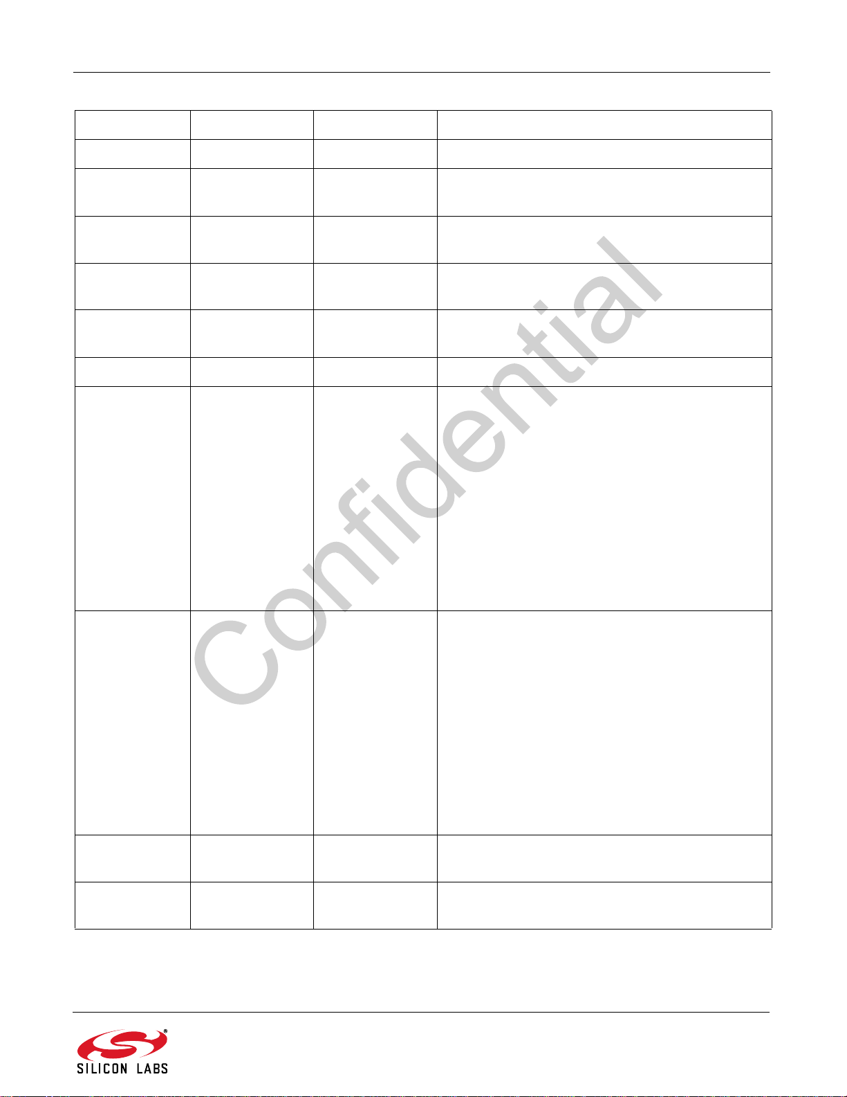
RESP Bit Name Function
1 7:6 Reserved Values may vary.
AN543
15MIXHI
14MIXLO
13LNAHI
12LNALO
1 1:0 Reserved Values may vary.
27:0FMAGC1
0 = FM Mixer PD high threshold is not tripped.
1 = FM Mixer PD high threshold is tripped.
0 = FM Mixer PD low threshold is not tripped.
1 = FM Mixer PD low threshold is tripped.
0 = FM LNA PD high threshold is not tripped.
1 = FM LNA PD high threshold is tripped.
0 = FM LNA PD low threshold is not tripped.
1 = FM LNA PD low threshold is tripped.
The parallel combination of these resistors indicates
the current FMAGC1 attenuator resistance. The total
resistance value at the pin is 800/FMAGC1.
0=10k
1=800
2=400
4=200
8=100
16 = 50
32 = 25
64 = 12.5
128 = 6.25
—no attenuation
The parallel combination of these resistors indicates
the current FMAGC2 attenuator resistance. The total
resistance value at the pin is 800/FMAGC2.
0=10k
1=800
37:0FMAGC2
4 7:0 PGAGAIN
57:0FMLNAG
2=400
4=200
8=100
16 = 50
32 = 25
64 = 12.5
128 = 6.25
PGA gain in dB
Range: 8–33
FM LNA Gain in dB
Range: 2–14
—no attenuation
Rev. 0.9 31
Page 32
AN543
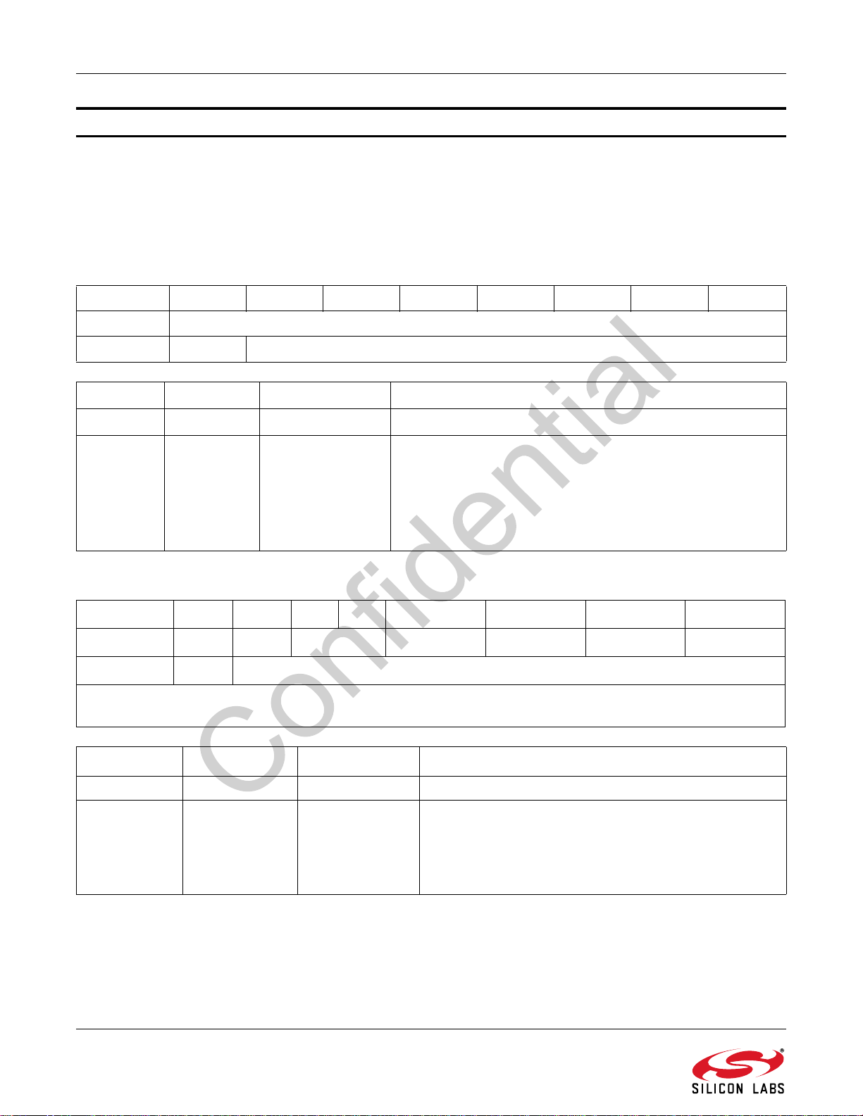
Command 0x1B ANA_AUDIO_PIN_CFG
The ANA_AUDIO_PIN_CFG command configures the analog audio pins. Writing an argument byte to 0 will not
change the state of the pin and is useful when using this command to query the state of the pins. The CTS bit (and
optional interrupt) is set when it is safe to send the next command. This command may only be sent in powerup
mode.
Note: Available in Si475x-A20 and later only.
Command
Bit76543210
CMD
ARG1 0 LROUT[6:0]
ARG Bit Name Function
1 7 Reserved Always write 0.
0 = Do not modify the behavior of this pin.
1 = Disable the output drivers, so the pins are completely inac-
1 6:0 LROUT[6:0]
Response
Bit 7 6 5 4 3 2 1 0
STATUS
RESP1 X LROUT[6:0]
Note: The above response shows status bits for FM Receive mode (see Table 8 on page 20). See Table 9 on page 21 for
status bits for AM Receive mode.
CTS ERR XX RSQINT RDSINT ACFINT STCINT
tive and can be left floating.
2 = Configure the LOUT/ROUT pins to output audio.
3 = Configure LOUT for MPX and disable ROUT
(Si4755/57 only).
0x1B
RESP Bit Name Function
1 7 Reserved Values may vary.
1 = The output drivers are disabled, so the pins are completely inactive and can be left floating.
1 6:0 LROUT[6:0]
32 Rev. 0.9
2 = LOUT/ROUT pins configured to output audio.
3 = LOUT is configured for MPX out (Si4755/57 only) and
ROUT is disabled.
Page 33
AN543
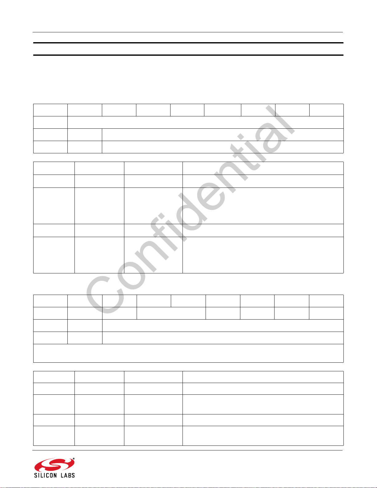
Command 0x1C INTB_PIN_CFG
The INTB_PIN_CFG command configures INTB and A1 pins. Writing an argument byte to 0 will not change the
state of the pin and is useful when using this command to query the state of the pins. The CTS bit (and optional
interrupt) is set when it is safe to send the next command. This command may only be sent in powerup mode.
Command
Bit76543210
CMD
ARG1 0 INTB[6:0]
ARG2 0 A1[6:0]
ARG Bit Name Function
1 7 Reserved Always write to 0.
1 6:0 INTB[6:0]
2 7 Reserved Always write to 0.
26:0A1[6:0]
Response
0x1C
0 = Do not modify the behavior of this pin.
1 = Disable both the output and input drivers so the pin is
completely inactive and can be left floating.
40 = Configure this pin as the interrupt.
0 = Do not modify the behavior of this pin.
1 = Disable both the output and input drivers so the pin is
completely inactive and can be left floating.
40 = Configure this pin as the interrupt.
Bit76543210
Status
RESP1 X INTB[6:0]
RESP 2 X A1[6:0]
Note: The above response shows status bits for FM Receive mode (see Table 8 on page 20). See Table 9 on page 21 for
status bits for AM Receive mode.
RESP Bit Name Function
1 7 Reserved Values may vary.
1 6:0 INTB[6:0]
2 7 Reserved Values may vary.
26:0A1[6:0]
CTS ERR xx RSQINT RDSINT ACFINT STCINT
1 = Disabled.
40 = Configured as the interrupt.
1 = Disabled.
40 = Configured as the interrupt.
Rev. 0.9 33
Page 34
AN543
7.1.2. Common Receiver Properties
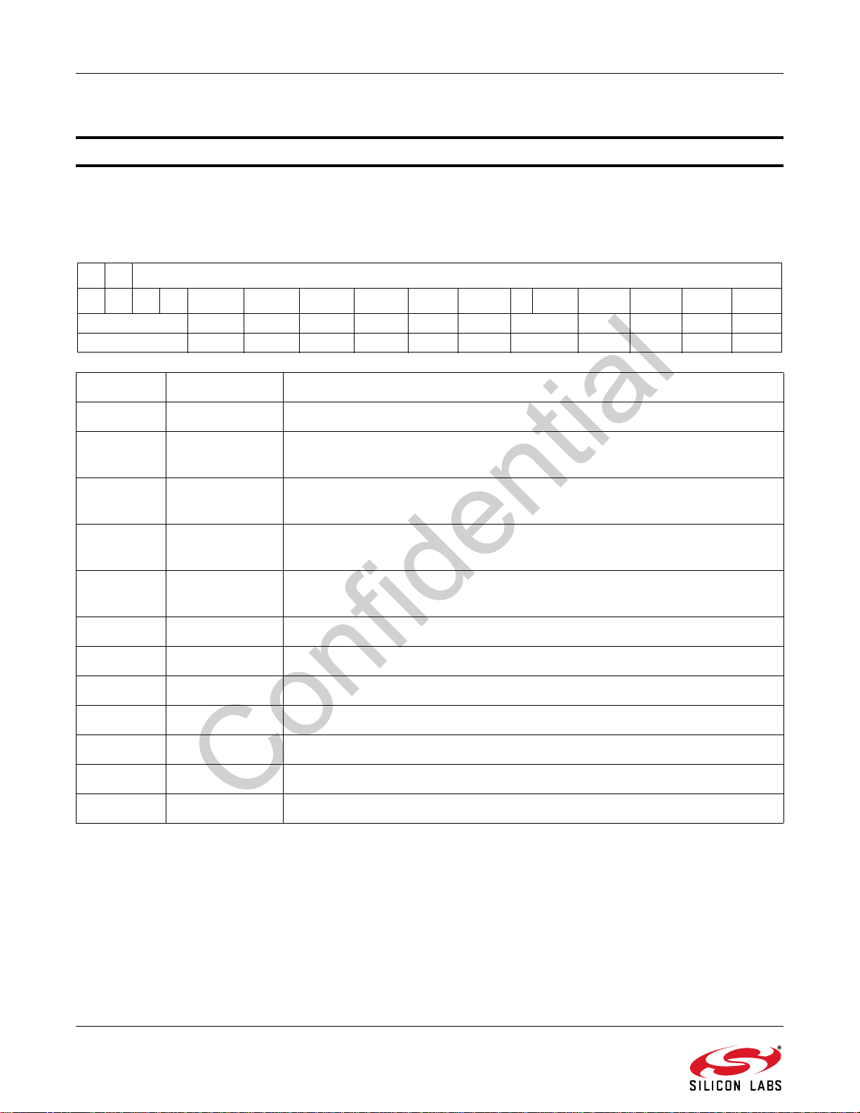
Property 0x0000 INT_CTL_ENABLE
The INT_CTL_ENABLE property enables top-level interrupt sources. The CTS bit (and optional interrupt) is set
when it is safe to send the next command. This property may only be set or read in powerup mode.
Default: 0x0000
INT_CTL_ENABLE
15 14 13 12 11 10 9 8 7 6 5 4 3 2 1 0
0000 RSQREP RDSREP ACFREP STCREP CTSIEN ERRIEN 00 RSQIEN RDSIEN ACFIEN STCIEN
0000 0 0 0 0 0 0 00 0 0 0 0
Bit Name Function
15:12 Reserved Always write 0.
11 RSQREP
10 RDSREP
9 ACFREP
8 STCREP
Repeat interrupt pulse when RSQINT is set, even if a previous interrupt was
generated but not acknowledged.
Repeat interrupt pulse when RDSINT is set, even if a previous interrupt was
generated but not acknowledged.
Repeat interrupt pulse when ACFINT is set, even if a previous interrupt was
generated but not acknowledged.
Repeat interrupt pulse when STCIEN is set, even if a previous interrupt was
generated but not acknowledged.
7 CTSIEN Interrupt when CTS is set.
6 ERRIEN Interrupt when ERR is set.
5:4 Reserved Always write 0.
3 RSQIEN Interrupt when RSQIEN is set.
2 RDSIEN Interrupt when RDSINT is set.
1 ACFIEN Interrupt when ACFINT is set.
0 STCIEN Interrupt when STCIEN is set.
34 Rev. 0.9
Page 35
AN543
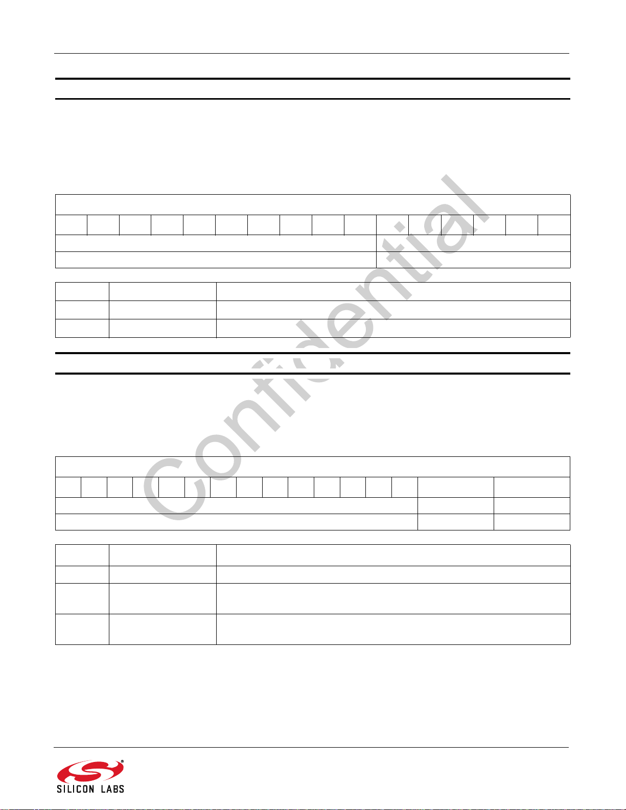
Property 0x0300 AUDIO_ANALOG_VOLUME
The AUDIO_ANALOG_VOLUME property sets the analog audio volume. A value of 0 will mute the audio; a value
of 1 applies 62 dB of attenuation, and a value of 63 applies no attenuation. Each step accounts for 1 dB of change
in the output. The CTS bit (and optional interrupt) is set when it is safe to send the next command. This property
may only be set or read in powerup mode.
Default: 63
AUDIO_ANALOG_VOLUME
1514131211109876543210
0x000 VOL[5:0]
0x000 0x3F
Bit Name Function
15:6 Reserved Always write 0.
5:0 VOL[5:0] Sets the analog audio volume. Default is 63. Range is 0–63.
Property 0x0301 AUDIO_MUTE
The AUDIO_MUTE property mutes/unmutes each audio output (analog left or analog right).The CTS bit (and
optional interrupt) is set when it is safe to send the next command. This property may only be set or read when in
the powerup mode.
Default: 0x0000
AUDIO_MUTE
15141312111098765432 1 0
0x0000 RIGHTMUTE LEFTMUTE
0x0000 0 0
Bit Name Function
15:2 Reserved Always write 0.
1 RIGHTMUTE
0 LEFTMUTE
0 = Right audio is not muted.
1 = Right audio is muted.
0 = Left audio is not muted.
1 = Left audio is muted.
Rev. 0.9 35
Page 36
AN543
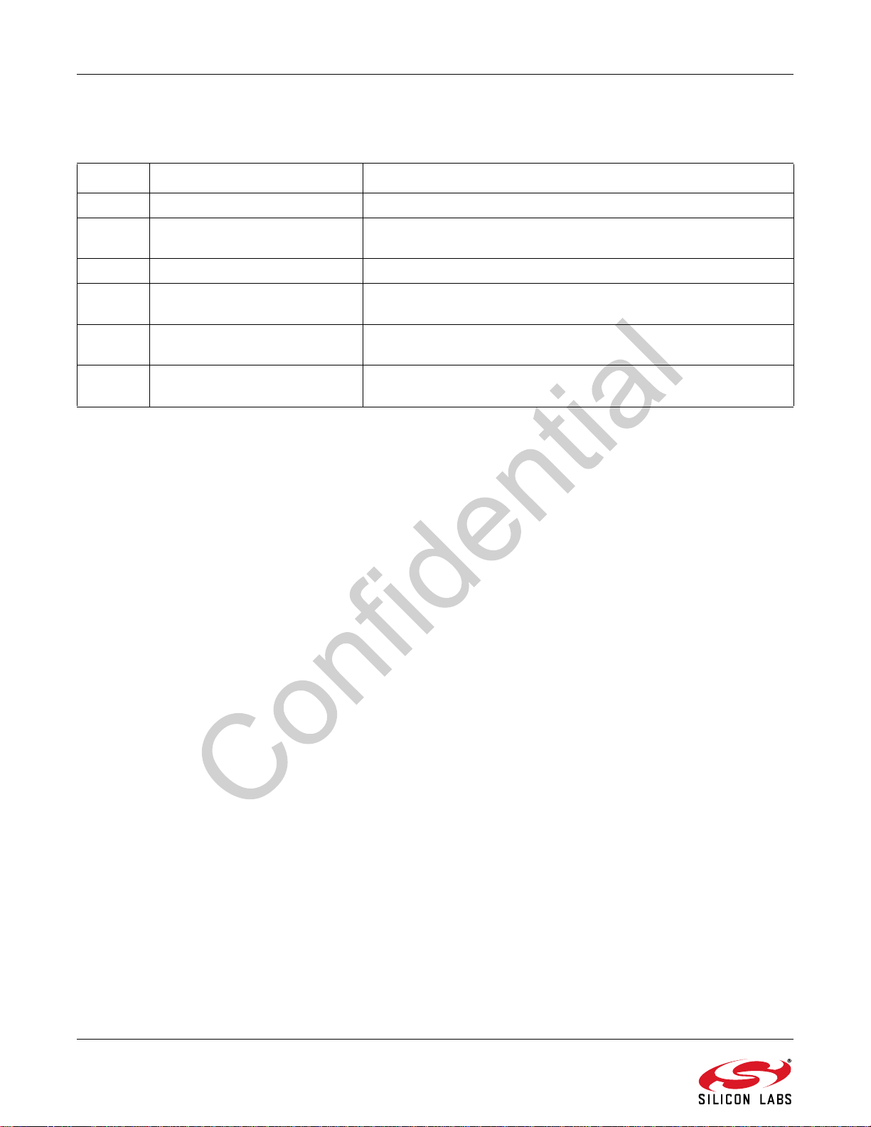
7.2. Commands and Properties for FM Receiver
Table 11. FM Receiver Command Summary
Number Name Summary
0x30 FM_TUNE_FREQ Tunes the FM receiver to a frequency in 10 kHz steps.
0x31 FM_SEEK_START
0x32 FM_RSQ_STATUS Returns status information about the received signal quality.
0x35 FM_ACF_STATUS
0x36 FM_RDS_STATUS
Initiates a seek for a channel that meets the validation criteria for
FM.
Returns status information about automatically-controlled features
for the tuned station.
Returns RDS information for current channel and reads an entry
from the RDS FIFO (Si4751/53/55/57 only).
0x37 FM_RDS_BLOCKCOUNT
Returns RDS expected, received, and uncorrectable block statistic
information (Si4751/53/55/57 only).
36 Rev. 0.9
Page 37
AN543
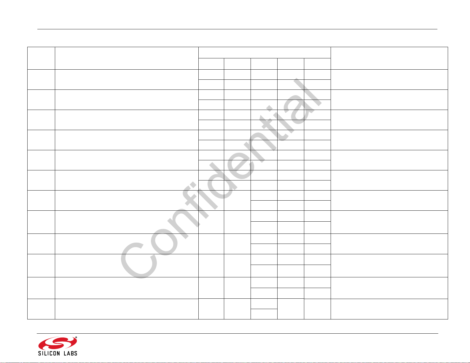
Table 12. FM Receiver Properties Summary
Address Name Default Summary
A10 A20 A30 A40 A55
0x0302 AUDIO_DE_EMPHASIS
0x0000 0x0000 0x0000 0x0000 0x0000
00000
0x0008 0x0008 0x0008 0x0008 0x0008
0x0400 FM_SOFT_MUTE_MAX_ATTENUATION
88888
0x0008 0x0008 0x0008 0x0008 0x0002
0x0401 FM_SOFT_MUTE_TRIGGER_THRESHOLD
88882
0x0000 0x0000 0x0000 0x0000 0x00FA
0x0402 FM_SOFT_MUTE_END_THRESHOLD
0000–6
0x01F4 0x01F4 0x01F4 0x01F4 0x01F4
0x0403 FM_SOFT_MUTE_RELEASE_TIME
500 500 500 500 500
0x0078 0x0078 0x0078 0x0078 0x0078
0x0404 FM_SOFT_MUTE_ATTACK_TIME
120 120 120 120 120
0x0405 FM_SOFT_MUTE_MAX_ATTENUATION_AGC N/A N/A
0x0406 FM_SOFT_MUTE_TRIGGER_THRESHOLD_AGC N/A N/A
0x0407 FM_SOFT_MUTE_END_THRESHOLD_AGC N/A N/A
0x0080 0x0080 0x0080
128 128 128
0x0008 0x0008 0x0008
888
0x0000 0x0000 0x0000
000
Sets the FM Receive de-emphasis.
Sets the maximum soft mute attenuation for
RSSI/SNR softmute engine.
Sets the trigger threshold for RSSI/SNR
softmute engine.
Sets the end threshold for RSSI/SNR softmute engine.
Sets the maximum soft mute release time
ms for RSSI/SNR softmute engine.
Sets the maximum soft mute attack time in
ms for RSSI/SNR softmute engine.
Sets the maximum soft mute attenuation for
RSSI/SNR+AGC softmute engine.
Sets the trigger threshold for RSSI/
SNR+AGC softmute engine.
Sets the end threshold for RSSI/SNR+AGC
softmute engine.
in
0x0408 FM_SOFT_MUTE_RELEASE_TIME_AGC N/A N/A
0x0409 FM_SOFT_MUTE_ATTACK_TIME_AGC N/A N/A
0x040A FM_SOFT_MUTE_USN_LIMITS N/A N/A
Rev. 0.9 37
0x01F4 0x01F4 0x01F4
500 500 500
0x0078 0x0078 0x0078
120 120 120
0x060E
N/A N/A
1550
Sets the maximum soft mute release time in
ms for RSSI/SNR+AGC
Sets the maximum soft mute attack time in
ms for RSSI/SNR+AGC softmute engine.
Set the limits for the USN input metric on
the soft mute mitigation engine.
softmute engine.
Page 38
AN543
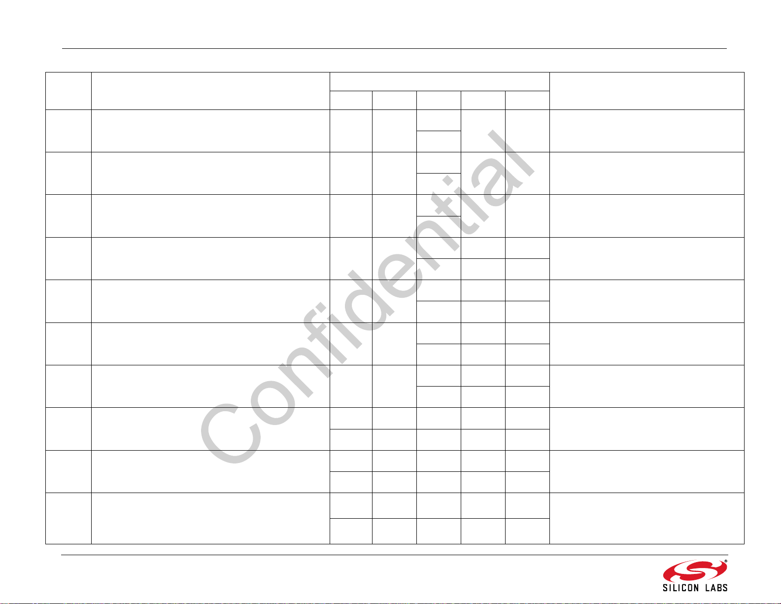
Table 12. FM Receiver Properties Summary (Continued)
Address Name Default Summary
A10 A20 A30 A40 A55
0x040B FM_SOFT_MUTE_USN_ATTENUATION N/A N/A
0x040C FM_SOFT_MUTE_USN_ATTACK_TIME N/A N/A
0x040D FM_SOFT_MUTE_USN_RELEASE_TIME N/A N/A
0x040E FM_SOFT_MUTE_ASSI200_DEV_LIMITS N/A N/A
0x040F FM_SOFT_MUTE_ASSI200_DEV_ATTENUATION N/A N/A
0x0410 FM_SOFT_MUTE_ASSI200_DEV_ATTACK_TIME N/A N/A
0x0411 FM_SOFT_MUTE_ASSI200_DEV_RELEASE_TIME N/A N/A
0x0000
N/A N/A
0
0x0080
N/A N/A USN-based soft mute attack time in ms.
128
0x0100
N/A N/A USN-based soft mute release time in ms.
256
0x335A 0x335A 0x335A
13146 13146 13146
0x0000 0x0000 0x0000
000
0x0080 0x0080 0x0080
128 128 128
0x100 0x100 0x100
256 256 256
Set the limits for the attenuation when
driven by USN on the soft mute mitigation
engine.
Sets the trigger and end thresholds for
ASSI200DEV softmute engine.
Sets the maximum soft mute attenuation for
ASSI200DEV softmute engine.
Sets the maximum soft mute release time
ms for ASSI200DEV softmute engine.
Sets the maximum soft mute attack time in
ms for ASSI200DEV softmute engine.
in
0x0080 0x0080 0x0080 0x0080 0x0080
0x0700 FM_AGC_FE_CONFIG
128 128 128 128 128
0x0270 0x0270 0x0270 0x0270 0x0270
0x0701 FM_AGC_PD_CONFIG
624 624 624 624 624
0x0004 0x0004 0x0004 0x0004 0x0004
0x0702 FM_LNA_AGC_ATTACK_MS
44444
38 Rev. 0.9
Specified the input path for RF signal and
other FE configuration options.
Specifies the behavior of the FM peak
detectors and attenuators.
Sets the number of
band RF high-peak
exceeded before
ate block.
milliseconds the wide-
detector must be
attenuating the appropri-
Page 39
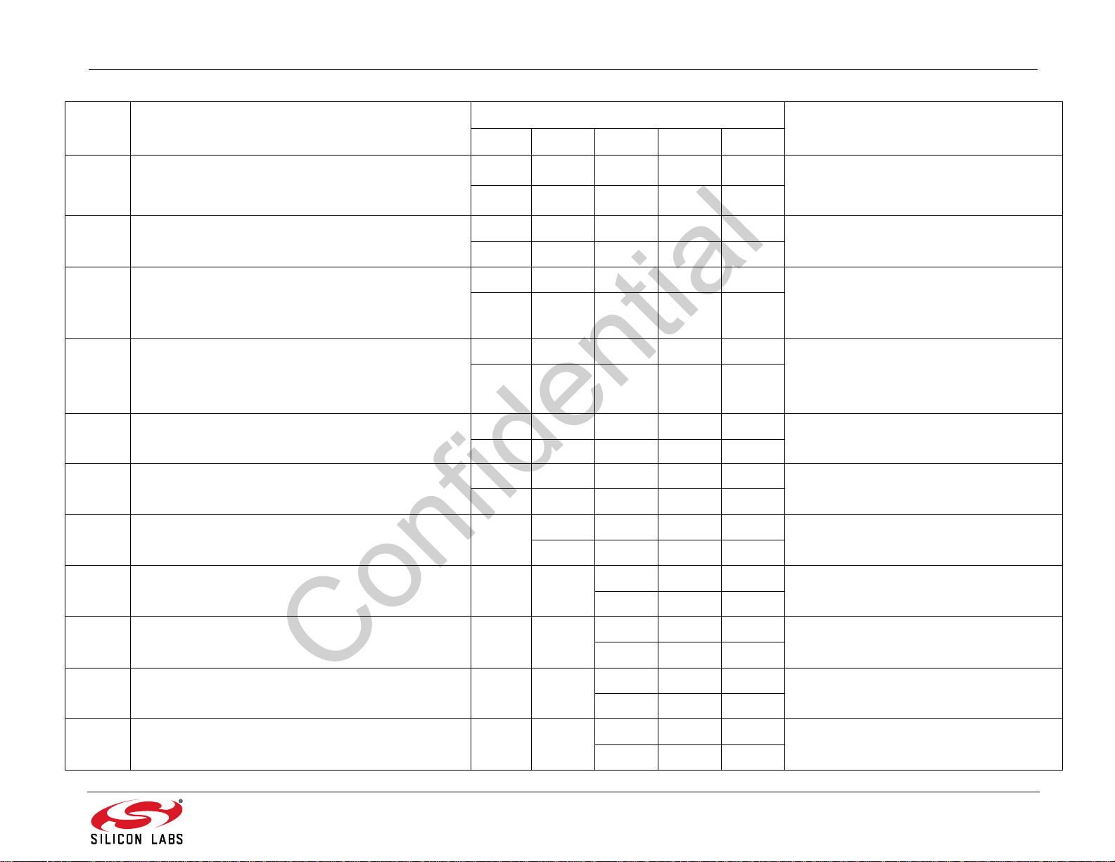
AN543
Table 12. FM Receiver Properties Summary (Continued)
Address Name Default Summary
A10 A20 A30 A40 A55
0x0050 0x0050 0x0050 0x0050 0x0050
0x0703 FM_LNA_AGC_RELEASE_MS
80 80 80 80 80
Sets the number of milliseconds the wideband RF low-peak detector must not be
exceeded before increasing the gain of the
0x0704 FM_LNA_AGC_PD_THRESHOLD
0x4F05 0x4F05 0x4F05 0x4F05 0x4F05
20229 20229 20229 20229 20229
0x0004 0x0004 0x0004 0x0004 0x00F8
0x0705 FM_MIXER_AGC_ATTACK_MS
4444248
0x0050 0x0050 0x0050 0x0050 0x0050
0x0706 FM_MIXER_AGC_RELEASE_MS
80 80 80 80 80
0x5103 0x5103 0x5103 0x5103 0x5103
0x0707 FM_MIXER_AGC_PD_THRESHOLD
20739 20739 20739 20739 20739
0x0000 0x0000 0x0000 0x0000 0x0000
0x0710 FM_AGC_OVERRIDE
00000
0x0000 0x0000 0x0000 0x0000
0x071B FM_AGC_RSSI_OFFSET N/A
0000
0x071C FM_MIXER_AGC_PD_THRESHOLD_MAX N/A N/A
0x071D FM_AGC_RSSI_MIXER_KEY N/A N/A
0x0055 0x0055 0x0059
85 85 89
0x140E 0x140E 0x140E
5134 5134 5134
Sets the high threshold and hysteresis for
the LNA peak detector.
Sets the number of milliseconds the wideband mixer high-peak detector must be
exceeded before attenuating the
ate block.
Sets the number of milliseconds the wideband mixer low-peak detector must not be
exceeded before increasing the gain of the
appropriate block.
Sets the high threshold and hysteresis for
the mixer peak detector.
Overrides the AGC setting by disabling the
AGC and forcing the gain to be maximum.
Offsets the RSSI value so that it can take
into account front-end gain/loss.
Sets the maximum threshold for the mixer
peak detector.
Sets the RSSI threshold and hysteresis to
enable keyed AGC.
appropri-
0x1006 FM_SEEK_TUNE_CHBW_HOLD_TIME N/A
0x1007 FM_TUNE_CHBW N/A N/A
Do not
Write
Rev. 0.9 39
0x0050 0x0050 0x0050
80 80 80
0x0050 0x0050 0x0050
80 80 80
Sets the length of time CHBW is held in unit
of ms.
Sets the maximum CHBW allowed during
the normal tune.
Page 40
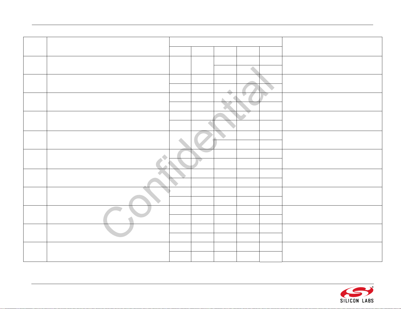
AN543
Table 12. FM Receiver Properties Summary (Continued)
Address Name Default Summary
A10 A20 A30 A40 A55
0x1008 FM_TUNE_AF_CHBW N/A N/A
0x222E 0x222E 0x222E 0x222E 0x222E
0x1100 FM_SEEK_BAND_BOTTOM
8750 8750 8750 8750 8750
0x2A26 0x2A26 0x2A26 0x2A26 0x2A30
0x1101 FM_SEEK_BAND_TOP
10790 10790 10790 10790 10800
0x000A 0x000A 0x000A 0x000A 0x000A
0x1102 FM_SEEK_FREQUENCY_SPACING
10 10 10 10 10
0x1104 FM_SEEK_CHBW N/A N/A
0x0000 0x0000 0x0000 0x0000 0x0000
0x1200 FM_RSQ_INTERRUPT_SOURCE
00000
0x007F 0x007F 0x007F 0x007F 0x007F
0x1201 FM_RSQ_SNR_HIGH_THRESHOLD
127 127 127 127 127
0xFF80 0xFF80 0xFF80 0xFF80 0xFF80
0x1202 FM_RSQ_SNR_LOW_THRESHOLD
–128 –128 –128 –128 –128
0x0096 0x0096 0x0096
150 150 80
0x006E 0x006E 0x0050
110 110 80
Sets the CHBW during the AF tune/check.
Sets the lower seek boundary of the FM
band in multiples of 10 kHz.
Sets the upper seek boundary for the FM
band in multiples of 10 kHz.
Sets the frequency spacing for the FM band
in multiples of 10 kHz when performing a
seek.
Sets the CHBW during the seek.
Configures interrupt related to Received
Signal Quality metrics (FM_RSQ_STATUS).
Sets high threshold which triggers the RSQ
interrupt if the SNR is above this threshold.
Sets low threshold which triggers the RSQ
interrupt if the SNR is below this threshold.
0x1203 FM_RSQ_RSSI_HIGH_THRESHOLD
0x007F 0x007F 0x007F 0x007F 0x007F
127 127 127 127 127
0xFF80 0xFF80 0xFF80 0xFF80 0xFF80
0x1204 FM_RSQ_RSSI_LOW_THRESHOLD
–128 –128 –128 –128 –128
0x007F 0x007F 0x007F 0x007F 0x007F
0x1205 FM_RSQ_ISSI_HIGH_THRESHOLD
127 127 127 127 127
40 Rev. 0.9
Sets high threshold which triggers the RSQ
interrupt if the RSSI is above this threshold.
Sets low threshold which triggers the RSQ
interrupt if the RSSI is below this threshold.
Sets high threshold, which triggers the
interrupt if image signal strength is above
this threshold.
RSQ
Page 41
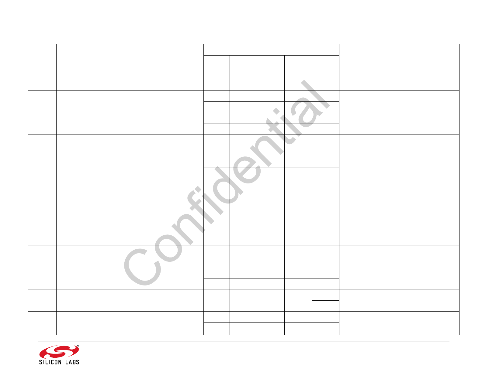
AN543
Table 12. FM Receiver Properties Summary (Continued)
Address Name Default Summary
A10 A20 A30 A40 A55
0xFF80 0xFF80 0xFF80 0xFF80 0xFF80
0x1206 FM_RSQ_ISSI_LOW_THRESHOLD
–128 –128 –128 –128 –128
0x007F 0x007F 0x007F 0x007F 0x007F
0x1207 FM_RSQ_MULTIPATH_HIGH_THRESHOLD
127 127 127 127 127
Sets low threshold which triggers the RSQ
interrupt if image signal strength is below
this threshold.
Sets high threshold which triggers the RSQ
interrupt if Multipath is above this threshold.
0x1208 FM_RSQ_MULTIPATH_LOW_THRESHOLD
0x1300 FM_ACF_INTERRUPT_SOURCE
0x1301 FM_ACF_SM_THRESHOLD
0x1302 FM_ACF_CHBW_THRESHOLD
0x1303 FM_ACF_HICUT_THRESHOLD
0x1304 FM_ACF_HIBLEND_THRESHOLD
0x1305 FM_ACF_BLEND_THRESHOLD
0x1306 FM_ACF_CONTROL_SOURCE
0x0000 0x0000 0x0000 0x0000 0x0000
00000
0x0000 0x0000 0x0000 0x0000 0x0000
00000
0x001F 0x001F 0x001F 0x001F 0x001F
31 31 31 31 31
0x0000 0x0000 0x0000 0x0000 0x0000
00000
0x0000 0x0000 0x0000 0x0000 0x0000
00000
0x0000 0x0000 0x0000 0x0000 0x0000
00000
0x0000 0x0000 0x0000 0x0000 0x0000
00000
0x0001 0x0001 0x0001 0x0001 0x0003
11113
Sets low threshold which triggers the RSQ
interrupt if Multipath is below this threshold.
Enables the ACF interrupt sources.
Sets the softmute interrupt threshold in dB.
Sets the Channel Filter Bandwidth interrupt
threshold in units of kHz.
Sets the HICUT interrupt threshold in units
of 100 Hz.
Sets the HIBLEND interrupt threshold in
units of 100 Hz.
Sets the Stereo Blend interrupt threshold in
units of percent L–R gain.
Sets the controlling metric for ACF features.
0x1307 FM_ACF_HOLD_TIME N/A N/A N/A N/A
0x004B 0x004B 0x004B 0x004B 0x004B
0x2000 FM_VALID_MAX_TUNE_ERROR
75 75 75 75 75
Rev. 0.9 41
0x0064
100
Sets the ACF hold time after tune.
Sets the maximum frequency error in 2
ppm allowed before setting the AFCRL indicator.
Page 42

AN543
Table 12. FM Receiver Properties Summary (Continued)
Address Name Default Summary
A10 A20 A30 A40 A55
0x0006 0x0006 0x0006 0x0006 0x0006
0x2001 FM_VALID_RSSI_TIME
0x2002 FM_VALID_SNR_TIME
0x2003 FM_VALID_SNR_THRESHOLD
0x2004 FM_VALID_RSSI_THRESHOLD
0x2005 FM_VALID_ISSI_THRESHOLD
0x2006 FM_VALID_MULT_THRESHOLD N/Z
0x2007 FM_VALID_AF_TIME N/A
0x2008 FM_VALID_AF_RDS_TIME N/A N/A
66666
0x0012 0x0012 0x0012 0x0012 0x0012
18 18 18 18 18
0x0008 0x0008 0x0008 0x0008 0x0008
88888
0x000C 0x000C 0x000C 0x000C 0x000C
12 12 12 12 12
Do not
write
Do not
write
0x0064 0x0064 0x0064 0x0064
100 100 100 100
0x0005 0x0005 0x0002 0x0002
5522
0x001E 0x001E 0x001E
30 30 30
0x0078 0x0078 0x0078
120 120 120
Sets the amount of time in milliseconds to
allow the RSSI metric to settle before evaluating.
Sets the amount of time in milliseconds to
allow the SNR metric to settle before evaluating.
Sets the SNR threshold for a valid FM Seek
Tune.
Sets the RSSI threshold for a valid FM
Seek Tune.
Sets the ISSI threshold for injection side
switch during FM Seek Tune.
Sets the multipath threshold for a valid FM
Seek/Tune.
Sets the amount of time in milliseconds to
allow the RSSI and SNR metrics to settle
before evaluating during an AF check/tune.
Sets the amount of time in milliseconds to
allow the PI code to be captured before
evaluating.
0x2009 FM_VALID_AF_PI N/A N/A
0x200A FM_VALID_ASSI_THRESHOLD N/A N/A
0x200B FM_VALID_AF_PI_MASK N/A N/A
42 Rev. 0.9
0x0000 0x0000 0x0000
000
0x503C 0x503C 0x503C
20540 20540 20540
0xFFFF 0xFFFF 0xFFFF
65535 65535 65535
Sets the PI code to match during AF tune.
Sets the ASSI/ASSI200 threshold for valid
FM Seek/Tune.
Sets the mask on PI code match during AF
tune.
Page 43
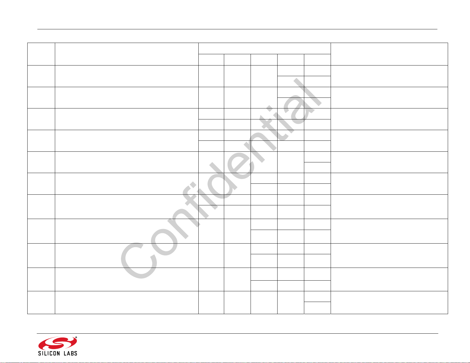
AN543
Table 12. FM Receiver Properties Summary (Continued)
Address Name Default Summary
A10 A20 A30 A40 A55
0x200C FM_VALID_FREQOFF_SCALE N/A N/A N/A
0x0000 0x0000
00
0x0064 0x0064
0x200D FM_VALID_FREQOFF_FILTER N/A N/A N/A
100 100
0x0012 0x0012 0x0012 0x0012 0x0012
0x2100 FM_NB_DETECT_THRESHOLD
18 18 18 18 18
0x0005 0x0005 0x0005 0x0005 0x0005
0x2101 FM_NB_INTERVAL
55555
0x2103 FM_NB_SECONDARY_DETECT_THRESHOLD N/A N/A N/A N/A
0x3500 0x3500 0x1D71
0x2105 FM_NB_WEAK_DETECT_THRESHOLD N/A N/A
13568 13568 7537
0x0032 0x0032 0x0032 0x0032 0x0023
0x2106 FM_NB_STRONG_SIGNAL_SHUTOFF
50 50 50 50 35
0x0000 0x0000 0x0000
0x2109 FM_NB_MODE_CONTROL N/A N/A
000
0x0000
0
Changes FREQOFF from bppm units to
some multiple of Hz.
Changes the amount that FREQOFF is filtered.
Sets the threshold for detecting impulses in
dB above the noise floor.
Sets the interval that original samples are
replaced by interpolated clean samples.
Sets the threshold for detecting impulses in
percentage of average to peak
Sets the threshold for detecting impulses
with the weak signal noise blanker.
The RSSI based shutoff threshold. Used to
turn off the noise blanker under strong signal conditions.
Sets options of the noise blankers.
0x0005 0x0005 0x0005
0x210A FM_NB_WEAK_BLANK_INTERVAL N/A N/A
555
0x0B09 0x0B09 0x0B09
0x210B FM_NB_STRONG_WEAK_SWITCH N/A N/A
2825 2825 2825
0x2111 FM_NB_CIMP_HICUT_LIMIT N/A N/A N/A N/A
Rev. 0.9 43
0x0A14
2580
Number of samples that are replaced by
interpolated clean samples.
Sets the SNR/RSSI thresholds for determining whether strong or weak blanker is
used.
Sets the HiCut multipath threshold when
continuous impulses are detected.
Page 44
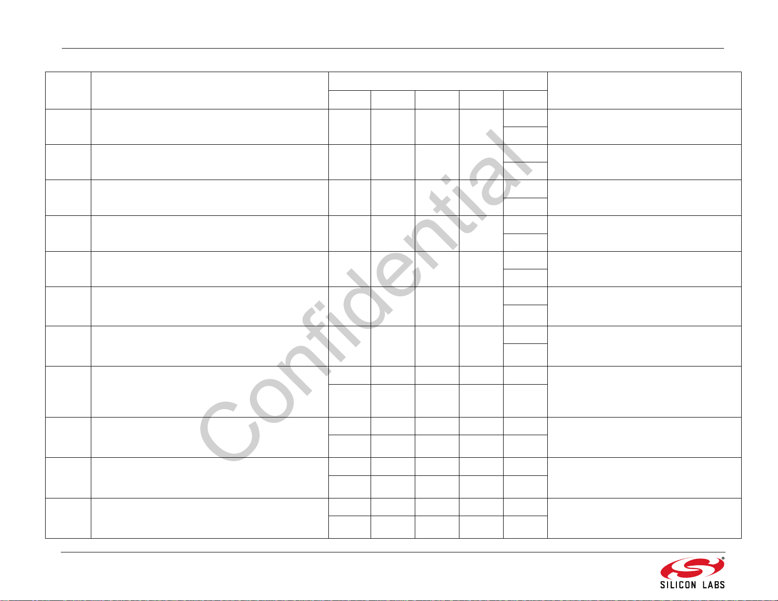
AN543
Table 12. FM Receiver Properties Summary (Continued)
Address Name Default Summary
A10 A20 A30 A40 A55
0x2112 FM_NB_CIMP_HICUT_FREQ N/A N/A N/A N/A
0x2113 FM_NB_CIMP_HICUT_ATTACK N/A N/A N/A N/A
0x2114 FM_NB_CIMP_HICUT_RELEASE N/A N/A N/A N/A
0x2115 FM_NB_CIMP_DETCNTR N/A N/A N/A N/A
0x2116 FM_NB_CIMP_A2PTH N/A N/A N/A N/A
0x2117 FM_NB_CIMP_IMPDET N/A N/A N/A N/A
0x2118 FM_NB_CIMP_MPX_INTV N/A N/A N/A N/A
0x9637 0x9637 0x9637 0x9637 0x9637
0x2200 FM_CHBW_SQ_MIN_MAX
38455 38455 38455 38455 38455
0x000C 0x000C 0x000C 0x000C 0x000C
0x2201 FM_CHBW_SQ_HIGH_THRESHOLD
12 12 12 12 12
0x6401
25601
0x0001
1
0x0008
8
0x0402
1026
0x0800
2048
0x400A
16394
0x0A0A
2570
Sets the HiCut cut-off frequency when continuous impulses are detected.
Sets the HiCut attack time when continuous
impulses are detected.
Sets the HiCut release time when continuous impulses are detected
Continuous impulse detection counter setting.
Independent IQ impulse detection threshold for continuous impulse detection.
Aggressive noise blanker impulse detection
threshold when continuous impulses
detected
Aggressive MPX blanker interval when
continuous impulses detected replacing
property 0x2101
Sets the maximum and minimum channel
filter bandwidth in units of kHz based on
RSSI/STRONGDEV (or SNR) in weak signal condition.
Sets the RSSI/STRONGDEV (or SNR)
threshold for maximum channel filter bandwidth in weak signal condition.
.
.
.
0xFFFC 0xFFFC 0xFFFC 0xFFFC 0x0002
0x2202 FM_CHBW_SQ_LOW_THRESHOLD
–4 –4 –4 –4 2
0x0010 0x0010 0x0010 0x0010 0x0010
0x2203 FM_CHBW_SQ_WIDENING_TIME
16 16 16 16 16
44 Rev. 0.9
Sets the RSSI/STRONGDEV (or SNR)
threshold for minimum channel filter bandwidth in weak signal condition.
Sets the channel filter bandwidth widening
time based on RSSI/STRONGDEV (or
SNR) in weak signal condition.
Page 45
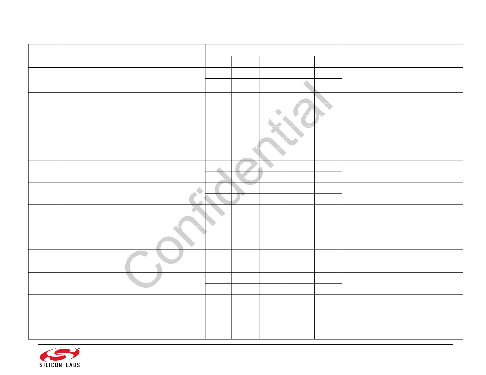
AN543
Table 12. FM Receiver Properties Summary (Continued)
Address Name Default Summary
A10 A20 A30 A40 A55
0x2204 FM_CHBW_SQ_NARROWING_TIME
0x2205 FM_CHBW_ASSI_MIN_MAX
0x2206 FM_CHBW_ASSI_LOW_THRESHOLD
0x2207 FM_CHBW_ASSI_HIGH_THRESHOLD
0x2208 FM_CHBW_ASSI_WIDENING_TIME
0x2209 FM_CHBW_ASSI_NARROWING_TIME
0x220A FM_CHBW_ASSI200_MIN_MAX
0x220B FM_CHBW_ASSI200_LOW_THRESHOLD
0x0800 0x0800 0x0800 0x0800 0x0800
2048 2048 2048 2048 2048
0x9623 0x9623 0x9623 0x9623 0x9623
38435 38435 38435 38435 38435
0x0007 0x0007 0x0007 0x0007 0x0007
77777
0x0014 0x0014 0x0014 0x0014 0x0014
20 20 20 20 20
0x0001 0x0001 0x0C80 0x0C80 0x0C80
1 1 3200 3200 3200
0x0140 0x0140 0x0140 0x0140 0x0140
320 320 320 320 320
0x9632 0x9650 0x9650 0x9650 0x964B
38450 38480 38480 38480 38475
0xFFF6 0xFFF6 0xFFF6 0xFFF6 0x0000
–10 –10 –10 –10 0
Sets the channel filter bandwidth narrowing
time based on RSSI/STRONGDEV (or
SNR) in weak signal condition.
Sets the delta (HASSI,LASSI) threshold for
maximum and minimum channel filter
bandwidth in units of kHz.
Sets the delta (HASSI,LASSI) threshold for
maximum channel filter bandwidth
Sets the delta (HASSI,LASSI) threshold for
minimum channel filter bandwidth.
Sets the channel filter bandwidth widening
time based on the delta (HASSI,LASSI).
Sets the channel filter bandwidth narrowing
time based on the delta (HASSI,LASSI).
Sets the ASSI200 maximum and minimum
channel filter bandwidth in units of kHz.
Sets the ASSI200 threshold for maximum
channel filter bandwidth.
0x220C FM_CHBW_ASSI200_HIGH_THRESHOLD
0x000A 0x000A 0x000A 0x000A 0x000A
10 10 10 10 10
0x0001 0x0001 0xC80 0xC80 0xFA0
0x220D FM_CHBW_ASSI200_WIDENING_TIME
1 1 3200 3200 4000
0x0140 0x0140 0x0140 0x0140 0x0140
0x220E FM_CHBW_ASSI200_NARROWING_TIME
320 320 320 320 320
0x220F FM_CHBW_WEAKSIG_THR N/A
Sets the ASSI200 threshold for minimum
channel filter bandwidth.
Sets the channel filter bandwidth widening
time based on ASSI200.
Sets the channel filter bandwidth narrowing
time based on ASSI200.
0x100D 0x100D 0x100D 0x100D
4109 4109 4109 4109
Rev. 0.9 45
Sets the hysteresis window for the weak
signal channel filter bandwidth engine.
Page 46
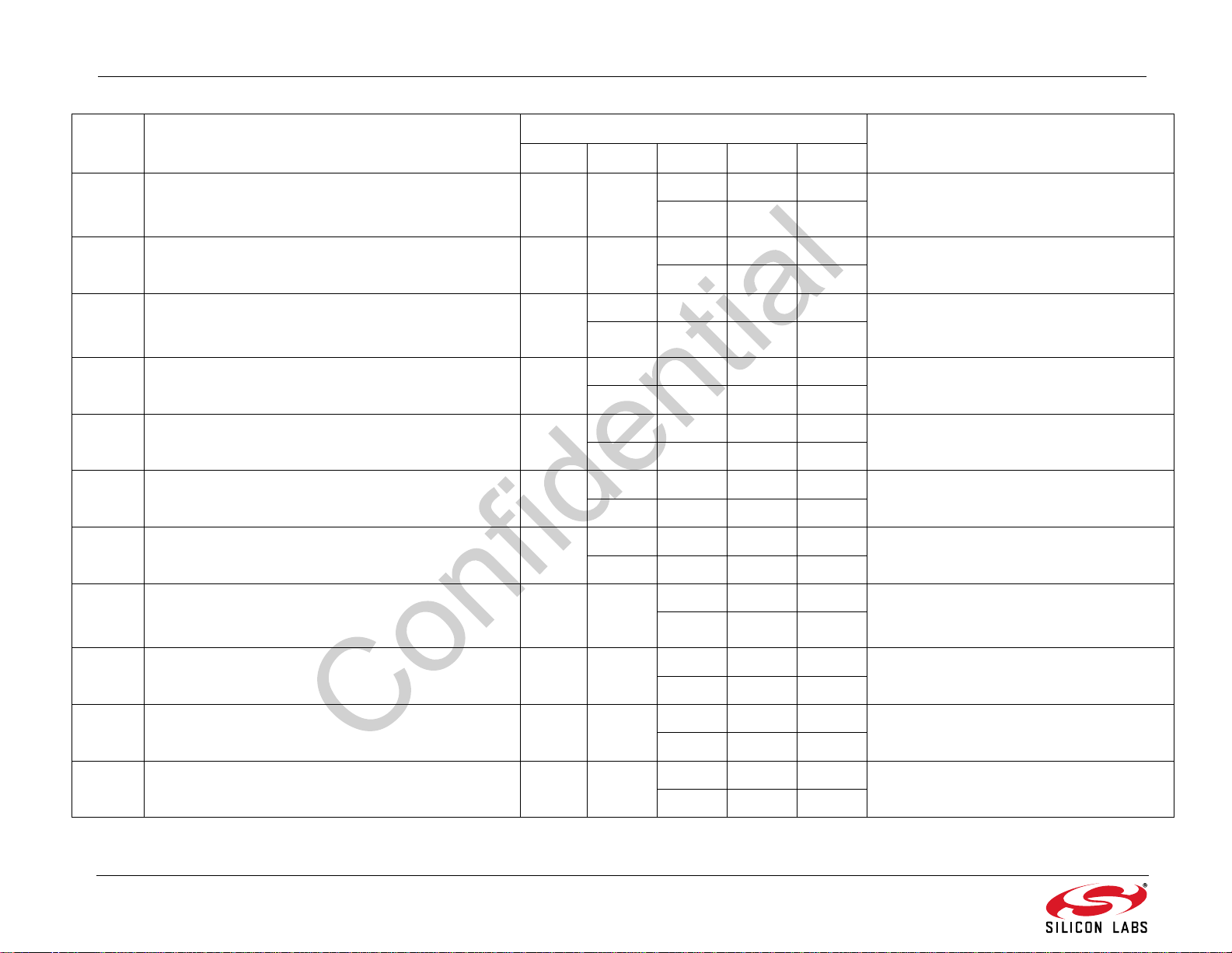
AN543
Table 12. FM Receiver Properties Summary (Continued)
Address Name Default Summary
A10 A20 A30 A40 A55
0x2210 FM_CHBW_BLOCKER_THR N/A
0x2214 FM_CHBW_ASSI_B_CONTROL N/A N/A
0x2215 FM_CHBW_STRONGDEV_MIN_MAX N/A
0x2216 FM_CHBW_STRONGDEV_LOW_THRESHOLD N/A
0x2217 FM_CHBW_STRONGDEV_HIGH_THRESHOLD N/A
0x2218 FM_CHBW_STRONGDEV_WIDENING_TIME N/A
0x2219 FM_CHBW_STRONGDEV_NARROWING_TIME N/A
0x221A FM_CHBW_ASSI200DEV_MIN_MAX N/A N/A
Do not
Write
0x9680 0x9680 0x9680 0x9664
38528 38528 38528 38500
0x0008 0x0008 0x0008 0x0008
8888
0x0013 0x0013 0x0013 0x0013
19 19 19 19
0x1000 0x1000 0x1000 0x1000
4096 4096 4096 4096
0x0200 0x0200 0x0200 0x0200
512 512 512 512
0x140A 0x140A 0x140A
5130 5130 5130
0x0000 0x0200 0x0200
0 512 512
0x5020 0x9646 0x9646
20512 38470 38470
Sets the threshold and hysteresis to enable
channel filter bandwidth based on
ASSI200DEV.
Selects the behavior of ASSI-B channel filter bandwidth control engine.
Sets the maximum and minimum channel
filter bandwidth in units of kHz based on
STRONGDEV.
Sets the STRONGDEV threshold for maximum channel filter bandwidth.
Sets the STRONGDEV threshold for minimum channel filter bandwidth.
Sets the channel filter bandwidth widening
time based on STRONGDEV.
Sets the channel filter bandwidth narrowing
time based on STRONGDEV.
Sets the maximum and minimum channel
filter bandwidth in units of kHz based on
ASSI200DEV.
0x221B FM_CHBW_ASSI200DEV_LOW_THRESHOLD N/A N/A
0x221C FM_CHBW_ASSI200DEV_HIGH_THRESHOLD N/A N/A
0x221D FM_CHBW_ASSI200DEV_WIDENING_TIME N/A N/A
46 Rev. 0.9
0x0032 0x0032 0x0032
50 50 50
0x005A 0x005A 0x005A
90 90 90
0x0800 0x0800 0x0800
2048 2048 2048
Sets the ASSI200DEV threshold for maximum channel filter bandwidth.
Sets the ASSI200DEV threshold for minimum channel filter bandwidth.
Sets the channel filter bandwidth widening
time based on ASSI200DEV.
Page 47
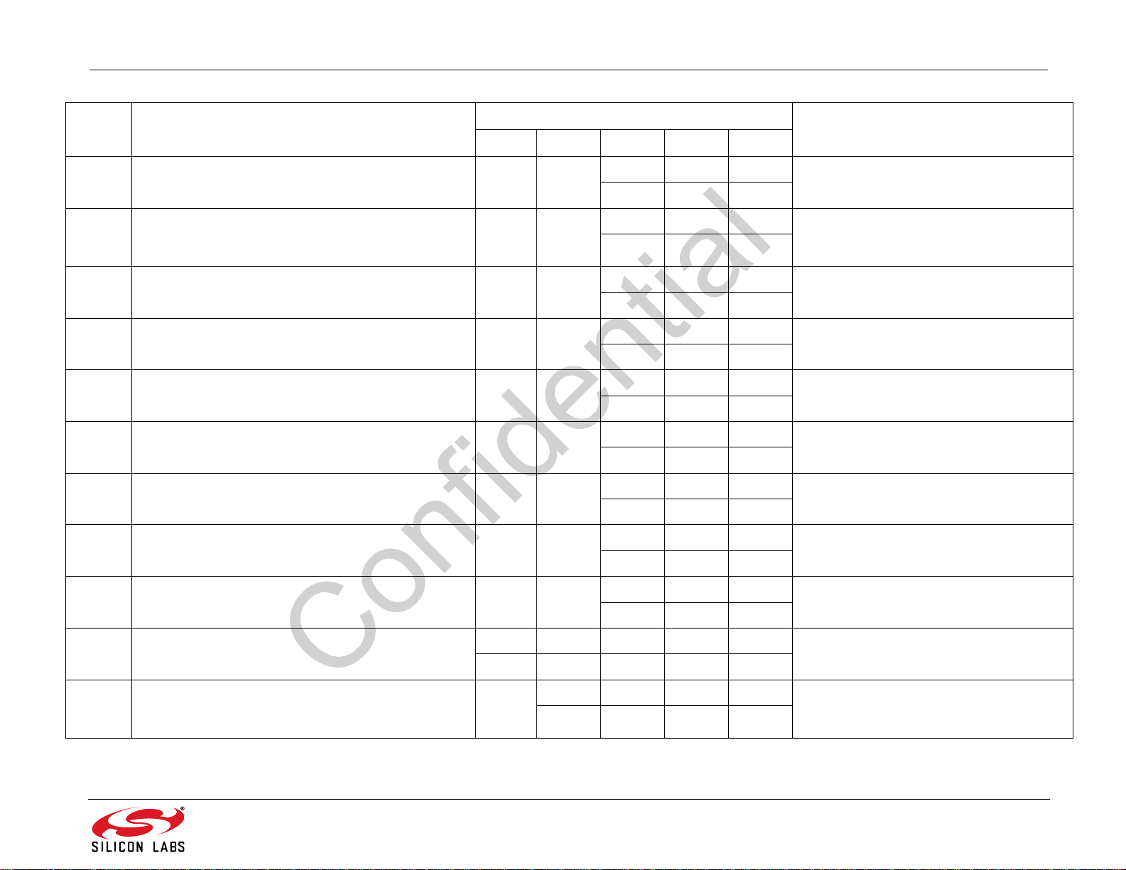
AN543
Table 12. FM Receiver Properties Summary (Continued)
Address Name Default Summary
A10 A20 A30 A40 A55
0x221E FM_CHBW_ASSI200DEV_NARROWING_TIME N/A N/A
0x221F FM_CHBW_ASSI_B_MIN_MAX N/A N/A
0x2220 FM_CHBW_ASSI_B_LOW_THRESHOLD N/A N/A
0x2221 FM_CHBW_ASSI_B_HIGH_THRESHOLD N/A N/A
0x2222 FM_CHBW_ASSI_B_WIDENING_TIME N/A N/A
0x2223 FM_CHBW_ASSI_B_NARROWING_TIME N/A N/A
0x3105 FM_LOWCUT_MIN_FREQ
0x3106 FM_LOWCUT_MAX_FREQ
Do Not
Do Not
Write
Write
N/A
N/A
0x0080 0x0080 0x0080
128 128 128
0x9696 0x9696 0x9696
38550 38550 38550
0x0000 0x0000 0xFFFB
00-5
0x0000 0x0000 0x0005
005
0x0001 0x0001 0x0FA0
1 1 4000
0x0001 0x0001 0x0190
1 1 400
0x0000 0x0000 0x0000
000
0x0000 0x0000 0x0000
000
Sets the channel filter bandwidth narrowing
time based on ASSI200DEV.
Sets the maximum and minimum channel
filter bandwidth in units of kHz based on
max (HASSI,LASSI).
Sets the max (HASSI,LASSI) threshold for
maximum channel filter bandwidth.
Sets the max (HASSI,LASSI) threshold for
minimum channel filter bandwidth.
Sets the channel filter bandwidth widening
time based on max (HASSI,LASSI).
Sets the channel filter bandwidth narrowing
time based on max (HASSI,LASSI).
Sets the minimum LowCut cutoff frequency.
Sets the maximum LowCut cutoff frequency.
0x3200 FM_POP_NOISE_FADE_HYST
0x3207 FM_POP_NOISE_MODE
0x3208 FM_POP_NOISE_RSSI_THRESHOLDS N/A
Do not
Write
0x0001 0x0001 0x0001 0x0001 0x0002
11112
Do not
Write
0xECE7 0xECE7 0xECE7 0xFDF9
60647 60647 60647 65017
Rev. 0.9 47
0x0A06 0x0A06 0x0604
2566 2566 1540
Sets the thresholds for FM pop filter fading
hysteresis
Sets the pop mitigation mode.
Sets the change in RSSI thresholds for
maximum and minimum MPX limiting (set
by property 0x3209).
Page 48
AN543
Table 12. FM Receiver Properties Summary (Continued)
Address Name Default Summary
A10 A20 A30 A40 A55
0x3209 FM_POP_NOISE_RSSI_MPX_LIMIT N/A
0x320A FM_POP_NOISE_RSSI_MPX_ATTACK N/A
0x320B FM_POP_NOISE_RSSI_MPX_RELEASE N/A
0x320C FM_POP_NOISE_MPX_USN_THRESHOLDS N/A
0x320D FM_POP_NOISE_MPX_USN_LIMITS N/A
0x320E FM_POP_NOISE_MPX_USN_ATTACK N/A
0x320F FM_POP_NOISE_MPX_USN_RELEASE N/A
0x007F 0x007F 0x007F 0x007F 0x007F
0x3210 FM_POP_NOISE_SCALE
127 127 127 127 127
0x1009 0x1009 0x1009 0x0502
4105 4105 4105 1282
0x0001 0x0001 0x0001 0x001E
11130
0x0001 0x0001 0x0001 0x0BB8
1 1 1 3000
0x03FE 0x03FE 0x03FE 0x0501
1022 1022 1022 1281
0x1009 0x1009 0x1009 0x0502
4105 4105 4105 1282
0x0001 0x0001 0x0001 0x001E
11130
0x0001 0x0001 0x0001 0x0BB8
1 1 1 3000
Sets the minimum and maximum limit for
MPX limiter based on change in RSSI.
Sets the attack rate for MPX limiter pop mitigation.
Sets the release rate for pop mitigation.
Sets the ratio of MPX to USN thresholds for
maximum and minimum MPX limiting (set
by property 0x320D).
Sets the maximum and minimum limit for
MPX limiter based on ratio of MPX to USN.
Sets the attack rate for MPX limiter pop mitigation.
Sets the release rate for pop mitigation.
Sets the scale for the FM pop filter.
0x3400 FM_MULT_EQ_CTL N/A N/A
0x3401 FM_MULT_EQ_NOISE_DISABLE N/A N/A
0x3402 FM_MULT_EQ_CTL_STEP N/A N/A
0x3409
48 Rev. 0.9
FM_EQ_CTL_AUTOTAP N/A N/A N/A N/A
0x0601 0x0601 0x8001
1537 1537 32769
0xFC81 0xFCFA 0xFCFA Sets the RSSI threshold below which the
64641 64762 64762
0x0000 0x0000 0x0000
000
0x03FB
1019
Controls the multipath channel equalizer.
channel equalizer will use noise measurement to enable/disable channel equalizer.
Sets the channel
rate.
Sets the threshold for channel equalizer
auto tap control.
equalizer tap updating
Page 49
AN543
Table 12. FM Receiver Properties Summary (Continued)
Address Name Default Summary
A10 A20 A30 A40 A55
0x3500 FM_BLEND_RSSI_THRESHOLDS
0x3501 FM_BLEND_RSSI_STEREO_SEP
0x3502 FM_BLEND_RSSI_ATTACK_TIME
0x3503 FM_BLEND_RSSI_RELEASE_TIME
0x3508 FM_BLEND_MULTIPATH_THRESHOLDS
0x3509 FM_BLEND_MULTIPATH_STEREO_SEP
0x350A F M _BLEND_MU LT I PAT H _ATTACK_TIME
0x350B FM_BLEND_MULTIPATH_RELEASE_TIME
0x3719 0x3719 0x3719 0x3719 0x3719
14105 14105 14105 14105 14105
0x2D00 0x2D00 0x2D00 0x2D00 0x2D00
11520 11520 11520 11520 11520
0x0010 0x0010 0x0010 0x0010 0x0010
16 16 16 16 16
0x0FA0 0x0FA0 0xFA0 0xFA0 0xFA0
4000 4000 4000 4000 4000
0x1E3C 0x1E3C 0x1E3C 0x1E3C 0x0A14
7740 7740 7740 7740 2580
0x2D00 0x2D00 0x2D00 0x2D00 0x2D00
11520 11520 11520 11520 11520
0x0010 0x0010 0x0010 0x0010 0x0010
16 16 16 16 16
0x0FA0 0x0FA0 0x0FA0 0x0FA0 0x0FA0
4000 4000 4000 4000 4000
Sets the thresholds for the RSSI metric for
the stereo blend mitigation engine.
Set the limits for the stereo separation
when driven by RSSI on the stereo blend
mitigation engine.
Sets the stereo blend attack time in ms.
Sets the stereo blend release time in ms.
Sets the thresholds for the multipath metric
for the stereo blend mitigation engine.
Sets the limits for the stereo separation
when driven by multipath on the stereo
blend mitigation engine.
Sets the stereo blend attack time in ms.
Sets the stereo blend release time in ms.
0x3510 FM_BLEND_USN_THRESHOLDS
0x3511 FM_BLEND_USN_STEREO_SEP
0x3512 FM_BLEND_USN_ATTACK_TIME
0x341B 0x341B 0x341B 0x341B 0x341B
13339 13339 13339 13339 13339
0x2D00 0x2D00 0x2D00 0x2D00 0x2D00
11520 11520 11520 11520 11520
0x0010 0x0010 0x0010 0x0010 0x0010
16 16 16 16 16
Rev. 0.9 49
Set the thresholds for the USN metric for
the stereo blend mitigation engine.
Sets the limits for the stereo separation
when driven by USN on the stereo blend
mitigation engine.
Sets the stereo blend attack time in ms.
Page 50
AN543
Table 12. FM Receiver Properties Summary (Continued)
Address Name Default Summary
A10 A20 A30 A40 A55
0x3513 FM_BLEND_USN_RELEASE_TIME
0x3518 FM_BLEND_CHBW_LIMITS
0x3519 FM_BLEND_CHBW_STEREO_SEP
0x351A FM_BLEND_CHBW_ATTACK_TIME
0x351B FM_BLEND_CHBW
0x3600 FM_HICUT_RSSI_THRESHOLDS
0x3601 FM_HICUT_RSSI_CUTOFF_FREQ
0x3602 FM_HICUT_RSSI_ATTACK_TIME
0x3603 FM_HICUT_RSSI_RELEASE_TIME
0x0FA0 0x0FA0 0x0FA0 0x0FA0 0x0FA0
4000 4000 4000 4000 4000
0x0000 0X0000 0x0000 0x0000 0x0000
00000
0x2D2D 0x2D2D 0x2D2D 0x2D2D 0x2D2D Set the limits for the stereo separation
11565 11565 11565 11565 11565
0x0001 0x0001 0x0001 0x0001 0x0001
11111
0x0001 0x0001 0x0001 0x0001 0x0001
11111
0x230F 0x230F 0x230F 0x230F 0x230F
8975 8975 8975 8975 8975
0xB428 0xB428 0xB428 0xB428 0xB419
46120 46120 46120 46120 46105
0x0010 0x0010 0x0010 0x0010 0x0064
16 16 16 16 100
0x0FA0 0x0FA0 0x0FA0 0x0FA0 0x0FA0
4000 4000 4000 4000 4000
Sets the stereo blend release time in ms.
Set the limits for CHBW input metric on the
stereo blend mitigation engine
when driven by CHBW on the stereo blend
mitigation engine
Set stereo blend attack time in ms
Set stereo blend release time in ms
Sets the thresholds for the RSSI metric for
the L+R high cut mitigation engine.
Sets the limits for the cutoff frequency when
driven by RSSI on the L+R high cut mitigation engine.
Sets the L+R high cut attack time in ms.
Sets the L+R high cut release time in ms.
0x3608 FM_HICUT_MULTIPATH_THRESHOLDS
0x3250 0x3250 0x3250 0x3250 0x0A14
12880 12880 12880 12880 2580
0xB428 0xB428 0xB428 0xB428 0x6419
0x3609 FM_HICUT_MULTIPATH_CUTOFF_FREQ
46120 46120 46120 46120 25625
0x0010 0x0010 0x0010 0x0010 0x0064
0x360A FM_HICUT_MULTIPATH_ATTACK_TIME
16 16 16 16 100
50 Rev. 0.9
Sets the thresholds for the multipath metric
for the L+R high cut mitigation engine.
Set the limits for the cutoff frequency when
driven by multipath on the L+R high cut mitigation engine.
Sets the L+R high cut attack time in ms.
Page 51
AN543
Table 12. FM Receiver Properties Summary (Continued)
Address Name Default Summary
A10 A20 A30 A40 A55
0x360B FM_HICUT_MULTIPATH_RELEASE_TIME
0x3610 FM_HICUT_USN_THRESHOLDS
0x3611 FM_HICUT_USN_CUTOFF_FREQ
0x3612 FM_HICUT_USN_ATTACK_TIME
0x3613 FM_HICUT_USN_RELEASE_TIME
0x3618 FM_HICUTN_CHBW_LIMITS
0x3619 FM_HICUTN_CHBW_CUTOFF_FREQ
0x361A FM_HICUTN_CHBW_ATTACK_TIME
0x361B HM_HICUTN_CHBW_RELEASE_TIME
0x3700 FM_HIBLEND_RSSI_THRESHOLDS
0x0FA0 0x0FA0 0x0FA0 0x0FA0 0x0FA0
4000 4000 4000 4000 4000
0x250F 0x250F 0x250F 0x250F 0x250F
9487 9487 9487 9487 9487
0xB428 0xB428 0xB428 0xB428 0xB419
46120 46120 46120 46120 46105
0x0010 0x0010 0x0010 0x0010 0x0064
16 16 16 16 100
0x0FA0 0x0FA0 0x0FA0 0x0FA0 0x0FA0
4000 4000 4000 4000 4000
0x0000 0x0000 0x0000 0x0000 0x0000
00000
0xB4B4 0xB4B4 0xB4B4 0xB4B4 0xB4B4 Set the limits for the cutoff frequency when
46260 46260 46260 46260 46260
0x0001 0x0001 0x0001 0x0001 0x0001
11111
0x0001 0x0001 0x0001 0x0001 0x0001
11111
0x371B 0x371B 0x371B 0x371B 0x371B
14107 14107 14107 14107 14107
Sets the L+R high cut release time in ms.
Sets the thresholds for the USN metric for
the L+R high cut mitigation engine.
Sets the limits for the cutoff frequency when
driven by USN on the L+R high cut mitigation engine.
Sets the L+R high cut attack time in ms.
Sets the L+R high cut release time in ms.
Set the limits for the CHBW input metric on
L+R high cut mitigation engine
driven by CHBW on the L+R high cut mitigation engine
Set L+R high cut attack time in ms
Set L+R high cut release time in ms
Sets the thresholds for the RSSI metric for
the L–R high cut mitigation engine.
0x3701 FM_HIBLEND_RSSI_CUTOFF_FREQ
0x3702 FM_HIBLEND_RSSI_ATTACK_TIME
0xB41E 0xB41E 0xB41E 0xB41E 0xB419
46110 46110 46110 46110 46105
0x0004 0x0004 0x0004 0x0004 0x0064
4444100
Rev. 0.9 51
Sets the limits for the cutoff frequency when
driven by RSSI on the L–R high-blend mitigation engine.
Sets the L–R high-blend attack time in ms.
Page 52
AN543
Table 12. FM Receiver Properties Summary (Continued)
Address Name Default Summary
A10 A20 A30 A40 A55
0x3703 FM_HIBLEND_RSSI_RELEASE_TIME
0x3708 FM_HIBLEND_MULTIPATH_THRESHOLDS
0x3709 FM_HIBLEND_MULTIPATH_CUTOFF_FREQ
0x370A FM_HIBLEND_MULTIPATH_ATTACK_TIME
0x370B FM_HIBLEND_MULTIPATH_RELEASE_TIME
0x3710 FM_HIBLEND_USN_THRESHOLDS
0x3711 FM_HIBLEND_USN_CUTOFF_FREQ
0x3712 FM_HIBLEND_USN_ATTACK_TIME
0x1F40 0x1F40 0x1F40 0x1F40 0x0FA0
8000 8000 8000 8000 4000
0x193C 0x193C 0x193C 0x193C 0x080F
6460 6460 6460 6460 2063
0xB41E 0xB41E 0xB41E 0xB41E 0x6419
46110 46110 46110 46110 25625
0x0004 0x0004 0x0004 0x0004 0x0064
4444100
0x1F40 0x1F40 0x1F40 0x1F40 0x0FA0
8000 8000 8000 8000 4000
0x371E 0x371E 0x371E 0x371E 0x371E
14110 14110 14110 14110 14110
0xB41E 0xB41E 0xB41E 0xB41E 0x9619
46110 46110 46110 46110 38425
0x0004 0x0004 0x0004 0x0004 0x0064
4444100
Sets the L–R high-blend release time in ms.
Sets the thresholds for the multipath metric
for the L–R high-blend mitigation engine.
Sets the limits for the cutoff frequency when
driven by multipath on the L–R high-blend
mitigation engine.
Sets the L–R high-blend attack time in ms.
Sets the L–R high-blend release time in ms.
Sets the thresholds for the USN metric for
the L–R high-blend mitigation engine.
Sets the limits for the cutoff frequency when
driven by USN on the L–R high-blend mitigation engine.
Sets the L–R high-blend attack time in ms.
0x3713 FM_HIBLEND_USN_RELEASE_TIME
0x3718 FM_HIBLEND_CHBW_LIMITS
0x3719 FM_HIBLEND_CHBW_CUTOFF_FREQ
52 Rev. 0.9
0x1F40 0x1F40 0x1F40 0x1F40 0x0FA0
8000 8000 8000 8000 4000
0x0000 0x0000 0x0000 0x0000 0x0000
00000
0xB4B4 0xB4B4 0xB4B4 0xB4B4 0xB4B4 Set the limits for the cutoff frequency when
46260 46260 46260 46260 46260
Sets the L–R high-blend release time in ms.
Set the limits for the CHBW input metric on
the hi-blend (L-R high cut) mitigation
engine.
driven by CHBW on the hi-blend (L-R high
cut) mitigation engine.
Page 53
AN543
Table 12. FM Receiver Properties Summary (Continued)
Address Name Default Summary
A10 A20 A30 A40 A55
0x371A FM_HIBLEND_CHBW_ATTACK_TIME
0x371B FM_HIBLEND_CHBW_RELEASE_TIME
0x4000 FM_RDS_INTERRUPT_SOURCE
0x0001 0x0001 0x0001 0x0001 0x0001
11111
0x0001 0x0001 0x0001 0x0001 0x0001
11111
0x0000 0x0000 0x0000 0x0000 0x0000
00000
Set hi-blend (L-R high cut) attack time in ms
Set hi-blend (L-R high cut) release time in
ms.
Configures interrupt related to RDS.
0x4001 FM_RDS_INTERRUPT_FIFO_COUNT
0x4002 FM_RDS_CONFIG
0x4003 FM_RDS_CONFIDENCE
0x0000 0x0000 0x0000 0x0000 0x0000
00000
0x0000 0x0000 0x0000 0x0000 0x0000
00000
0x1111 0 x 1111 0x1111 0x1111 0x 1111
4369 4369 4369 4369 4369
Sets the minimum number of RDS groups
stored in the RDS FIFO before RDSRECV
is set.
Configures RDS settings to enable RDS
processing (RDSEN) and set RDS block
error thresholds.
Sets the confidence level requirement for
each RDS block.
Rev. 0.9 53
Page 54
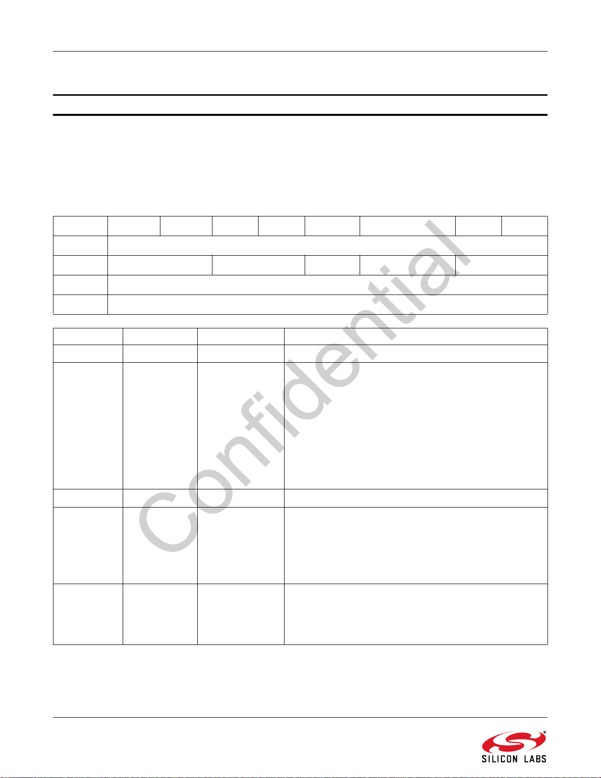
AN543
7.2.1. FM Receiver Commands
Command 0x30 FM_TUNE_FREQ
The FM_TUNE_FREQ command sets the FM Receiver to tune to a frequency between 64 and 108 MHz in 10 kHz
units. The CTS bit (and optional interrupt) is set when it is safe to send the next command. The ERR bit (and
optional interrupt) is set if an invalid argument is sent. Note that only a single interrupt occurs if both the CTS and
ERR bits are set. The optional STC interrupt is set when the command completes. This command may only be sent
in powerup mode. The command clears the STC bit if it is already set.
Command
Bit 7 6 5 4 3 2 1 0
CMD
ARG1
ARG2 FREQH[7:0]
ARG3 FREQL[7:0]
ARG Bit Name Function
17:6Reserved
1 5:4 TUNEMODE[1:0]
13Reserved
12
00 TUNEMODE[1:0] 0
Sets the Desired Tuning Mode.
0 = Validated normal tune: Unconditionally stay on the new
channel after tune, tune status is valid.
1 = Invalidated fast tune: Unconditionally stay on the new
channel after tune, tune status invalid.
2 = Validated AF Tune: Jump back to previous channel if
metric thresholds are not met (Si4755/57 only).
3 = Validated AF Check: Unconditionally jump back to the
previous channel (Si4755/57 only).
Smoothly transition audio state after tune.
0 = Initialize audio state to match this new channel.
SMOOTH-
METRICS
1 = Transition audio state from previous channel values to
the new channel values.
Note: This is the recommended setting when performing an AF
0x30
SMOOTHMETRICS INJSIDE[1:0]
Always write 0.
Always write 0.
check.
Selects Injection Side.
1 1:0 INJSIDE[1:0]
54 Rev. 0.9
0 = Automatic injection side selection by the tuner.
1 = Force low-side injection.
2 = Force high-side injection.
Page 55
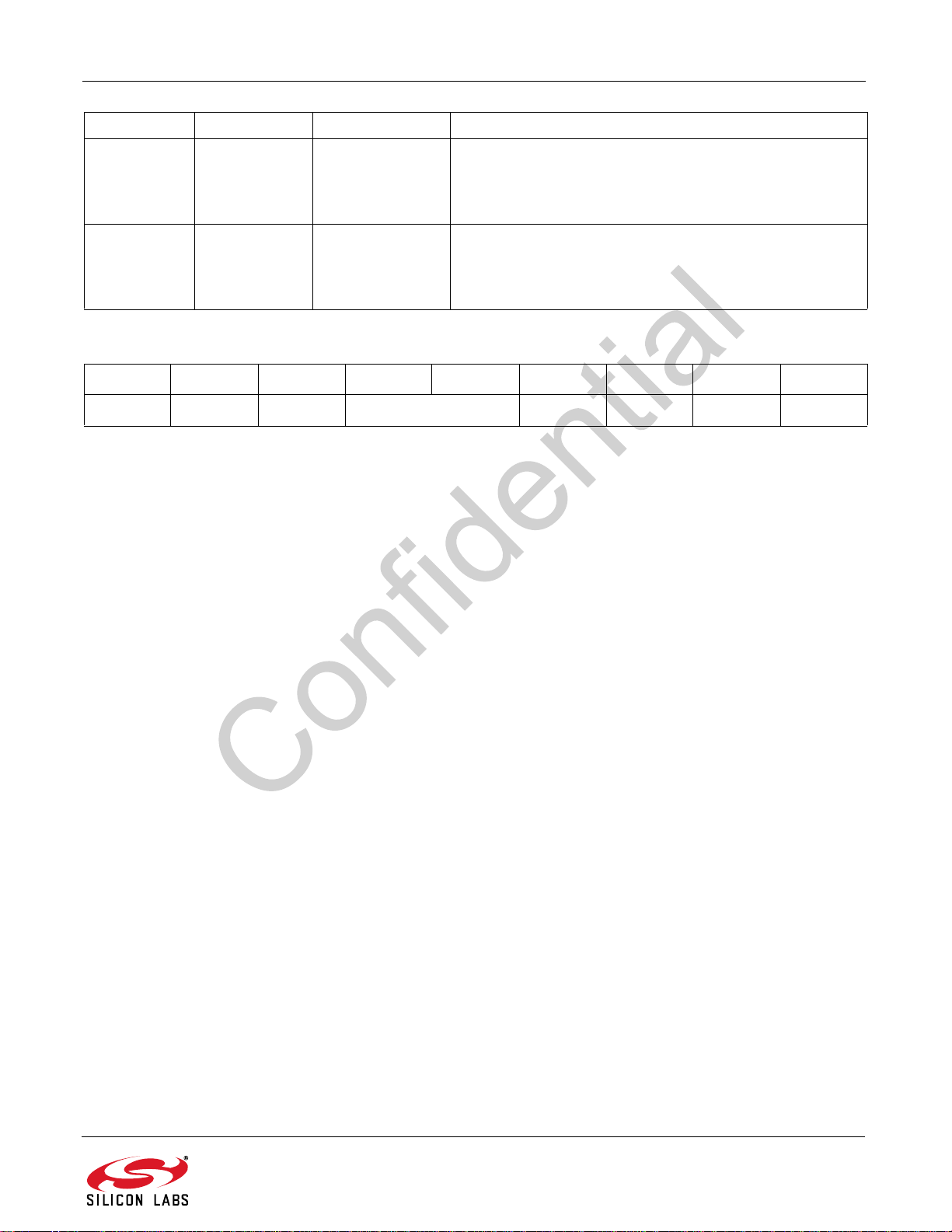
AN543
ARG Bit Name Function
Tune Frequency High Byte.
27:0FREQ
37:0FREQ
Response
Bit76543210
H
L
[7:0]
[7:0]
This byte in combination with FREQL selects the tune
frequency in units of 10 kHz. In FM mode the valid range is
from 6400 to 10800 (64–108 MHz).
Tune Frequency Low Byte.
This byte in combination with FREQH selects the tune
frequency in units of 10 kHz. In FM mode, the valid range is
from 6400 to 10800 (64–108 MHz).
STATUS
CTS ERR XX RSQINT RDSINT ACFINT STCINT
Rev. 0.9 55
Page 56
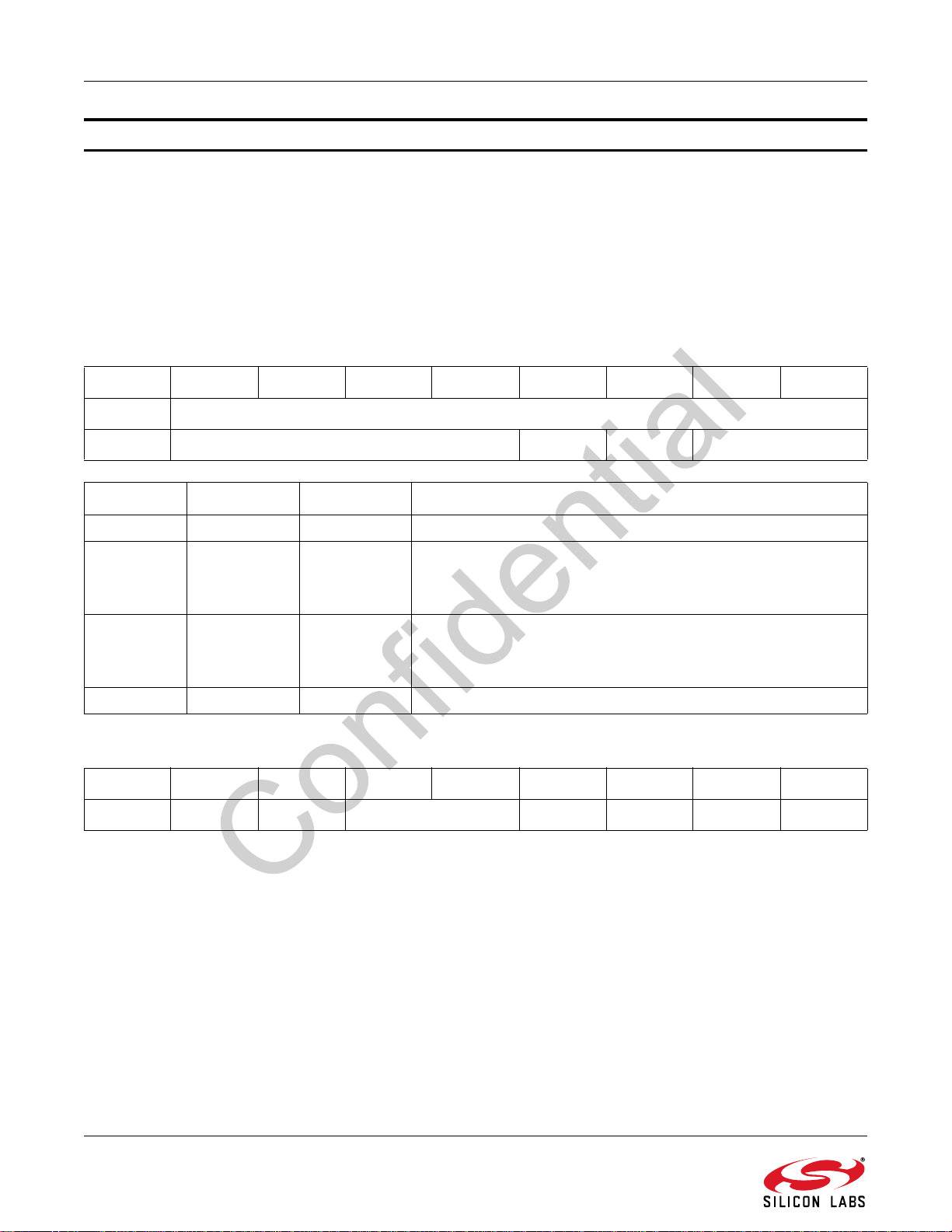
AN543
Command 0x31 FM_SEEK_START
The FM_SEEK_START command begins searching for a valid station. In order for a station to be considered valid,
each of the following thresholds must be met:
FM_VALID_ASSI_THRESHOLD, FM_VALID_ISSI_THRESHOLD, and FM_VALID_MAX_TUNE_ERROR. Clears
any pending STCINT, RSQINT, or RDSINT interrupt status. Seek can be cancelled through setting the CANCEL bit
in the FM_RSQ_STATUS command. The CTS bit (and optional interrupt) is set when it is safe to send the next
command. The ERR bit (and optional interrupt) is set if an invalid argument is sent. Note that only a single interrupt
occurs if both the CTS and ERR bits are set. The optional STC interrupt is set when the command completes. This
command may only be sent in powerup mode. The command clears the STCINT bit if it is already set.
Command
Bit76543210
FM_VALID_SNR_THRESHOLD, FM_VALID_RSSI_THRESHOLD,
CMD
ARG1 0000 SEEKUP WRAP 00
ARG Bit Name Function
1 7:4 Reserved Always write 0000.
Seek Up/Down.
1 3 SEEKUP
12WRAP
1 1:0 Reserved Always write 00.
Response
Bit76543210
STATUS
CTS ERR XX RSQINT RDSINT ACFINT STCINT
Determines the direction of the search, either UP = 1, or
DOWN = 0.
Wrap/Halt.
Determines whether the seek should Wrap = 1, or Halt = 0 when
it hits the band limit.
0x31
56 Rev. 0.9
Page 57
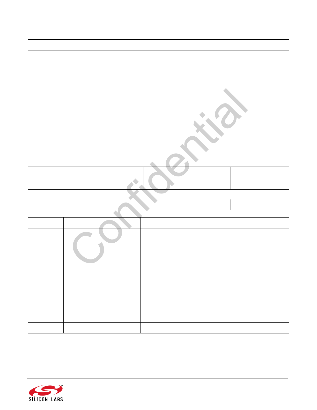
AN543
Command 0x32 FM_RSQ_STATUS
The FM_RSQ_STATUS command returns status information about the received signal quality. This command
returns the Received Signal Strength Indicator (RSSI), Signal to Noise Ratio (SNR), Adjacent Channel Strength for
200 kHz (ASSI200), Adjacent Channel Strength for 100 kHz (LASSI and HASSI), frequency offset (FREQOFF),
Multipath (MULT), Ultrasonic Noise (USN), Pilot Deviation (PILOTDEV), RDS Deviation (RDSDEV), Adjacent
Channel Deviation for 200 kHz (ASSI200DEV), Deviation (DEV and STRONGDEV), and RDS PI code (RDSPI)
associated with the desired channel. It also indicates valid channel (VALID) and AFC rail status (AFCRL). This
command can be used to check if the received signal is above the RSSI high threshold as reported by RSSIHINT
or below the RSSI low threshold as reported by RSSILINT. It can also be used to check if the signal is above the
SNR high threshold as reported by SNRHINT or below the SNR low threshold as reported by SNRLINT. It can be
used to check if the detected multipath is above the Multipath high threshold as reported by MULTHINT or below
the Multipath low threshold as reported by MULTLINT.
The command clears the RSQINT, SNRHINT, SNRLINT, RSSIHINT, RSSILINT, MULTHINT, and MULTLINT
interrupt bits when the RSQACK bit of ARG1 is set. If the condition is still true after the interrupt is cleared, another
interrupt will fire assuming that bit is enabled in FM_RSQ_INTERRUPT_SOURCE. The CTS bit (and optional
interrupt) is set when it is safe to send the next command. This command may only be sent when in powerup
mode.
FM_RSQ_
STATUS
Command
CMD
ARG1
ARG Bit Name Function
1 7:4 Reserved Always write 0000.
1 3 RSQACK
1 2 ATTUNE
1 1 CANCEL
76543210
0x32
0000 RSQACK ATTUNE CANCEL STCACK
Clears RSQINT, SNRHINT, SNRLINT, RSSIHINT, RSSILINT,
MULTHINT, and MULTLINT if set.
Returns the values of metrics as of tune time. When the
ATTUNE bit is set, values returned for RSQ_STATUS are the
values calculated at tune and do not change unless another
FM_TUNE_FREQ or FM_SEEK_START command is called.
This feature can be used to determine why seek stopped at the
current station.
Aborts a seek or tune currently in progress.
0 = Don't abort.
1 = Abort.
1 0 STCACK Clears the STC interrupt status indicator if set.
Rev. 0.9 57
Page 58

AN543
Response
Bit 7 6 5 4 3 2 1 0
STATUS
RESP1 MULTHINT MULTLINT ISSIHINT ISSILINT SNRHINT SNRLINT RSSIHINT RSSILINT
RESP 2 BLTF X SNRREADY RSSIREADY X INJSIDE AFCRL VALID
RESP 3 READFREQ[15:8]
RESP 4 READFREQ[7:0]
RESP 5 FREQOFF[7:0]
RESP 6 RSSI[7:0]
RESP 7 SNR[7:0]
RESP 8 ISSI[7:0]
RESP 9 LASSI[7:0]
RESP 10 HASSI[7:0]
RESP 11 MULT[7:0]
RESP 12 DEV[7:0]
RESP 13 XXXXXXXX
CTS ERR XX RSQINT RDSINT ACFINT STCINT
RESP 14 XXXXXXXX
RESP 15 ASSI200[7:0]
RESP 16 USN[7:0]
RESP 17 PILOTDEV[7:0]
RESP 18 RDSDEV[7:0]
RESP 19 ASSI200DEV[7:0]
RESP 20 STRONGDEV[7:0]
RESP 21 RDSPI[15:8]
RESP 22 RDSPI[7:0]
58 Rev. 0.9
Page 59

RESP Bit Name Function
AN543
17MULTHINT
16MULTLINT
1 5 ISSIHINT
14ISSILINT
1 3 SNRHINT
Multipath Detect High.
0 = Indicates that multipath value has not exceeded the
Multipath high threshold set by
FM_RSQ_MULTIPATH_HIGH_THRESHOLD.
1 = Indicates that multipath value has exceeded the
Multipath high threshold set by
FM_RSQ_MULTIPATH_HIGH_THRESHOLD.
Multipath Detect Low.
0 = Indicates that multipath value has not fallen below the
Multipath low threshold set by
FM_RSQ_MULTIPATH_LOW_THRESHOLD.
1 = Indicates that multipath value has fallen below the
Multipath low threshold set by
FM_RSQ_MULTIPATH_LOW_THRESHOLD.
ISSI Detect High.
(Available in Si475x-A30 only)
0 = Indicates that ISSI has not exceeded the ISSI high
threshold set by
FM_RSQ_ISSI_HIGH_THRESHOLD.
1 = Indicates that ISSI has exceeded the ISSI high
threshold set by
FM_RSQ_ISSI_HIGH_THRESHOLD.
ISSI Detect Low.
(Available in Si475x-A30 only)
0 = Indicates that ISSI has not fallen below the ISSI low
threshold set by
FM_RSQ_ISSI_LOW_THRESHOLD.
1 = Indicates that ISSI has fallen below the ISSI low
threshold set by
FM_RSQ_ISSI_LOW_THRESHOLD.
SNR Detect High.
0 = Indicates that the received signal SNR has not
exceeded the SNR high threshold set by
FM_RSQ_SNR_HIGH_THRESHOLD
1 = Indicates that the received signal SNR has exceeded
the SNR high threshold set by
FM_RSQ_SNR_HIGH_THRESHOLD.
1 2 SNRLINT
SNR Detect Low.
0 = Indicates that the received signal SNR has not fallen
below the SNR low threshold set by
FM_RSQ_SNR_LOW_THRESHOLD.
1 = Indicates that the received signal SNR has fallen
below the SNR low threshold set by
FM_RSQ_SNR_LOW_THRESHOLD.
Rev. 0.9 59
Page 60

AN543
RESP Bit Name Function
1 1 RSSIHINT
1 0 RSSILINT
27
26
2 5 SNRREADY
2 4 RSSIREADY
BLTF
Reserved Values may vary.
RSSI Detect High.
0 = Indicates that the received signal RSSI has not
exceeded the RSSI high threshold set by
FM_RSQ_RSSI_HIGH_THRESHOLD.
1 = Indicates that the received signal RSSI has exceeded
the RSSI high threshold set by
FM_RSQ_RSSI_HIGH_THRESHOLD.
RSSI Detect Low.
0 = Indicates that the received signal RSSI has not fallen
below the RSSI low threshold set by
FM_RSQ_RSSI_LOW_THRESHOLD.
1 = Indicates that the received signal RSSI has fallen
below the RSSI low threshold set by
FM_RSQ_RSSI_LOW_THRESHOLD.
Band Limit.
Reports if a seek hits the band limit (WRAP = 0 in
FM_START_SEEK) or wrapped to the original frequency
(WRAP = 1).
The SNRREADY and RSSIREADY bits indicate that the
RSSI/SNR have been read as a result of a tune command.
If either one of these bits are 0 this indicates that either the
metric is being measured (because a tune is in progress)
or that the metric was not measured during tune because
the station was invalidated before the metric could be
measured. In the case where a metric was not measured
during tune, the tune time RSQ status will read back as 0
for the unmeasured metric. The normal running time status for these metrics is not affected and will report normally.
0 = SNR measurement in progress (tune in progress) or
not taken (tune completed).
1 = SNR measurement ready.
The SNRREADY and RSSIREADY bits indicate that the
RSSI/SNR have been read as a result of a tune command.
If either one of these bits are 0 this indicates that either the
metric is being measured (because a tune is in progress)
or that the metric was not measured during tune because
the station was invalidated before the metric could be
measured. In the case where a metric was not measured
during tune, the tune time RSQ status will read back as 0
for the unmeasured metric. The normal running time status for these metrics is not affected and will report normally.
0 = RSSI measurement in progress (tune in progress) or
not taken (tune completed).
1 = RSSI measurement ready.
60 Rev. 0.9
Page 61
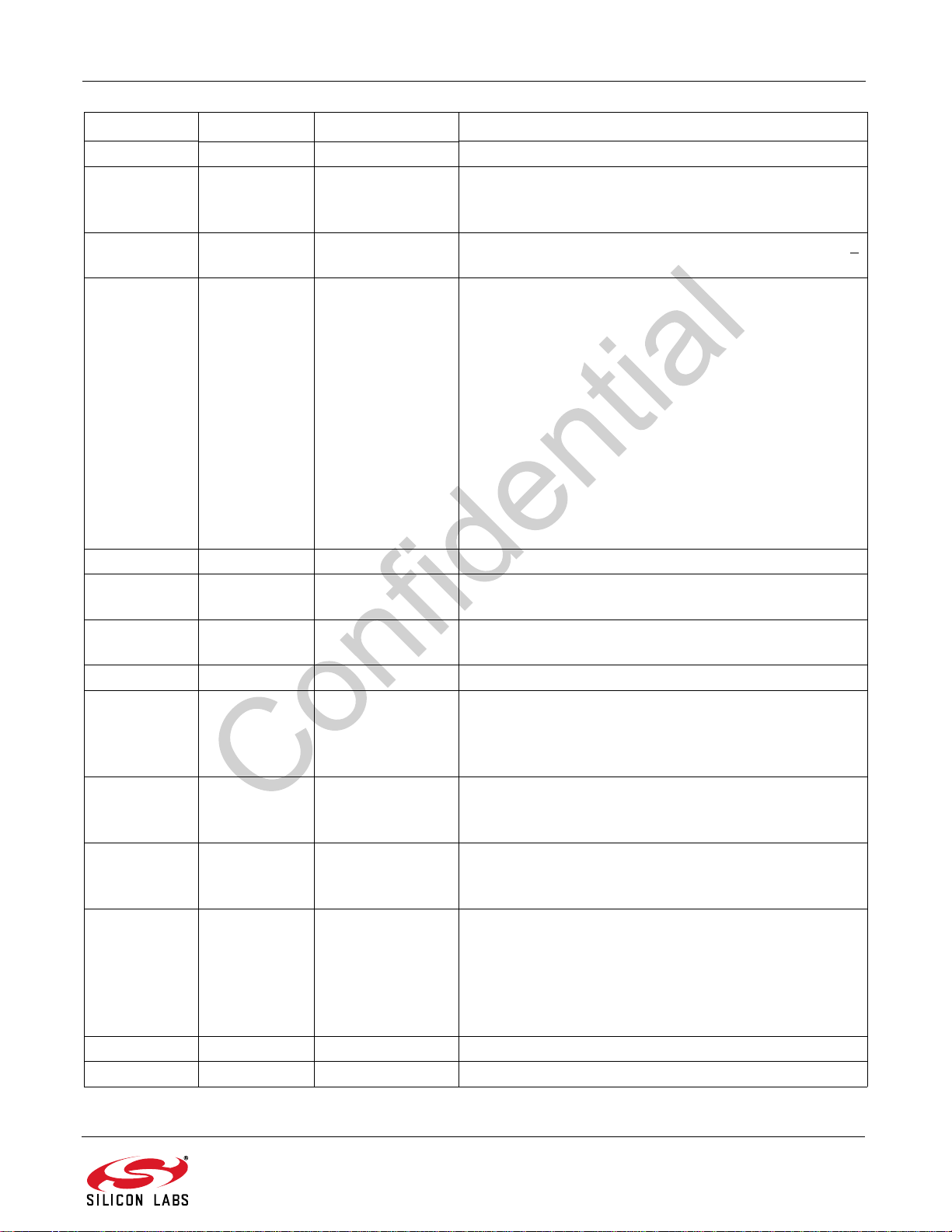
AN543
RESP Bit Name Function
2 3 Reserved Values may vary.
2 2 INJSIDE Injection side used.
0 = Low-side injection is being used
1 = High-side injection is being used
2 1 AFCRL Set if the AFC rails. AFC gets railed if FREQOFF >
FM_VALID_MAX_TUNE_ERROR.
2 0 VALID (Si475x-A20 and earlier)
Reports if the channel is valid based on the settings of:
FM_VALID_RSSI_THRESHOLD,
FM_VALID_SNR_THRESHOLD,
FM_VALID_MAX_TUNE_ERROR
(Si475x-A30 and later)
Reports if the channel is valid based on the settings of:
FM_VALID_RSSI_THRESHOLD,
FM_VALID_SNR_THRESHOLD,
FM_VALID_MAX_TUNE_ERROR,
FM_VALID_ASSI_THRESHOLD,
FM_VALID_ISSI_THRESHOLD
3,4 15:0 READFREQ[15:0] Returns the currently tuned frequency.
5 7:0 FREQOFF[7:0] Signed frequency offset in units set by
FM_VALID_FREQOFF_SCALE (–128 to 126)
6 7:0 RSSI[7:0] Received Signal Strength indicator in dBµV
(–128 to 127)
7 7:0 SNR[7:0] RF SNR indicator in dB (–128 to 127).
8 7:0 ISSI[7:0] Image Signal Strength Indicator reports the image power
relative to carrier (–128 to 127). This metric is only valid
when ATTUNE = 1.
Only applicable to Si475x-A30 and later.
9 7:0 LASSI[7:0] Low side Adjacent (100 kHz) Channel Strength Indicator
reports the (Signal + Noise) power relative to the
carrier.(–128 to 127)
10 7:0 HASSI[7:0] High side Adjacent (100 kHz) Channel Strength Indicator
reports the (Signal + Noise) power relative to the
carrier.(–128 to 127)
11 7:0 MULT[7:0] Multipath Indicator.
(For Si475x-A20 and later)
Range: 0–100%
(ForSi475x-A10)
Multipath = MULT/127 x 100%
Range: 0–127
12 7:0 DEV[7:0] Frequency Deviation metric in kHz.
13, 14 15:0 Reserved Values may vary.
Rev. 0.9 61
Page 62
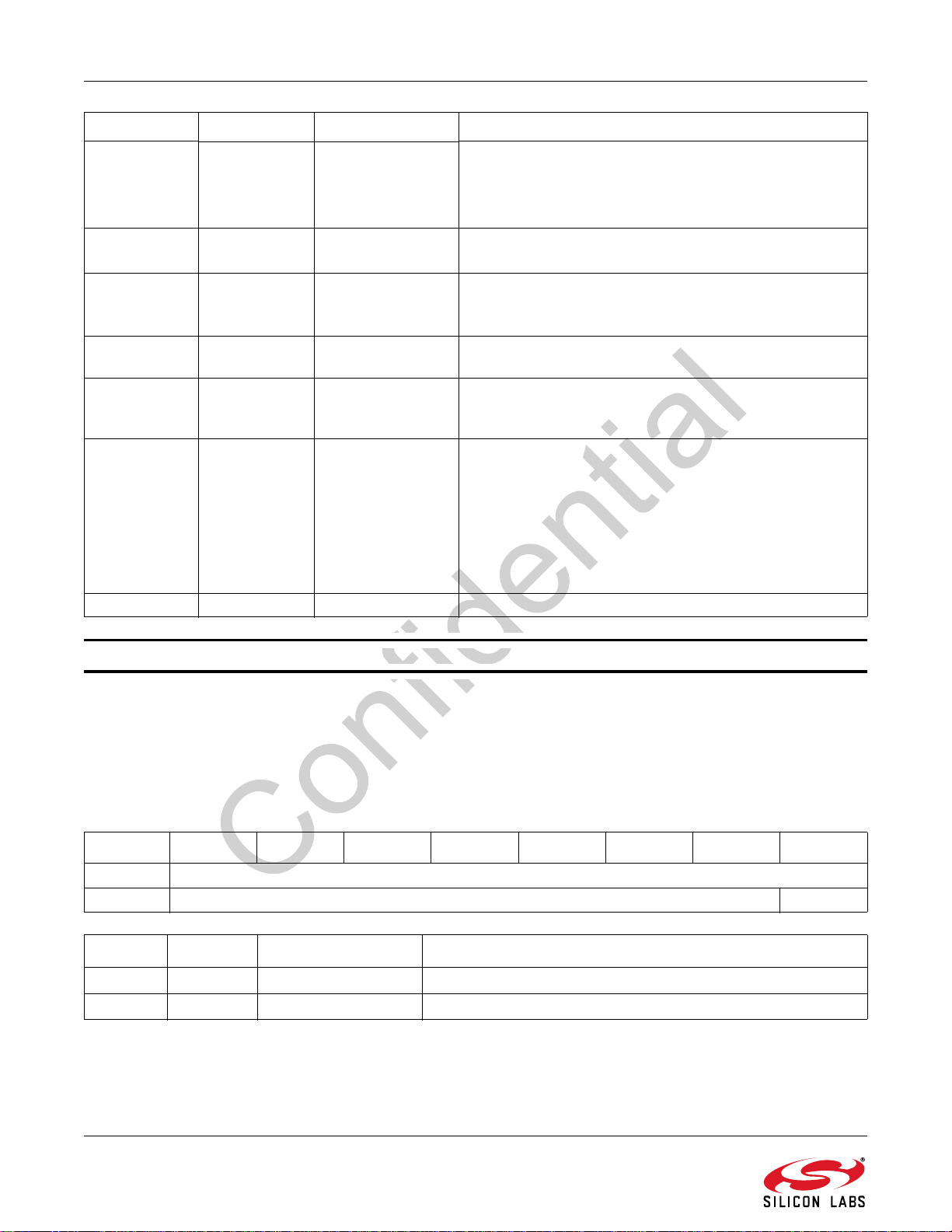
AN543
RESP Bit Name Function
15 7:0 ASSI200[7:0] Adjacent Channel (±200 kHz) Strength Indicator reports
the (Signal + Noise) power relative to the carrier. This
metric reports the sum of high and low adjacent channel
strengths. (–128 to 127)
16 7:0 USN[7:0] Ultrasonic Noise Indicator in –dBFS (0 to 127). 127
corresponds to 127 dB down from full scale.
(Only applicable to Si475x-A30 and later) Pilot deviation in
17 7:0 PILOTDEV[7:0]
18 7:0 RDSDEV[7:0]
19 7:0 ASSI200DEV[7:0]
20 7:0 STRONGDEV[7:0]
21,22 15:0 RDSPI[15:0] (Only applicable to Si475x-A30 and later) RDS PI code.
units of 100 Hz.
Range:0-127
(Only applicable to Si475x-A30 and later) RDS deviation
in units of 100 Hz.
(Only applicable to Si475x-A30 and later) Adjacent
Channel (±200 kHz) Deviation. Deviation is equal to
ASSI200DEV x 1.5 kHz minus 12 kHz.
(Only applicable to Si475x-A30 and later) Deviation of
very strong desired signals. This is an alternative to DEV,
which can become erroneous in the presence of very
strong signals. STRONGDEV is the weighted sum of FM
mono/stereo (L + R) and stereo (L – R) deviation.
Approximately, deviation in kHz = STRONGDEV x f(mod),
where f(mod) is 5.55 kHz for mono signals, or 2.75 kHz for
stereo signals.
Command 0x35 FM_ACF_STATUS
The FM_ACF_STATUS command returns status information about automatically-controlled features. This
command returns the Soft Mute Attenuation, Channel Filter Bandwidth, HICUT cutoff frequency, HIBLEND cutoff
frequency, and Stereo Separation associated with the desired channel. Stereo Separation will only be non-zero if
the pilot indicator is set. If SMUTE bit is high, it indicates that audio is soft-muted. The CTS bit (and optional
interrupt) is set when it is safe to send the next command. This command may only be sent in powerup mode.
Command
Bit76543210
CMD 0x35
ARG1 0000000 ACFACK
ARG Bit Name Function
1 7:1 Reserved Always write 0000000.
1 0 ACFACK If set clears ACFINT and any ACF interrupts bits.
62 Rev. 0.9
Page 63
Response
Bit 7 6 5 4 3 2 1 0
AN543
STATUS
RESP1
RESP2
RESP3
RESP4
RESP5
RESP6
RESP7
RESP8
CTS ERR XX RSQINT RDSINT ACFINT STCINT
XX
CHBWH_
INT
BLEND_
INT
HIBLEND_
INT
HICUT_
INT
CHBW_
INT
SOFTMUTE_
INT
XXXXXXX SMUTE
XXX SMATTN[4:0]
CHBW[7:0]
HICUT[7:0]
HIBLEND[7:0]
PILOT STBLEND[6:0]
LOWCUT[7:0]
Rev. 0.9 63
Page 64

AN543
RESP Bit Name Function
1 7:6 Reserved Values may vary.
(Available on Si475x-A40 only.)
1 5 CHBWH_INT
If set, indicates that the channel filter bandwidth is greater than
the threshold set by FM_ACF_CHBW_THRESHOLD.
1 4 BLEND_INT
1 3 HIBLEND_INT
1 2 HICUT_INT
11CHBW_INT
1 0 SOFTMUTE_INT
2 7:1 Reserved Values may vary.
20 SMUTE
3 7:5 Reserved Values may vary.
34:0SMATTN[7:0]
4 7:0 CHBW[7:0]
57:0HICUT[7:0]
If set, indicates that stereo separation has crossed below the
blend threshold set by FM_ACF_BLEND_THRESHOLD.
If set, indicates that the HIBLEND cutoff frequency is lower than
the threshold as set by FM_ACF_HIBLEND_THRESHOLD.
If set, indicates that the HICUT cutoff frequency is lower than the
threshold set by FM_ACF_HICUT_THRESHOLD.
If set, indicates that the Channel Filter Bandwidth is less than
the threshold set by FM_ACF_CHBW_THRESHOLD.
If set, indicates that softmute attenuation has increased above
the softmute threshold as set by ACF_SM_THRESHOLD.
0 = Audio is not soft muted.
1 = Audio is soft muted.
Soft mute attenuation level in dB.
Range: 0–31.
Channel filter bandwidth in kHz.
Range: 0–150.
LPR cutoff frequency in units of 100 Hz.
Range: 10–180.
6 7:0 HIBLEND[7:0]
77 PILOT
7 6:0 STBLEND[6:0]
8 7:0 LOWCUT[7:0]
64 Rev. 0.9
LMR cutoff frequency in units of 100 Hz.
Range: 10–180.
0 = Stereo pilot is not present.
1 = Stereo pilot is present.
Indicates stereo separation. STBLEND will only be non-zero if
PILOT = 1. Range 0–100.
(Available in Si475x-A30 and later.)
Lowcut cutoff frequency in units of 10 Hz. Only available if lowcut is enabled by the FM_LOWCUT_MIN_FREQ property.
Range 1–100.
Page 65

AN543
Command 0x36 FM_RDS_STATUS (Si4751/53/55/57 Only)
The FM_RDS_STATUS command returns RDS information for current channel and reads an entry from the RDS
FIFO. RDS information includes synch status, FIFO status, group data (blocks A, B, C, and D), and block errors
corrected. Maximum RDS FIFO size is 25 groups. This command clears the RDSINT interrupt bit when INTACK bit
in ARG1 is set, and, if MTFIFO is set, the entire RDS receive FIFO is cleared (FIFO is always cleared during
FM_TUNE_FREQ or FM_SEEK_START). The CTS bit (and optional interrupt) is set when it is safe to send the
next command. This command may only be sent in powerup mode.
Command
Bit76543 2 1 0
CMD
ARG1 00000 STATUS_ONLY MTFIFO INTACK
ARG Bit Name Function
1 7:3 Reserved Always write 00000.
Status Only.
Determines if data should be removed from the RDS FIFO.
0 = Data is removed from RDS FIFO, and RDSFIFOUSED decre-
ments by one. Data in BLOCKA, BLOCKB, BLOCKC, BLOCKD,
12STATUS_ONLY
1 1 MTFIFO
10 INTACK
and BLE contain the oldest data in the RDS FIFO.
1 = Data is not removed from RDSFIFO, and the RDSFIFOUSED
value stays the same. Data in BLOCKA, BLOCKB, BLOCKC,
BLOCKD, BLE, PI, TP, PTY, and status contain the last valid data
received for the current station.
Empty FIFO.
The FIFO will always be cleared during FM_TUNE_FREQ and
FM_SEEK_START
0 = If FIFO not empty, read and remove oldest FIFO entry.
1 = Clear RDS Receive FIFO.
Interrupt Acknowledge.
0 = RDSINT status preserved.
1 = Clears RDSINT.
0x36
.
Rev. 0.9 65
Page 66
AN543
Response
Bit 7 6 5 4 3 2 1 0
STATUS
RESP1 XXX RDSTPPTYINT RDSPIINT X RDSSYNCINT RDSFIFOINT
RESP2 XXX TPPTYVALID PIVALID X RDSSYNC RDSFIFOLOST
RESP3 XX TP PTY[4:0]
RESP4 PI[15:8]
RESP5 PI[7:0]
RESP6 RDSFIFOUSED[7:0]
RESP7 BLEA[1:0] BLEB[1:0] BLEC[1:0] BLED[1:0]
RESP8 BLOCKA[15:8]
RESP9 BLOCKA[7:0]
RESP10 BLOCKB[15:8]
RESP11 BLOCKB[7:0]
RESP12 BLOCKC[15:8]
RESP13 BLOCKC[7:0]
RESP14 BLOCKD[15:8]
CTS ERR XX RSQINT RDSINT ACFINT STCINT
RESP15 BLOCKD[7:0]
RESP16 IQSNR[7:0]
66 Rev. 0.9
Page 67

RESP Bit Name Function
1 7:5 Reserved Values may vary.
14RDSTPPTYINT
1 3 RDSPIINT 1 = PI (Program Identification) code has changed.
1 2 Reserved Values may vary.
1 1 RDSSYNCINT 1 = RDS synchronization has changed.
1 = TP (Traffic Program) flag and/or PTY (Program Type) code
has changed.
AN543
1 0 RDSFIFOINT
2 7:5 Reserved Values may vary.
2 4 TPPTYVALID 1 = Indicates that TP flag and PTY code are valid.
2 3 PIVALID 1 = Indicates that PI code is valid.
2 2 Reserved Values may vary.
2 1 RDSSYNC 1 = RDS is currently synchronized.
2 0 RDSFIFOLOST
3 7:6 Reserved Values may vary.
3 5 TP Current channel’s TP flag if TPPTYVALID is set to 1.
3 4:0 PTY[4:0] Current channel's PTY code if TPPTYVALID is 1.
4,5 15:0 PI[15:0] Current channel’s PI code if PIVALID is set to 1.
6 7:0 RDSFIFOUSED[7:0]
7 7:6 BLEA[1:0]
1 = RDS was received and the RDS FIFO is full or has atleast
FM_RDS_INTERRUPT_FIFO_COUNT entries.
1 = Indicates that one or more RDS groups have been discarded
due to FIFO overrun since last call to FM_RDS_STATUS.
RDS FIFO Used.
Number of groups remaining in the RDS FIFO (0 if empty). If
non-zero, BLOCKA-BLOCKD contain the oldest FIFO entry and
RDSFIFOUSED decrements by one on the next call to RDS_FIFO_STATUS (assuming no RDS data received in the interim).
RDS Block A Corrected Errors.
0 = No errors.
1 = 1–2 bit errors detected and corrected.
2 = 3–5 bit errors detected and corrected.
3 = Uncorrectable.
7 5:4 BLEB[1:0]
7 3:2 BLEC[1:0]
RDS Block B Corrected Errors.
0 = No errors.
1 = 1–2 bit errors detected and corrected.
2 = 3–5 bit errors detected and corrected.
3 = Uncorrectable.
RDS Block C Corrected Errors.
0 = No errors.
1 = 1–2 bit errors detected and corrected.
2 = 3–5 bit errors detected and corrected.
3 = Uncorrectable.
Rev. 0.9 67
Page 68
AN543
RESP Bit Name Function
RDS Block D Corrected Errors.
0 = No errors.
7 1:0 BLED[1:0]
1 = 1–2 bit errors detected and corrected.
2 = 3–5 bit errors detected and corrected.
3 = Uncorrectable.
8,9 15:0 BLOCKA[15:0]
10,11 15:0 BLOCKB[15:0]
12,13 15:0 BLOCKC[15:0]
14,15 15:0 BLOCKD[15:0]
16 7:0 IQSNR[7:0]
Block A group data from oldest FIFO entry if STATUSONLY is 0.
Last valid Block A data if STATUSONLY is 1.
Block B group data from oldest FIFO entry if STATUSONLY is 0.
Last valid Block B data if STATUSONLY is 1.
Block C group data from oldest FIFO entry if STATUSONLY is 0.
Last valid Block C data if STATUSONLY is 1.
Block D group data from oldest FIFO entry if STATUSONLY is 0.
Last valid Block D data if STATUSONLY is 1.
(Available in Si475x-A40 and later.)
RDS I/Q SNR.
Range: –128 to 127
68 Rev. 0.9
Page 69
AN543
Command 0x37 FM_RDS_BLOCKCOUNT (Si4751/53/55/57 Only)
The FM_RDS_BLOCKCOUNT command returns RDS expected, received, and uncorrectable block statistic
information. Reset info by setting CLEAR bit or sending FM_TUNE_FREQ or FM_SEEK_START commands. Once
EXPECTED saturates at 65535, all other block count statistics will be frozen until the counts are cleared. The CTS
bit (and optional interrupt) is set when it is safe to send the next command. This command may only be sent when
in powerup mode.
Command
Bit76543210
CMD
ARG1 0000000 CLEAR
ARG Bit Name Function
1 7:1 Reserved Always write 0000000.
1 0 CLEAR
Response
Bit76543210
STATUS
RESP1 XXXXXXXX
RESP 2 EXPECTED[15:8]
RESP 3 EXPECTED[7:0]
RESP 4 RECEIVED[15:8]
RESP 5 RECEIVED[7:0]
CTS ERR XX RSQINT RDSINT ACFINT STCINT
Clears the block counts if set. The current block counts will be
reported before they are cleared.
0x37
RESP 6 UNCORRECTABLE[15:8]
RESP 7 UNCORRECTABLE[7:0]
Rev. 0.9 69
Page 70
AN543
RESP Bit Name Function
1 7:0 Reserved Values may vary.
2,3 15:0 EXPECTED[15:0] Number of expected RDS blocks.
Number of received RDS blocks. Under ideal condi-
4,5 15:0 RECEIVED[15:0]
6,7 15:0 UNCORRECTABLE[15:0]
tions, EXPECTED and RECEIVED would be identical. The difference between these two numbers is
the number of blocks lost.
Number of uncorrectable RDS blocks. These blocks
have been received, but were found to have uncorrectable errors. The block error rate (BLER) is calculated by: BLER = (UNCORRECTABLE +
(EXPECTED-RECEIVED)) / EXPECTED
70 Rev. 0.9
Page 71
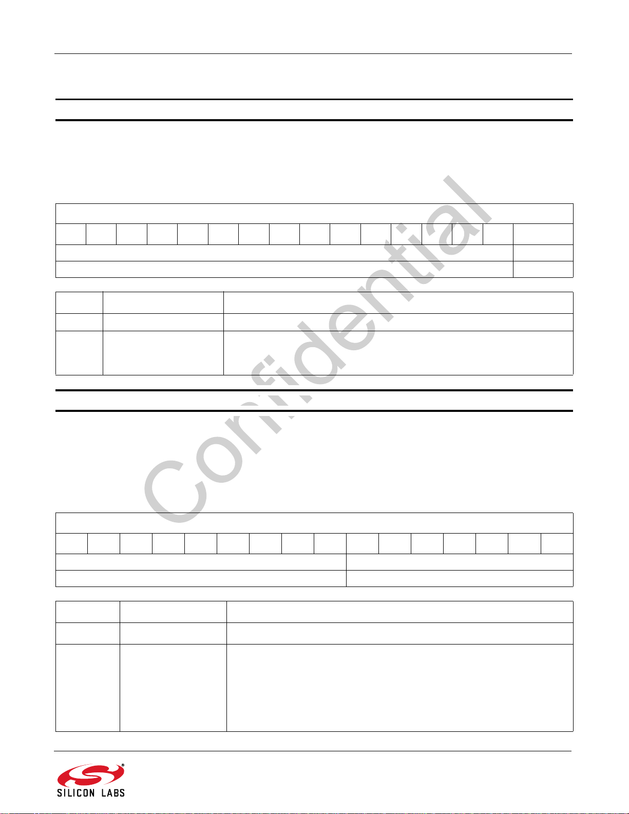
AN543
7.2.2. FM Receiver Properties
Property 0x0302 AUDIO_DE_EMPHASIS
The AUDIO_DE_EMPHASIS property sets the FM Receive deemphasis to 50 or 75 μs. The CTS bit (and optional
interrupt) is set when it is safe to send the next command. This property may only be set or read in powerup mode.
The default is 75 μs.
Default: 0
AUDIO_DE_EMPHASIS
15 14 13 12 11 10 9 8 7 6 5 4 3 2 1 0
0x0000 DE_EMPH
0x0000 0
Bit Name Function
15:1 Reserved Always write 0.
Sets the FM Receive de-emphasis to 50 or 75 μs. Default is 75 µs.
0 DE_EMPH
0=75µsec
1=50µsec
Property 0x0400 FM_SOFT_MUTE_MAX_ATTENUATION
The FM_SOFT_MUTE_MAX_ATTENUATION property sets the maximum attenuation in dB that will be applied by
the softmute feature. The CTS bit (and optional interrupt) is set when it is safe to send the next command. This
property may only be set or read in powerup mode.
Default: 8
Units: dB
FM_SOFT_MUTE_MAX_ATTENUATION
1514131211109876543210
0x000 SMATTN[6:0]
0x000 0x08
Bit Name Function
15:7 Reserved Always write 0.
Sets the maximum attenuation in dB that will be applied by the softmute
feature. Default is 8 dB.
6:0 SMATTN[6:0]
(Si475x-A20 and earlier)
Range is 0-31.
(Si475x-A30 and later)
Range is 0–63 dB.
Rev. 0.9 71
Page 72
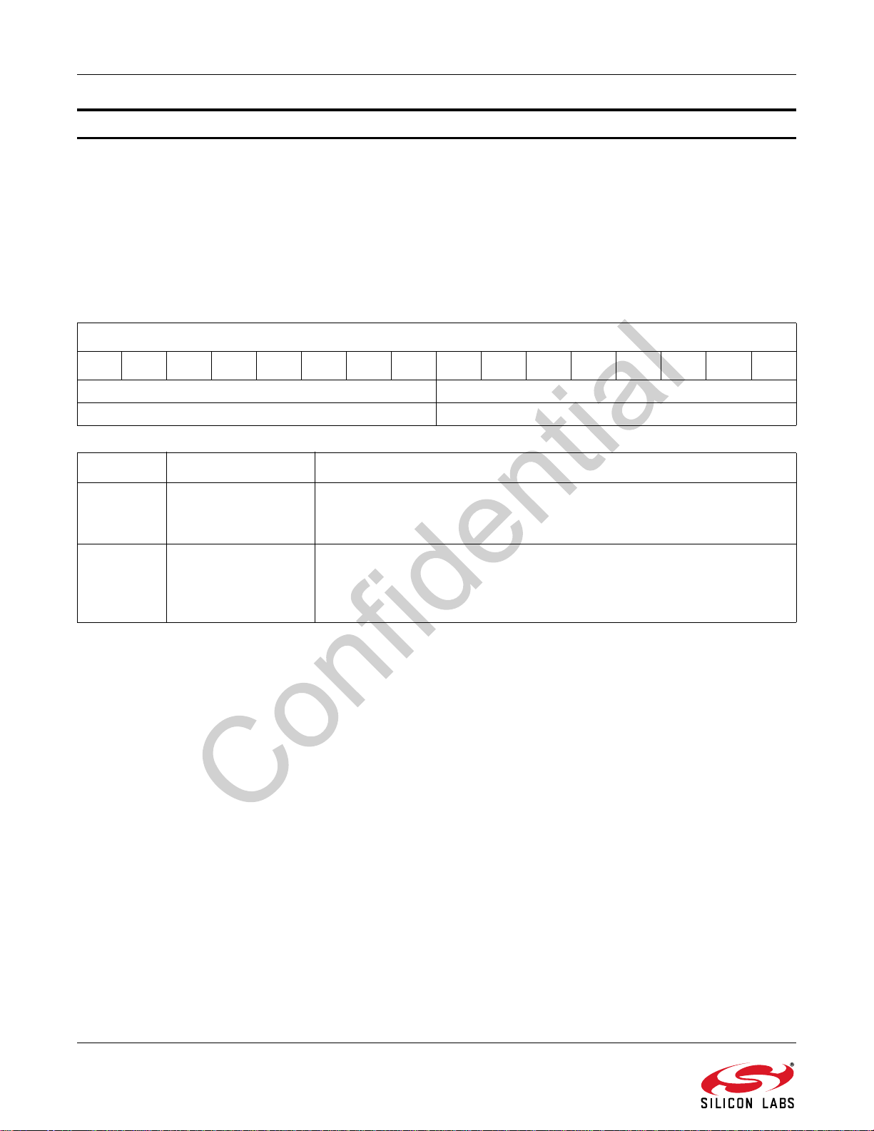
AN543
Property 0x0401 FM_SOFT_MUTE_TRIGGER_THRESHOLD
The FM_SOFT_MUTE_TRIGGER_THRESHOLD property sets the RSSI/SNR threshold in dB to engage softmute.
If USE_RSSI is set in FM_ACF_CONTROL_SOURCE property, then property 0x0401 refers to RSSI threshold. If
USE_RSSI is not set, this property refers to SNR threshold. The CTS bit (and optional interrupt) is set when it is
safe to send the next command. This property may only be set or read in powerup mode.
Si475x-A40 and earlier, Default: 8
Si475x/5xC-A55, Default: 2
Units: dB
FM_SOFT_MUTE_TRIGGER_THRESHOLD
1514131211109876543210
SNR_SMTRGTH[7:0] RSSI_SMTRGTH[7:0]
0x00 0x02
Bit Name Function
15:8 SNR_SMTRGTH[7:0]
7:0 RSSI_SMTRGTH[7:0]
Sets the SNR threshold in dB to engage softmute, default is 0.
Range is -127 ~ 127.
This field is only available in Si475x/5xC-A55.
Sets the RSSI threshold in dB to engage softmute.
Si475x/5xC-A55, Default is 2 dB
Range is 0 to 15 dB for Si475x-A10 and –127 to 127 dB for
later.
Si475x-A20 or
72 Rev. 0.9
Page 73
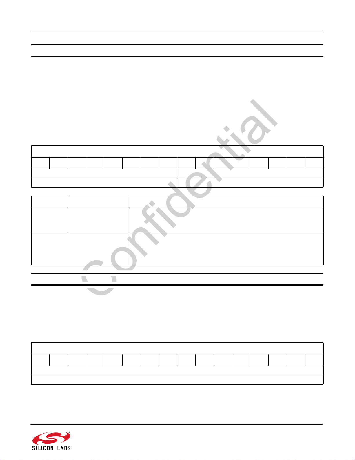
AN543
Property 0x0402 FM_SOFT_MUTE_END_THRESHOLD
The FM_SOFT_MUTE_END_THRESHOLD property sets the SNR threshold in dB at which softmute attenuation
will be set to its maximum value. When the SNR is at this level or lower, the audio attenuation will be set to
FM_SOFT_MUTE_MAX_ATTENUATION. If USE_RSSI is set in the FM_ACF_CONTROL_SOURCE property,
then property 0x0402 refers to the RSSI threshold. If USE_RSSI is not set, this property refers to SNR threshold.
The CTS bit (and optional interrupt) is set when it is safe to send the next command. This property may only be set
or read in powerup mode.
Si475x-A40 and earlier, Default: 0
Si475x/5xC-A55, Default: -6
Units:dB
FM_SOFT_MUTE_END_THRESHOLD
1514131211109876543210
SNR_SMENDTH[7:0] RSSI_SMENDTH[7:0]
0x00 0xFA
Bit Name Function
Sets SNR threshold in dB to end the softmute, default is 0.
15:8 SNR_SMENDTH[7:0]
7:0 RSSI_SMENDTH[7:0]
Property 0x0403 FM_SOFT_MUTE_RELEASE_TIME
The FM_SOFT_MUTE_RELEASE_TIME property sets the maximum time in ms it takes to unmute the audio. The
CTS bit (and optional interrupt) is set when it is safe to send the next command. This property may only be set or
read in powerup mode.
Default: 500
Units: ms
1514131211109876543210
Range is –127 ~ 127
This field is only available in Si475x/5xC-A55.
Sets the RSSI threshold in dBuV to end the softmute.
Si475x/5xC-A55, Default is –6 dB. Si475x-A40 and earlier, default is 0.
Range is 0 to 15 dB for Si475x-A10, and –127 to127 dB for Si475x-A20 or
later.
FM_SOFT_MUTE_RELEASE_TIME
RELEASE[15:0]
0x01F4
Rev. 0.9 73
Page 74
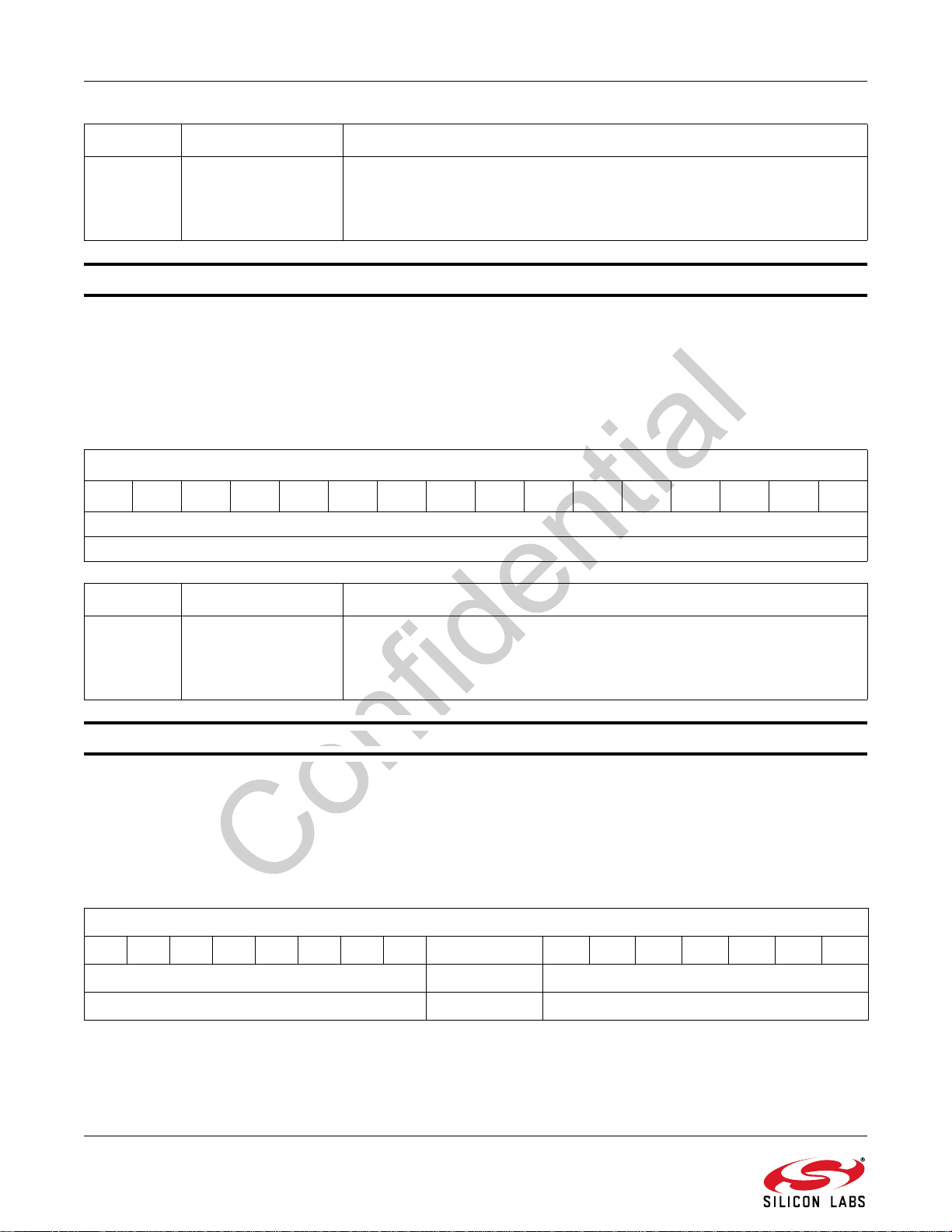
AN543
Bit Name Function
Sets the maximum time in ms it takes to unmute the audio. Note that there
15:0 RELEASE[15:0]
Property 0x0404 FM_SOFT_MUTE_ATTACK_TIME
The FM_SOFT_MUTE_ATTACK_TIME property sets the maximum time in ms it takes to mute the audio. The CTS
bit (and optional interrupt) is set when it is safe to send the next command. This property may only be set or read in
powerup mode.
Si475x-A20 and earlier, Si475x-A40 and later: This property is not available
Units: ms
1514131211109876543210
will be 16 ms of filter delay for RSSI/SNR metric before softmute can
engage/disengage.
Default is 500 ms. Range is 1–32767 ms.
FM_SOFT_MUTE_ATTACK_TIME
ATTACK[15:0]
0x0078
Bit Name Function
Sets the maximum time in ms it takes to mute the audio. Note that there will
15:0 ATTACK[15:0]
Property 0x0405 FM_SOFT_MUTE_MAX_ATTENUATION_AGC (Si4754/55/56/57 Only)
When AGC is engaged, the FM_SOFT_MUTE_MAX_ATTENUATION_AGC property sets the maximum
attenuation in dB that will be applied by the RSSI/SNR softmute feature. The CTS bit (and optional interrupt) is set
when it is safe to send the next command. This property may only be set or read in powerup mode.
Si475x-A20 and earlier: This property is not available.
Si475x-A30 and later, Default: 0x0080
15 14 13 12 11 10 9 8 7 6 5 4 3 2 1 0
be 16 ms of filter delay for RSSI/SNR metric before softmute can engage/
disengage.
Default is 120 ms. Range is 1–32767 ms.
FM_SOFT_MUTE_MAX_ATTENUATION_AGC
0x00 IGNORE_AGC SMATTN[6:0]
0x00 1 0x00
74 Rev. 0.9
Page 75
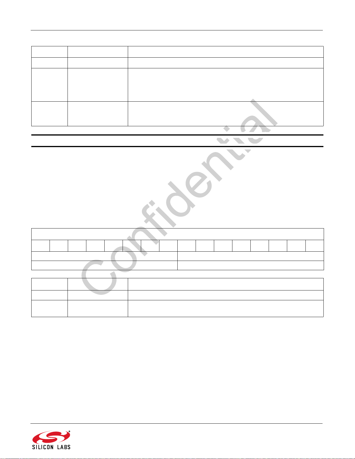
AN543
Bit Name Function
15:8 Reserved Always write to 0.
Selects which set of properties control softmute when AGC is engaged.
7 IGNORE_AGC
6:0 SMATTN[6:0]
Property 0x0406 FM_SOFT_MUTE_TRIGGER_THRESHOLD_AGC (Si4754/55/56/57 Only)
When AGC is engaged, the FM_SOFT_MUTE_TRIGGER_THRESHOLD_AGC property sets the RSSI/SNR
threshold in dB to engage softmute. If USE_RSSI bit is set in FM_ACF_CONTROL_SOURCE property (0x1306),
then this property refers to RSSI threshold. If USE_RSSI bit is not set, this property refers to SNR threshold. The
CTS bit (and optional interrupt) is set when it is safe to send the next command. This property may only be set or
read in powerup mode.
0 = Use properties 0x0405-0x0409 when the AGC is engaged, and properties 0x0400-0x0404 otherwise.
1 = Always use only properties 0x0400-0x0404.
When AGC is engaged, sets the maximum attenuation in dB that will be
applied by the RSSI/SNR softmute feature. Default is 0 dB. Range is 0–
63 dB.
Si475x-A20 and earlier: This property is not available.
Si475x-A30 and later, Default: 8
Units: dB
FM_SOFT_MUTE_TRIGGER_THRESHOLD_AGC
1514131211109876543210
0x00 SMTRGTH_AGC[7:0]
0x00 0x08
Bit Name Function
15:8 Reserved Always write to 0.
7:0 SMTRGTH_AGC[7:0]
When AGC is engaged, sets the RSSI/SNR threshold in dB to engage softmute. Default is 8 dB. Range is –127 to 127 dB.
Rev. 0.9 75
Page 76
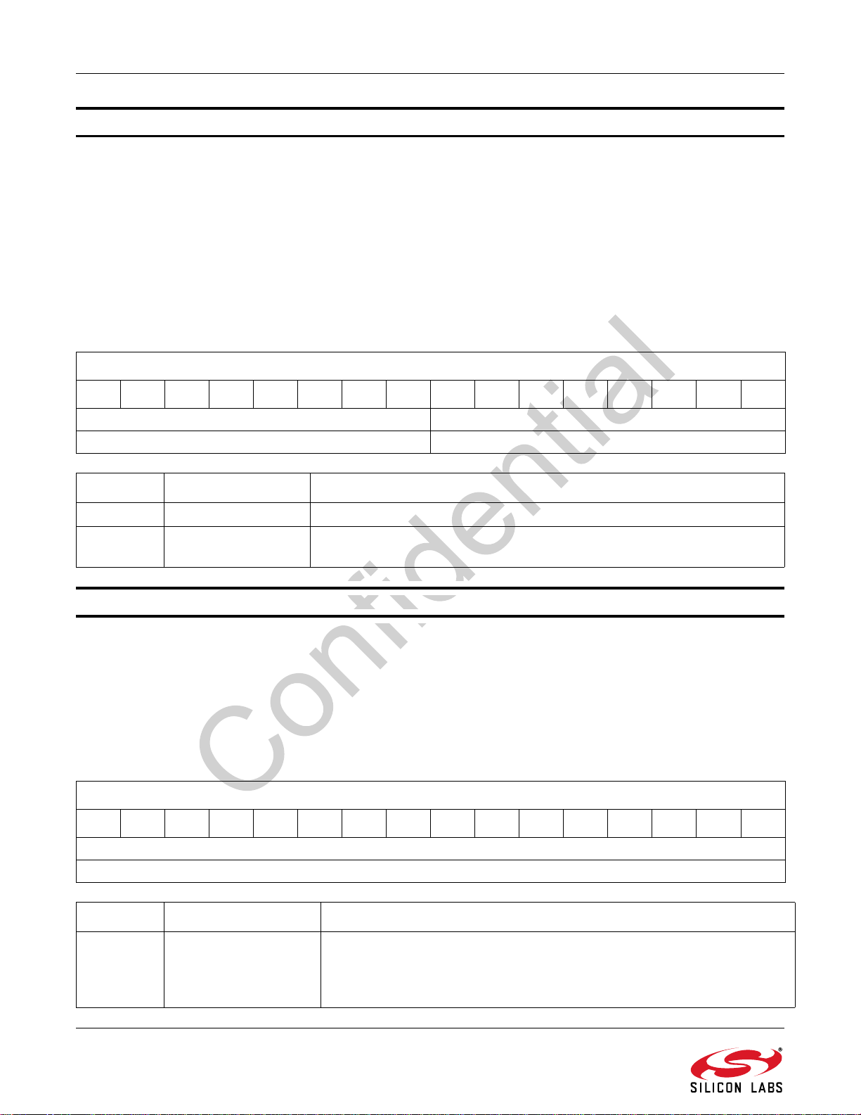
AN543
Property 0x0407 FM_SOFT_MUTE_END_THRESHOLD_AGC (Si4754/55/56/57 Only)
When AGC is engaged, the FM_SOFT_MUTE_END_THRESHOLD_AGC property sets the RSSI/SNR threshold
in dB at which softmute attenuation will be set to its maximum value. When the RSSI/SNR is at this level or lower,
the audio attenuation will be set to FM_SOFT_MUTE_MAX_ATTENUATION_AGC. If USE_RSSI bit is set in
FM_ACF_CONTROL_SOURCE property (0x1306), then this property refers to RSSI threshold. If USE_RSSI bit is
not set, this property refers to SNR threshold. The CTS bit (and optional interrupt) is set when it is safe to send the
next command. This property may only be set or read in powerup mode.
Si475x-A20 and earlier: This property is not available.
Si475x-A30 and later, Default: 0
Units: dB
FM_SOFT_MUTE_END_THRESHOLD_AGC
1514131211109876543210
0x00 SMTRGTH_AGC[7:0]
0x00 0x08
Bit Name Function
15:8 Reserved Always write to 0.
7:0 SMTRGTH_AGC[7:0]
Property 0x0408 FM_SOFT_MUTE_RELEASE_TIME_AGC (Si4754/55/56/57 Only)
When AGC is engaged, the FM_SOFT_MUTE_RELEASE_TIME_AGC property sets maximum time in ms it takes
to unmute the audio. The CTS bit (and optional interrupt) is set when it is safe to send the next command. This
property may only be set or read in powerup mode.
Si475x-A20 and earlier: This property is not available.
Si475x-A30 and later, Default: 500
Units: ms
1514131211109876543210
When AGC is engaged, sets the RSSI/SNR threshold in dB to engage softmute. Default is 8 dB. Range is –127 to 127 dB.
FM_SOFT_MUTE_RELEASE_TIME_AGC
RELEASE_AGC[15:0]
0x01F4
Bit Name Function
Sets the maximum time in ms it takes to unmute the audio. Note that there
15:0 RELEASE_AGC[15:0]
76 Rev. 0.9
will be 16 ms of filter delay for RSSI/SNR metric before softmute can
engage/disengage.
Default is 500 ms. Range is 1–32767 ms.
Page 77
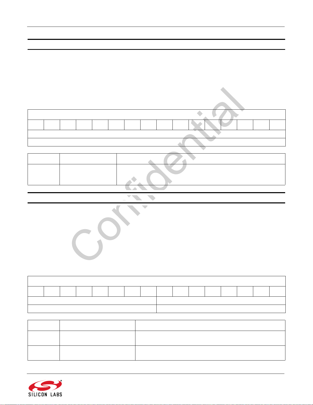
AN543
Property 0x0409 FM_SOFT_MUTE_ATTACK_TIME_AGC (Si4754/55/56/57 Only)
When AGC is engaged, the FM_SOFT_MUTE_ATTACK_TIME_AGC property sets maximum time in ms it takes to
mute the audio. The CTS bit (and optional interrupt) is set when it is safe to send the next command. This property
may only be set or read in powerup mode.
Si475x-A20 and earlier, Si475x-A40 and later: This property is not available
Si475x-A30, Default: 120
Units: ms
FM_SOFT_MUTE_ATTACK_TIME_AGC
1514131211109876543210
ATTACK_AGC[15:0]
0x0078
Bit Name Function
Sets the maximum time in ms it takes to unmute the audio. Note that
15:0 ATTACK_AGC[15:0]
there will be 16 ms of filter delay for RSSI/SNR metric before softmute
can engage/disengage.Default is 120 ms. Range is 1–32767 ms.
Property 0x040A FM_SOFT_MUTE_USN_LIMITS
The FM_SOFT_MUTE_USN_LIMITS property sets the values of USN for which audio is minimally and maximally
muted by USN-based soft mute. The CTS bit (and optional interrupt) is set when it is safe to send the next
command. This property may only be set or read in powerup mode.
Note: USN will generally be negative under signal conditions where soft mute is desirable. The recommended setting is
0xCEE2 (YMIN = –50, YMAX = –30).
Si475x-A20 and earlier, Si475x-A40 and later: This property is not available
Si475x-A30, Default: 0x060E
Units: ms
FM_SOFT_MUTE_USN_LIMITS
1514131211109876543210
YMIN[7:0] YMAX[7:0]
0x06 0x0E
Bit Name Function
15:8 YMIN[7:0]
Sets the value of USN that causes minimum attenuation for USNbased soft mute. Default is 6. Range is –127 to 127.
7:0 YMAX[7:0]
Sets the value of USN that causes maximum attenuation for
USN-based soft mute. Default is 14. Range is –127 to 127.
Rev. 0.9 77
Page 78
AN543
Property 0x040B FM_SOFT_MUTE_USN_ATTENUATION
The FM_SOFT_MUTE_USN_ATTENUATION property sets the limits for soft mute attenuation when driven by
USN. The CTS bit (and optional interrupt) is set when it is safe to send the next command. This property may only
be set or read in powerup mode.
Si475x-A20 and earlier, Si475x-A40 and later: This property is not available.
Si475x-A30, Default: 0x0000
Units: dB
FM_SOFT_MUTE_USN_ATTENUATION
1514131211109876543210
YMIN[7:0] YMAX[7:0]
0x00 0x00
Bit Name Function
15:8 YMIN[7:0]
7:0 YMAX[7:0]
Property 0x040C FM_SOFT_MUTE_USN_ATTACK_TIME
The FM_SOFT_MUTE_USN_ATTACK_TIME property sets maximum time in ms it takes to mute the audio based
on USN. The CTS bit (and optional interrupt) is set when it is safe to send the next command. This property may
only be set or read in powerup mode.
Si475x-A20 and earlier, Si475x-A40 and later: This property is not available.
Si475x-A30, Default: 0x0080
Units: ms
FM_SOFT_MUTE_USN_ATTACK_TIME
1514131211109876543210
Sets the minimum attenuation in dB for USN-based soft mute.
Default is 0. Range is 0–63.
Sets the maximum attenuation in dB for USN-based soft mute.
Default is 0. Range is 0–63.
ATTACK[15:0]
0x0080
Bit Name Function
Sets the USN-based soft mute attack time in ms. Note that there
15:0 ATTACK[15:0]
78 Rev. 0.9
will be 16 ms of filter delay for USN metric before softmute can
engage/disengage. Default is 128. Range is 1–32767.
Page 79
AN543
Property 0x040D FM_SOFT_MUTE_USN_RELEASE_TIME
The FM_SOFT_MUTE_USN_RELEASE_TIME property sets maximum time in ms it takes to unmute the audio
based on USN. The CTS bit (and optional interrupt) is set when it is safe to send the next command. This property
may only be set or read in powerup mode.
Si475x-A20 and earlier, Si475x-A40 and later: This property is not available
Si475x-A30, Default: 0x0100
Units: ms
FM_SOFT_MUTE_USN_RELEASE_TIME
1514131211109876543210
RELEASE[15:0]
0x0004
Bit Name Function
Sets the USN-based soft mute release time in ms. Note that
there will be 16 ms of filter delay for USN metric before softmute
15:0 RELEASE[15:0]
can engage/disengage.
Default is 256.
Range is 1–32767.
Property 0x040E FM_SOFT_MUTE_ASSI200DEV_LIMITS
The FM_SOFT_MUTE_ASSI200DEV_LIMITS property sets the ASSI200DEV threshold to engage softmute and
sets the ASSI200DEV threshold at which softmute attenuation will be set to its maximum value. The CTS bit (and
optional interrupt) is set when it is safe to send the next command. This property may only be set or read in
powerup mode.
Si475x-A10 and earlier: Range: 4–248 ms.
Si475x-A20 and later: Range is 4–4096 ms.
FM_SOFT_MUTE_ASSI200DEV_LIMITS
1514131211109876543210
SMTRGTH_ASSI200DEV[7:0] SMENDTH_ASSI200DEV[7:0]
0x33 0x5A
Bit Name Function
15:8 SMTRGTH_ASSI200DEV[7:0]
7:0 SMENDTH_ASSI200DEV[7:0]
Sets the ASSI200DEV threshold to engage softmute. Default is
51. Range is 0 to 150.
Sets the ASSI200DEV threshold at which softmute attenuation
will be set to its maximum value. Default is 90. Range is 0 to 150.
Rev. 0.9 79
Page 80
AN543
Property 0x040F FM_SOFT_MUTE_ASSI200DEV_ATTENUATION
The FM_SOFT_MUTE_ASSI200DEV_ATTENUATION property sets the maximum attenuation in dB that will be
applied by the ASSI200DEV softmute feature. The CTS bit (and optional interrupt) is set when it is safe to send the
next command. This property may only be set or read in powerup mode.
Si475x-A20 and earlier: This property is not available.
Si475x-A30 and later, Default: 0
Units: dB
FM_SOFT_MUTE_ASSI200DEV_ATTENUATION
1514131211109876543210
0x00 SMATTN_ASSI200DEV[6:0]
0x00 0x00
Bit Name Function
15:8 Reserved Always write to 0.
Sets the maximum attenuation in dB that will be applied by the
7:0 SMATTN_ASSI200DEV[6:0]
ASSI200DEV softmute feature. Default is 0 dB. Range is 0–
63 dB.
Property 0x0410 FM_SOFT_MUTE_ASSI200DEV_ATTACK_TIME
The FM_SOFT_MUTE_ASSI200DEV_ATTACK_TIME property sets maximum time in ms it takes to mute the
audio. The CTS bit (and optional interrupt) is set when it is safe to send the next command. This property may only
be set or read in powerup mode.
Si475x-A20 and earlier: This property is not available.
Si475x-A30 and later, Default: 128
Units: ms
FM_SOFT_MUTE_ASSI200DEV_ATTACK_TIME
1514131211109876543210
ATTACK_ASSI200DEV[15:0]
0x0080
Bit Name Function
Sets the maximum time in ms it takes to mute the audio.
15:0 ATTACK_ASSI200DEV[15:0]
Note that there will be 16 ms of filter delay for the ASSI200DEV
metric before softmute can engage/disengage.
Default is 128 ms. Range is 1–32767 ms.
80 Rev. 0.9
Page 81
AN543
Property 0x0411 FM_SOFT_MUTE_ASSI200DEV_RELEASE_TIME
The FM_SOFT_MUTE_ASSI200DEV_RELEASE_TIME property sets maximum time in ms it takes to unmute the
audio. The CTS bit (and optional interrupt) is set when it is safe to send the next command. This property may only
be set or read in powerup mode.
Si475x-A20 and earlier: This property is not available.
Si475x-A30 and later, Default: 256
Units: ms
FM_SOFT_MUTE_ASSI200DEV_RELEASE_TIME
1514131211109876543210
RELEASE_ASSI200DEV[15:0]
0x0100
Bit Name Function
Sets the maximum time in ms it takes to unmute the audio.
15:0 RELEASE_ASSI200DEV[15:0]
Note that there will be 16 ms of filter delay for the ASSI200DEV
metric before softmute can engage/disengage.
Default is 256 ms. Range is 1–32767 ms.
Property 0x0700 FM_AGC_FE_CONFIG
The FM_AGC_FE_CONFIG property specifies the input path for the RF signal and other FE configuration options.
This property should only be set before the first tune. The CTS bit (and optional interrupt) is set when it is safe to
send the next command. This property may only be set or read in powerup mode. Changes to this property take
effect after the next tune is completed.
Default: 0x0080
FM_AGC_FE_CONFIG
15 14 13 12 11 10 9 8 7 6 5 4 3 2 1 0
0x00 FMLNAZ 1000 INPUTSELECT[3:0]
0x00 0 1000 0x0
Bit Name Function
15:9 Reserved Always write 0.
0 = LNA input impedance is 50
8FMLNAZ
7:4 Reserved Always write 1000.
3:0 INPUTSELECT[3:0]
1 = LNA input impedance is 100
ers splitting a single antenna signal) (Si4754/55/56/57 only)
0 = Received signal comes into FMI pin, out FMO and then the
mixer pin.
1 = Received signal comes directly into the mixer at the FMXIP/
FMIN pins.
.(Normal Operation)
(Loop-through mode: two receiv-
Rev. 0.9 81
Page 82
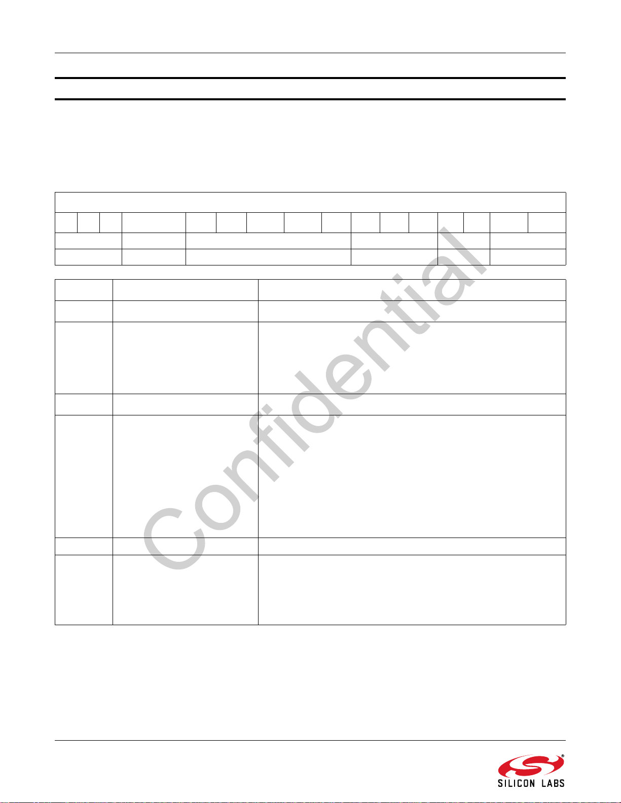
AN543
Property 0x0701 FM_AGC_PD_CONFIG
The FM_AGC_PD_CONFIG property specifies behavior of the FM peak detectors and attenuators. This property
should only be set before the first tune. The CTS bit (and optional interrupt) is set when it is safe to send the next
command. This command may only be sent in powerup mode. Changes to this property take effect after the next
tune is completed.
Default: 0x0270
FM_AGC_PD_CONFIG
151413 12 1110 9 8 765432 1 0
0x0 LNA_MODE 00100 MIXER_PD[2:0] 0x00 LNA_PD[1:0]
0x0 0 00100 0x7 0x00 0x00
Bit Name Function
15:13 Reserved Always write 0.
LNA_MODE default: 0 This property only used when the LNA gain
and one or both of the attenuators are controlled by the same peak
12 LNA_MODE
detector.
0 = Reduce LNA gain and then attenuate with FMAGC1/2.
1 = Attenuate with FMAGC1/2 and then reduce LNA gain.
11:7 Reserved Always write 00100.
MIXER_PD[2:0] default: 0x7.
0 = Peak detector not used.
1 = Controls FMAGC1.
2 = Controls FMAGC2.
6:4 MIXER_PD[2:0]
3:2 Reserved Always write 0.
1:0 LNA_PD[1:0]
3 = Controls FMAGC1 and FMAGC2.
4 = Controls LNA gain.
5 = Controls LNA gain and FMAGC1.
6 = Controls LNA gain and FMAGC2.
7 = Controls LNA gain, FMAGC1 and FMAGC2.
LNA_PD[1:0] default: 0x0
0 = Peak detector not used
1 = Controls FMAGC1
2 = Controls FMAGC2
3 = Controls FMAGC1 and FMAGC2
82 Rev. 0.9
Page 83
AN543
Property 0x0702 FM_LNA_AGC_ATTACK_MS
The FM_LNA_AGC_ATTACK_MS property sets the number of milliseconds the wide-band RF high-peak detector
must be exceeded before attenuating the appropriate block. The peak detectors are only sampled once every 3 to
5 ms. If the peak detector trips, the internal counter is incremented by 4 ms.The CTS bit (and optional interrupt) is
set when it is safe to send the next command. This property may only be set or read in powerup mode.
Default: 4
Units: ms
FM_LNA_AGC_ATTACK_MS
1514131211109876543210
RF_AGC_ATTACK_MS[15:0]
0x0004
Bit Name Function
Number of milliseconds the wideband RF highpeak detector must be exceeded before atten-
15:0 RF_AGC_ATTACK_MS[15:0]
uating the appropriate block.
Default is 4 ms.
Si475x-A10 and earlier: Range: 4–248 ms.
Si475x-A20 and later: Range is 4–4096 ms.
Rev. 0.9 83
Page 84
AN543
Property 0x0703 FM_LNA_AGC_RELEASE_MS
The FM_LNA_AGC_RELEASE_MS property sets the number of milliseconds the wideband RF low-peak detector
must not be exceeded before increasing the gain of the appropriate block. The peak detectors are only sampled
once every 3 to 5 ms. If the peak detector trips, the internal counter is incremented by 4 ms. The CTS bit (and
optional interrupt) is set when it is safe to send the next command. This property may only be set or read in
powerup mode.
Default: 80
Units: ms
FM_LNA_AGC_RELEASE_MS
1514131211109876543210
RF_AGC_RELEASE_MS[15:0]
0x0050
Bit Name Function
15:0 RF_AGC_RELEASE_MS[15:0]
Number of milliseconds the wideband RF low-peak detector must not
be exceeded before increasing the gain of the appropriate block.
Default is 80 ms
Si475x-A10 and earlier: Range: 4–248 ms.
Si475x-A20 and later: Range is 4–4096 ms.
84 Rev. 0.9
Page 85

AN543
Property 0x0704 FM_LNA_AGC_PD_THRESHOLD
The FM_LNA_AGC_PD_THRESHOLD property sets the high threshold and hysteresis for the LNA peak detector.
The high threshold sets the level at which the AGC increases attenuation. The hysteresis is how many dB below
the high threshold the level must drop before the AGC decreases attenuation. It is possible to decrease the
likelihood of intermod break-in by decreasing the peak detector threshold from the default and it is possible to
decrease the likelihood of desensitization by increasing the peak detector threshold. The CTS bit (and optional
interrupt) is set when it is safe to send the next command. This property may only be set or read in powerup mode.
Default: 0x4F05
FM_LNA_AGC_PD_THRESHOLD
1514131211109876543210
HIGH[7:0] HYST[7:0]
0x4F 0x05
Bit Name Function
Sets the level in dBµV at which AGC increases attenuation
HIGH[7:0] Range: 73–87
73 = 73 dBµV
75 = 75 dBµV
15:8 HIGH[7:0]
7:0 HYST[7:0]
77 = 77 dBµV
79 = 79 dBµV
81 = 81 dBµV
83 = 83 dBµV
85 = 85 dBµV
87 = 87 dBµV
Sets how many dB below the high threshold the level must drop
before the AGC decreases attenuation.
HYST[7:0] Range: 3–6
3 = 3 dB
4 = 4 dB
5 = 5 dB
6 = 6 dB
Rev. 0.9 85
Page 86
AN543
Property 0x0705 FM_MIXER_AGC_ATTACK_MS
The FM_MIXER_AGC_ATTACK_MS property sets the number of milliseconds the wideband mixer high-peak
detector must be exceeded before attenuating the appropriate block. The peak detectors are only sampled once
every 3–5 ms. If the peak detector trips, the internal counter is incremented by 4 ms. The CTS bit (and optional
interrupt) is set when it is safe to send the next command. This property may only be set or read in powerup mode.
Si475x-A40 and earlier, Default: 4
Si475x/5xC-A55, Default: 248
Units: ms
FM_MIXER_AGC_ATTACK_MS
1514131211109876543210
MIX_AGC_ATTACK_MS[15:0]
0x00F8
Bit Name Function
15:0 MIX_AGC_ATTACK_MS[15:0]
Number of milliseconds the wideband RF highpeak detector must be exceeded before attenuating the appropriate block.
Si475x/5xC-A55, Default is 248 ms
Si475x-A10 and earlier: Range: 4–248 ms
Si475x-A20 and later: Range is 4–4096 ms
86 Rev. 0.9
Page 87
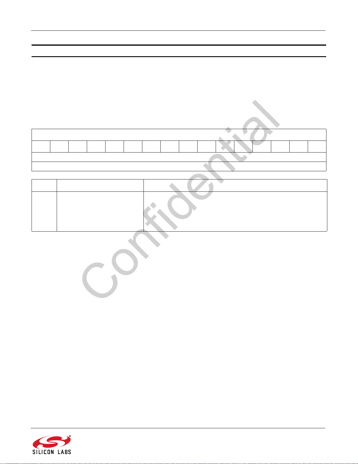
AN543
Property 0x0706 FM_MIXER_AGC_RELEASE_MS
The FM_MIXER_AGC_RELEASE_MS property sets the number of milliseconds the wideband mixer low-peak
detector must not be exceeded before increasing the gain of the appropriate block. The peak detectors are only
sampled once every 3–5 ms. If the peak detector trips, the internal counter is incremented by 4 ms. The CTS bit
(and optional interrupt) is set when it is safe to send the next command. This property may only be set or read in
powerup mode.
Default: 80
Units: ms
FM_MIXER_AGC_RELEASE_MS
1514131211109876543210
MIX_AGC_RELEASE_MS[15:0]
0x0050
Bit Name Function
15:0 MIX_AGC_RELEASE_MS[15:0]
Number of milliseconds the wideband RF low-peak detector must not
be exceeded before increasing the gain of the appropriate block.
Default is 80 ms
Si475x-A10 and earlier: Range: 4–248 ms.
Si475x-A20 and later: Range is 4–4096 ms.
Rev. 0.9 87
Page 88

AN543
Property 0x0707 FM_MIXER_AGC_PD_THRESHOLD
The FM_MIXER_AGC_PD_THRESHOLD property sets the high threshold and hysteresis for the mixer peak
detector
below the high threshold the level must drop before the AGC decreases attenuation. The CTS bit (and optional
interrupt) is set when it is safe to send the next command. This property may only be set or read in powerup mode.
Default: 0x5103
. The high threshold sets the level at which the AGC increases attenuation. The hysteresis is how many dB
FM_MIXER_AGC_PD_THRESHOLD
1514131211109876543210
HIGH[7:0] HYST[7:0]
0x51 0x03
Bit Name Function
Sets the level in dBµV at which AGC increases attenuation.
HIGH[7:0]: Range 79–93.
79 = 79 dBµV.
81 = 81 dBµV.
15:8 HIGH[7:0]
7:0 HYST[7:0]
83 = 83 dBµV.
85 = 85 dBµV.
87 = 87 dBµV.
89 = 89 dBµV.
91 = 91 dBµV.
93 = 93 dBµV.
Sets how many dB below the high threshold the level must drop
before the AGC decreases attenuation.
HYST[7:0] - Range: 3–6.
3 = 3 dB.
4 = 4 dB.
5 = 5 dB.
6 = 6 dB.
88 Rev. 0.9
Page 89
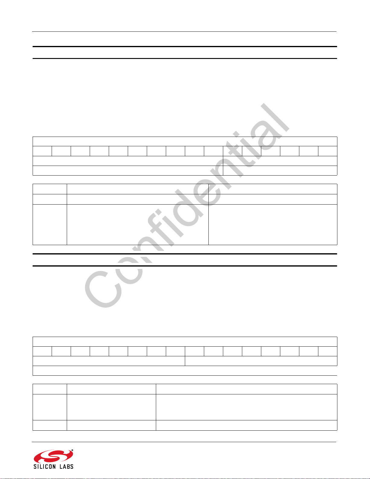
AN543
Property 0x0710 FM_AGC_OVERRIDE
The FM_AGC_OVERRIDE property overrides the AGC setting by disabling the AGC and forcing the gain to be
maximum. The CTS bit (and optional interrupt) is set when it is safe to send the next command. This property may
only be set or read in powerup mode.
Note: In Si475x-A30 only, property FM_AGC_PD_CONFIG should be set to 0x0000 when overriding the AGC with the
FM_AGC_OVERRIDE property. Doing so removes the automatic AGC from peak detector control. Failure to set
FM_AGC_PD_CONFIG when using FM_AGC_OVERRIDE could lead to a conflict which locks the tuner following an
FM_TUNE_FREQ command.
Default: 0x0000
FM_AGC_OVERRIDE
1514131211109876543210
0x000 AGC_OVERRIDE[5:0]
0x000 0x000
Bit Name Function
15:6 Reserved Always write 0.
AGC_OVERRIDE selects whether the AGC is
enabled or disabled.
5:0 AGC_OVERRIDE[5:0]
0 = AGC is enabled.
0x3F = AGC is disabled and set to maximum
gain.
Property 0x071B FM_AGC_RSSI_OFFSET
The FM_AGC_RSSI_OFFSET property sets the value of the offset applied to the RSSI value in order to account
for the front-end gain/loss due to the AGC. The CTS bit (and optional interrupt) is set when it is safe to send the
next command. This property may only be set or read in powerup mode.
Si475x-A10 and before: This property is not available
Si475x-A20 and later, Default: 0
Units: dB
FM_AGC_RSSI_OFFSET
1514131211109876543210
OFFSET[7:0] RSVD[7:0]
0x00 0x00
Bit Name Function
Sets the RSSI offset value to take into account front-end gain/loss.
15:8 OFFSET[7:0]
7:0 Reserved Always write 0.
Default is 0.
Range is –128 to 127.
Rev. 0.9 89
Page 90

AN543
Property 0x071C FM_MIXER_AGC_PD_THRESHOLD_MAX (Si4754/55/56/57 Only)
The FM_MIXER_AGC_PD_THRESHOLD_MAX property sets the maximum threshold for the mixer peak detector
when keyed AGC is engaged. The CTS bit (and optional interrupt) is set when it is safe to send the next command.
This property may only be set or read in powerup mode.
Si475x-A20 and earlier: This property is not available.
Si475x-A30/A40, Default: 85
Si475x/5xC-A55, Default: 89
FM_MIXER_AGC_PD_THRESHOLD_MAX
1514131211109876543210
0x00 MAX_KEY[7:0]
0x00 0x59
Bit Name Function
15:8 Reserved Always write to 0.
Sets the maximum level in dBuV at which AGC increases attenuation.
MAX_KEY [7:0]: Range 79–93
79 = 79 dBµV.
81 = 81 dBµV.
7:0 MAX_KEY[7:0]
83 = 83 dBµV.
85 = 85 dBµV.
87 = 87 dBµV.
89 = 89 dBµV.
91 = 91 dBµV.
93 = 93 dBµV
Si475x/5xC-A55, Default is 89 dBµV.
90 Rev. 0.9
Page 91
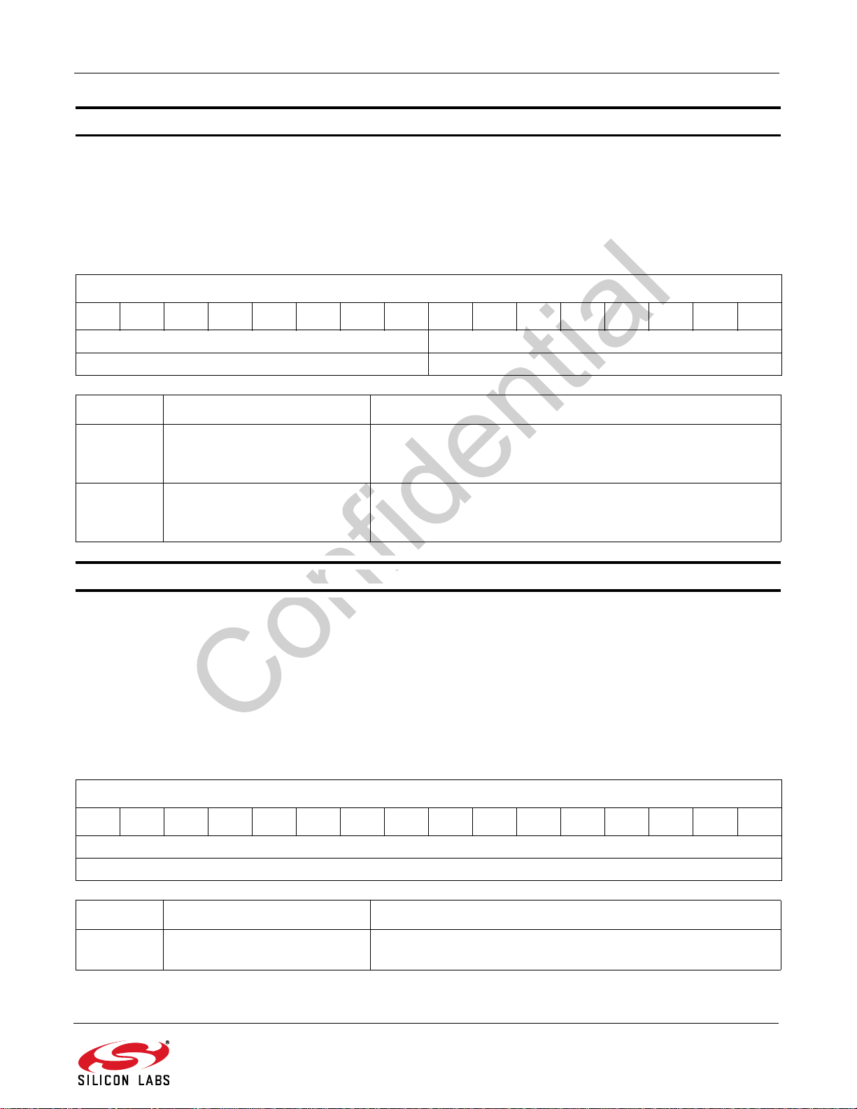
AN543
Property 0x071D FM_AGC_RSSI_MIXER_KEY (Si4754/55/56/57 Only)
The FM_AGC_RSSI_MIXER_KEY property sets the RSSI threshold at which the mixer keyed AGC begins to lower
or raise the peak detector threshold. The CTS bit (and optional interrupt) is set when it is safe to send the next
command. This property may only be set or read in powerup mode.
Si475x-A20 and earlier: This property is not available.
Si475x-A30 and later, Default: 0x140E
FM_AGC_RSSI_MIXER_KEY
1514131211109876543210
KEY_HIGH_THR[7:0] KEY_LOW_THR[7:0]
0x14 0x0E
Bit Name Function
Sets the RSSI threshold at which the mixer keyed AGC begins to
15:8 KEY_HIGH_THR[7:0]
lower the peak detector threshold.
Default is 20 dB. Range: –128 to 127 dB.
Sets the RSSI threshold at which the mixer keyed AGC begins to
7:0 KEY_LOW_THR[7:0]
Property 0x1006 FM_SEEK_TUNE_CHBW_HOLD_TIME
The FM_SEEK_TUNE_CHBW_HOLD_TIME property sets the length of time Channel Filter Bandwidth is held at
specified value after Seek or Tune. The CTS bit (and optional interrupt) is set when it is safe to send the next
command. This property may only be set or read in powerup mode.
Si475x-A10: This property is not available.
Si475x-A20: This feature is not available. Do not write to this property.
Si475x-A30 and later, Default: 80
Units: ms
FM_SEEK_TUNE_CHBW_HOLD_TIME
1514131211109876543210
raise the peak detector threshold.
Default is 14 dB. Range: –128 to 127 dB.
CHBW_HOLD_TIME[15:0]
0x0050
Bit Name Function
15:0 CHBW_HOLD_TIME[15:0]
Sets the length of time Channel Filter Bandwidth is held at specified value after Seek or Tune. Default is 80ms. Range is 4-1000.
Rev. 0.9 91
Page 92
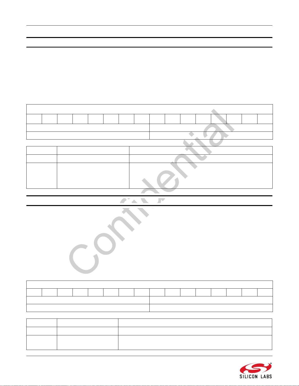
AN543
Property 0x1007 FM_TUNE_CHBW
The FM_TUNE_CHBW property sets the maximum Channel Filter Bandwidth to allow during normal tune.
Narrower Channel Filter Bandwidth could be used based on RSSI, HASSI, LASSI, and ASSI200. The CTS bit (and
optional interrupt) is set when it is safe to send the next command. This property may only be set or read in
powerup mode.
Si475x-A20 and earlier: This property is not available.
Si475x-A30 and later, Default: 80
Units: kHz
FM_TUNE_CHBW
1514131211109876543210
0x00 TUNE_CHBW[7:0]
0x00 0x50
Bit Name Function
15:8 Reserved Always write to 0.
Sets the maximum Channel Filter Bandwidth to allow during nor-
7:0 TUNE_CHBW[7:0]
mal tune. Narrower Channel Filter Bandwidth could be used
based on RSSI, HASSI, LASSI, and ASSI200. Default is 80 kHz.
Range is 0–150.
Property 0x1008 FM_TUNE_AF_CHBW (Si4754/55/56/57 Only)
The FM_TUNE_AF_CHBW property sets the Channel Filter Bandwidth during the AF tune/check. The CTS bit
(and optional interrupt) is set when it is safe to send the next command. This property may only be set or read in
powerup mode.
Note: With Si475x-A40 defaults, the RSSI metric value for AF Check settles within 2 ms. To qualify additional metrics (SNR,
Multipath, USN, LASSI, HASSI, ASSI200) users should set Property 0x2007 FM_VALID_AF_TIME to 0x0005 (5 ms) and
Property 0x1008 FM_TUNE_AF_CHBW to 0x0050 (80 kHz).
Si475x-A20 and earlier: This property is not available Si475x-A30 and A40, Default: 150
Si475x/5xC-A55, Default: 80
Units: kHz
FM_TUNE_AF_CHBW
1514131211109876543210
0x00 TUNE_AF_CHBW[7:0]
0x00 0x50
Bit Name Function
15:8 Reserved Always write to 0.
7:0 TUNE_AF_CHBW[7:0]
Sets the maximum Channel Filter Bandwidth to allow during AF
Si475x/5xC-A55, Default is 80 kHz. Range is
0–150.
tune.
92 Rev. 0.9
Page 93
AN543
Property 0x1100 FM_SEEK_BAND_BOTTOM
The FM_SEEK_BAND_BOTTOM property sets the bottom of the FM band for seek. The CTS bit (and optional
interrupt) is set when it is safe to send the next command. This property may only be set or read in powerup mode.
Default: 8750
Units: 10 kHz
FM_SEEK_BAND_BOTTOM
1514131211109876543210
FMSKFREQL[15:0]
0x222E
Bit Name Function
Sets the bottom of the FM band for seek. Default is 8750.
Range: 6400–10800, 64.0 MHz to 108.0 MHz.
15:0 FMSKFREQL[15:0]
Range: 8750–10790, Worldwide FM excluding Japan.
Range: 6580–7400, OIRT FM.
Range: 7600–9000, Japan FM.
Property 0x1101 FM_SEEK_BAND_TOP
The FM_SEEK_BAND_TOP property sets the top of the FM band for seek. The CTS bit (and optional interrupt) is
set when it is safe to send the next command. This property may only be set or read in powerup mode.
Si475x-A40 and earlier, Default: 10790
Si475x/5xC-A55, Default:10800
Units: 10 kHz
FM_SEEK_BAND_TOP
1514131211109876543210
FMSKFREQH[15:0]
0x2A30
Bit Name Function
Sets the top of the FM band for seek.
Si475x/5xC-A55 Default is 10800.
15:0 FMSKFREQH[15:0]
Range: 6400–10800, 64.0 MHz to 108.0 MHz.
Range: 8750–10790, Worldwide FM excluding Japan. Range: 6580–7400,
OIRT FM.
Range: 7600–9000, Japan FM.
Rev. 0.9 93
Page 94
AN543
Property 0x1102 FM_SEEK_FREQUENCY_SPACING
The FM_SEEK_FREQUENCY_SPACING property selects frequency spacing for FM seek. The CTS bit (and
optional interrupt) is set when it is safe to send the next command. This property may only be set or read in
powerup mode. The default is 100 kHz.
Default: 10
Units: 10 kHz
FM_SEEK_FREQUENCY_SPACING
1514131211109876543210
0x000 FMSKSPACE[4:0]
0x000 0x0A
Bit Name Function
15:5 Reserved Always write 0.
4:0 FMSKSPACE[4:0]
Selects frequency spacing for FM
seek. Default is 10. Range is 1–31.
Property 0x1104 FM_SEEK_CHBW
The FM_SEEK_CHBW property sets the Channel Filter Bandwidth during seek. The CTS bit (and optional
interrupt) is set when it is safe to send the next command. This property may only be set or read in powerup mode.
Si475x-A20 and earlier: This property is not available. Si475x-A30 and A40, Default: 110
Si475x/5xC-A55, Default: 80
Units: kHz
FM_SEEK_CHBW
1514131211109876543210
0x00
0x00
Bit Name Function
15:8 Reserved Always write to 0.
Sets the maximum Channel Filter Bandwidth to allow during seek.
7:0 SEEK_CHBW[7:0]
Si475x/5xC-A55,
Recommended value for 50 or 100 kHz spacing is 80 kHz.
mended value for 200 kHz spacing is 110 kHz.
Default is 80 kHz. Range is 0–150.
SEEK_CHBW[7:0]
0x50
Recom-
94 Rev. 0.9
Page 95
AN543
Property 0x1200 FM_RSQ_INTERRUPT_SOURCE
The FM_RSQ_INTERRUPT_SOURCE property configures interrupt related to Received Signal Quality metrics.
The CTS bit (and optional interrupt) is set when it is safe to send the next command. This property may only be set
or read in powerup mode.
Default: 0
FM_RSQ_INTERRUPT_SOURCE
15 14 13 12 11 10 9 8 7 6 5 4 3 2 1 0
0x00 MULTHINT MULTLINT ISSIHINT
0x00 0 0 0
ISSILINT
Bit Name Function
15:8 Reserved Always write 0.
0: Disable Interrupt.
7MULTHINT
1:Enable interrupt if Multipath level goes above the threshold set by FM_RSQ_MULTIPATH_HIGH_THRESHOLD.
0: Disable Interrupt.
6MULTLINT
1: Enable interrupt if Multipath level falls below the threshold set by FM_RSQ_MULTIPATH_LOW_THRESHOLD.
0: Disable Interrupt.
5 ISSIHINT
1: Enable interrupt if ISSI goes above the threshold set by
FM_RSQ_ISSI_HIGH_THRESHOLD.
0: Disable Interrupt.
4 ISSILINT
1: Enable interrupt if ISSI falls below the threshold set by
FM_RSQ_ISSI_LOW_THRESHOLD.
0: Disable Interrupt.
3 SNRHINT
1: Enable interrupt if SNR goes above the threshold set by FM_RSQ_SNR_HIGH_THRESHOLD.
0: Disable Interrupt.
2SNRLINT
1: Enable interrupt if SNR falls below the threshold set by FM_RSQ_SNR_LOW_THRESHOLD.
0: Disable Interrupt.
1 RSSIHINT
1: Enable interrupt if RSSI goes above the threshold set by FM_RSQ_RSSI_HIGH_THRESHOLD.
0: Disable Interrupt.
0 RSSILINT
1: Enable interrupt if RSSI falls below the threshold set by FM_RSQ_RSSI_LOW_THRESHOLD.
SNRHINT SNRLINT RSSIHINT RSSILINT
0
00 0 0
Rev. 0.9 95
Page 96
AN543
Property 0x1201 FM_RSQ_SNR_HIGH_THRESHOLD
The FM_RSQ_SNR_HIGH_THRESHOLD property sets the high threshold, which triggers the RSQ interrupt if the
SNR is above this threshold. The CTS bit (and optional interrupt) is set when it is safe to send the next command.
This property may only be set or read in powerup mode.
Default: 127
Units: dB
FM_RSQ_SNR_HIGH_THRESHOLD
1514131211109876543210
0x00 SNRH[7:0]
0x00 0x7F
Bit Name Function
15:8 Reserved Write 0 for (+) values and 0xFF for (–) values.
7:0 SNRH [7:0]
Sets the high threshold, which triggers the RSQ interrupt if the SNR is above this
threshold. Default is 127 dB. Range is –128 to 127 in steps of 1 dB.
Property 0x1202 FM_RSQ_SNR_LOW_THRESHOLD
The FM_RSQ_SNR_LOW_THRESHOLD property sets low threshold, which triggers the RSQ interrupt if the SNR
is below this threshold. The CTS bit (and optional interrupt) is set when it is safe to send the next command. This
property may only be set or read in powerup mode.
Default: –128
Units: dB
FM_RSQ_SNR_LOW_THRESHOLD
1514131211109876543210
0xFF SNRL[7:0]
0xFF 0x80
Bit Name Function
15:8 Reserved Write 0 for (+) values and 0xFF for (–) values.
7:0 SNRL [7:0]
Sets low threshold, which triggers the RSQ interrupt if the SNR is below this
threshold. Default is –128 dB. Range is –128 to 127 in steps of 1 dB.
96 Rev. 0.9
Page 97
AN543
Property 0x1203 FM_RSQ_RSSI_HIGH_THRESHOLD
The FM_RSQ_RSSI_HIGH_THRESHOLD property sets the high threshold, which triggers the RSQ interrupt if
RSSI is above this threshold. The CTS bit (and optional interrupt) is set when it is safe to send the next command.
This property may only be set or read in powerup mode.
Default: 127
Units: dBµV
FM_RSQ_RSSI_HIGH_THRESHOLD
1514131211109876543210
0x00 RSSIH[7:0]
0x00 0x7F
Bit Name Function
15:8 Reserved Write 0 for (+) values and 0xFF for (–) values.
7:0 RSSIH [7:0]
Property 0x1204 FM_RSQ_RSSI_LOW_THRESHOLD
The FM_RSQ_RSSI_LOW_THRESHOLD property sets low threshold, which triggers the RSQ interrupt if the RSSI
is below this threshold. The CTS bit (and optional interrupt) is set when it is safe to send the next command. This
property may only be set or read in powerup mode.
Default: –128
Units: dBµV
1514131211109876543210
0xFF RSSIL[7:0]
0xFF 0x80
Bit Name Function
15:8 Reserved Write 0 for (+) values and 0xFF for (–) values.
7:0 RSSIL [7:0]
Sets high threshold, which triggers the RSQ interrupt if the RSSI is above
this threshold. Default is 127 dBµV. Range is –128 to 127 in steps of 1 dB.
FM_RSQ_RSSI_LOW_THRESHOLD
Sets low threshold, which triggers the RSQ interrupt if the RSSI is below this
threshold. Default is –128 dBµV. Range is –128 to 127 in steps of 1 dB.
Rev. 0.9 97
Page 98
AN543
Property 0x1205 FM_RSQ_ISSI_HIGH_THRESHOLD
The FM_RSQ_ISSI_HIGH_THRESHOLD property sets the Image Signal Strength Indicator high threshold, which
triggers the RSQ interrupt if the ISSI is above this threshold. The CTS bit (and optional interrupt) is set when it is
safe to send the next command. This property may only be set or read in powerup mode.
Default: 127
FM_RSQ_RSSI_LOW_THRESHOLD
1514131211109876543210
0x00 HIGH[7:0]
0x00 0x7F
Bit Name Function
15:8 Reserved Always write 0.
7:0 HIGH[7:0]
High threshold for ISSI interrupt in dBr relative to the desired signal.
Default is 127 dBr. Range is –128 to 127.
Property 0x1206 FM_RSQ_ISSI_LOW_THRESHOLD
The FM_RSQ_ISSI_LOW_THRESHOLD property sets the Image Signal Strength Indicator low threshold, which
triggers the RSQ interrupt if the ISSI is below this threshold. The CTS bit (and optional interrupt) is set when it is
safe to send the next command. This property may only be set or read in powerup mode.
Default: –128
FM_RSQ_ISSI_LOW_THRESHOLD
1514131211109876543210
0x00 LOW[7:0]
0x00 0x80
Bit Name Function
15:8 Reserved Always write 0.
7:0 LOW[7:0]
Low threshold for ISSI interrupt in dBr relative to the desired signal.
Default is –128 dBr. Range is –128 to 127.
98 Rev. 0.9
Page 99
AN543
Property 0x1207 FM_RSQ_MULTIPATH_HIGH_THRESHOLD
The FM_RSQ_MULTIPATH_HIGH_THRESHOLD property sets the high threshold, which triggers the RSQ
interrupt if Multipath is above this threshold. Multipath is a measure of AM modulation and can exceed 100%. The
CTS bit (and optional interrupt) is set when it is safe to send the next command. This property may only be set or
read in powerup mode.
Default: 127
FM_RSQ_MULTIPATH_HIGH_THRESHOLD
1514131211109876543210
0x000 MULTH[6:0]
0x000 0x7F
Bit Name Function
15:7 Reserved Always write 0.
6:0 MULTH [6:0]
Sets the high threshold, which triggers the RSQ interrupt if Multipath is
above this threshold. Default is 127. Range is 0–127.
Property 0x1208 FM_RSQ_MULTIPATH_LOW_THRESHOLD
The FM_RSQ_MULTIPATH_LOW_THRESHOLD property sets low threshold, which triggers the RSQ interrupt if
Multipath is below this threshold. Multipath is a measure of AM modulation and can exceed 100%. The CTS bit
(and optional interrupt) is set when it is safe to send the next command. This property may only be set or read in
powerup mode.
Default: 0
FM_RSQ_MULTIPATH_LOW_THRESHOLD
1514131211109876543210
0x000 MULTL[6:0]
0x000 0x00
Bit Name Function
15:7 Reserved Always write 0.
6:0 MULTL[6:0]
Sets low threshold, which triggers the RSQ interrupt if Multipath is below this
threshold. Default is 0. Range is 0–127.
Rev. 0.9 99
Page 100
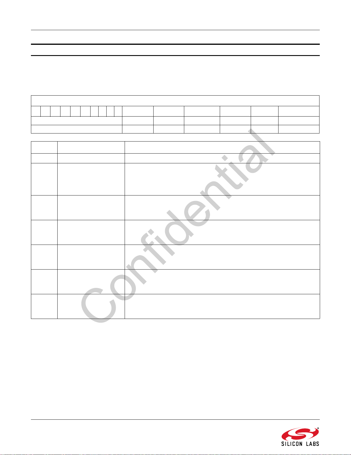
AN543
Property 0x1300 FM_ACF_INTERRUPT_SOURCE
The FM_ACF_INTERRUPT_SOURCE property enables the ACF interrupt sources. The CTS bit (and optional
interrupt) is set when it is safe to send the next command. This property may only be set or read in powerup mode.
Default: 0
FM_ACF_INTERRUPT_SOURCE
15 14 13 12 11 10 9 8 7 6 5 4 3 2 1 0
0x000
0x000
Bit Name Function
15:6 Reserved Always write 0.
5 CHBWH_INT
4BLEND_INT
3 HIBLEND_INT
CHBWH_INT BLEND_INT HIBLEND_INT HICUT_INT CHBW_INT SOFTMUTE_INT
00 0 00 0
(Available on Si475x-A40 only)
When set, enables the Channel Filter Bandwidth High interrupt. Default is 0.
0 = The Channel Bandwidth interrupt is disabled
1 = The Channel Bandwidth interrupt is enabled
When set, enables the blend interrupt. Default is 0.
0 = The blend interrupt is disabled.
1 = The blend interrupt is enabled.
When set, enables the HIBLEND interrupt. Default is 0.
0 = The HIBLEND interrupt is disabled.
1 = The HIBLEND interrupt is enabled.
2 HICUT_INT
1 CHBW_INT
0 SOFTMUTE_INT
When set, enables the HICUT interrupt. Default is 0.
0 = The HICUT interrupt is disabled.
1 = The HICUT interrupt is enabled.
When set, enables the Channel Filter Bandwidth Interrupt. Default is 0.
0 = The Channel Filter Bandwidth interrupt is disabled.
1 = The Channel Filter Bandwidth interrupt is enabled.
When set, enables the softmute interrupt. Default is 0.
0 = The softmute interrupt is disabled.
1 = The softmute interrupt is enabled.
100 Rev. 0.9
 Loading...