


CP2112-EK
CP2112 EVALUATION KIT USER ’S GUIDE
1. Kit Contents
The CP2112 Evaluation Kit contains the following items:
CP2112 Evaluation Board
USB Cable
DVD
Quick Start Guide
2. Relevant Documentation
Application notes can be found on the Interface Application Notes page for all fixed-function devices:
www.silabs.com/interface-appnotes.
AN721: CP210x/CP211x Device Customization Guide — Customize the VID, PID, serial number, and
other parameters stored in the CP2112 one-time programmable ROM.
AN496: CP2112 HID-to-SMBus API Specification — Provides function descriptions and examples for all
of the PC software functions that control the CP2112.
AN495: CP2112 Interface Specification — Describes the HID report format for CP2112 devices.
3. Software Setup
The Software Development Kit (SDK) for the CP2112 kit is included on the kit DVD. The latest version of this
installer can also be downloaded from the www.silabs.com/cp2112ek website. This package includes:
Device Customization Utility
Documentation — data sheet, application notes, user’s guide, quick start guide, etc.
HidSmbusExample — Example software utilizing the CP2112 API interface described in AN496.
Library — repackaged HID DLL and CP2112 API DLL
The Windows installer should launch automatically after inserting the
appropriate directory on th e
system. The CP2112 is an HID device, so a driver does not need to be installed on most operating systems.
DVD to install the software package. Follow the instructions to install the SDK to the
DVD. For Mac and Linux, browse to the
Rev. 0.3 7/13 Copyright © 2013 by Silicon Laboratories CP2112-EK
CP2112-EK
CP2112 EK
SMBus/I2C
Device
SCL
CP2112 HID USB
to SMBus/I
2
C
Bridge
USB
SDA
ground
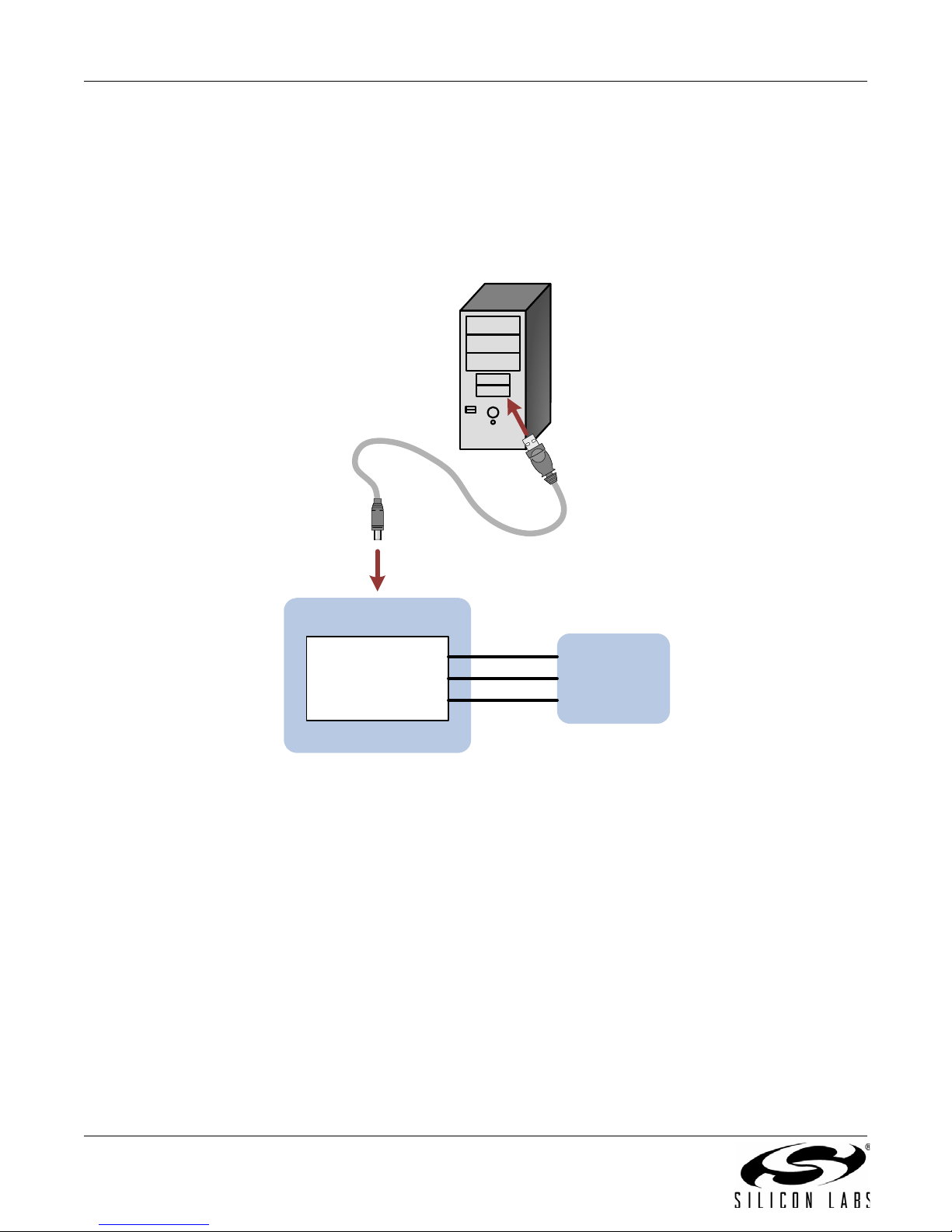
4. CP2112 Hardware Interface
1. Connect the CP2112 evaluation board to a PC as shown in Figure 1.
2. Connect one end of the USB cable to a USB Port on the PC.
3. Connect the other end of the USB cable to the USB connector on the CP2112 evaluation board.
4. Connect the SDA, SCL, and Ground pins on the CP2112 to an SMBus device. External pull-up resistors
are not needed if the pull-up resistors on the CP2112 evaluation board are used.
2 Rev. 0.3
Figure 1. Hardware Setup
CP2112-EK
5. CP2112 Software Interface
The CP2112 is an HID device that uses the standard HID functions available in the operating system. To facilitate
this process in Windows, Silicon Labs packaged the standard HID functions into the SLABHIDDevice DLL in the
CP2112 software package. The HID report structure for the CP2112 is customized for the device and is not
compatible with other HID report structures, like a m ouse or keyboard. AN495, “CP2112 Interface Specification”
describes the custom HID report structure for the CP2112, and AN496, “CP2112 HID-to-SMBus API Specification”
describes the API software functions that can be used to read or write data and control the CP2112 from the PC.
The software application described in “6. CP2112 Windows Application” provides an example of how to use these
functions.
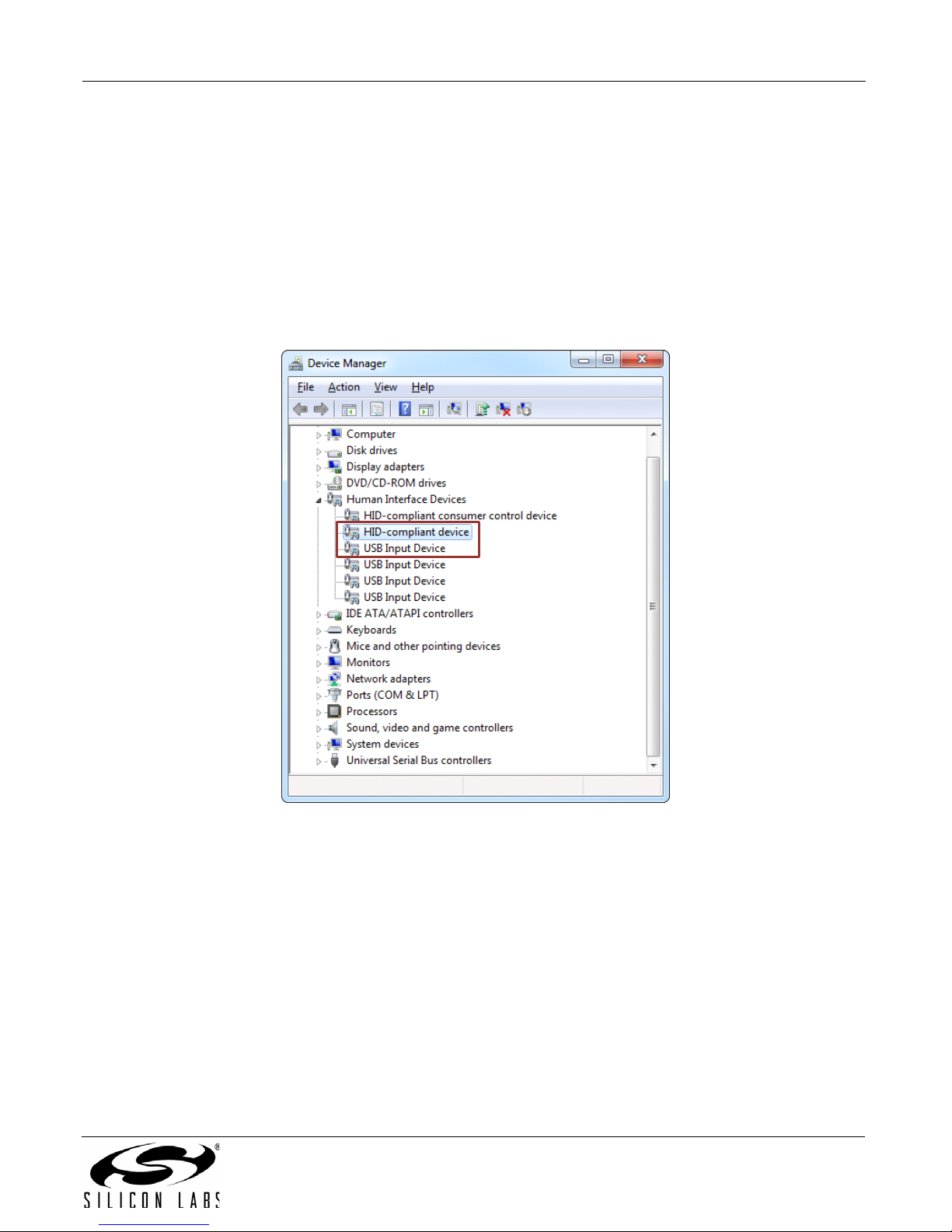
The CP2112 appears as an HID device in Device Manager as shown in Figure 2.
Figure 2. CP2112 in Device Manager
Rev. 0.3 3
CP2112-EK
4
5
6. CP2112 Windows Application
The HID SMBus Example application uses the Windows CP2112 HID-to-SMBus DLL to transmit and receive data
with the CP2112. The application also has access to the CP2112’s GPIO pins. Figure 3 shows a screenshot of the
Windows Application. The following steps describe how to start the application and use some of its features.
1. Ensure that the hardware is connected to a Windows PC as shown in Figure 1. If the device is properly
connected, the red SUSPEND
2. Launch the Hid SMBus Example application, which is foun d by clicking
StartAll ProgramsSilicon LaboratoriesCP2112 Evaluation KitHidSmbus Example.
3. In this application, you can configure the SMBus settings and GPIO pins, customize the device
descriptors, and read/write data over the SMBus interface.
4. Select the appropriate device in the Connection drop down box and click Connect.
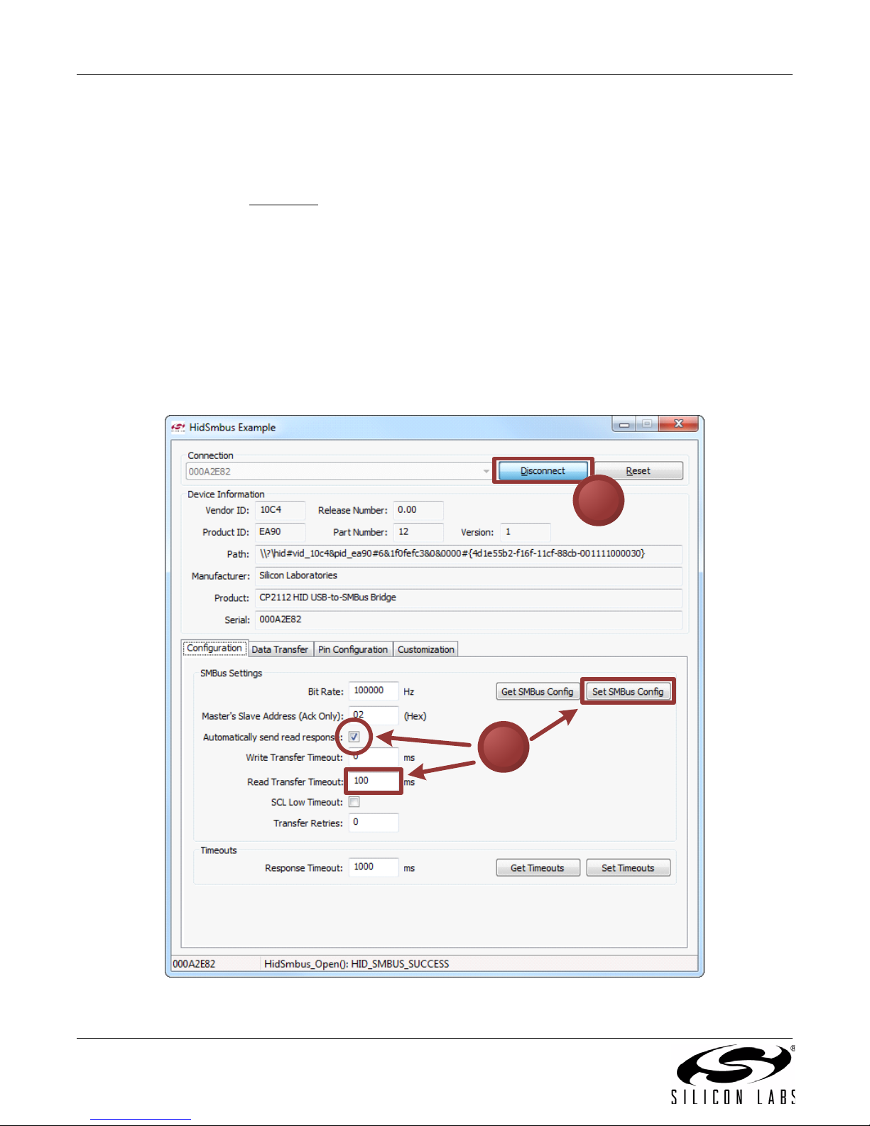
5. The Configuration tab enables setting and getting the SMBus configuration parameters. To set a
parameter, modify the value that is in the corresponding text box or check/uncheck a box and click Set
SMBus Config. To verify that the settings took effect, click Get SMBus Config. These configuration
parameters reset to their default values when the CP2112 is reset.
LED on the CP2112 evaluation board will turn on.
Figure 3. Configuring the SMBus Interface using the Example Application
4 Rev. 0.3
CP2112-EK
6a
6d
6b
6c
6e
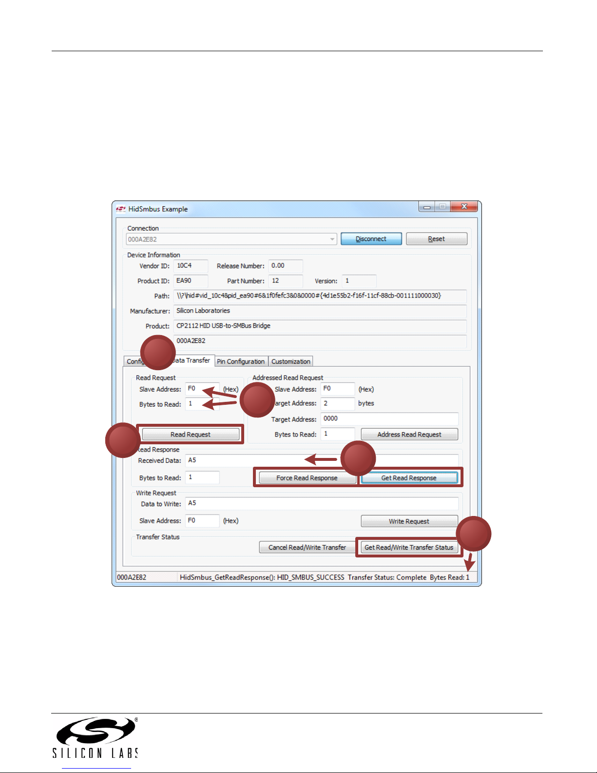
6. To read data from an SMBus device (non-addressed mode):
a. Click the Data Transfer tab.
a. Enter the slave address and the number of bytes to read in the Read Request box.
b. Click the Read Request button.
c. To see the number of bytes that were read back, click Get Read/Write Transfer Status and verify the number of
bytes read at the bottom of the application.
d. Next, click Force Read Response and then Get Read Response until the application reads back the total number
of bytes. The bytes will be shown in the Received Data field. The status of the CP2112 will be shown at the bottom
of the application.
Figure 4. Performing a Non-Addressed Read using the Example Application
Rev. 0.3 5