


SX-500 and SX-510
Serial Device Server
User’s Reference Guide

Part Number 140-00188-180
Revision B
© 2009 Silex Technology America, Inc. All rights reserved. February 2009
Silex Technology America SPECIFICALLY DISCLAIMS THE IMPLIED WARRANTIES OF MERCHANTABILITY AND FITNESS OF THIS PRODUCT FOR A PARTICULAR PURPOSE. Silex shall not be liable for any errors contained in this manual or for any damages resulting from loss of use, data, profits, or any incidental or consequential damages arising from the use of SILEX products or services. The information contained in this documentation is subject to change without notice.
Information and descriptions contained herein are the property of Silex. Such information and descriptions may not be copied, disseminated, or distributed without the express written consent of Silex. This publication is subject to change without notice.
The software embedded in this SX-500 serial device server includes the eCos operating system. eCos and certain other software programs used in the SX-500 are licensed under GNU GPL compatible Free Software Licenses (with the eCos exception clause). In compliance with these licenses, you can obtain the relevant source code at no charge by contacting Silex at support@silexamerica.com.
Trademarks
ExtendView is a trademark of Silex Technology America, Inc. All other company or product names referenced in this document may be trademarks or registered trademarks of their respective owners.
Silex Technology America, Inc.
www.silexamerica.com

Contents |
|
|
About This Reference Guide ...................................................................................................................................... |
1 |
|
Safety Precautions .................................................................................................................................................. |
1 |
|
Emissions Disclaimer .............................................................................................................................................. |
1 |
|
Chapter 1: Introduction ............................................................................................................................................... |
2 |
|
Chapter 2 Installing the Serial Device Server Hardware ............................................................................................ |
3 |
|
Verify Package Contents ........................................................................................................................................ |
3 |
|
Installing the Serial Device Server .......................................................................................................................... |
3 |
|
Monitoring Serial Device Server Status .................................................................................................................. |
5 |
|
Chapter 3 Configuring the Serial Device Server ........................................................................................................ |
7 |
|
Basic Configuration Requirements ......................................................................................................................... |
7 |
|
Configuration Methods ............................................................................................................................................ |
8 |
|
Using the ExtendView Utility to Configure the Serial Device Server (Ethernet Connection) .................................. |
9 |
|
First-Time IP Address Configuration.................................................................................................................... |
13 |
|
Using a Web Browser to Configure the Serial Device Server ............................................................................. |
15 |
|
Using the Internal Command Console to Configure the Serial Device Server .................................................... |
17 |
|
Chapter 4 Using the Serial Device Server with Your Application ............................................................................ |
20 |
|
Serial Port Emulator ............................................................................................................................................. |
20 |
|
Raw TCP connection ........................................................................................................................................... |
21 |
|
RFC 2217 Remote Modem Control Support........................................................................................................ |
22 |
|
ECable Mode ....................................................................................................................................................... |
22 |
|
Print Server Mode ................................................................................................................................................ |
23 |
|
FTP ...................................................................................................................................................................... |
|
23 |
Console Mode Switching ..................................................................................................................................... |
23 |
|
AT Commands ..................................................................................................................................................... |
24 |
|
SNMP Traps and Email Alerts ............................................................................................................................. |
24 |
|
Chapter 5 Advanced Configuration ......................................................................................................................... |
26 |
|
Factory Default Settings....................................................................................................................................... |
26 |
|
Restoring Factory Default Settings .................................................................................................................. |
27 |
|
Modifying TCP/IP Settings ................................................................................................................................... |
27 |
|
Configuring SNMP ............................................................................................................................................... |
29 |
|
Configuring Serial Port Monitor Alert and Trap Configuration ............................................................................. |
31 |
|
Setting up Email Alerts and SNMP Traps ............................................................................................................ |
32 |
|
Using AT Modem Commands.............................................................................................................................. |
33 |
|
Standard AT Commands Supported ................................................................................................................ |
33 |
|
Response Codes.................................................................................................................................................. |
36 |
|
Using ExtendView for Bulk Configuration ............................................................................................................ |
36 |
|
Chapter 6 Troubleshooting ...................................................................................................................................... |
37 |
|
Chapter 7 Product Specifications ............................................................................................................................ |
39 |
|
TCP Port Connections ......................................................................................................................................... |
40 |
|
Appendix A |
Advanced Security Configuration........................................................................................................ |
41 |
Appendix B Console Commands............................................................................................................................ |
45 |
|
Wireless and Network Security Commands ........................................................................................................ |
45 |
|
Port Commands ................................................................................................................................................... |
51 |
|
Contents |
Silex |
Page i |
|
Part Number 140-00188-180 |
|

Server Information Commands ............................................................................................................................ |
52 |
|
Service Commands.............................................................................................................................................. |
53 |
|
String Commands ................................................................................................................................................ |
55 |
|
TCP/IP Commands .............................................................................................................................................. |
56 |
|
Firmware Update.................................................................................................................................................. |
61 |
|
Miscellaneous Commands................................................................................................................................... |
62 |
|
Help Commands .................................................................................................................................................. |
62 |
|
Appendix C Firmware Update Procedures .............................................................................................................. |
63 |
|
Appendix D Safety and Regulatory Notices ............................................................................................................ |
65 |
|
Information for United States Users..................................................................................................................... |
65 |
|
Declaration of Conformity (FCC) (SX-500) .......................................................................................................... |
66 |
|
Information for Canadian Users (IC notice) (SX-500).......................................................................................... |
66 |
|
Information for European Users (SX-500) ........................................................................................................... |
67 |
|
Declaration of Conformity (CE) (SX-500) ............................................................................................................ |
67 |
|
Declaration of Conformity (FCC) (SX-510) .......................................................................................................... |
68 |
|
Information for Canadian Users (IC notice) (SX-510).......................................................................................... |
68 |
|
Appendix E Silex Contact Information ..................................................................................................................... |
70 |
|
Figures |
|
|
Figure 1 SX-500 (Wireless Model) and SX-510 ........................................................................................................ |
2 |
|
Figure 2 TCP/IP Window ........................................................................................................................................ |
27 |
|
Figure 3 Change Password Window ...................................................................................................................... |
28 |
|
Figure 4 Advanced TCP/IP Configuration Window ................................................................................................ |
29 |
|
Figure 5 SNMP Configuration................................................................................................................................. |
31 |
|
Tables |
|
|
Table 1 Development Kit Contents............................................................................................................................ |
3 |
|
Table 2 Status Monitors.............................................................................................................................................. |
5 |
|
Table 3 |
Factory Default Settings ............................................................................................................................ |
26 |
Table 4 |
TCP/IP Settings ......................................................................................................................................... |
28 |
Table 5 |
TCP/IP Configuration Settings................................................................................................................... |
29 |
Table 6 SNMP Commands..................................................................................................................................... |
30 |
|
Table 7 Port Monitor Alert Commands .................................................................................................................. |
31 |
|
Table 8 AT Commands........................................................................................................................................... |
33 |
|
Table 9 Extended AT Commands .......................................................................................................................... |
35 |
|
Table 10 Response Codes ..................................................................................................................................... |
36 |
|
Table 11 |
Product Specifications ............................................................................................................................. |
39 |
Table 12 |
Radio Performance Specifications .......................................................................................................... |
40 |
Table 13 TCP Port Connections ............................................................................................................................. |
40 |
|
Table 14 Network Commands ................................................................................................................................ |
45 |
|
Table 15 Port Commands....................................................................................................................................... |
51 |
|
Table 16 Server Information Commands ............................................................................................................... |
52 |
|
Table 17 Service Commands ................................................................................................................................. |
53 |
|
Table 18 String Commands.................................................................................................................................... |
55 |
|
Table 19 TCP/IP Commands.................................................................................................................................. |
56 |
|
Table 20 Firmware Update ..................................................................................................................................... |
61 |
|
Table 21 Miscellaneous Commands ...................................................................................................................... |
62 |
|
Page ii |
Silex |
Contents |
|
Part Number 140-00188-180 |
|

Contents |
Silex |
Page iii |
Part Number 140-00188-180

About This Reference Guide
Safety Precautions
To prevent damage to the Serial Device Server’s electronic circuit components, follow established ESD practices and procedures for handling static-sensitive devices. All ESD-sensitive components must be stored and shipped in ESD-conductive bags or bubble-wrap and labeled as such using the standardized ESD adhesive warning label.
Ethernet electrical wiring must be at least 6 feet from bare power wiring or lightning rods and associated wires, and at least 6 inches from other types of wire (antenna wires, doorbell wires, wires from transformers to neon signs), steam or hot water pipes, and heating devices.
Protectors and grounding wire placed by the service provider must not be connected to, removed, or modified by the customer.
Emissions Disclaimer
Regulatory compliance information can be found in Appendix D of this manual. Final emission certification per FCC, CE and other agency requirements are the responsibility of the OEM using any printed circuit assemblies or other items used in this developer’s kit in their saleable packaged product.
About This Reference Guide |
Silex |
Page 1 |
|
Part Number 140-00188-180 |
|
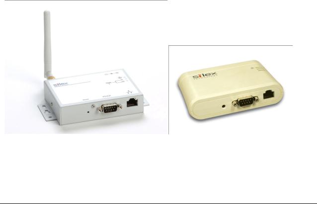
Chapter 1: Introduction
The SX-500 and SX-510 Serial Device Servers provide a complete solution for connecting serial devices to 802.11 wireless or Ethernet wired networks. The following models are available:
SX-500-003x Ethernet model. The SX-500 Ethernet model includes an RS-232-C device interface, 10Base-T/100Base-T Ethernet network interface, and AC power supply.
SX-500-103x Wireless model. The SX-500 Wireless model includes an RS-232-C device interface, an 802.11b/g wireless LAN interface, a 10-Base-T/100Base-T Ethernet network interface, and an AC power supply.
SX-510-103x Wireless model. The SX-510 wireless model includes an RS-232-C/RS-422/RS- 485 device interface, an 802.11a/b/g wireless LAN interface with internal diversity antennas, a 10- Base-T/100Base-T Ethernet network interface, and an AC power supply.
The x in the model number designates the country or region (1 = U.S., 3 = Europe, 5 = Japan; for example, SX-500-1031 is an SX-500 wireless model for the U.S.).
Figure 1 SX-500 (Wireless Model) and SX-510
Introduction |
Silex |
Page 2 |
|
Part Number 140-00188-180 |
|
Chapter 2
Installing the Serial Device Server Hardware
The Serial Device Server includes most of the hardware and software components required for installation. The one item that you will need to purchase separately is a cable to connect your serial device to the Serial Device Server (this cable is not included because of the wide variety of connector types used on serial devices).
Verify Package Contents
The Serial Device Server includes the components listed in Table 1. Please ensure that all materials listed are present and free from visible damage or defects before proceeding. If anything appears to be missing or damaged, please contact Silex.
Table 1 Package Contents
Description
SX-500 or SX-510 Base Unit (SX-500 wireless models include an external pole antenna)
Setup Guide
CD-ROM containing ExtendView software, Serial Port Emulator
Software, and User’s Reference Guide
AC Power Supply with power cord
Warranty Card
Installing the Serial Device Server
Follow the steps below to install the Serial Device Server. The Serial Device Server’s factory default settings should be sufficient for most serial connections; however, some of the configuration settings may have to be changed for your particular installation.
1.Before attempting to install the Serial Device Server, make sure you have installed and set up your serial device as described in the documentation that came with the device.
Installing the Serial Device Server |
Silex |
Page 3 |
|
Part Number 140-00188-180 |
|

2.Write down the 12-digit MAC (Media Access Code) address printed on the label located on the bottom of the Serial Device Server (for example: 004017023F96). You may need this number in order to configure the Serial Device Server.
3.If you have a wireless model, connect the antenna to the unit.
4.Connect the Serial Device Server to your serial device. If you are using RS-232, you may use standard PC cabling (you should normally use a null modem crossover cable). The 9-pin connector pinouts and cabling are as follows:
RS-232 connector pinouts and cabling
If you are using RS-422 or RS-485 in full-duplex or half-duplex modes, you will need a special cable. In addition, if the Silex Serial device Server is the last one in a chain, then a 120-ohm resistor should be placed between pins 2 and 6 (for full-duplex mode) or pins 4 and 5 (for half-duplex mode).
IMPORTANT: IF YOU ARE USING RS-422, RS-485, OR RS-485 HALF-DUPLEX, YOU MUST SET THE SERIAL PORT LINE MODE AS DESCRIBED IN CHAPTER 3 OF THIS MANUAL.
The RS-422 and RS-485 pinouts and cabling are shown in the following diagrams:
RS-422/485 full-duplex connector pinouts and cabling
RS-485 half-duplex connector pinouts and cabling
IMPORTANT NOTE: THE SX-510 RS-422/RS-485 INTERFACE HAS NOT BEEN TESTED FOR COMPLIANCE WITH IEC 60601-1-2:2001/EN60601-1-2 MEDICAL EMC OR ANSI/IEEE Std. C95.1- 1999, RSS-102 SAR STANDARDS. THEREFORE RS-422/485 SHOULD NOT BE ENABLED IF YOU REQUIRE COMPLIANCE WITH ANY OF THESE STANDARDS.
Page 4 |
Silex |
Installing the Serial Device Server |
|
Part Number 140-00188-180 |
|

5.Plug the Serial Device Server power supply adapter into a suitable AC receptacle, and then plug the power supply cable into the Serial Device Server. Alternatively, you can use pin 9 on the 9-pin connector to provide power to the Serial Device Server (1 amp @ +5V is required). The Serial Device Server will run through a sequence of power-up diagnostics for a few seconds.
If the Serial Device Server is operating properly, the LEDs will blink momentarily and then go out, the yellow and green LEDs will illuminate if the wireless network is active, and the orange LED will illuminate, indicating the device is receiving power.
The unit powers up in the Normal mode, which provides for connection from the network to device(s) connected to the serial port of the Serial Device Server.
If the orange LED blinks continuously in a regular pattern, a problem exists. If this is the case, try powering the unit OFF and then ON again.
NOTE: Pin 9 is normally configured for supplying +5V from an external power source in lieu of using the AC power supply adapter. If you wish to use this pin as the Ring Indicator (RI) modem signal on the SX-500 (not available on the SX-510), open. the enclosure and move the jumper on connector JP1 onto pins 2 and 3 of this connector.
6.Connect the Serial Device Server to your network through a switch or hub using a category 5 (CAT5) Ethernet cable. Serial Device Server wireless models automatically detect the presence of this cable, and will switch off the wireless networking functionality as long as the cable is plugged in.
NOTE: SILEX RECOMMENDS USING A HARDWIRED ETHERNET CONNECTION FOR CONFIGURING WIRELESS SERIAL DEVICE SERVERS. If you have a wireless Serial Device Server model and cannot use an Ethernet connection, refer to step 4 in the First Time IP Address Configuration section of this chapter for instructions on how to set up the Serial Device Server using a completely wireless Ad Hoc environment.
7.The Serial Device Server’s IP address must be configured before a network connection is available. If your network offers DHCP (Dynamic Host Configuration Protocol), the Serial Device Server will automatically search for a DCHP server upon power up and obtain an IP address. If your network does not offer DHCP, a static (fixed) IP address must be assigned (see your system administrator for assistance). If you use DHCP, make sure that the length of the DHCP lease is adequate so that the IP address of the Serial Device Server does not change.
Monitoring Serial Device Server Status
You can monitor the Serial Device Server status using the yellow, green and orange LED status indicators on the monitor. Table 2 defines the default functions of the LED status indicators.
|
|
|
Table 2 Status Monitors |
|
|
|
|
|
|
|
|
|
|
|
Function |
State |
|
Status |
|
|
|
|
|
|
|
|
|
|
|
On |
|
The Serial Device Server is receiving power |
|
|
|
Power |
|
|
|
|
|
|
Off |
|
The Serial Device Server is not receiving power |
|
|
|
|
Orange |
|
|
|
||
|
|
|
|
|
|
|
|
Blinking |
|
The Serial Device Server power supply is malfunctioning |
|
||
|
|
|
|
|||
|
|
|
|
|
|
|
|
|
Yellow Off |
|
No network activity |
|
|
|
Network Status |
Green Off |
|
|
|
|
|
|
|
|
|
||
|
Yellow or Green |
|
|
|
|
|
|
Yellow On |
|
10base-T network active |
|
|
|
|
|
Green Off |
|
|
|
|
|
|
|
|
|
|
|
|
|
|
|
|
|
|
|
|
|
|
|
|
|
|
Installing the Serial Device Server |
|
Silex |
Page 5 |
||
|
|
|
Part Number 140-00188-180 |
|
|
|

Function |
State |
Status |
|
|
|
|
Yellow Blinking |
10base-T network data received |
|
Green Off |
|
|
|
|
|
|
|
|
Yellow Off |
100base-TX network active |
|
Green On |
|
|
|
|
|
|
|
|
Yellow Off |
100base-TX network data received |
|
Green Blinking |
|
|
|
|
|
|
|
|
Yellow On |
Wireless network active, if WLAN model |
|
Green On |
|
|
|
|
|
|
|
|
Yellow Blinking |
Wireless network data received, if WLAN model |
|
Green Blinking |
|
|
|
|
|
|
|
Page 6 |
Silex |
Installing the Serial Device Server |
|
Part Number 140-00188-180 |
|

Chapter 3
Configuring the Serial Device Server
This chapter describes the methods for configuring the basic settings of the Serial Device Server, including the IP address, serial port settings, and wireless security. The Serial Device Server also has an extensive range of advanced configuration capabilities that are described in Chapter 5, Appendix A, and Appendix B. The Serial Device Server configuration should be done by a network administrator or another person with technical knowledge of TCP/IP networking and serial communications.
Basic Configuration Requirements
In order to use the Serial Device Server, the following basic parameters must be configured:
TCP/IP Settings:
IP Address
Subnet Mask
Router Address
Note: The TCP/IP settings can be automatically configured using DHCP.
Wireless Configuration Settings:
SSID
Mode (Infrastructure or Ad Hoc)
Channel (required only if using Ad Hoc mode)
Security Settings:
Wireless Encryption Mode (WPA2, WPA, WPA2-WPA, WEP)
Wireless Encryption Settings
Wireless Authentication Mode (WPA-PSK, Open System, Shared Key, TTLS, TLS, LEAP, PEAP, EAP-FAST)
Wired Authentication Mode (TTLS, TLS, PEAP, EAP-FAST)
Authentication Settings
Note: There are numerous possible encryption and authentication settings, and every network can have different settings. Please refer to Appendix A for a detailed summary of these settings.
Serial Port Settings (must match the settings of the attached serial device):
Baud Rate (Speed)
Parity
Configuring the Serial Device Server |
Silex |
Page 7 |
|
Part Number 140-00188-180 |
|

Character Size
Flow Control
Line Mode (RS-232, RS-422, RS-485 full-duplex, RS-485 half-duplex; RS-422 and RS-485 are supported on the SX-510 only)
In addition to the above parameters, the Serial Device Server allows you to configure numerous other capabilities. These other capabilities provide you with the unparalleled flexibility to use the Serial Device Server on virtually any 802.11 or Ethernet network with a wide range of serial devices.
Configuration Methods
There are three ways to configure the Serial Device Server:
ExtendView. ExtendView is a simple Graphical User Interface configuration program for Windows. In addition to setting up the initial Serial Device Server configuration, ExtendView also has the advantage of allowing you to perform bulk configuration of multiple Serial Device Servers simultaneously.
Internal Web Pages (HTTP). You can use any standard web browser to access the Serial Device Server internal web pages. These web pages provide an easy-to-use graphical interface for configuring the Serial Device Server. In order to use the internal web pages for the first time, you must assign the Serial Device Server IP address using some other method (for example, DHCP or arp/ping). This initial IP address assignment need only be done one time.
Internal Command Console. The internal command console provides a sophisticated command line interface for advanced users to configure the Serial Device Server. It can be accessed by connecting a serial cable to the serial port and using console mode switching as descried in chapter 4. Once the IP address has been assigned, the internal command console can also be accessed via TELNET, or via ExtendView and the internal web pages.
If you have a Serial Device Server wireless model, Silex recommends that you temporarily plug the Serial Device into a wired Ethernet network during the configuration process. Although it is possible to configure the Serial Device Server with a completely wireless setup, it is much simpler to perform the process using a wired Ethernet connection. This is primarily because the wireless security on most wireless networks prevents the addition of a new wireless device unless all security parameters are first entered into that device. As a result, you must set up a temporary dedicated ad hoc wireless network in order to configure the Serial Device Server in a completely wireless environment (refer to the step 4 in the First Time IP Address Configuration section of this chapter for instructions on how to set up the Serial Device Server using a completely wireless Ad Hoc environment).
Configuring the Serial Device Server using each of the above methods is described in the following sections of this chapter.
Page 8 |
Silex |
Configuring the Serial Device Server |
|
Part Number 140-00188-180 |
|

Using the ExtendView Utility to Configure the Serial Device Server (Ethernet Connection)
NOTE: Skip this section if you do not have a Windows PC or if you do not have an Ethernet connection available for configuring your Serial Device Server wireless model.
The ExtendView Utility is the easiest way to initially configure the Serial Device Server from a Windows PC because it allows you to directly set the IP address into an unconfigured Serial Device Server, and it allows you to view the IP addresses of all of the Serial Device Servers on your network. It has limited capabilities for configuring 802.1X authentication, but it can be used in conjunction with either the internal web pages or the internal command console for complete configuration capabilities.
ExtendView is a component of the CD-ROM that is included with the Serial Device Server, or it can be downloaded from the Silex website. To install ExtendView, simply follow the on-screen installation instructions. The Serial Device Server configuration procedure is as follows (please note that the screens may be slightly different than shown, depending on the Serial Device Server model and the firmware and software revision levels).
1. Start the ExtendView Utility by clicking on
Start, Programs, silex technology, ExtendView, and then ExtendView.
2. When the Welcome screen appears, click on Next, choose any name for your View Name, select Automatically create a view with default settings (or configure the view to your preferences), and then click Finish.
Configuring the Serial Device Server |
Silex |
Page 9 |
|
Part Number 140-00188-180 |
|

3. Right-click on the Serial Device Server that you want to configure from the displayed list, and then left-click on Configuration. The default Serial Device Server name is SLXxxxxxx (where xxxxxx is the last six digits of the MAC address from the label that is affixed to the Serial Device Server).
4. If you do not have a DHCP server, you will be asked to manually enter an IP address (if you are not sure what IP address to enter, ask your network administrator). Click OK when you are finished.
5. The Server Configuration window will appear. Check the IP address setting to make sure it is correct. If necessary, change the Subnet Mask and Gateway. If you have a WINS server, enter its address or click Use DHCP to Locate WINS Server. If desired, you can configure advanced TCP/IP settings by clicking the Advanced TCP/IP button (refer to Chapter 5 for information). This advanced configuration can be done at a later time, however.
NOTE: If you are using DHCP on your network, the SX-500 should have acquired valid IP settings at this point and no further configuration is necessary. However, for some installations, a static IP address is preferred. If your DHCP server does not allow the SX-500 to keep its assigned IP address permanently, then you must manually assign an IP address. In this case, use a static IP address outside the range reserved for DHCP (see your DHCP server documentation for details). To assign a static IP address, select Set Permanent as the IP Address Resolution, and assign a valid static IP address for your network. Click on OK to save the new settings.
Page 10 |
Silex |
Configuring the Serial Device Server |
|
Part Number 140-00188-180 |
|
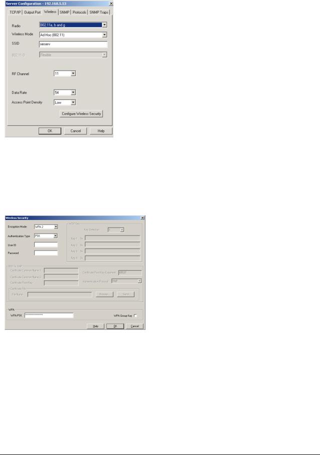
6. Click the Wireless tab to configure the 802.11 wireless settings (for wireless models only; skip to the next section if you have a wired model). To operate on an 802.11 network, the Serial Device Server configuration must be configured with the wireless configuration and security parameters necessary for the Serial Device Server to communicate over your wireless network (check with your network administrator if you do not know these parameters).
Select either Infrastructure (if you are using an access point) or Ad Hoc (point-to-point) as the wireless mode
Enter the SSID for your network
If you are using Ad Hoc, select the RF channel (not required for infrastructure)
The other parameters on this tab do not normally need to be changed (refer to Chapter 5 for information on advanced configuration).
Now click the Configure Wireless Security button to configure the wireless security parameters.
7. If you are using WPA2-PSK, select WPA2 as the Encryption Mode and select PSK as the Authentication Type. If you are using WPAPSK, select WPA as the encryption mode and select PSK as the Authentication Type. For both WPA2-PSK and WPA-PSK you must enter the Pre-Shared Key for your network and select whether you want a Group Key. Note that it is not necessary to enter a User ID or password.
If you are using WEP, select 128-bit or 64-bit as the Encryption Mode and Open Systems or Shared Key as the Authentication Type. Enter the WEP keys in hexadecimal format, and select the transmit key (Key Selection).
ExtendView does not fully support configuration of the 802.1X EAP types, so Silex recommends using the internal web pages or internal command console for 802.1X configuration as described later in this chapter.
Click OK to return to the Server Configuration window, and then click the I/O port tab to configure the serial port.
Configuring the Serial Device Server |
Silex |
Page 11 |
|
Part Number 140-00188-180 |
|

8. You do not need to change any of the settings in this window. Click the Serial Settings button to configure the serial port.
9. Configure the serial port settings so that they match the settings on your device. For example, if your device is set for 9600bps, odd parity, and XON/XOFF flow control, you must change the settings on the Serial Device Server to these settings.
If are using either RS-422 or RS-485 (SX-510 only), select 422 or 485 as the Mode. Select Half as the Duplex type if you are using RS485 half-duplex.
Click OK when you are finished to return to the Server Configuration window and then click OK again.
10. Click OK to save your changes and reset the Serial Device Server. If you are configuring a Serial Device Server wireless model, unplug the Ethernet cable. You can now use the Serial Device Server on your network. You may skip the remaining sections of this chapter, although this information is useful for future reference.
Page 12 |
Silex |
Configuring the Serial Device Server |
|
Part Number 140-00188-180 |
|
First-Time IP Address Configuration
NOTE: Skip this section if you have already configured the SX-500 IP address with ExtendView
If you are configuring the Serial Device Server from a non-Windows computer or if you cannot use an Ethernet connection, you must first configure the Serial Device Server IP address. Note that it is only necessary to perform this task one time -- once the address has been configured, the Serial Device Server can be accessed from any computer on the network that has the appropriate privileges. The steps are as follows:
1.If your network has a DHCP server and you can use an Ethernet connection to the Serial Device Server:
a.Make sure your PC is connected and has access to your network.
b.Connect an Ethernet cable from your network hub to the Serial Device Server (if you have a wireless Serial Device Server and do not have hardwired capabilities, then you must go to Step 4 below for setup instructions).
c.Power on the Serial Device Server.
d.The administration program on most DHCP servers logs the IP address and MAC address of each DHCP client. The MAC address of the Serial Device Server can be found on the label affixed to the unit. If your DHCP server has logged this information, write down the IP address of the Serial Device Server for future reference. You are now ready to configure the Serial Device Server (skip the remainder of this section).
e.If your DHCP server does not provide client information or if you do not have access to the DHCP server, then you can get the IP address by connecting a serial device such as a printer, a Windows PC running HyperTerminal, or another serial device capable of printing ASCII characters to the serial port the Serial Device Server). Your serial device must be set at 115.2Kbps, 8-bit character size, and no parity.
f.With the serial device and Serial Device Server switched on and ready, press the Reset pushbutton on the Serial Device Server. This will cause the Serial Device Server configuration data to be sent to the connected serial device. The serial device should display or print the current IP address assigned to the Serial Device Server by your network DHCP service. Write down this address for future reference. You are now ready to configure the Serial Device Server (skip the remainder of this section).
2.If you can connect the Serial Device Server via Ethernet but do not have a DHCP server, then you must use the following procedure for the first-time IP configuration of the Serial Device Server.
a.Make sure your PC is connected and has access to your network
b.Connect an Ethernet cable from your network hub to the Serial Device Server. The Serial Device Server must be on the same network segment as the PC (that is, there can be no router between the Serial Device Server and the PC).
c.From the Windows Command Prompt (MS-DOS Prompt), the Mac OS X Terminal Utility, or the UNIX/Linux command line, enter the command
arp –s ipaddress macaddress
ping ipaddress
Where ipaddress is the desired IP address of the Serial Device Server and macaddress is the MAC address of the Serial Device Server (found on the label affixed to the Serial Device Server). For example:
Configuring the Serial Device Server |
Silex |
Page 13 |
|
Part Number 140-00188-180 |
|

arp –s 192.168.5.53 00:40:17:00:00:01 ping 192.168.5.53
Note that Windows systems use the format xx-xx-xx-xx-xx-xx for the MAC address (for example, 00-0017-00-00-01).
You will see a reply from the Serial Device Server with the number of bytes and other information if the address was successfully set.
If you get an error message or no response, then the IP address was not set. If this is the case, the Serial Device Server may not be at its default configuration. To reset the Serial Device Server to its default settings, hold down the reset pushbutton for more than five seconds.
d.You are now ready to configure the Serial Device Server (skip the remainder of this section).
NOTE: Skip the following step if you have configured IP address of the Serial Device Server using an Ethernet cable.
3.If you are using a wireless connection for the first-time configuration of the Serial Device Server, you must set up a temporary ad hoc wireless connection as described in the following steps. Please note that because this is a fairly complex process, we do not recommend it unless it is not possible to use a wired connection.
a.Disconnect your PC and the Serial Device Server from your network, and temporarily set the PC settings as follows:
IP address: 192.0.0.191
Wireless Mode: Ad Hoc (sometimes referred to as Peer-to-Peer)
Channel: 11
SSID (or wireless network name): serserv
b.Power on the PC and the Serial Device Server. You can connect to the Serial Device Server by specifying its default IP address of 192.0.0.192 using a web browser as described in the next section. When you have connected to the Serial Device Server, you must then change the IP address and enter the required wireless networking parameters using either the web browser interface or the internal command console (see next two sections) for operation on your wireless network.
c.After you complete the entire Serial Device Server configuration process, you must set your PC back to its original network settings.
Page 14 |
Silex |
Configuring the Serial Device Server |
|
Part Number 140-00188-180 |
|
Using a Web Browser to Configure the Serial Device Server
After you have entered an IP address into the Serial Device Server, you can use any standard web browser to access the internal web pages for configuring the Serial Device Server. Simply specify the IP address of the Serial Device Server in your browser and then follow the steps below:
You may skip this section if you have completely configured the SX-500 using ExtendView. However, if you have advanced configuration requirements, such as 802.1X EAP configuration, then you may need to use the internal web pages as described in this section because ExtendView does not support these capabilities.
IMPORTANT: You must click the Submit button when you have finished configuring an internal web page. If you do not do this, your changes will not be saved.
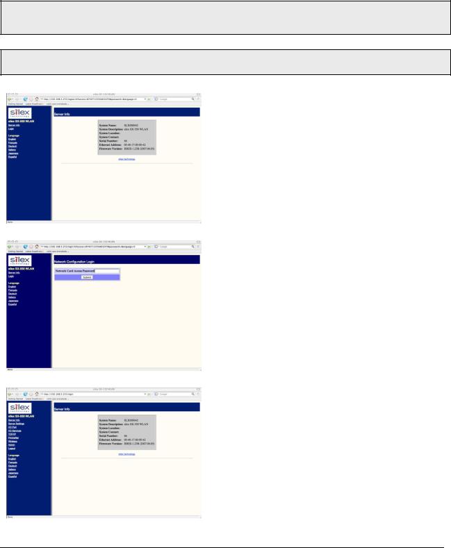
1. When you have connected to the Serial Device Server, you will get the Server Info page. Click Login on the left side of the screen.
2. Enter the password access and press
Submit.
3. You will return to the Server Info page, but new options will be listed on the left side of the screen. Click on TCP/IP.
Configuring the Serial Device Server |
Silex |
Page 15 |
|
Part Number 140-00188-180 |
|

If you used DHCP, verify that the IP address is correctly set. If you used the default 192.0.0.192 IP address, you MUST change it to a new valid IP address. If necessary, change the Subnet Mask and Gateway. It is generally not necessary to change the other parameters on this page (refer to Chapter 5 for advanced configuration information.
Note that on-line help information is available on every configuration page.
Click the Submit button at the bottom of the window (you may need to scroll) to save your changes.
NOTE: If you are using DHCP on your network, the SX500 should have acquired valid IP settings at this point and no further configuration is necessary. However, for some installations, a static IP address is preferred. If your DHCP server does not allow the SX-500 to keep its assigned IP address permanently, then you must manually assign an IP address. In this case, use a static IP address outside the range reserved for DHCP (see your DHCP server documentation for details). To assign a static IP address, select Set Permanent as the IP Address Resolution, and assign a valid static IP address for your network. Click on OK to save the new settings.
4. Click Wireless on the left side of the screen to configure the 802.11a/b/g wireless settings (for WLAN models only; skip to the next section if you have an Ethernet model). To operate on an 802.11a/b/g network, the Serial Device Server configuration must be configured with the wireless configuration and security parameters required to allow the Serial Device Server to communicate over your wireless network (check with your network administrator if you do not know these parameters).
Select either Infrastructure (if you are using an access point) or Ad Hoc (point-to-point) as the wireless mode
Enter the SSID for your network
If you are using Ad Hoc, select the RF channel (not required for infrastructure)
The other parameters on this page do not normally need to be changed (refer to Chapter 5 for information on advanced configuration).
Click the Submit button at the bottom of the window (you may need to scroll) to save your changes.
Now click Configure Network Security to configure the wireless security parameters.
Page 16 |
Silex |
Configuring the Serial Device Server |
|
Part Number 140-00188-180 |
|
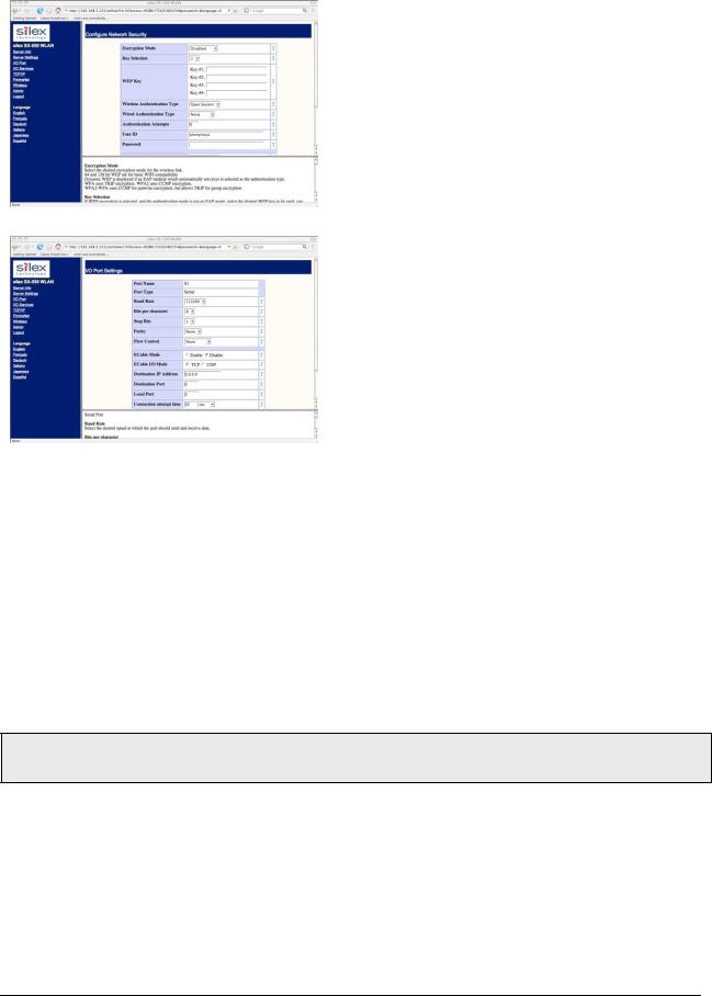
5. Select the appropriate wireless encryption mode and enter the required settings (check with your network administrator for the proper settings if you do not know them). Appendix A lists the possible encryption settings.
Click the Submit button at the bottom of the window (you may need to scroll) to save your changes.
Now click I/O Port on the left side of the screen to configure the serial port.
6. Configure the serial port settings so that they match the settings on your device. For example, if your device is set for 9600bps, odd parity, and XON/XOFF flow control, you must change the settings on the Serial Device Server to these settings.
If you are using RS-422 or RS-485 (SX-510 only), select 422, 485, or 485HD (half-duplex) as the mode.
Click the Submit button at the bottom of the window (you may need to scroll) to save your changes.
When you have finished with all your configuration changes, you must restart the Serial Device Server for these changes to take effect.
You can skip the remainder of this chapter.
Using the Internal Command Console to Configure the Serial Device Server
You may skip this section if you have completely configured the SX-500 using ExtendView or the SX-500 Internal Web Pages.
The Internal Command Console is a command line oriented method for configuring the Serial Device Server. It provides more comprehensive capabilities than either ExtendView or the Internal Web Pages, but is not as easy to use. Advanced users may prefer to use this method because it is concise, fast, and powerful.
To use the Internal Command Console:
1.To access the Internal Command Console, enter the following command from the Windows Command Prompt (MS-DOS Prompt), Mac OS X Terminal Utility, or UNIX/Linux command line:
Configuring the Serial Device Server |
Silex |
Page 17 |
|
Part Number 140-00188-180 |
|
 Loading...