

Page 1

Content
Section 1
System Overview
1.1 Features .................................................................................................................................................... 1-1
Hardware: ...................................................................................................................................... 1-1
Software: ....................................................................................................................................... 1-2
1.2 Optional Accessories ................................................................................................................................ 1-2
1.3 Formats Compatible with the 9800 ..........................................................................................................1-3
1.4 9800 Supported SIA Digital I-III Levels .................................................................................................1-4
1.5 How to Use this Manual ...........................................................................................................................1-5
1.6 Terminology .............................................................................................................................................1-5
1.7 What’s in the Box .................................................................................................................................... 1-6
1.8 How to Contact Silent Knight ..................................................................................................................1-6
..............................................................................................................................1-1
Section 2
Agency Requirements
2.1 Telephone Requirements ..........................................................................................................................2-1
2.2 FCC Warning ...........................................................................................................................................2-1
2.3 UL Requirements .....................................................................................................................................2-2
2.3.1 Hardware Requirements ...................................................................................................................2-2
2.3.2 Operational Requirements ................................................................................................................2-2
2.3.3 Programming Requirements ............................................................................................................. 2-3
............................................................................................................... 2-1
Section 3
Installation
3.1 Environmental specifications ...................................................................................................................3-1
3.2 Electrical Specifications ...........................................................................................................................3-1
3.3 Overview .................................................................................................................................................. 3-2
3.4 Rack Mounting .........................................................................................................................................3-3
3.5 Line Card Installation ............................................................................................................................... 3-5
3.6 Removing Line Cards ..............................................................................................................................3-6
3.7 Telephone Line Connection .....................................................................................................................3-7
3.8 Parallel Printer Connection ......................................................................................................................3-7
3.8.1 Printer Cable Pin-Outs ................................................................................................... ... ..... ...........3-8
3.8.2 Com Ports 1 & 2 ............................................................................................................................... 3-9
3.8.3 Remote Alert Output .........................................................................................................................3-9
3.9 AC Power Cord Connection ..................................................................................................................3-10
3.9.1 Switching to a 230 VAC Power Supply .........................................................................................3-10
3.9.2 How to Verify Earth Ground .......................................................................................................... 3-12
3.10 Battery Connection ................................................................................................................................3-13
3.11 Automation Computer Connection ........................................................................................................3-14
3.11.1 Computer Port Baud Rate Selection ...............................................................................................3-14
.................................................................................................................................................3-1
151051 i
Page 2

Section 4
Operation
4.1 Touchpad Function Buttons .....................................................................................................................4-1
4.2 Displays ....................................................................................................................................................4-3
4.2.1 LED Displays ....................................................................................................................................4-3
4.2.2 LCD Status Display ..........................................................................................................................4-3
4.3 Initial System Power Up ..........................................................................................................................4-6
4.4 Log On / Log Off ............................................................ .........................................................................4-7
4.4.1 Installer Profile .................................................................................................................................4-7
4.4.2 Operator Profile ................................................................................................................................ 4-7
4.4.3 Default User Codes .................................................. .........................................................................4-8
4.4.4 How to log on the system. ................................................................................................................4-8
4.4.5 How to log off the system. ................................................................................................................4-9
4.5 Modes of Operation ................................................... ..... .................................................................... ...4-10
4.5.1 Normal Mode ..................................................................................................................................4-10
4.5.2 Program Mode ............................. ...................................................................................................4-10
4.6 Main Menu ................................................ ..... ........................................................................................4-11
4.6.1 How to display the Main Menu ......................................................................................................4-11
4.6.2 How to Maneuver Through Main Menu .........................................................................................4-12
4.6.3 Call History ........................................ ..... ........................................................................................4-13
4.6.4 System History ................................................................................................................................4-13
4.6.5 System Info .....................................................................................................................................4-14
4.6.6 Set Time & Date ............................................................................................................................4-15
4.6.7 System Restart ................................................................................................................................ 4-16
4.6.8 Printer Menu ................................................. ...... ..... .......................................................................4-17
4.6.9 Program Menu ................................................................................................................................4-24
4.6.10 Diagnostics Menu ...........................................................................................................................4-24
4.7 Listen-In and Hang Up ...........................................................................................................................4-28
4.7.1 Manual (Common) Listen-In Operation .........................................................................................4-28
4.7.2 PBX Operation ................................................................................................................................4-29
4.8 Testing the System ................................................................................................................................. 4-29
.....................................................................................................................................................4-1
4.2.2.1 Adjusting LCD Contrast ........................................................................................................4-4
4.2.2.2 LCD Abbreviations ................................................................................................................4-5
4.5.1.1 Manual Operation ................................................................................................................4-10
How to Manually Acknowledge Calls: ....................................................................................... 4-10
4.5.1.2 Automatic Operation ............................................................................................................4-10
4.5.1.3 Log Only ..............................................................................................................................4-10
4.6.8.1 Print Report .......................................................................................................................... 4-18
How to Print Call History ............................................................................................................4-18
How to Print System History ......................................................................................................4-19
How to Print System Configuration ............................................................................................4-20
How to Print a Test Page .............................................................................................................4-21
4.6.8.2 Edit Event Format ....................................................................................................... ...... ...4-21
4.6.8.3 Configure Printer ................................ ...... ......................................................................... ...4-23
4.6.10.1 Phantom Menu .....................................................................................................................4-25
4.6.10.2 Message Que ........................................................................................................................ 4-26
4.6.10.3 Event Log .............................................................................................................................4-26
4.6.10.4 Format .................................................................................................................................. 4-27
4.6.10.5 LC Debug Mode ...................................................................................................................4-27
151051 ii
Page 3

Section 5
Programming
5.1 How to Enter Program Mode ................................................................................................................... 5-1
5.1.1 Programming Fields ..........................................................................................................................5-1
5.1.2 How to Maneuver Around in Program Mode ...................................................................................5-2
5.2 Programming Choices .............................................................................................................................. 5-2
5.3 General Options .......................................................................................................................................5-3
5.3.1 Operation Mode ................................................................................................................................5-7
5.3.1.1 How to change the operation mode ........................................................................................5-8
5.3.2 Display Options ................................................................................................................................ 5-9
5.3.2.1 How to Change Language Display ......................................................................................5-10
5.3.2.2 How to Change Time Format Display .................................................................................5-10
5.3.2.3 How to Change Date Format Display .................................................................................. 5-11
5.3.2.4 How to Turn “On” or “Off” Daylight Savings. ...................................................................5-11
5.3.2.5 How to Edit ITI Options ......................................................................................................5-12
5.3.2.6 How to Set Sorted Events ....................................................................................................5-13
5.3.2.7 How to Set Hold Last Event ................................................................................................5-13
5.3.3 Communications ............................................................................................................................. 5-14
5.3.3.1 How to Set Up Port Function ............................................................................................... 5-18
5.3.3.2 How to set Com Port 1 Parameters ...................................................................................... 5-18
5.3.3.3 How to Set Com Port 2 Parameters .....................................................................................5-19
5.3.3.4 How to Edit Init String (Com 1, Com 2, and Parallel Port) ................................................. 5-20
To clear an init string: .................................................................................................................5-21
5.3.3.5 How to Set Automation Communication ............................................................................. 5-21
How to Set the Format ................................................................................................................5-21
How Enable or Disable Hex Mode .............................................................................................5-22
How Enable or Disable Heartbeat ...............................................................................................5-22
Time (Period of Heartbeat) ................................................... ...... ................................................5-23
Ack Time (Acknowledge Time) ................................................................................................. 5-24
ITI Options (Only Visible if ITI Gen or ITIComp Formats are Chosen) ...................................5-25
Log Recs (For ITI Formats): .......................................................................................................5-26
XID (Extended ID for ITI Panels): .............................................................................................5-26
SupCh (Supervisory Character): ....................................................... ..... .................................... .5-26
NoData (No Data Character for Log Record): ............................................................................5-26
5.3.3.6 How to Configure the On-board Annunciator Outputs ........................................................5-27
5.3.3.7 How to Configure the Auxiliary Relay Outputs ..................................................................5-28
5.3.4 System Options ...............................................................................................................................5-29
5.3.4.1 How to Change Backup Battery Setting ..............................................................................5-30
To Exit: ........................................................................................................................................5-30
5.3.4.2 How to Set the Receiver ID Number ...................................................................................5-30
To Exit: ........................................................................................................................................5-30
5.3.4.3 How to Set the Normal State of the Auxiliary Relay Contact .............................................5-31
To Exit: ........................................................................................................................................5-31
5.3.5 Message Queue Options .................................................................................................................5-31
5.3.5.1 Set the Message Queue Warning On level ...........................................................................5-32
To Exit: ........................................................................................................................................5-32
5.3.5.2 Set the Message Queue Warning Off Level .........................................................................5-32
To Exit: ........................................................................................................................................5-32
5.3.5.3 Set the maximum Buffer Limit ............................................................................................5-33
To Exit: ........................................................................................................................................5-33
5.4 Line Card Menu .....................................................................................................................................5-33
......................................................................................................................................... 5-1
151051 iii
Page 4

5.4.1 Add Line Card ................................................................................................................................5-37
5.4.2 Edit Line Card ..................................................... ..... ...... .................................................................5-37
5.4.2.1 Handshake Sequence ............................................................................................................5-39
To Change the Handshake Sequence Number: ...........................................................................5-40
To Change the Format Group: ....................................................................................................5-40
To Change the Handshake Delay Time: ..................................................................................... 5-41
To Change the Handshake Duration Time: .................................................................................5-41
To Change the Maximum Handshake Wait Time: ......................................................................5-42
To Change the Acknowledgment Tone Duration Time: .............................................................5-42
5.4.2.2 Line Options .........................................................................................................................5-43
How to Set the Line Card for a Direct Line (Dedicated Line): ...................................................5-43
To Change the Number of Rings Follow These Steps: ...............................................................5-44
To Change the Ring On Time: ....................................................................................................5-44
To Change the Ring Off Time: ...................................................................................................5-45
To Change the Ring Threshold Voltage: ..................................................................................... 5-45
To Change the Phone Line Sample Rate: .................................................................................... 5-46
5.4.2.3 Listen-In ............................................................................................................................... 5-47
To Change the Listen Mode: .......................................................................................................5-47
To Change the PBX String: .........................................................................................................5-48
To Change the Listen-In Timeout: ..............................................................................................5-49
To Edit the Listen-In accounts Lists: ..........................................................................................5-49
To Add a Listen In Account ........................................................................................................5-50
To Edit a Listen In Account ........................................................................................................5-50
To Clear a Listen In Account ......................................................................................................5-50
5.4.2.4 Trap List ...............................................................................................................................5-51
To Add a Trap Account ...............................................................................................................5-51
To Edit a Trap Account ...............................................................................................................5-51
To Clear a Trap Account .............................................................................................................5-52
5.4.2.5 Misc. Line Opt. ....................................................................................................................5-53
To Change the Echo Suppress Setting: .......................................................................................5-53
How to Set Caller ID ...................................................................................................................5-54
To Change the Billing Delay Setting: .........................................................................................5-54
To Change the Hunt Group: ........................................................................................................ 5-55
5.4.2.6 ITI Options Menu .................................................................................................................5-55
ITI SCode Menu: .........................................................................................................................5-57
To Set Date/Time Flag: ...............................................................................................................5-59
To Enable or Disable ITI 300 Baud Negotiation: .......................................................................5-59
5.4.3 Copy Line Cards .............................................................................................................................5-59
5.4.3.1 To Program the Default Settings Into a Line Card ..............................................................5-59
5.4.3.2 Copy the Programming of an Existing Line Card to Another .............................................5-60
5.4.4 Clear Line Card ...............................................................................................................................5-61
To Clear or Delete a Line Card Form the Receiver Follow These Steps: ...................................5-61
5.4.5 View Line Cards .............................................................................................................................5-62
5.5 User List .................................................................................................................................................5-63
5.5.1 Adding a User ......................................... ...... ...... ......................................................................... ...5-64
5.5.2 Editing a User .................................................................................................................................5-65
5.5.3 Clearing a User Out of the Receiver ............................................................................................... 5-67
Section 6
Compatible Reporting Formats
6.1 Formats By Communication Group. ........................................................................................................6-1
6.2 Format Numbers Used In Printer Output .................................................................................................6-3
151051 iv
.....................................................................................6-1
Page 5

Section 7
Troubleshooting
7.1 Error Messages ......................................................................................................................... ................7-1
7.2 Troubleshooting Process ..........................................................................................................................7-5
7.2.1 Removing the Power Supply/Mother Board Assembly ....................................................................7-6
7.2.2 Replacing the Mother Board/Power Supply Assembly ....................................................................7-7
7.3 Safe Mode ................................................................................................................................................7-7
7.4 Updating the Receiver Software ..............................................................................................................7-8
................................................................................................................................7-1
Section 8
Automation Communication Formats
8.1 Introduction .............................................................................................................................................. 8-1
8.1.1 Conventions Observed In This Section ............................................................................................ 8-1
8.2 Silent Knight 9000 Protocol .....................................................................................................................8-2
8.2.1 Data String Description And Special Characters ..............................................................................8-2
8.2.2 Calls From Panels .............................................................................................................................8-4
8.2.3 Long Calls .................................... .....................................................................................................8-5
8.2.4 Bad Data ...........................................................................................................................................8-5
8.2.5 Good Data with Bad Data .................................................................................................................8-5
8.2.6 Validation Byte (V-Byte) ..................................................................................................................8-6
8.2.7 System Messages ..............................................................................................................................8-6
8.2.8 Communication from a Computer to the 9800 .................................................................................8-7
8.2.8.1 ACKing And NACKing Data ................................................................................................8-7
8.2.8.2 Link Test ................................................................................................................................8-8
8.3 SIA CIS (Computer Interface Standard) ..................................................................................................8-9
8.3.1 Data String Description And Special Characters ..............................................................................8-9
8.3.2 Basic Message Format ....................................................................................................................8-11
8.3.3 Modifier Codes ...............................................................................................................................8-12
8.3.4 Long Calls .................................... ...................................................................................................8-13
8.3.5 System Status Messages .................................................................................................................8-14
8.3.6 Heart Beat .......................................................................................................................................8-15
8.3.7 Communication from a Computer to the 9800 ...............................................................................8-16
8.3.7.1 ACKing and NACKing Data ...............................................................................................8-16
8.3.7.2 Link Test ..............................................................................................................................8-17
8.4 ITI Generic Computer Format ............................. ......................................................................... ......... 8-18
8.4.1 Convention Used In This Section ...................................................................................................8-18
8.4.2 Report Record .................................................................................................................................8-18
8.4.2.1 Control Panel Type and Zone Attribution Byte ................................................................... 8-19
8.4.2.2 Extended Panel ID Codes ....................................................................................................8-20
8.4.2.3 Alarm Codes ...................................... ...... ..... .......................................................................8-21
8.4.3 Log Record .....................................................................................................................................8-22
8.4.4 Test Record .....................................................................................................................................8-22
8.4.5 OKAY Record ................................................................................................................................ 8-23
8.4.6 ACKing and NACKing Data ..........................................................................................................8-23
8.5 ITI Computer Interface Format ..............................................................................................................8-24
8.5.1 Convention Used In This Section ...................................................................................................8-24
8.5.2 General Record Structure ................................................................................................................8-24
8.5.3 Report Record .................................................................................................................................8-25
8.5.3.1 Information Field Identifiers ................................................................................................8-27
..................................................................8-1
151051 v
Page 6

8.5.3.2 Panel Type Characters .........................................................................................................8-28
8.5.3.3 Condition Codes ................................................................................................................... 8-29
8.5.4 Test Record .....................................................................................................................................8-29
8.5.5 Supervisory Record .........................................................................................................................8-30
8.5.6 Log Records ....................................................................................................................................8-30
8.5.7 Checksum/Control Field ................................................................................................................. 8-31
8.6 SIA 2000 ................................................................................................................................................ 8-31
8.7 SK EXP (Silent Knight Expanded) ........................................................................................................8-32
8.7.1 SKE Header Block ..........................................................................................................................8-32
Example: ......................................................................................................................................8-32
8.7.2 Call Message Block ....................................................... .................................................................8-33
Example: ......................................................................................................................................8-33
8.7.2.1 Dialer Format .......................................................................................................................8-34
8.7.2.2 Panel Data ............................................................................................................................8-35
Example: ......................................................................................................................................8-36
8.7.2.3 Listen-in Indicator .............................. ...................................................................... ... ......... 8-37
Example: ......................................................................................................................................8-37
8.7.2.4 Trap Account Indicator ........................................................................................................8-38
Example: ......................................................................................................................................8-38
8.7.2.5 Long Call Indicator ....................................... .......................................................................8-38
8.7.2.6 Bad Data Field Indicator ......................................................................................................8-39
Example: ......................................................................................................................................8-39
8.7.3 System Message Block ...................................................................................................................8-39
Example: ......................................................................................................................................8-39
8.7.3.1 System Messages .................................................................................................................8-41
8.7.4 Heart Beat Message Block ..............................................................................................................8-42
Example: ......................................................................................................................................8-42
8.7.5 Validation Byte (V-Byte) ................................................................................................................8-42
8.7.6 ACKing and NACKing Data ..........................................................................................................8-43
8.7.7 Commands Initiated by the Automation Computer ........................................................................8-44
8.7.7.1 Remote Log-on/Log-off ....................................................................................................... 8-45
To Log-in: ...................................................................................................................................8-45
To Log-off: ..................................................................................................................................8-46
8.7.7.2 Force Hang-up Request ........................................................................................................ 8-46
To Force Hang-up: ......................................................................................................................8-46
8.7.7.3 Add or Delete a Listen-in Account ......................................................................................8-47
To Add a Listen-in Account: ....................................................................................................... 8-47
To Delete a Listen-in Account: ...................................................................................................8-47
8.7.7.4 Common Listen-in Extend/End Request .............................................................................. 8-48
To Extend Listen-in: ....................................................................................................................8-48
To End a Listen-in Session: ........................................................................................................8-48
8.7.7.5 PBX Listen-in String ............................................................................................................ 8-49
To Create or Edit PBX String: ....................................................................................................8-49
8.7.7.6 Add or Delete a Trap Account .............................................................................................8-50
To Add a Trap Account: ..............................................................................................................8-50
To Delete a Trap Account: .......................................................................................................... 8-50
8.7.7.7 Link Test Request ................................................................................................................8-51
8.8 US ASCII Character Code .....................................................................................................................8-51
Appendix A
Programming Quick Chart
Index
151051 vi
.........................................................................................................................................................Index-1
..................................................................................................A-1
Page 7

List of Tables
Section 1
System Overview
1.1 Features .................................................................................................................................................... 1-1
1.2 Optional Accessories ................................................................................................................................ 1-2
Table 1-1: Optional Accessories for the 9800 receiver ............................................................................... 1-2
1.3 Formats Compatible with the 9800 ..........................................................................................................1-3
Table 1-2: Formats compatible with the 9800 ..................................... ...... ..................................................1-3
1.4 9800 Supported SIA Digital I-III Levels .................................................................................................1-4
Table 1-3: 9800 and SIA Levels I-III comparison ......................................................................................1-4
1.5 How to Use this Manual ...........................................................................................................................1-5
1.6 Terminology .............................................................................................................................................1-5
1.7 What’s in the Box .................................................................................................................................... 1-6
1.8 How to Contact Silent Knight ..................................................................................................................1-6
.....................................................................................................................................1-1
Section 2
Agency Requirements
2.1 Telephone Requirements ..........................................................................................................................2-1
2.2 FCC Warning ...........................................................................................................................................2-1
2.3 UL Requirements .....................................................................................................................................2-2
........................................................................................................................2-1
Section 3
Installation
3.1 Environmental specifications ...................................................................................................................3-1
3.2 Electrical Specifications ...........................................................................................................................3-1
3.3 Overview .................................................................................................................................................. 3-2
3.4 Rack Mounting .........................................................................................................................................3-3
3.5 Line Card Installation ............................................................................................................................... 3-5
3.6 Removing Line Cards ..............................................................................................................................3-6
3.7 Telephone Line Connection .....................................................................................................................3-7
3.8 Parallel Printer Connection ......................................................................................................................3-7
Table 3-1: External Printer Cable Pin Description ......................................................................................3-8
3.9 AC Power Cord Connection ..................................................................................................................3-10
3.10 Battery Connection ................................................................................................................................3-13
3.11 Automation Computer Connection ........................................................................................................3-14
......................................................................................................................................................3-1
151018 vii
Page 8

Model 9800 Central Station Receiver Installation/Operation Manual
Section 4
Operation
4.1 Touchpad Function Buttons .....................................................................................................................4-1
Table 4-1: Touchpad Buttons Description .................................................................................................. 4-2
4.2 Displays ....................................................................................................................................................4-3
Table 4-2: LED Description ........................................................................................................................4-3
Table 4-3: LCD and Printer Abbreviations .................................................................................................4-5
4.3 Initial System Power Up ..........................................................................................................................4-6
4.4 Log On / Log Off ............................................................ .........................................................................4-7
Table 4-4: Main Menu Option Items by Profile ..........................................................................................4-7
Table 4-5: Default User Codes ....................................................................................................................4-8
4.5 Modes of Operation ................................................... ..... .................................................................... ...4-10
4.6 Main Menu ................................................ ..... ........................................................................................4-11
Table 4-6: Printer Menu Choices ..............................................................................................................4-17
Table 4-7: Event Format Choices and Meaning ........................................................................................4-22
Table 4-8: Phantom Signals Formats List .................................................................................................4-25
4.7 Listen-In and Hang Up ...........................................................................................................................4-28
4.8 Testing the System ................................................................................................................................. 4-29
.........................................................................................................................................................4-1
Section 5
Programming
5.1 How to Enter Program Mode ................................................................................................................... 5-1
Table 5-1: Types of Programming Fields ....................................................................................................5-1
5.2 Programming Choices .............................................................................................................................. 5-2
5.3 General Options .......................................................................................................................................5-3
Table 5-2: General Options Items and Description .....................................................................................5-4
Table 5-3: Operation Mode Choices and Descriptions ...............................................................................5-7
Table 5-4: Display Options and Descriptions .............................................................................................5-9
Table 5-5: Communications Options and Description ..............................................................................5-14
Table 5-6: Initialization String Characters ................................................................................................ 5-20
Table 5-7: ITI Automation Format Options ..............................................................................................5-25
Table 5-8: On-board Annunciator and Auxiliary Relay Options ..............................................................5-27
Table 5-9: System Options ........................................................................................................................5-29
5.4 Line Card Menu .....................................................................................................................................5-33
Table 5-10: Line Card Menu Options .......................................................................................................5-34
Table 5-11: Edit Line Card List Items and Description ............................................................................ 5-38
Table 5-12: Valid Programmable String Characters ................................................................................. 5-48
Table 5-13: Account Characters ................................................................................................................ 5-50
Table 5-14: ITI Options Menu Items ........................................................................................................5-56
Table 5-15: ITI SCode (Security Code) Options .......................................................................................5-58
5.5 User List .................................................................................................................................................5-63
Table 5-16: User List Menu Items and Steps ............................................................................................5-63
Table 5-17: Available Characters ..............................................................................................................5-64
...............................................................................................................................................5-1
viii 151018
Page 9

List of Tables
Section 6
Compatible Reporting Formats
6.1 Formats By Communication Group. ........................................................................................................6-1
Table 6-1: Formats compatible with the 9800 ..................................... ...... ..................................................6-1
6.2 Format Numbers Used In Printer Output .................................................................................................6-3
Table 6-2: Formats By Report Number ............................................... ........................................................6-3
.................................................................................................6-1
Section 7
Troubleshooting
7.1 Error Messages ......................................................................................................................... ................7-1
Table 7-1: Error Messages .......................................................................................................................... 7-1
7.2 Troubleshooting Process ..........................................................................................................................7-5
7.3 Safe Mode ................................................................................................................................................7-7
7.4 Updating the Receiver Software ..............................................................................................................7-8
....................................................................................................................................... 7-1
Section 8
Automation Communication Formats
8.1 Introduction .............................................................................................................................................. 8-1
8.2 Silent Knight 9000 Protocol .....................................................................................................................8-2
Table 8-1: Data String Description ............................................................................................................. 8-2
Table 8-2: Special Characters Used in the Protocol ....................................................................................8-3
Table 8-3: System Messages .......................................................................................................................8-7
8.3 SIA CIS (Computer Interface Standard) ..................................................................................................8-9
Table 8-4: Data String Description ............................................................................................................. 8-9
Table 8-5: Special Characters .................................................................................................................... 8-10
Table 8-6: Modifier Codes Used With The 9800 ......................................................................................8-12
Table 8-7System Status Messages ............................................................................................................8-15
8.4 ITI Generic Computer Format ............................. ......................................................................... ......... 8-18
Table 8-8: Number and ITI Digit Equivalent ............................................................................................8-18
Table 8-9: Report Record Components .....................................................................................................8-18
Table 8-10: Upper Nibble Description ......................................................................................................8-19
Table 8-11: Lower Nibble Description ...................................................................................................... 8-19
Table 8-12: Extended Panel ID Codes (XID) ........................................................................................... 8-20
Table 8-13: Alarm Code and Description .................................................................................................8-21
Table 8-14: Log Record Components and Description .............................................................................8-22
Table 8-15: Test Record Components and Description ............................................................................8-22
Table 8-16: Okay Record Components and Description ........................................................................... 8-23
8.5 ITI Computer Interface Format ..............................................................................................................8-24
Table 8-17: Number and ITI Digit Equivalent .......................................................................................... 8-24
Table 8-18: Type of Record Identifiers .....................................................................................................8-24
Table 8-19: Record Components ...............................................................................................................8-25
Table 8-20: Report Record Components and Description ........................................................................8-26
Table 8-21: Information Field Identifiers ..................................................................................................8-27
Table 8-22: Panel Type Characters ...........................................................................................................8-28
Table 8-23: Panel Type Characters (Continued) ....................................................................................... 8-28
Table 8-24: C ondition Codes and Descriptions ........................................................................................8-29
.................................................................................8-1
151018 ix
Page 10

Model 9800 Central Station Receiver Installation/Operation Manual
Table 8-25: C ondition Codes and Descriptions ........................................................................................8-29
Table 8-26: Test Record Information Fields and Descriptions .................................................................8-29
Table 8-27: Log Record Information Fields And Descriptions ................................................................8-30
8.6 SIA 2000 ................................................................................................................................................ 8-31
Table 8-28: Checksum Verification Process .............................................................................................8-31
8.7 SK EXP (Silent Knight Expanded) ........................................................................................................8-32
Table 8-29: SKE Header Block Components Description ......................................... ..... ...... ....................8-32
Table 8-30: Call Message Components and Description .......................................................................... 8-33
Table 8-31: Dialer Format Types By Code ...............................................................................................8-34
Table 8-32: Panel Data Identifiers and Descriptions ................................................................................. 8-35
Table 8-33: Call Message Components .....................................................................................................8-36
Table 8-34: Call Message With Listen-in Data .........................................................................................8-37
Table 8-35: Trap Account Indicator Components .....................................................................................8-38
Table 8-36: Bad Data Field Indicator Components ................................................................................... 8-39
Table 8-37: System Message Components ...............................................................................................8-40
Table 8-38: System Messages ...................................................................................................................8-41
Table 8-39: Link Test Components ...........................................................................................................8-42
Table 8-40: R esponse Messages by the 9800 Receiver ............................................................................8-44
Table 8-41: Command Requests by Identifiers ......................................................................................... 8-45
Table 8-42: Log-in Request Components .................................................................................................8-45
Table 8-43: Log-off Request Components ................................................................................................8-46
Table 8-44: Force Hang-Up Request Components ...................................................................................8-46
Table 8-45: Add Listen-in Account Request Components .......................................................................8-47
Table 8-46: Delete a Listen-in Account Request Components .................................................................8-47
Table 8-47: Extend Listen-in Period Request Components ...................................................................... 8-48
Table 8-48: Extend Listen-in Period Request Components ...................................................................... 8-48
Table 8-49: Delete a Listen-in Account Request Components .................................................................8-49
Table 8-50: Add Listen-in Account Request Components .......................................................................8-50
Table 8-51: Delete a Listen-in Account Request Components .................................................................8-50
8.8 US ASCII Character Code .....................................................................................................................8-51
Table 8-52: US ASCII Character Code .....................................................................................................8-51
Appendix A
Programming Quick Chart
Table A-1: Programming Quick Chart ....................................................................................................... A-1
Index
.........................................................................................................................................................Index-1
..................................................................................................A-1
x 151018
Page 11

Section 1
System Overview
This manual describes installation, operation, and programming of the Model 9800 Central
Station Receiver. The 9800 can be used as a desk-top receiver, however it must be rackmounted for UL listed installations. This section will list features, optional accessories,
compatible formats, and SIA options supported. This section also contains conventions held
throughout the manual, terminology relevant to this product, and other information.
1.1 Features
Hardware:
• Supports both 120 and 240 VAC installations at 60 and 50Hz operation.
• External annunciation with auxiliary Form C dry contact relay. (Programmable)
• On-board PZT alert. (Programmable.)
• 1 parallel port.
• 2 serial ports.
• 2 rear SBUS connectors.
• Modular configuration for easy replacement and repair.
• 4 line LCD Display with 20 characters for each line.
• On-board touchpad for manual operation and programming.
• LEDs to indicate system operations.
• Rack mountable design.
• One line card will communicate with all supported formats.
• Supports up to 12 line cards which operate independent of each other.
• Line card parameters are stored on the MCPU for faster removal and replacement.
• Line cards support Caller ID and Caller Name Delivery.
• Line cards are individually programmable for format priority and ring parameters.
• Line cards support direct connect phone lines monitoring.
151018 1-1
Page 12

Model 9800 Central Station Receiver Installation/Operation Manual
Software:
• Programmable display options for time and date information.
• View or print the history information by priority or by call or by event.
• Two user profiles to control user access to the receiver.
• Supports up to 40 users.
• Listen-in and trap accounts support wild card variables. Up to 20 accounts available per
line card. (20 for listen-in and 20 for trap accounts.)
• Listen-in selectable for direct, hook flash, or PBX phone system.
• Programmable port configuration for automation, printer and backup support.
• 500 event history buffer.
1.2 Optional Accessories
The following accessories for the Model 9800 receiver are available from Silent Knight Sales
Department unless otherwise indicated. You can contact Silent Knight Sales Department by
phone or by mail. The Sales Department’s toll free and local numbers are 800-446-6444 and
612-493-6435. Our mailing address is 7550 Meridian Circle, Maple Grove, MN 55369-4927.
Table 1-1: Optional Accessories for the 9800 receiver
Silent Knight
Item
Line card 9810 The line card monitors the phone line, detects ring and processes
Backup battery 6712 (See Section
Printer cable Not available from
Rack-mounting
cabinet
Blank filler panels Not available from
Parallel printer SK320 Silent Knight Model 9 800 receiver requires the SK320 parall el
Model Number (if
applicable)
3.10 for installation.)
Silent Knight
Not available from
Silent Knight
Silent Knight
Description/Comments
the message from the communi cating panel.
A 12VDC 7ah battery which will provide a minimum 4 hours of
backup power during an AC power loss. (See Section 2.3.2 for UL
backup power requirements.)
A standard 25-pin cable used to connect the 9800 rec eiver to an
external parallel printer.
Used to rack mount the 9800 recei ver as required by UL. (See
Section 2.3.1 for specifica ti ons and vendor information.)
Used to fill up any unused cab inet spaces as required by UL.
printer to generate a hardcopy of report history.
1-2 151018
Page 13

System Overview
1.3 Formats Compatible with the 9800
The 9800 receiver is compatible with all Silent Knight UL listed communicators.
Table 1-2 shows the formats that the 9800 receiver can decode and the handshake frequency
groups which accommodate that format (see Section 5.4 for line card programming). Each
line card can decode every format listed below. Setting the handshake order only prioritizes
the type of communication done by each line card. Section 6 of this manual describes the
formats in greater detail.
Table 1-2: Formats compatible with the 9800
Format Name Handshake
BFSK 1400 or 2300 Hz
SK FSK, FSK 0, FSK 80 1400 or 2300 Hz
SK FSK 1, FSK 1, FSK 81 1400 or 2300 Hz
FSK II, FSK 86 1400 Hz
SK 4+2 1400 Hz
SK 3+1/3+1 Extended 1400 or 2300 Hz
Sescoa 3+1/Franklin 3+1 2300 Hz
Radionics 3+1 Che c ksum 1400 or 2300 Hz
4+1 Extended 1400 or 2300 Hz
FBI 4+3+1 1400 or 2300 Hz
SX-III, SX-IVA 2225 Hz
SX-IVB 2225 Hz
ITI SX-V 2225 Hz
ITI Commander 2225 Hz
ITI RF Commander, Harbor Gard 2225 Hz
ITI Commander 2000, LifeGard 2225 Hz
ITI CareTaker+, SecurityPro 4000 2225 Hz
ITI UltraGard 2225 Hz
SIA DCS 2225 Hz
SIA 2000 (pending approval) 2225 Hz
Ademco Contact I D 1400 and 2300 Hz
Ademco Super Fast 1400 and 2300 Hz
Acron Touch Tone 1400 and 2300 Hz
Ademco Express 1400 and 2300 Hz
DTMF 4+2 1400 and 2300 Hz
151018 1-3
Page 14
Model 9800 Central Station Receiver Installation/Operation Manual
1.4 9800 Supported SIA Digital I-III Levels
Table 1-3 compares the 9800 receiver to SIA Digital Compatibility Levels I, II, and III and
indicates which of them we comply with.
Table 1-3: 9800 and SIA Levels I-III comparison
9800 Function/Capability Transmitter Receiver
Support Tonal Acknowledgments required required
Support N blocks with Zone Numbers Only required required
Support single Account Block per Call required required
Support O Blocks (optional) required
Level I
Level II
Support X Blocks (optional) required
Support 300 Baud (Fast) (optional) required
Support Configuration Block required required
Support Data Acknowledgments required required
Support Modifier codes id, da and ti. (optional) required
Support Multiple Account Blocks per Call (optional) required
Support E Blocks (optional) required
Support Data Codes with Units Numbers (optional) required
Level III
Support RECEIVER call out and Access Passcode required required
Support Reverse Channel C Blocks required required
Support Reverse Channel P Blocks required (optional)
Support Reverse Channel A Blocks (optional) required
Support Dynami c block and Group Sizes (optional) required
Support Listen-in (optional) required
Support A Blocks to RECEIVER (optional) required
Support V-Channel communication (optional) (optional)
1-4 151018
Page 15

System Overview
1.5 How to Use this Manual
This manual contains information on how to install, operate and program the 9800 receiver.
Silent Knight strongly suggests that the manual be reviewed in its entirety to become familiar
with procedures and parameters of the product. Once you are familiar with the product, the
manual can be used as a reference document.
The manual uses the following conventions:
• A small graphic of each touchpad button is used to represent which touchpad key is to be
pressed for a given operation. For example, an up-arrow would be shown as:
• /&'GLVSOD\ This typeface represents messages that appear on the LCD.
• +] This typeface represents an editable field that appears on the LCD.
• Pages of the manual are numbered by section. For example, a page numbered as “5-1” is
Page 1 of Section 5.
• When this manual refers to defau lt se ttin gs, it m eans programmable options set at the factory. Any programming after the receiver is powered up will change these setting.
1.6 Terminology
This section lists terminology that is specific to this product and their meaning.
Term Meaning
Communication Group Silent Knight has separated the different types of communication by
handshake type. These handshake types can be assigned in a numbered order.
(See Section 6 for more details.)
Listen-in Listen-in is the ability to listen in to what is happening real-time from the
central station to a remote location. This can help th e central station op erator
determine if he or she should dispatch for a particular alarm situation.
PZT PZT is an abbreviation for a piezo alert sounder.
PIN An abbreviation for Personal Identification Number. PINs are used to log in
and out of the receiver.
SBUS Serial Bus interface to connect a 9800 receiver to 9810 Line cards and the
LCD display.
MCPU Master Central Processing Unit.
Main Menu The main menu will be displayed as either
2SHUDWRU 0HQX!
menu.
. However, this manual will refer to them as the main
,QVWDOOHU 0HQX!
or
ACK Stands for acknowledgment.
NACK Stands for no acknowledgment.
151018 1-5
Page 16

Model 9800 Central Station Receiver Installation/Operation Manual
1.7 What’s in the Box
This section contains a list of the parts that are shipped with the 9800 receiver and a brief
description of their intended use.
Item Quantity P/N Description
Battery/Alert Relay Wiring
Harness 1 130393
9800 Installation/Operation
Manual
Central Station Receiver 1 9800 The central station receiver assembly.
Line Card 1 9810 Line card for land lines.
Strain Relief Tie Wrap
Receiver Mounting Screws
Telephone Cord 1 130071 A 7 foot long telephone cable with RJ-11 connectors.
Power Cable
1 15101 8
1 120101
4 119593
1 119229
Wiring harness used to connect the 9800 receiver to a
backup battery. It also provides a normally open or
normally closed output for an alert sounder.
A manual covering installation and operation
information related to the 9800 receiver.
Tie wra p used as a str ain relief on th e phone cord . See
Figure 3-3 for location of strain relief tabs.
#10-32 x 3/8 flat head screws used to mount the
receiver to a UL listed rack. (See Section 3.4 for rack
mounting instructions.)
AC power cable used to connect the 9800 receiver to
an AC wall plug.
1.8 How to Contact Silent Knight
If you have a question or encounter a problem not covered in this manual, contact Silent
Knight Technical Support at 800-328-0103 (or 612-493-6455). To order parts, contact Silent
Knight Sales at 800-446-6444 (or 612-493-6435).
1-6 151018
Page 17

Section 2
Agency Requirements
2.1 Telephon e R eq uir e me nts
If requested by the telephone company, the following information must be provided before
connecting this device to the phone lines:
A. Manufacturer: Silent Knight
B. Model Number: 9800
C. FCC Registration N umber: AC6USA-3151 9-AL-E
D. Type of jack (to be installed by the tele-
phone company):
Ringer equivalence: 0.1B
This device may not be connected directly to coin telephones or party line services.
This device cannot be adjusted or repaired in the field. In case of trouble with the device,
notify the installing company or Silent Knight for an RMA and then return it to:
RJ31X
Silent Knight Security Systems
7550 Meridian Circle
Maple Grove, MN 55369-4927
800-328-0103 or 612-493-6455
The telephone company may make changes in its facilities, equipment, or procedures that
could affect the operation of the equipment. If this happens, the telephone company will
provide advance notice to allow you to make the necessary modifications to maintain
uninterrupted service.
2.2 FCC Warning
This device complies with FCC Rules Part 68.
This device has been verified to comply with FCC Rules Part 15. Operation is subject to the
two following conditions: (1) This device may not cause radio interference, and (2) This
device must accept any interference received including interference that may cause undesired
operation.
151018 2-1
Page 18

Model 9800 Central Station Receiver Installation/Operation Manual
2.3 UL Requirements
Follow the procedures outlined in the sections below for listing as an NFPA 72 Central Station
Service installation. The 9800 is also suitable for household and commercial burglary service.
Note that installation regulations are subject to the jurisdiction of a local authority.
2.3.1 Hardware Requirements
See Figure 3-4 and Figure 3-5 (Section 3) for diagrams of a suggested installation.
1. A second 9800 must be installed as a backup in case the primary 9800 fails. The backup
system must be able to take over within 30 seconds. (Note: This requirement does not
apply to burglary-only installations.)
2. The 9800 must be housed in a UL listed for fire protective signaling use, metal rackmounting cabinet. A recommended enclosure is a listed control unit accessories system
cabinet, manufactured by Atlas/Soundelier, (The series, WA200, intended for 19-inch rack
mount panels, can be used.) A taller cabinet could be used to house additional units.
3. Any unused front panel rack space must be filled with blank panels so that all wiring
remains enclosed.
4. The external conduit must exit through the knockouts in the cabinet or go directly through
the floor.
2.3.2 Operational Requirements
1. The transmitters reporting to the 9800 must be UL Listed DACTs (digital alarm communicator transmitters).
2. The central station must provide a minimum of 24 hours of backup power within 30
seconds of a AC power loss. The backup must either be in the form of a UL listed UPS or
electrical generator.
3. If the 9800 is not automated, the central station operator must check for the 24 hour test
signals from the communicators. (Note: This requirement does not apply to burglary-only
installations.)
4. The connection between the 9800 and the UL listed computer should be according to the
pin configuration for Com port 1 as shown in Section 3.11, Figure 3-15 and Figure 3-16,
of this manual.
5. If a computer is used, the computer and its accessories must be installed in the same room
as the receiver.
6. If the listen-in feature is used the receiver must mee t the l oading re quirements spe cified in
NFPA 72 paragraph A-4-5.3.2.2.2.3. Additional line cards can be installed to meet this
requirement, however, the additional line cards can not be programmed for listen-in. Any
line card used for Listen-In must not be counted in the hunt group calculations.
2-2 151018
Page 19

Agency Requirements
2.3.3 Programming Requirements
In a UL listed installation, the Model 9800 receiver must be programmed according to the
following procedure:
• Do NOT use the alarm output relay in UL installations.
• Each log-on code must have at least four digits.
151018 2-3
Page 20

Model 9800 Central Station Receiver Installation/Operation Manual
2-4 151018
Page 21

Section 3
Installation
This section contains information necessary to install a 9800 Central Station Receiver.
IMPORTANT:
Do not connect power to the system until you have read these instructions carefully.
3.1 Environmental specifications
• Temperature range is 32º to 120º F.
• Indoor use only.
• 85 percent non-condensing humidity.
• Non-corrosive environment.
3.2 Electrical Specifications
Line Voltage:
Fuse: 2.5A Slow Blow
Backup Battery Connection:
Note:
does not provide standby
time required by UL and
NFPA standards. A UPS
(listed for Protective
Signaling Use) must be
utilized when standby power
is required. See 5.3.4 for
details on backup battery
configuration.
Auxiliary Relay:
A 12 VDC battery
Input 10.2 to 14.0 VDC 3 Amp Max.
Output 13.65 VDC 1 Amp charging current
120VAC ± 10% 60Hz, 100VA
240VAC ± 10% 50Hz, 100VA
2.5 Amp @ 48VDC Resistive Power Limited
2.5 Amp @ 48VAC Resistive Power Limited
151018 3-1
Page 22
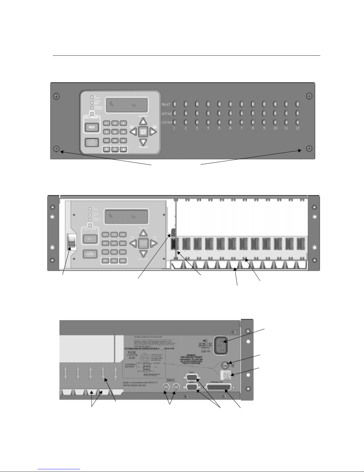
Model 9800 Central Station Receiver Installation/Operation Manual
3.3 Overview
The 9800 is assembled at the factory. One line card is shipped with the 9800 receiver. Follow
the procedures described in Section 3.5 to install additional line cards.
Face Plate Screws
Figure 3-1 Model 9800 Front View
Main
Power Switch
Phone Line
Connector
Inserted Line Card
Line Card Guides
Phone Line Slots
Figure 3-2 Model 9800 Front View Without Front Plate Attached
AC Power
Cord Connector
Fuse
Remote Relay/
Battery Connector
Phone Line
Slots
Phone Line
Strain Relief
Tie Wrap Holders
SBUS Connectors
Serial
Ports
Parallel
Printer Port
Figure 3-3 Model 9800 Rear View
3-2 151018
Page 23
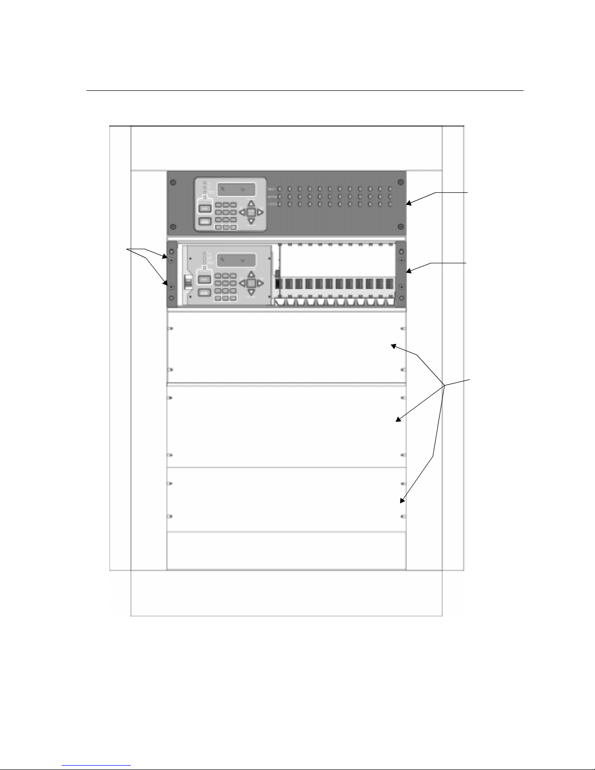
3.4 Rack Mounting
This diagram shows how to mount the model 9800 in a UL listed rack enclosure.
Receiver
Mounting
Screws
(Flat Head
supplied with
receiver)
Installation
Model 9800
Receiver
Back-Up
Model 9800
Receiver
(Shown With
Face Plate
Removed)
Figure 3-4 Rack Mount Enclosure, Front View
Note: All wiring that exits cabinet must be in electrical conduit.
Blank
(Filler)
Panels
151018 3-3
Page 24
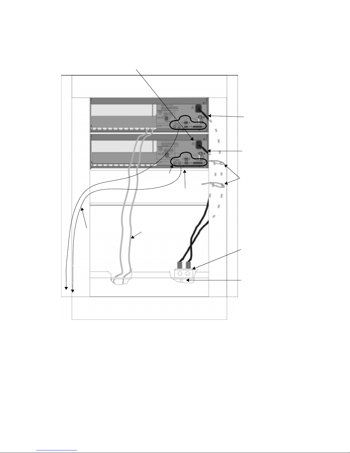
Model 9800 Central Station Receiver Installation/Operation Manual
Power/Non-power limited and
High/low Voltage Wiring
Lines Must be Separated by
1/4” Spacing
Model 9800
Receiver
Model 9800
(Backup)
Power limited
wires for SBUS
and Com ports.
Tie wrap wire
to the enclosure
Low Voltage
Power Limited
Shelf or
Support Bracket
(Under Each Unit)
Incoming
Telephone
Lines
Rear Cabinet
Door
(Not Shown)
Figure 3-5 Rack Mount Enclosure, Rear View
Tie-wrap groups
of wires to the
enclosure
Listed Receptacle
(Rated 15A 125VAC)
Incoming Line
Power 120VAC, 60Hz
Note: All wiring that exits cabinet must be in electrical conduit.
3-4 151018
Page 25
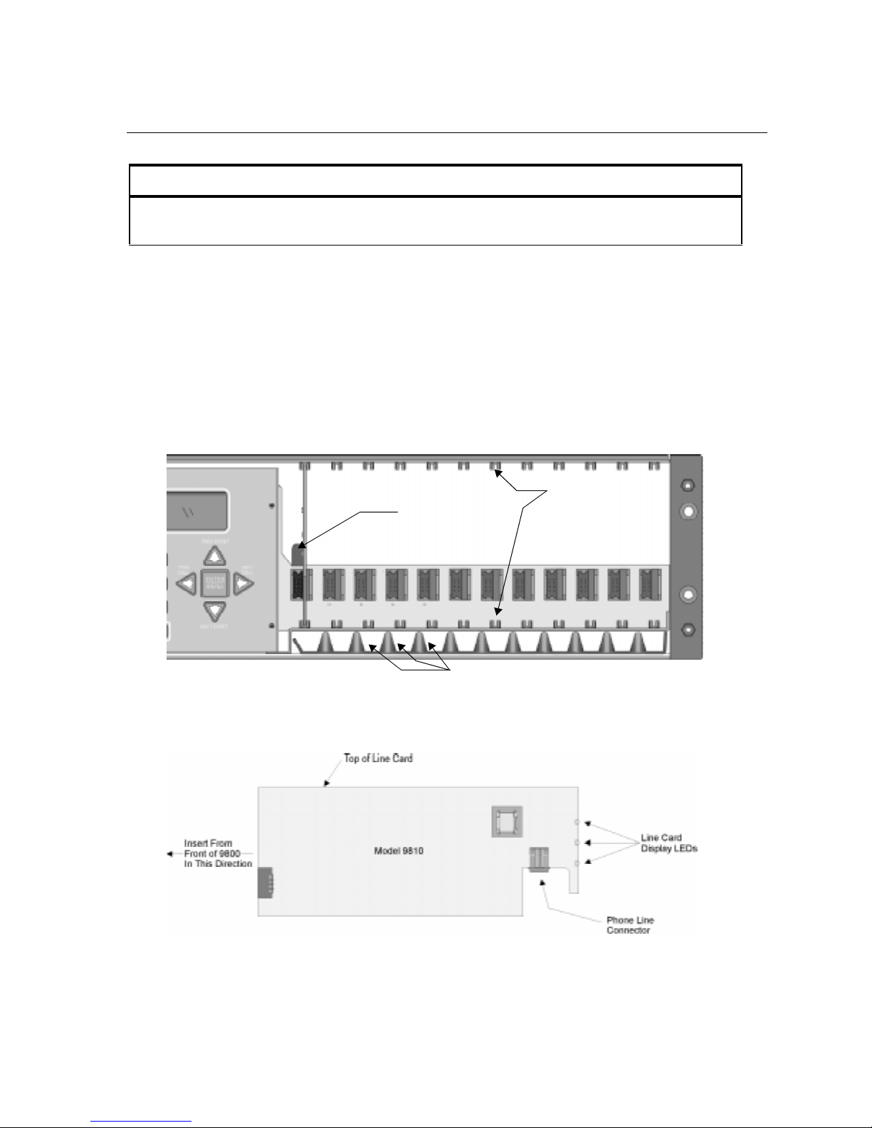
Installation
3.5 Line Card Installation
Caution:
To reduce the risk of electrical shock and damage to the receiver, follow these steps
in the order they are listed here.
1. Open the 9800's front panel by unscrewing the four front plate retaining screws located on
the front of the panel. (See Figure 3-1 for front plate retaining screw locations.)
2. Turn off the 9800’s AC power switch (see Figure 3-2 for power switch location).
3. When the front panel is removed, you will see that there are 12 slots for line cards. The
receiver recognizes each slot by number 1 through 12 (slot one is closest to the keypad and
display). It is not necessary to put line cards in numbered order because the receiver continually polls each slot to see if existing line cards are functioning and if it is still in its
slot. The receiver also looks to see if a new line card has been added. Figure 3-6 shows
where each line card should be placed.
Phone Line
Connector
Phone Line Slots
Figure 3-6 Line Card Locations
4. Position the line card as shown in Figure 3-7.
Line Card
Guides
Figure 3-7 Line Card Position and Components
151018 3-5
Page 26

Model 9800 Central Station Receiver Installation/Operation Manual
5. Carefully slide the card into its guides (both top and bottom) until it fits into its connector
at the back of the receiver. Gently push the card as far into the connector as you can. The
card is now in place.
6. Connect telephone line. (See Section 3.7 for telephone line installation.)
Note: Use the tie wrap (P/N 120101 provided with each line card) on the tie wrap holder to add strain relief to
the telephone lines. See Figure 3-3.
7. Power up the 9800.
8. Close the 9800's front panel and tighten the front plate retaining screws to hold the front
plate in place. If you are simply replacing a line card with another card of the same type
and are using the same format settings, your installation is now complete. If not continue
to the next step.
9. Enter programming mode to select the appropriate handshake configuration. (Go to
Section 5.4 for programming procedure.)
3.6 Removing Line Cards
If you need to remove a card:
1. Open the 9800's front panel by unscrewing the four front plate retaining screws located on
the front of the panel. (See Figure 3-1 for front plate retaining screw locations.)
2. Turn off the 9800’s AC power switch (see Figure 3-2 for power switch location).
3. With the front panel removed, you will see that there are 12 slots for line cards.
4. Locate the Line Card that you wish to remove.
5. Unplug the telephone line. (See Figure 3-6 and Figure 3-7.)
6. From the front side of the receiver pull the line card straight back. This will pull the card
free from the connector.
7. When the card is free, slide it carefully out of the receiver.
Note: If replacing a line card with a new one see Section 3.5 to install the new line card.
8. Power up the 9800.
9. Close the 9800's front panel and tighten the front plate retaining screws to hold the front
plate in place.
10. Enter programming mode to clear the linecard from the system.. (See Section 5.4 for programming procedure.)
3-6 151018
Page 27

Installation
3.7 Telephone Line Connection
See Figure 3-6 for the location of the phone line inputs. Connections to the 9800 phone jacks
are made with a standard 7-foot phone cord (provided with each line card).
Use the following procedure to connect phone lines to the 9810 line cards:
1. Remove the front panel of the 9800 receiver by loosening the front plate retaining screws.
(See Figure 3-1 for front plate retaining screws locations.)
2. From the back side of the receiver insert the telephone line through the corresponding slot
for the desired line card. (See Figure 3-6 and Figure 3-7 for phone line slot locations.)
3. Gently push it all the way through to the front side of the receiver.
4. Plug the RJ-11 phone connector into the connector on the 9810 line card. (See Figure 3-6
and Figure 3-7.)
Note: Use the tie wrap (P/N 120101 provided with each line card) on the tie wrap holder to add strain relief to
the telephone lines. See Figure 3-3.
5. Replace the front panel of the 9800 receiver by tightening the front plate retaining screws.
(See Figure 3-1 for front plate retaining screws locations.)
3.8 Parallel Printer Connection
The 9800 Receiver connects to model SK320 printer for UL applications. To connect the
SK320 to the 9800 receiver follow these steps:
1. Connect the standard parallel printer cable to the parallel printer port on the back of the
9800 receiver. (See Figure 3-8.)
Figure 3-8 Parallel Printer Cable Connection to 9800
2. Connect the other end to the SK320 parallel printer port.
Note: Make sure that printer power is turned off.
3. Turn the printer power “on”.
151018 3-7
Page 28

Model 9800 Central Station Receiver Installation/Operation Manual
3.8.1 Printer Cable Pin-Outs
25 pin printer cables are a standard items at most electronic stores, however , if you create your
own cable, use the pin description in Table 3-1.
Table 3-1: External Printer Cable Pin Description
9800 Pin # Signal Direction Description
1 Data Strobe (Low) Out A low strobe pulse to read data in the
pulse width is greater than 0.5
microseconds.
2 Data Bit 1 Out These signals represent information
3 Data Bit 2 Out
4 Data Bit 3 Out
5 Data Bit 4 Out
6 Data Bit 5 Out
7 Data Bit 6 Out
of the first to eighth bits of parallel
data. Each signal is at high level
when the data is logic 1 and low
when it is logic 0.
8 Data Bit 7 Out
9 Data Bit 8 Out
10 /AckNlg In A low pulse from the printer signals
the control that the printer is ready for
additional data.
11 Bu sy In A high level indicates that the printer
is busy.
12 Pa p er Empty In A high level indicates that the printer
is out of paper.
13 Select In A low level indicates the printer is
offline or in an error condition.
14 Not used - 15 Not used - 16 Logic ground - Logic ground for printer
17 Not used - 18 to 25 Logic Ground - Ground return for data lines.
3-8 151018
Page 29
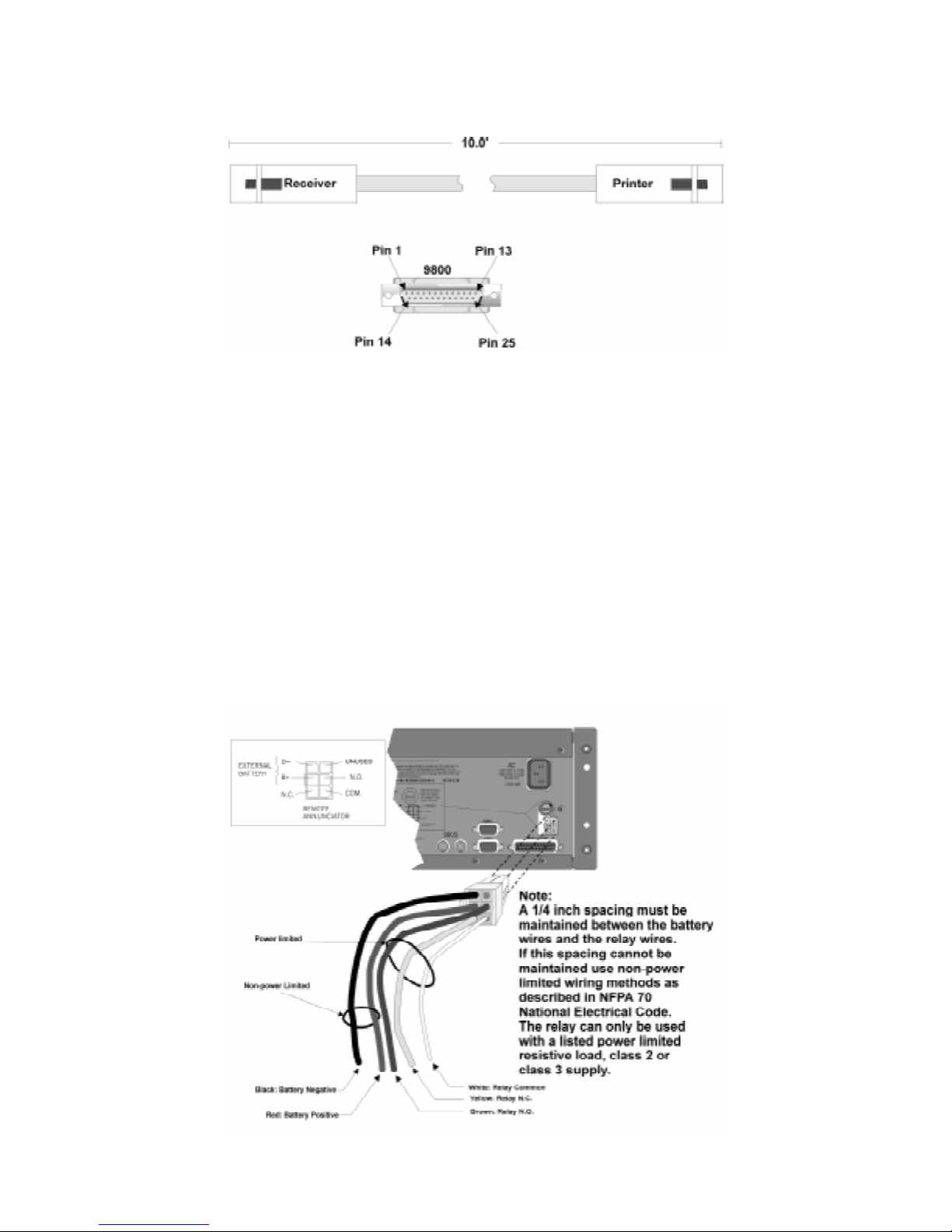
Installation
Figure 3-9 shows the wiring sequence of this connector.
Figure 3-9 Wiring Sequence For Parallel Printer Port Interface
3.8.2 Com Ports 1 & 2
Com ports one and two are serial communication ports that (through a null modem cable) can
be used to communicate to other serial communication devices. Com port one is the only
serial communications port that can be used with the automation com puter (s ee Section 3.11).
A standard null modem cable can be used to connect com port 1 or 2 to another serial device
such as a printer or a PC. Figure 3-15 and Figure 3-16 shown the pin-outs for a null modem
cable. See Section 5.3.3 to configure the Com Port 1 and Com Port 2.
3.8.3 Remote Alert Output
1. Plug the Battery/Relay wiring harness onto the connector on the back of the 9800 receiver.
(See Figure 3-10.)
Note: The remote alert output is a form C relay with a normally open or a normally closed wire.
Figure 3-10 9800 Remote Alert Output/Backup Battery Connection
151018 3-9
Page 30

Model 9800 Central Station Receiver Installation/Operation Manual
2. Connect the white wire to common.
3. Use the Yellow wire for a normally closed circuit
Or
Use the Brown wire for a normally open circuit.
3.9 AC Power Cord Connection
1. Before the AC power cord is connected, make sure that the power switch is in the OFF
(down) position.
2. Connect the appropriate end of the power cord into its receptacle on the back of the 9800.
3. Plug the three-pronged end of the power cord into a 120 VAC 60 Hz outlet (three-prong
type only). The outlet should be unswitched, so that power remains on 24 hours a day. The
outlet must also be earth grounded. Follow the directions in Section 3.9.2 if you need to
measure for proper earth grounding.
3.9.1 Switching to a 230 VAC Power Supply
1. Remove the front plate by unscrewing the front plate retaining screws. (See Figure 3-1 for
locations of front plate retaining screws.)
2. Turn the main power switch to the “off” position. (See Figure 3-12.)
3. Disconnect AC power cable.
4. Disconnect the backup battery. (See Figure 3-14.)
5. On the back of the receiver remove the four screws that hold the mother board/power supply assembly to the chassis. (See Figure 3-11 for screw locations.)
Screw
Locations
Figure 3-11 Mother Board/Power Supply Assembly Retaining Screw Locations
6. From the front of the receiver pull the mother board/power supply assembly out.
3-10 151018
Page 31

Installation
7. Switch the power supply select switch to the up position. The switch will show 230VAC.
(See Figure 3-12.)
On
Off
Figure 3-12 Side View of Mother Board/Power Supply Assembly
8. Slide the mother board/power supply assembly back into the receiver chassis.
9. On the back of the receiver replace the four screws that hold the mother board/power
supply assembly in place. (See Figure 3-11.)
10. Reconnect the AC power cable.
Note: Make sure to plug the AC power cable into a grounded 240VAC outlet.
11. Reconnect the back-up battery. (See Figure 3-14.)
12. Turn the main power switch to the “on” position. (See Figure 3-12.)
13. Replace the front plate by screwing in the front plate retaining screws. (See Figure 3-1.)
151018 3-11
Page 32

Model 9800 Central Station Receiver Installation/Operation Manual
3.9.2 How to Verify Earth Ground
To verify earth ground at the AC outlet the 9800 receiver is powered from, use the following
steps:
1. Measure the AC voltage between the center ground post and each side of the outlet (see A
& B in Figure 3-13). You should read approximately 120 VAC (or 240VAC for 240VAC
circuits) at measurement point B and nominal VAC at measurement point A.
Figure 3-13 Outlet Voltage Measurement Points
2. Measure the voltage between the two slotted holes. It should be equal to the voltage reading at measurement point B. (See Figure 3-13.)
If these voltages are not equal, the outlet does not have a proper earth ground.
3. Ground the outlet by running a wire (18 gauge or higher) to a good earth ground.
The wire should be of equal or greater diameter to the wires used to feed the outlet. It may be
necessary to have a licensed electrician ground the outlet.
3-12 151018
Page 33

Installation
3.10 Battery Connection
To install the 6712 backup battery follow these steps:
Note: The 6712 (12VDC 7ah battery) will provide a minimum of 4 hours of battery backup power. (See 2.3.2 for
UL requirements.)
1. Plug the Battery/Relay wiring harness onto the connector on the back of the 9800 receiver.
(See Figure 3-14.)
2. Connect the RED terminal to the positive (+) side of the battery.
3. Connect the BLACK terminal to the negative (-) side of the battery.
Note: Incorrect polarity can damage the battery and the 9800.
151018 3-13
Figure 3-14 Battery Connections
Page 34

Model 9800 Central Station Receiver Installation/Operation Manual
3.11 Automation Computer Connection
An automation computer can be connected to Com Port 1 on the 9800 receiver. Com Port 1 is
a 9-pin DTE port. Refer to Section 8 for details on automation communication protocols. The
diagrams below describe some of the cable options.
Figure 3-15 25-Pin Null Modem Cable Connection
Figure 3-16 9-Pin Null Modem Cable Connection
3.11.1 Computer Port Baud Rate Selection
The computer port baud rate is selectable from 110 to 19200 (See Section 5 Programming).
3-14 151018
Page 35

Section 4
Operation
This section covers information on how to operate the 9800 Receiver.
4.1 Touchpad Function Buttons
The front panel of the 9800 is made up of; a touchpad, containing numbers, arrows and
buttons; a LCD display; and an array of LED indicators. (See Figure 4-1.)
LED Display
s
Touchpad
Keys
Figure 4-1 Model 9800 Front Panel
LCD Display
The touchpad on the 9800 Receiver is used in all operating modes (normal and programming
mode).
151018 4-1
Figure 4-2 Touchpad Layout
Page 36

Model 9800 Central Station Receiver Installation/Operation Manual
Table 4-1 displays each individual touchpad key and describes its function in each operating
mode.
Table 4-1: Touchpad Buttons Description
Operating Modes
Key Name
Up Arrow Display previous event. Go back to previous choice or
Down Arrow Display next eve nt. Move to next choice or
Left Arrow Display previous call. Exit the current menu. Move to
Right Arrow Display next call. Select menu item indicated by
Enter/Menu Button Bring up Main Menu. S elect menu item indicated by
Normal Programming
character.
character.
previous programming field.
equal sign (see Figure 4-6).
Move to next programming
field.
equal sign (see Figure 4-6).
Enter chosen parameter.
Acknowledge Button Manually Acknowledge a
call or event. (Used only if
receiver is in manual
mode.)
Log Button Pressed to log o n or off the
system. Pressed to view
system status messages.
Digit Keys Used to enter numeric
Star or Home Key Will return display to the
0 or Hangup key In manual mode the 0/
Pound Key or Listen
Key
inputs.
oldest unacknowledged
event.
hangup key is used to
hangup line card when the
listen feature was
activated, or to end a
runaway call from a panel.
In manual mode this key is
used to initiate the listen in
feature.
Used in log mode to
acknowledge and silence
system troubles.
N/A
Numeric input, option
selection.
Character when
Enters a
programming in an “Edit” field.
See T a ble 5-1 for Types of
Programming Fields,
descriptions.
Used to enter numeric inputs.
Enters a
programming in an “Edit” field.
See T a ble 5-1 for Types of
Programming Fields,
descriptions.
Character when
4-2 151018
Page 37

4.2 Displays
This section describes the two types of displays that the 9800 receiver uses.
4.2.1 LED Displays
Table 4-2: LED Description
Operation
Touchpad
LEDs
Line Card
LEDs
LED
On Off Flashing
AC Power AC power is on. No AC or DC power to
System Fault A fault condition exists
that has been
acknowledged but not
cleared.
Operator Logged In An operator is logged on. No operator is logged
Call Pending The acknowledge key
was pressed at least once,
but not all the events in a
call were acknowledged.
Fault N/A The line card is
Active The line card is in active
communication.
Listen Comes on when operator
acknowledges the listenin call.
Meaning
the Receiver
The system is operating
normally.
on.
No calls pending or all
calls have been
acknowledged.
operating normally.
No Activity. Indicates the line is
No listen-in occur ring. N/A
No AC power and the
system is operating o n
the backup battery.
A fault condition exists
that has not been
acknowledged.
Calls pending.
Troubl e or fau lt
condition exists.
ringing.
4.2.2 LCD Status Display
The status display is a 4-line 20 character (each line) back-lit LCD that shows the various
alarm and function messages. It functions in all modes of operation (normal and programming
mode). As the 9800 acknowledges calls and messages, it updates the calls on the LCD and
silences the alert tone.
151018 4-3
Figure 4-3 LCD Display
Page 38

Model 9800 Central Station Receiver Installation/Operation Manual
4.2.2.1 Adjusting LCD Contrast
The LCD is factory set at the highest contrast level and for most installations will not need to
be adjusted. Use these steps to change the LCD contrast if the brightness of the room or the
location in which the receiver is located should require a contrast change:
1. Press and hold both the up arrow and the left arrow keys at the same time. (See
Figure 4-4.)
Figure 4-4 Contrast Adjustment
2. Release the up and left arrow keys when you reach the desired contrast level.
4-4 151018
Page 39

Operation
4.2.2.2 LCD Abbreviations
Many of the words used on the LCD are abbreviated to accommodate 20 characters per line.
Table 4-3 compares the event that is reported to how it is output to the LCD and printer.
Table 4-3: LCD and Printer Abbreviations
Event LCD Printer
Alarm Alrm Alarm
Trouble Trbl Trouble
Restore Rstr Restore
Supervisory Sprv Superv
Opening Open Opening
Closing Clos Close
Remote Rmot Remote
Disable Dsbl Disable
Bypass Byps Bypass
Unbypass Ubyp Unbypass
Test Te st Test
Listen-in Lstn Listen
System Sytm System
Access Accs Access
Report Rprt Report
Cancel Cncl Cancel
Zone Number Z# Zone
Door Number D# Door
User Number Us# User
Area Number A# Area
151018 4-5
Page 40

Model 9800 Central Station Receiver Installation/Operation Manual
4.3 Initial System Power Up
Apply power to the 9800 by plugging in the AC power cable and then turning the main power
switch “on”. (See Figure 3-2 and Figure 3-3.)When the 9800 powers up, the display will go
through the routine shown in Figure 4-5.
The system defaults in the manual operation. To select automatic operation see Section
5.3.1.1.
Note: Any time the main power switch is turned off the time and date will have to be reprogrammed on power-up.
4-6 151018
Figure 4-5 Power-up Routine
Page 41

Operation
4.4 Log On / Log Off
Persons operating the 9800 must log on and off the system. This is a way of keeping track of
whom is operating the system at any given time.You can program a total of 40 codes. Each
code will be assigned to one of two user profiles (Installer profile or Operator profile). (See
Section 4.4.3 for default user codes.)
4.4.1 Installer Profile
The Installer profile will have access to all options on the main menu (see T able 4-4 for “Main
Menu” options).
4.4.2 Operator Profile
The Operator profile has access to fewer main menu options than the Installer profile (see
Table 4-4). These options allow the operator to perform basic operation of the 9800. Both
profiles can acknowledge all calls and events.
Table 4-4: Main Menu Option Items by Profile
Installer
Profile
Note: See Section 4.6 for detailed information on the main menu options.
Operator
Profile
Menu Options
Call History
System History
System Info
Set Time & Date
System Restart
Printer Menu
Program Menu
Diagnostics
You must have at least one Installer Profile Code programmed in the system at all times.
151018 4-7
Page 42

Model 9800 Central Station Receiver Installation/Operation Manual
4.4.3 Default User Codes
At initial power up, the system provides two default user codes. User code 1 defaults with an
Installer profile and user code 2 defaults with an Operator profile. Table 4-5 shows the default
codes and their profiles.
Table 4-5: Default User Codes
User Number
*1 9800 Installer
2 1111 Operator
* Note: User code 1 can be changed but not deleted. User code 1’s profile will alway s remain as “installe r”.
Default Code
(PIN)
Default Profile
4.4.4 How to log on the system.
Follows these steps to properly log on to the system:
1. Press the button.
The LCD will display (QWHU/RJ,Q&RGH
>@
2. Enter your PIN code. (See Table 4-5 for default codes.)
Note: This screen will tim e out after 15 seconds.
3. Press the button.
If the correct PIN is entered the LCD will display ,QVWDOOHU;;
8VHU1DPH.
The “Operator Logged In” LED will also turn on.
If an invalid code is entered the LCD will display $FFHVVFRGHQRWYHULILHG.
Note: If the previous user has not logged off, a new user can still log on by entering a PIN code. This will
automatically log off the previous u ser and log in the new user.
4-8 151018
Page 43

Operation
4.4.5 How to log off the system.
Follows these steps to properly log off the system:
1. Press the button.
The LCD will display QQ8VHU1DPH
/RJ2XW
>@
Note: This screen will tim e out after 15 seconds.
2. Enter your PIN code. (See Table 4-5 for default codes.)
3. Press the button.
If the correct PIN is entered the LCD will display 8VHU1DPH/RJJHGRXW . The “Op er-
ator Logged In” LED will also turn off.
If an invalid code is entered the LCD will display $FFHVVFRGHQRWYHULILHG.
151018 4-9
Page 44

Model 9800 Central Station Receiver Installation/Operation Manual
4.5 Modes of Operation
This section describes the different modes of operation for the 9800 Receiver (normal mode
and programming mode) and the options available in them.
4.5.1 Normal Mode
Normal mode consists of three options, one if the receiver is intended to be used with a
automation system, one for manual operation, and one to just log the events without manual
acknowledgments or automation communication.
4.5.1.1 Manual Operation
Requires a manual acknowledgment of each call or event from an operator.
How to Manually Acknowledge Calls:
When a the call pending LED is flashing and the on-board annunciator is beeping:
1. Press the button to acknowledge the call.
2. Repeat step 1 until all calls are acknowledged and the display shows 1R0RUH'DWD.
4.5.1.2 Automatic Operation
Event information is sent directly to the automation computer.
Note: If the automation system fails, the receiver will automatically switch to manual mode in less than 30
seconds. The switching time is twice the value set in Ack Timeout (See Table 5-5). The receiver will return
to automatic mode after communication to the automation computer is restored.
4.5.1.3 Log Only
Log only mode will log event data without manual acknowledgments or communications wit h
the automation computer. All event information is intended for printer output.
Note: On initial power-up the receiver will default in manual operation. The receiver can be set to automatic or
log only operation in program mode (see Section 5. 3.1).
4.5.2 Program Mode
In program mode all general, line card, and user profile options can be changed. See Section 5
Programming
Quick Chart (, Table A-1) for programming overview.
for more detailed information on programming the receiver or refer to the
4-10 151018
Page 45

Operation
4.6 Main Menu
This section gives detailed information about the items available in the Installer/operator
menu options, which this manual will refer to as the main menu. The menu items available to
each logged on user is dependent on the profile assigned to that user
(see Table 4-4 for menu items for each profile). The user profile is assigned to each user
through programming (see Section 5.5 for programming user profiles).
4.6.1 How to display the Main Menu
Once a user has logged on to the system (see Section 4.4.4), follow these steps to view the
main menu options:
1. Press the button.
The LCD display will show the main menu options.
Note: The main menu display will remain visible for 15 minutes of idle time after which it will revert back to the
manual or automatic display window. See Figure 4-3.
2. Choose the desired menu item. (See Figure 4-7.)
151018 4-11
Figure 4-6 Main Menu Display
Page 46

Model 9800 Central Station Receiver Installation/Operation Manual
4.6.2 How to Maneuver Through Main Menu
Figure 4-7 indicates what keys on the touchpad are used to maneuver through the Main Menu.
Figure 4-7 Main Menu Controls
4-12 151018
Page 47

4.6.3 Call History
Call history displays the calls that are in the history buffer.
Operation
Event Reference
No. (0001-9999)
Reason for Call
Zone Number
Month &
Day
Line Card No.
Time
Account Number
(Up to Eight Digits)
Number and order
of events for this
report
Star indicates that
the call was acknowledged
Figure 4-8 View of a Call History Screen
Note: The Letter preceding the linecard number may appear as a “G” if the linecard the call came in on is
programmed for a hunt group. See “Misc. Line Opt.” in Section 5.4.2.5.
To display a specific event enter the reference number then press the . Press the
to go to most recent call. See Table 4-3 for display abbreviations.
4.6.4 System History
System history displays any events that are stored in the history buf fer. Syst em events are any
events related to the receiver operation such as line card faults, low backup battery, AC power
loss, log in, log out, system program change, communication failure to a printer or automation
system, etc.
Event Number
View after
2 pressed
Up arrow
displays previous
event
Figure 4-9 System History Display Sequence
Note: Up arrow moves back to the previous event that occurred.
To display a specific event enter the event number (see Figure 4-9) then press the . Press
the to go to most recent call.
151018 4-13
Page 48

Model 9800 Central Station Receiver Installation/Operation Manual
4.6.5 System Info
System Info is a non-editable screen that displays the model number, the software revision,
software date code, receiver ID number. If a down arrow is pressed, the display will show the
line card firmware information, which includes the model number, the software revision, the
software date code, and letter revision.
Version Number
Model Number
Date Code
Firmware
Letter Rev.
Figure 4-10 System Information Display
Part Number
4-14 151018
Page 49

Operation
4.6.6
If Set Time & Date, is selected the operator can change the time and date currently displayed
on the receiver. (See Figure 4-11 for setting time and date procedure.)
Set Time & Date
Figure 4-11 Setting Time and Date Program Sequence
151018 4-15
Page 50

Model 9800 Central Station Receiver Installation/Operation Manual
4.6.7 System Restart
System restart allows the operator or installer to restart the receiver. An installer has the
option to set the receiver back to factory default settings, while an operator can only restart the
receiver.
Note: The time and date set in the receiver will be saved. However, all of the call history will be lost
Figure 4-12 System Restart Display
Follow These Steps to restart the receiver:
Note: All messages must be acknowledged before a system restart procedure can be performed. If all messages
are not acknowledged, cycle the receiver’s power to restart the system. If the power is cycled all
unacknowledged messages will be lost.
1. Log on to the receiver (see Section 4.4.4 for log on procedure).
2. Press the button to view the main menu items.
3. Press for 6\VWHP5HVWDUW.
The display reads 'R\RXZLVKWR
VKXWGRZQUHVWDUW
V\VWHP"1R
4. Press the or button to toggle 1R to <HV.
5. Press . Users with an operator profile are done at this point.
The display reads 'R\RXZLVKWRVHW
WRIDFWRU\GHIDXOW
VHWWLQJV"1R
Note: This display will only appear if the logged on User has an Installer Profile (see section 4.4.1).
6. Press the or button to toggle between 1R and <HV.
Note: If you choose Yes all linecard and user custom programming will be lost.
4-16 151018
Page 51

Operation
4.6.8 Printer Menu
In the print menu you can print customized reports by the type of alarm (as defined by UL
864, Section 72.15F), edit the desired print output, configure output for your printer.
Figure 4-13 Print Menu Items
Table 4-6: Printer Menu Choices
Printer Menu Choice 1 Choice 2 Comments
Print Report
Edit Evnt Format
Config Printer
Priority 1
(Life safety signals-Fire, Duress)
Priority 2
(Property safety signals-Burg.)
Call History
System History
System Config
Test Page Print a test page.
Date Y or N Y Indicates that this item will print on a report.
Format Type Y or N
Ref Number Y or N
Call Sep Y or N
Device Num Y or N
Line
Terminator
Offline Time
Switch Delay
Time
Priority 3
(Supervisory signals)
Priority 4
(Trouble signals)
Priority 5
(All other signals)
Print All Print all of the receiver and line card data.
Program Data Print just the systems programmed data.
Line Card # Print line card config ur a tio ns pe r line ca rd.
CR or CRLF CR = Carriage return.
0 - 60 seconds Offline time is how long the receiver will wait
0 - 60 seconds Switch delay time is the duration the receiver will
Y Indicates that this item will print on this
report.
N Indicates that this item will not print on this
report.
The call History print will execu te once you exit
from “Choice 2”.
Note:
Choice 2 settings are n ot re ta ined in fl ash
memory and have to be chosen for each
call history printing .
This option prints all the system events in the
event history buffer.
N Indicates that this item will not print on a
report.
Default setting is Y for all edit event format
options.
These settings are saved to flash memory.
CRLF = Carriage return and Line feed.
before giving a trouble indication af ter
communication is lost with the printer. The
default setting is 2 seconds. (30 second maxim um
for UL applications.)
wait before switching to the backup printer after
communication is lost with the primary printer.
The default setting is 20 seconds.
151018 4-17
Page 52

Model 9800 Central Station Receiver Installation/Operation Manual
4.6.8.1 Print Report
Through the print report option you can choose to print the call history , system history, system
configuration information, or just print a test page.
Figure 4-14 Print Report Menu Items
How to Print Call History
Follow these steps to print the call history:
1. Log on to the receiver (see Section 4.4.4 for log on procedure).
2. Press the button to view the main menu items.
3. Press for the printer menu. (See Figure 4-13.)
4. Press for print report menu. (See Figure 4-14.)
5. Press for call history options.
4-18 151018
Figure 4-15 Call History Options
Page 53

Operation
6. Press the or button to move through the call history menu choices. See Figure
4-15.
7. When the equal sign highlights the call history items you desire to print for this report
press or to toggle the setting between Y (yes print) or N (don’t print).
8. Press to exit menu.
How to Print System History
Follow these steps to print the system history:
1. Log on to the receiver (see Section 4.4.4 for log on procedure).
2. Press the button to view the main menu items.
3. Press for the printer menu. (See Figure 4-13.)
4. Press for print report menu. (See Figure 4-14.)
5. Press to print the system history.
6. Press to exit menu.
151018 4-19
Page 54

Model 9800 Central Station Receiver Installation/Operation Manual
How to Print System Configuration
Follow these steps to print the system configuration:
1. Log on to the receiver (see Section 4.4.4 for log on procedure).
2. Press the button to view the main menu items.
3. Press for the printer menu. (See Figure 4-13.)
4. Press for print report menu. (See Figure 4-14.)
5. Press to view system configuration options. See Figure 4-16.
Figure 4-16 System Configuration Print Items
6. Press the or button to move through the system configuration print choices.
7. When the equal sign highlights an option press or to toggle the setting
between Y (yes print) or N (don’t print).
8. Press to print the data and exit menu.
Note: These choices are not saved to flash memory and will have to be chosen each time that pri nt s ystem
configuration is entered.
4-20 151018
Page 55

How to Print a Test Page
Follow these steps to print a test page:
1. Log on to the receiver (see Section 4.4.4 for log on procedure).
2. Press the button to view the main menu items.
Operation
3. Press for the printer menu. (See Figure 4-13.)
4. Press for print report menu. (See Figure 4-14.)
5. Press to print a test page.
6. Press to exit menu.
4.6.8.2 Edit Event Format
Edit event format allows you to configure what information will print on reports to the
receiver.
Follow these steps to configure the report format:
1. Log on to the receiver (see Section 4.4.4 for log on procedure).
2. Press the button to view the main menu items.
3. Press for the printer menu. (See Figure 4-13.)
4. Press for event format menu items. (See Figure 4-17.)
151018 4-21
Figure 4-17 Event Format Menu Items
Page 56

Model 9800 Central Station Receiver Installation/Operation Manual
5. Press the or button to move through the event format choices. (See Table 4-6
for choice definitions)
Table 4-7: Event Format Choices and Meaning
Event Format
Options
Date/Time
Format Type
Reference
Number
Call Separator
Device Number
Choices Meaning
Y (Yes) Y = date and time will print for each report message to the printer.
N (No)
Y (Yes) Y = The reporting format type of the calling control panel will print for each
N (No)
Y (Yes) Y = The reference number will print for each report message to the printer.
N (No)
Y (Yes) Y = Print a dashed-line between each messa ge report to the printer.
N (No)
Y (Yes) Y = Print the device number of the reporting message to the printer.
N (No)
N = Date and time will not print for each report message to the printer.
report message to the printer.
N = The reporting format type of the calling control panel will not print for
each report message to the printer.
Note:
The Format Type will be listed as a number, which represents the
format used for that communication. See
N = the reference number will not print for each report message to the printer.
(See Figure 4-8)
N = Do not print a dashed-line between each message report to the printer.
N = Do not print the device number of the reporting message to the printer.
6. When the equal sign highlights each option press or to toggle the setting
between Y (yes print) or N (don’t print).
Note: These settings are saved to flash memory.
7. Press to exit menu.
4-22 151018
Page 57

Operation
4.6.8.3 Configure Printer
Depending on the printer you are using it may require that this be set to either carriage return
or carriage return with a line feed.
Follow these steps to configure the printer:
1. Log on to the receiver (see Section 4.4.4 for log on procedure).
2. Press the button to view the main menu items.
3. Press for the printer menu. (See Figure 4-13.)
4. Press for configure printer menu items.
The display will be flashing on the line terminator field.
5. Press the or button to toggle between CR or CRLF. (See Table 4-6.)
6. When the desired setting is flashing press .
The display will now flash on the offline time field.
7. Enter the desired time (from 01-99 seconds), 30 second maximum in UL applications.
8. Press .
The display will now flash on the switch delay time field.
9. Enter the desired time (from 01-99 seconds).
10. Press .
11. Press to exit menu.
151018 4-23
Page 58

Model 9800 Central Station Receiver Installation/Operation Manual
4.6.9 Program Menu
If program is selected from the main menu the system will enter into “Program Mode”. (See
Section 4.5 for information on modes of operation.) In program mode you can program all the
general options, line card options, and user list. (See Appendix A, Table A-1 for programming
Quick Chart.)
Figure 4-18 Program Menu Items
4.6.10 Diagnostics Menu
The diagnostics menu items can be used while testing and troubleshooting the system.
Figure 4-19 Diagnostics Menu Items
4-24 151018
Page 59

Operation
4.6.10.1 Phantom Menu
The phantom menu contains list of various communication format phantom signals (see Table
4-8) that can be used to test the receiver or automation software configurations. For example,
you set a linecard parameters for a particular communications format and would know like to
verify that this new configuration will communicate with other communication formats, you
can send phantom signals in the formats you wish to test that linecard with.
Table 4-8: Phantom Signals Formats List
Choice Format
'&6
&,'
,7,
%)6.
$ 7DVN
$ &KHFNVXP
$
$
)6.
)6.
)6.
6,$ '
$'0 &KHFNVXP
6,$ ' &KHFNVXP
$&521 728&+ 721(
$'0 &KHFNVXP
)%,
DCS
Contact ID
ITI format
BFSK
3/1 format
3/1 format w/checksum
4/1 format
4/2 format
FSK0
FSK1
FSK2
SIA D1
Ademco 4/2 format w/
checksum
SIA D1 w/checksum
Acron Touch Tone
Ademco 4/1 format w/
checksum
FBI 4+3+1
151018 4-25
Page 60

Model 9800 Central Station Receiver Installation/Operation Manual
4.6.10.2 Message Que
Message Que gives a visual indication of how full is the message queue. It does this with both
a percentage indication and a bar graph (made of ’s). Each is approximately 5%.
Figure 4-20 Message Queue Level
4.6.10.3 Event Log
Print Log allows you to print out a certain range of reference numbers to the port designated to
diagnostics. This can be used to as a troubleshooting tool while correlating alarm messages
from the receiver to the automation computer.
Enter the reference
number you wish to
start at here.
And the range of
event here.
Figure 4-21 Event Log Display
For example, if the automation computer indicated a report that you are not familiar with, you
would enter the reference number for that report in the event log and the raw data would be
output to the diagnostic port. From the raw data you could determine what the signal was and
make adjustment to the automation computer for future signals like that one.
4-26 151018
Page 61

Operation
4.6.10.4 Format
Format designates the type of output you wish for the Event Log report. The output format can
be in raw ASCII, a printer format, or one of the receivers automation communication formats
(see Section 8 for automation protocols).
Information after the dash
indicated the format
presently chosen.
Figure 4-22 Diagnostic Formats
4.6.10.5 LC Debug Mode
LC debug enables the receiver to generate detailed history of handshake sequences to the call
buffer. This information can be used for troubleshooting.
Select Line Card
Numbers
Figure 4-23 Select LC Debug Mode by Line Card
Use the right arrow or to toggle the line card selection between “Yes” or “No”.
Press to exit and “Yes” to save changes.
151018 4-27
Page 62

Model 9800 Central Station Receiver Installation/Operation Manual
4.7 Listen-In and Hang Up
Note: See Section 2.3.2 for UL requirement on listen-in.
This section explains how to operate the receiver for listen-in calls. Some panels that perform
listen-in send a listen-in indicator included in the reported message to the receiver. Any panel
that does not send this message must be added to the Listen-In Account List (see Section
5.4.2.3).
When a listen-in call is received by the 9800, the LCD display will indicate the account
number and (depending on the panel) the listen-in timeout period. The listen-in LED on the
linecard will be illuminated to confirm the line card indication.
4.7.1 Manual (Common) Listen-In Operation
Follow these steps to manually handle the listen call:
1. Press .
2. Enter the line card number.
3. Pick up the telephone the listen-in call is on. See Figure 4-24 for a diagram of how the listen-in phone should be connected (in parallel) with the phone line of the line card.
Figure 4-24 Phone Connector Pin-Out and Listen-in Wiring Diagram
4. Perform the listen-in procedures for that panel (refer to panel operation manual).
4-28 151018
Page 63

Operation
4.7.2 PBX Operation
Prior to performing listen-in functions on a PBX phone line system the receiver must be set up
with the proper listen-in mode and PBX string. Refer to Sections 5.1 and 5.4.2.3 to properly
program the receiver to handle PBX listen-in calls.
4.8 Testing the System
IMPORTANT:
The 9800 should be tested regularly to ensure complete and proper operation.
Because there are so many variations in dialer parameters and phone line conditions, the only
way to be absolutely certain that all subscribers can communicate with the 9800 is to test
every subscriber's dialer individually. Subscribers must test their communicators every 30
days to make sure the 9800 receives the information.
When you install a new 9800, test every manufacturers' panels for each format. This is
necessary because different manufacturers' panels may operate differently even if all panels
use the same format.
151018 4-29
Page 64

Model 9800 Central Station Receiver Installation/Operation Manual
4-30 151018
Page 65

Section 5
g
Programmin
This section lists the programmable features in programming mode and the procedures for
each of them. The options available are general options, line card options, and user options.
5.1 How to Enter Program Mode
Follow these steps to enter into program mode:
1. Log on to the receiver (see Section 4.4.4 for log on procedure).
2. Press the button.
3. Press the button.
The display will briefly display,QLWLDOL]LQJ
3OHDVHZDLW
4. Select the option you wish to program. (See Section 5.2 for options.)
5.1.1 Programming Fields
In program mode there are three types of programming fields that data can be entered into.
Table 5-1 list the three types of fields and the various parameters associated with them.
Table 5-1: Types of Programming Fields
Type of Field Control Keys Comments
These fiel ds require a numeric entry
only.
Predefined choices are put in a list and
can be selected by pressing the up or
down arrow keys.
Numeric
List
through
or keys
keys
Edit
151018 5-1
through
or keys
Enter a number from the numeric
keypad or enter any special characters
by pressing the up or down arrow keys.
Page 66

Model 9800 Central Station Receiver Installation/Operation Manual
5.1.2 How to Maneuver Around in Program Mode
Figure 5-1 shows what keys on the touchpad are used to maneuver in program mode.
Figure 5-1 Programming Controls
5.2 Programming Choices
In programming mode your first set of choices are general options, line card options, and user
list. (Each of these choices will be described in grea ter detail in the following sections.) Figure
5-2 shows what the display will look like before and after the down arrow is pressed.
Figure 5-2 Program Menu Choices
5-2 151018
Page 67

Programming
5.3 General Options
The features available for programming under general options are operation mode, display
options, communications, and system options.
Figure 5-3 General Options Display
151018 5-3
Page 68

Model 9800 Central Station Receiver Installation/Operation Manual
Table 5-2 list the available choices under General Options and gives a description of those
choices.
Table 5-2: General Options Items and Description
General
Options
Items
Operation Mode
Display Options
Level 1 Choices Level 2 Choices Level 3 Choices Comments
Manual
Automatic
Log Only
Language
Time Display
Date Format
Daylight Savings
Edit ITI Options
Sorted Events
Hold Last Event
English
español Not available at this time
AM/PM AM/PM is used for 12 hour time cl ock
24 Hour
M/D/Y
D·M·Y
Y-M-D
Yes See 5.3.2.4.
No
Attempts
CPU Time
CPU Type
Panel Rev
Arming Level
Yes Will sort events as defined in UL 864,
No
Yes LCD will display the last or oldest
No
Yes Affects printer output for ITI calls
No
Yes
No
Yes
No
Yes
No
Yes
No
See Section 5.3.1 for additio nal
information on Operation Modes.
See 5.3.2.1.
displays. See 5.3.2.2.
M = month, D = day, and Y = year.
See 5.3.2.3.
only.
Section 72.15F
1. Life Sa fety signals = fire, duress.
2. Property safety signals = burg.
3. Supervisory signals.
4. Trouble Signals.
5. All other signals. See 5.3.2.6.
unacknowledged event in stead of the
date/time display. See 5.3.2.7.
5-4 151018
Page 69

General
Options
Items
Communication
Programming
Table 5-2: General Options Items and Description
Level 1 Choices Level 2 Choices Level 3 Choices Comments
Com1 Unused/Automation/
Printer/
Com2 Unused/[Auto Bkp]/
[Auto Bkp Prn]/
{Print Bkp}/Diag/
Printer
MeterMinder
Port Functions
Com Port 1
Com Port 2 Same as Com Port 1 See Section 5.3.3.3.
Par Port Init String See Section 5.3.3.4.
Automation Config
Par Unused/[Auto Bkp]/
Printer/Diag
MeterMinder
Baud Rate 19200/9600/7200/
4800/2400/1200/
600/300/110
D (# Data Bits) 7, 8
S (# Stop Bits) 1, 2
P (Parity) Even, Odd, Space,
Mark, No
F (Flow Control) Hdwr, None None = no supervision
Init String See Section 5.3.3.4.
Format SIA CIS, SIA 2000,
SK 9000, SK EXP,
ITI Gen, ITIComp
Hex
Heart Beat Y = Enabled
Time (of Heartbeat) 10-600 Seconds
Ack timeout 0-600 Seconds
Y = Enabled
N = Disabled
N = Disabled
Rules for Port Configuration:
1. Functions in Brackets [ ] will not
appear unless “Automation” is
selected for Com1 function.
2. Functions in { } will not appear
unless “Printer” is selected in
Com1 or Par.
3. A function may be selected only
once in the 3 ports (only one
printer, on ly on e Diag, a nd so on ).
4. All ports may be configured
“Unused”.
See Section 5.3.3 for additio nal
information.
See Section 5.3.3.2.
See 5.3.3.5.
151018 5-5
Page 70

Model 9800 Central Station Receiver Installation/Operation Manual
Table 5-2: General Options Items and Description
General
Options
Items
Communication
(Continued)
System Options
Message Queue
Options
Level 1 Choices Level 2 Choices Level 3 Choices Comments
Printer Yes or No See Section 5.3.3.6.
Bkp Printer Yes or No
Auto Comp Yes or No
Bkp Auto Comp Yes or No
Meter Minder Ye s or No
Annunciator
Configuration
Aux Relay Cfg
Battery Backup Cfg
Receiver ID No. 01-99
Auxiliary Relay
Normal State
% Warning Lvl On: 10 to 99 % 75% The percentage of how full the
Max Buf Limit 500 to 5000 1000 Us ed to set the maximum number of
Battery Yes or No
Line Card Yes or No
Line Fault Yes or No
AC Power Yes or No
Buffer Full Yes or No
Listen In Yes or No Must be set to No for UL installations.
Call Pending Yes or No
Printer Yes or No See Section 5.3.3.7.
Bkp Printer Yes or No
Auto Comp Yes or No
Bkp Auto Comp Yes or No
Meter Minder Ye s or No
Battery Yes or No
Line Card Yes or No
Line Fault Yes or No
AC Power Yes or No
Buffer Full Yes or No
Listen In Yes or No Must be set to No for UL installations.
Call Pending Yes or No
No Battery Bkp See Section 5.3.4.
Battery Bkp
DC Bkp
De-energized
Energized
Off: 01 to 90% 50% What percentage the message queue
message queue can get before a
trouble indication occurs.
must go back down to in order to clear
a trouble indication.
bytes in a call. This number is used to
determine if a call is a runaway call.
5-6 151018
Page 71

Programming
5.3.1 Operation Mode
Operation mode chooses how the rec eiver will opera te in norma l m ode (manua l, automa tic or
log only operation). T able 5-3 breaks down the choices available under operation mode menu
item.
In normal operating
mode the display indicates
the current operation mode
Figure 5-4 Normal Operating Mode Display Indicating Manual Operation
Table 5-3: Operation Mode Choices and Descriptions
Choices Description Default
Manual Requ ires manual acknowledgments of each call or event from an
operator.
Automatic All event information is sent directly to the automation computer
and must be acknowledged by the automation software.
Log Only All event information is internally acknowledged and put into event
history buffer.
Note: Defaults refer to settings from the factory. Once the receiver is programmed, the system will power up in
the programmed operation mode.
151018 5-7
Page 72

Model 9800 Central Station Receiver Installation/Operation Manual
5.3.1.1 How to change the operation mode
Follow these steps to change the operation mode of the receiver:
1. Log on to the receiver. (See Section 4.4.4 for log on procedure.)
2. Press button.
3. Press for program menu.
The display will briefly display ,QLWLDOL]LQJ
3OHDVHZDLW
4. Press to choose general options.
5. Press to choose operation mode.
The current operation mode will flash in the display.
6. Press the or button to move through the operation mode choices.
Note: Each additional press of the up or down arrow key will toggle the operation mode setting to the next choice.
7. When the display flashes on the desired operation mode press .
5-8 151018
Page 73

Programming
5.3.2 Display Options
Display options lets you customize the visual outputs of the receiver. These items include
language formats, the time display, how events are sorted to the LCD display, or whether or
not to hold unacknowledged events. Table 5-4 lists the available choices and gives a
description of those choices.
Display Me nu
Items
Language
Time Display
Date Display
Daylight Savings
Edit ITI Options
Figure 5-5 View of Display Options
Table 5-4: Display Options and Descriptions
Choices Default Comments
English
español Not available at this time.
AM/PM
24 hour Military time standard. See Sectio n 5 .3. 2.2 for step-by-step instructions.
m/d/y
d·m·y
y-m-d
Yes
No
Attempts No
CPU Time No
CPU Type No
Panel Rev No
Arming Level No
See Section 5.3.2.1 for step-by-step instructions.
AM/PM is used for 12 hour time clock displays. See Section 5.3.2.2 for
step-by-step instructions.
m = month, d = day, and y = year.
See Section 5.3.2.3 for step-by-step instructions.
See Section 5.3.2.4 for step-by-step instructions.
151018 5-9
Page 74

Model 9800 Central Station Receiver Installation/Operation Manual
Table 5-4: Display Options and Descriptions
Display Me nu
Items
Sorted Event
Hold Last Event
Choices Default Comments
Yes Will sort events as defined in UL 864, Section 72.15F
1. Life Safety signals = fire, duress.
2. Property safety signals = burg.
3. Supervisory signals.
4. Trouble Signals.
5. All other signals.
No
Yes LCD will display the last acknowledged event instead of the date/time
No
Will display events as they are received.
display in the auto mode. In manual mode the display will show the
oldest unacknowledged event.
5.3.2.1 How to Change Language Display
1. Enter program mode. (See Section 5.1.)
2. Press for general options.
3. Press for display options.
4. Press until the display flashes on the language format field.
5. Press the or button until the display flashes on the desired setting.
6. Press .
Note: Only English format is available at this time.
5.3.2.2 How to Change Time Format Display
1. Enter program mode. (See Section 5.1.)
2. Press for general options.
3. Press for display options.
4. Press until the display flashes on the time format field.
5. Press the or button until the display flashes on the desired setting.
6. Press .
5-10 151018
Page 75

5.3.2.3 How to Change Date Format Display
1. Enter program mode. (See Section 5.1.)
Programming
2. Press for general options.
3. Press for display options.
4. Press until the display flashes on the date format field.
5. Press the or button until the display flashes on the desired setting.
6. Press .
5.3.2.4 How to Turn “On” or “Off” Daylight Savings.
1. Enter program mode. (See Section 5.1.)
2. Press for general options.
3. Press for display options.
4. Press until the display flashes on the daylight savings field.
5. Press the or button until the display flashes on the desired setting.
6. Press .
151018 5-11
Page 76

Model 9800 Central Station Receiver Installation/Operation Manual
5.3.2.5 How to Edit ITI Options
If one of the following ITI options is turned on (set to Yes) then the LCD and printer outputs
will include that information.
• Attempts
•CPU Time
• CPU Type
•Panel Rev
• Arming Level
To set these display options follow these steps:
1. Enter program mode. (See Section 5.1.)
2. Press for general options.
3. Press for display options.
4. Press until the display flashes on the <ITI> savings field.
5. Press .
6. Press the or button until the equal sign is on the desired option.
7. Press to change the setting of that option.
Note: Additional presses of the enter button will toggle the setting between Yes and No.
8. Repeat steps 6 and 7 for any other ITI display options you wish to edit.
5-12 151018
Page 77

5.3.2.6 How to Set Sorted Events
1. Enter program mode. (See Section 5.1.)
Programming
2. Press for general options.
3. Press for display options.
4. Press until the display flashes on the sort event field.
5. Press the or button until the display flashes on the desired setting.
6. Press .
5.3.2.7 How to Set Hold Last Event
1. Enter program mode. (See Section 5.1.)
2. Press for general options.
3. Press for display options.
4. Press until the display flashes on the hold last event field.
5. Press the or button until the display flashes on the desired setting.
6. Press .
151018 5-13
Page 78

Model 9800 Central Station Receiver Installation/Operation Manual
5.3.3 Communications
In the communication option the installer can configure the communication ports, automation
configuration, annunciator configurations, and the auxiliary relay configurations.
Figure 5-6 Communications Options Menu
Table 5-5 list the available choices and gives a description of those choices.
Communications
Menu
Port Functions
Table 5-5: Communications Options and Description
Choices Options Default Comments
Com1
Com2
Unused
Automation
Printer
Unused
Diagnostics Would output raw Hex-ASCII code.
Printer English output to a printer.
[Auto Bkp] Would act as a backup automation por t i f a fault occurred
[Auto Bkp Prn] Would act as a backup print output port if a fault occurred
{Print Bkp} Would act as a backup printer port if a fault occurred with
MeterMinder Would output MeterMinder output format.
Rules for Port Functions:
1. Functions in Brackets [ ] will not appear unless
“Automation” is selected for Com1 function.
2. Functions in { } will not appear unless “Printer” is
selected in Com1 or Par.
3. A function may be selected only once in the 3 ports
(only one printer, only one Diag, and so on).
4. All ports may be configured “Unused”.
5. Only Com port 1 can be set as the primary automation
port.
with the primary automation port.
with the automation port.
the primary printer por t .
5-14 151018
Page 79

Table 5-5: Communications Options and Description
Programming
Communications
Menu
Port function
(Continued)
Com Port 1
Com Port 2
Par Port (Parallel Port)
Choices Options Default Comments
Par
Baud
D (# Data Bits)
S (# Stop Bits)
P (Parity)
F (Flow)
Init Str
(Initialization
String)
Init Str
(Initialization
String)
Unused
Diagnostics Would output raw Hex-ASCII code.
Printer English output to a printer.
[Auto Bkp Prn] Would act as a backup print output port if a fault occurred
MeterMinder Would output MeterMinder output format.
19200
9600
7200
4800
2400
1200
600
300
110
7
8
1
2
Even
Odd
Space
Mark
None
Hdwr
None
with the automation port.
Unidirectional communication
Two 20 character ESC command sequences.
See Section 5.3.3.4 for step-by -step instructions.
Same as Com Port 1
Two 20 character ESC command sequences.
See Section 5.3.3.4 for step-by -step instructions.
151018 5-15
Page 80

Model 9800 Central Station Receiver Installation/Operation Manual
Table 5-5: Communications Options and Description
Communications
Menu
Automation Cfg
Annunciator Cfg
Choices Options Default Comments
SIA CIS See Section 5.3.3.5 for progra mming steps.
SIA 2000 output same as SIA CIS output.
See Section 8 for more information on automation formats.
to be bad data will be output in Hex format.
automation computer. See Section 5.3.3.5 for programming
steps.
for programming steps.
Yes = will annunciate if an even t, trouble or fault condition
occurs.
No = no annunciation if an event, trouble or fault condition
occurs.
See Section5.3.3.6 for programming steps.
Format
Hex
Heartbeat
Time (of
Heartbeat)
Ack Timeout
Printer
Bkp Printer
Auto Comp
Bkp Auto
Comp
Meter Minder
Battery
Line Card
Line Fault
AC Power
Buffer Full
Listen In
Call Pending
SIA 2000
SK 9000
SK EXP
ITI Gen
ITIComp
Y = Enabled When Hex Mode is enabled, any call data that is determ ined
N = Disabled
Y = Enabled See Section 5.3.3.5 for programming steps.
N = Disabled
10-600 seconds 0 sec How often a supervisory signal (a he artbeat) is sent to the
0-600 seconds 10 sec 15 seconds or less in UL applications. See Section 5.3.3.5
Yes
No
Yes
No
Yes
No
Yes
No
Yes
No
Yes
No
Yes
No
Yes
No
Yes
No
Yes
No
Yes
No Must be set to No for UL installations.
Yes
No
5-16 151018
Page 81

Table 5-5: Communications Options and Description
Programming
Communications
Menu
Aux Relay Cfg
Choices Options Default Comments
Printer
Bkp Printer
Auto Comp
Bkp Auto
Comp
Meter Minder
Battery
Line Card
Line Fault
AC Power
Buffer Full
Listen In
Call Pending
Yes
No
Yes
No
Yes
No
Yes
No
Yes
No
Yes
No
Yes
No
Yes
No
Yes
No
Yes
No
Yes
No Must be set to No for UL installations.
Yes
No
Yes = will annunciate if an even t, trouble or fault condition
occurs.
No = no annunciation if an event, trouble or fault condition
occurs.
See Section 5.3.3.7 for programming steps.
151018 5-17
Page 82

Model 9800 Central Station Receiver Installation/Operation Manual
5.3.3.1 How to Set Up Port Function
Port functions set up how each of the communication ports will be used. Before you start to
set up the port functions review the rules for port functions in Table 5-5.
1. Enter program mode. (See Section 5.1.)
2. Press for general options.
3. Press for communications.
4. Press to set port functions.
5. Press the or button until the display flashes on the desired port setting.
6. Press .
7. Repeat steps 5 through 6 until all port functions are set.
8. Press to exit menu.
5.3.3.2 How to set Com Port 1 Parameters
Set the baud rate, the number of data bits, number of stop bits, the parity, and the flow control
(see Table 5-5 for choice details).
1. Enter program mode. (See Section 5.1.)
2. Press for general options.
3. Press for communications.
4. Press to set Com Port1 parameters.
5. Press the or button until the display flashes on the desired port setting.
6. Press .
Note: See “How to Edit Init String” in Section 5.3.3.4.
7. Repeat steps 5 through 6 until all parameters are set.
8. Press to exit menu.
5-18 151018
Page 83

Programming
5.3.3.3 How to Set Com Port 2 Parameters
Set the baud rate, the number of data bits, number of stop bits, the parity, and the flow control
(see Table 5-5 for choice details).
1. Enter program mode. (See Section 5.1.)
2. Press for general options.
3. Press for communications.
4. Press to set Com Port2 parameters.
5. Press the or button until the display flashes on the desired port setting.
6. Press .
Note: See “How to Edit Init String” in Section 5.3.3.4.
7. Repeat steps 5 through 6 until all parameters are set.
8. Press to exit menu.
151018 5-19
Page 84

Model 9800 Central Station Receiver Installation/Operation Manual
5.3.3.4 How to Edit Init String (Com 1, Com 2, and Parallel Port)
An initialization string can be used to customize the output to the device connected to a port
on the receiver.
For example, you can skip over perforations, set proportional spacing, or condense the print
output to a printer.
Note: Refer to the user manual, of the device connected to the receiver, for special command sequences.
Follow these step to insert an initialization string:
1. Press at the flashing ,QLW6WU! field.
Figure 5-7 Initialization String Display
2. Press the or button until the desire character flashes.
Table 5-6: Initialization String Characters
Character Description
-
and $-
D-]
=
B "
and space bar.
Numeric characters, which can be entered from the
touchpad or up/down arrows.
Alpha characters entered with the up/down arrows.
Special Characters entered with the up/down arrows.
(
&
3. Press , the next character position will flash.
4. Repeat steps 2 and 3 until the desired sequence is complete.
5. Press .
6. Repeat steps 2 through 5 for the second string.
5-20 151018
Page 85

Programming
To clear an init string:
1. At the &OHDU6WULQJ 1 field, press until the desired option flashes.
See Figure 5-7.
2. Press .
3. Press to exit menu.
5.3.3.5 How to Set Automation Communication
Through this option the automation communication format and parameters can be s et up. (See
Table 5-5 for format choices.)
How to Set the Format
Follow these steps to set the automation communication format.
1. Enter program mode. (See Section 5.1.)
2. Press for general options.
3. Press for communications.
4. Press to setup automation configuration.
5. Press the or button until the display flashes on the desired port setting.
6. Press .
7. Press if you wish to exit menu or continue with heartbeat.
151018 5-21
Page 86

Model 9800 Central Station Receiver Installation/Operation Manual
How Enable or Disable Hex Mode
When Hex Mode is enabled, any call data that is determined to be bad will output in a Hex
format. This feature is only available if SK 9000 automation protocol is selected.
Note: This feature should be disabled if the automation software package that you are using does not recognize
Hex data.
Follow these steps to enable or disable heartbeat:
1. Enter program mode. (See Section 5.1.)
2. Press for general options.
3. Press for communications.
4. Press to set up automation configuration.
5. Press until the heartbeat field is flashing.
6. Press the or button until the display flashes on the desired setting.
7. Press .
8. If you wish to exit, press until you exit this menu.
How Enable or Disable Heartbeat
A heartbeat is a supervisory signal continually test the communication link between the
automation computer and the receiver.
Follow these steps to enable or disable heartbeat:
1. Enter program mode. (See Section 5.1.)
2. Press for general options.
3. Press for communications.
4. Press to set up automation configuration.
5. Press until the heartbeat field is flashing.
6. Press the or button until the display flashes on the desired setting.
5-22 151018
Page 87

Programming
7. Press .
8. If you wish to exit, press until you exit this menu.
Time (Period of Heartbeat)
This option determines how often the heartbeat is sent to the automation computer. For
example, if the time is set to 60 seconds (default setting) then a heartbeat will be sent every 60
seconds.
Follow these steps to set the time period or the heartbeat:
1. Enter program mode. (See Section 5.1.)
2. Press for general options.
3. Press for communications.
4. Press to set up automation configuration.
5. Press until the time field is flashing.
6. From the number keypad enter the desired number o r press t he or button until
the display flashes on the desired setting.
7. Press .
8. If you wish to exit, press until you exit this menu.
151018 5-23
Page 88

Model 9800 Central Station Receiver Installation/Operation Manual
Ack Time (Acknowledge Time)
The acknowledge time is the duration that the receiver will wait for a response from the
automation computer after a data packet has been sent. Data packets include all reports and
heartbeats.
Follow these steps to set the time period or the heartbeat:
1. Enter program mode. (See Section 5.1.)
2. Press for general options.
3. Press for communications.
4. Press to set up automation configuration.
5. Press until the ack time field is flashing.
6. From the number keypad enter the desired number o r press t he or button until
the display flashes on the desired setting.
7. Press .
8. If you wish to exit, press until you exit this menu.
5-24 151018
Page 89

Programming
ITI Options (Only Visible if ITI Gen or ITIComp Formats are Chosen)
These are options particular to the ITI automation format and can only be edited if one of
these formats is used to communicate with the automation computer. See Sections 8.4 and 8.5.
Follow these steps to set the ITI options:
1. Enter program mode. (See Section 5.1.)
2. Press for general options.
3. Press for communications.
4. Press to set up automation configuration.
5. Press until the ack ,7,! field is flashing.
6. Press .
Table 5-7: ITI Automation Format Options
Option Choices Default Meaning Comments
Log Recs Y (Yes)
N
N (No)
XID Y (Yes)
N
N (No)
SupCh
s
Log records identify the time and date of a
incoming report.
Extended panel Identification code. See 8.4.2.2.
Supervisory Character is sent from the
automation computer. The receiver will
respond with an OKAY or supervisory
record. See Sections 8.4.5 and 8.5.5.
No Data
Note: ITI automation formats are covered in greater detail in Sections 8.4 and 8.5.
151018 5-25
0
Identifies the no data character in the log
record.
Page 90

Model 9800 Central Station Receiver Installation/Operation Manual
Log Recs (For ITI Formats):
1. At the flashing /RJ5HFV field press the or button until the display flashes
on the desired setting.
2. Press .
3. If you wish to exit, press until you exit this menu.
XID (Extended ID for ITI Panels):
1. At the flashing ;,' field press the or button until the display flashes on the
desired setting.
2. Press .
3. If you wish to exit, press until you exit this menu.
SupCh (Supervisory Character):
1. At the flashing 6XS&K>V@ field press the or button until the display flashes
on the desired setting.
2. Press .
3. If you wish to exit, press until you exit this menu.
NoData (No Data Character for Log Record):
1. At the flashing 1R'DWD>@ field enter a digit from 0-9 from the touchpad or press the
or button until the display flashes on the desired setting.
2. Press .
3. If you wish to exit, press until you exit this menu.
5-26 151018
Page 91

Programming
5.3.3.6 How to Configure the On-board Annunciator Outputs
Program what will give a trouble annunciation or what will not annunciate from the on-board
annunciator.
1. Enter program mode. (See Section 5.1.)
2. Press for general options.
3. Press for communications.
4. Press to set annunciator configuration.
A list of the annunciator output options appears.
5. Press the or button to move through the annunciator output options.
6. When the equal sign highlights the option you wish to change, press .
Note: Additional presses of the enter button toggle the setting between “yes” or “no”. See Table 5-8.
7. Repeat steps 5 through 6 for all annunciator options you wish to change. See Table 5-8 for
list of additional options.
Table 5-8: On-board Annunciator and Auxiliary Relay Options
Option Choices Comments
Printer
Bkp Printer
Auto Comp
Bkp Auto Comp
MeterMinder
Battery
Line Card
Line Fault
AC Power
Buffer Full
Listen In
Call Pending
151018 5-27
Y (Yes) Y = The on-board annunciator will beep if there is an erro r co ndition.
N = No on-board annunciation if an error condition exist.N (No)
Y (Yes)
N (No)
Y (Yes)
N (No)
Y (Yes)
N (No)
Y (Yes)
N (No)
Y (Yes)
N (No)
Y (Yes)
N (No)
Y (Yes)
N (No)
Y (Yes)
N (No)
Y (Yes)
N (No)
Y (Yes)
N (No)
Y (Yes)
N (No)
Page 92

Model 9800 Central Station Receiver Installation/Operation Manual
5.3.3.7 How to Configure the Auxiliary Relay Outputs
Program what will give a trouble output to the auxiliary relay contact. (To program the normal
state of the auxiliary relay see Section 5.3.4.)
1. Enter program mode. (See Section 5.1.)
2. Press for general options.
3. Press for communications.
4. Press to set relay configuration.
A list of the relay output options appears.
5. Press the or button to move through the relay output options.
6. When the equal sign highlights the option you wish to change, press .
Note: Additional presses of the enter button toggle the setting between “yes” or “no”. See Table 5-8.
7. Repeat steps 5 through 6 for all relay options you wish to change. See Table 5-8 for list of
additional options.
5-28 151018
Page 93

Programming
5.3.4 System Options
In system options you can configure the backup battery configuration, the receiver ID number,
and the normal state of the auxiliary relay.
Figure 5-8 System Options Display
Table 5-9 list the available choices and gives a description of those choices.
Table 5-9: System Options
System Options
Menu
Battery Backup Cfg
Receiver ID 01-99 01
Aux Relay Normal
State
Choices Default Comments
No Battery Bkp
Battery Bkp Charging current applied to battery circuit.
DC Bkp No charging current applied to battery circuit.
De-energized
Energized
No charging current applie d to battery circuit.
Receiver will not test battery output or give trouble
annunciations.
Typically used for systems that use a UPS
(uninterrupted power supply) for backup battery
power.
See Section 5.3.4.3 for auxiliary relay output options.
151018 5-29
Page 94

Model 9800 Central Station Receiver Installation/Operation Manual
5.3.4.1 How to Change Backup Battery Setting
Through system options the backup battery can be configured for the type of backup battery
your installation site requires.
1. Enter program mode. (See Section 5.1.)
2. Press for general options.
3. Press for system options.
4. Press the or button until the display flashes on the desired setting.
5. Press .
To Exit:
Press until you return to the main menu.
5.3.4.2 How to Set the Receiver ID Number
In large central stations where calls may be coming in on several receivers at once, the
automation software will need to identify which receiver i t received a ca ll from. This will help
in troubleshooting if a problem occurred with the automation system or receiver.
1. Enter program mode. (See Section 5.1.)
2. Press for general options.
3. Press for system options.
4. Press .
The display will flash on the receiver ID number: 5FYU,'
5. Enter the desired receiver ID number (a number from 01 to 99).
6. Press .
To Exit:
Press until you return to the main menu.
5-30 151018
Page 95

Programming
5.3.4.3 How to Set the Normal State of the Auxiliary Relay Contact
The auxiliary relay contact is a Form C relay. This feature allows you to set the state of the
auxiliary relay normally open contact when power is applied to the receiver.
1. Enter program mode. (See Section 5.1.)
2. Press for general options.
3. Press for system options.
4. Press .
The display will flash on the auxiliary relay setting: $X[5HOD\ (QHUJL]HG
5. Press the or button until the display flashes on the desired setting.
6. Press .
To Exit:
Press until you return to the main menu.
5.3.5 Message Queue Options
Set the percentage of how full the message queue must be before a “Message Queue Warning'
and “Message Queue Warning Restore” occur. See Section 7 for trouble messages.
Note: The “Warning On” can be set from 10% to 99%, the “Warning Off” can be set from 1% to 90%. A mini-
mum separation of 5% will be set between the On % and the Off %. For example, if the “Warning On” is
set to 82% the “Warning Off” maximum setting can be 77%.
151018 5-31
Figure 5-9 Message Queue Display
Page 96

Model 9800 Central Station Receiver Installation/Operation Manual
5.3.5.1 Set the Message Queue Warning On level
Set the percentage of how full the message queue can get before the receiver indicates a
“Message Queue Warning” condition.
1. Enter program mode. (See Section 5.1.)
2. Press for general options.
3. Press for message queue options.
4. Enter the level (in %) you wish the receiver message queue to get before it will indicate a
message queue warning.
5. Press .
To Exit:
Press until you return to the main menu.
5.3.5.2 Set the Message Queue Warning Off Level
Set the percentage level where the receiver will indicate a restore condition for a “Message
Queue Warning”.
1. Enter program mode. (See Section 5.1.)
2. Press for general options.
3. Press for message queue options.
4. Press until the display flashes on the 2II field.
5. Enter the level (in %) you wish the receiver message queue to get before it will indicate a
message queue warning restore.
6. Press .
To Exit:
Press until you return to the main menu.
5-32 151018
Page 97

Programming
5.3.5.3 Set the maximum Buffer Limit
Used to set the maximum number of bytes in a call. This number is used to determine if a call
is a runaway call.
1. Enter program mode. (See Section 5.1.)
2. Press for general options.
3. Press for message queue options.
4. Press until the display flashes on the 0D[%XI/LPLW field.
5. Press .
To Exit:
Press until you return to the main menu.
5.4 Line Card Menu
Through the line card menu you can add a new line card, edit, clear, or view existing line
cards.
Figure 5-10 Choosing Line Card Menu and Line Card Program Menu Items
151018 5-33
Page 98

Model 9800 Central Station Receiver Installation/Operation Manual
Table 5-10 lists the menu options available under line card menu.
Table 5-10: Line Card Menu Options
Line Card
Menu
Add Line car d Line card #
Edit Line Card
Choice Choice Choice Default Comments
Handshake
Sequence
Use Defaults
Copy Existing
Sequence
Number
Handshake
Group
Handshake
Delay
Handshake
Duration
1See the
2
3
4
5
6
2225Hz 1 Number in default column indicate
1400Hz 4 For more information see
1400_2300Hz 2
BFSK_1400Hz
BFSK_2300Hz
4/1 1400Hz 6
4/1 2300Hz 5
1400 Even
2300 Even
VEMS Term
Not Used
2300Hz 3
0-255 In 50ms
periods
0-255 In 10ms
periods
corresponding
numbers below.
1. 010 (500ms) For more information see
2. 002 (100ms)
3. 002 (100ms)
4. 002 (100ms)
5. 002 (100ms)
6. 002 (100ms)
1. 090 (900ms) For more information see
2. 010 (100ms)
3. 100 (1 sec)
4. 100 (1 sec)
5. 100 (1 sec)
6. 100 (1 sec)
The order in which the li ne card wil l
output diffe re nt ha ndshakes.
For more information see
page 5-40.
the defaults per han dshake sequenc e
number .
page 5-40
page 5-41
page 5-41
5-34 151018
Page 99

Table 5-10: Line Card Menu Options
Programming
Line Card
Menu
Edit Line Card
(Continued)
Choice Choice Choice Default Comments
1. 064 (3.2 sec) For more information see
page 5-42
page 5-42
phone line.
N = used for standard phone lines.
See page 5-43 for more
information.
5.4.2.5), rings should be set to 2.
information.
information.
information.
information.
See page 5-47 for more
information. Must not be used in
UL installations.
information.
information.
information.
for more information.
Handshake
Sequence
(Continued)
Line Options
Listen In
Trap L ist
2. 010 (500ms)
Handshake Wait
Handshake
Acknowledge
Duration
Direct
Number of
Rings
On time
Off time
Threshold
Sample Time
Listen Mode
PBX String edit
Timeout
Listen In
account edit
Add Account Ent er Account # None See page 5-51 through page 5-52
Edit Account Choose Account
Clear Account Choose Account
0-255 In 50ms
periods
0-255 In 10ms
periods
Y (Yes) Y = dedi cated or direct connect
No (No)
000-255 002 If caller ID is turned on (see Section
1-255 in 50ms
periods
1-255 in 50ms
periods
1-15 in 2.0
VDC steps
0-255 seconds 020 (20 Sec) See page 5-46 for more
Not Used
Common
PBX
0-255 0 See page 5-49 for more
Add Account None See page 5-49 for more
Edit Account
Clear Account
3. 064 (3.2 sec)
4. 064 (3.2 sec)
5. 064 (3.2 sec)
6. 064 (3.2 sec)
1. 075 (750ms) For more information see
2. 055 (550ms)
3. 100 (1 sec)
4. 100 (1 sec)
5. 100 (1 sec)
6. 100 (1 sec)
010 (500ms) See page 5-44 for more
010 (500ms) See page 5-45 for more
08 (16.0VDC) See page 5-45 for more
None See page 5-48 for more
151018 5-35
Page 100

Model 9800 Central Station Receiver Installation/Operation Manual
Table 5-10: Line Card Menu Options
Line Card
Menu
Edit Line Card
(Continued)
Clear Line Card Choose line card #
View Line Card Views what line cards are installed.
Choice Choice Choice Default Comments
Y (Yes) Outputs a 2 second 2025Hz tone to
disable echo suppression equipment
that may interfere with modem
formats.
The Caller ID information will only
be sent on incoming call messages
that contain no data. If the call
message contains any data (valid or
invalid) no Caller Id information
will be output.
of each call before the handshake
delay.
See page 5-54 for more
information.
Allows multiple line cards to report
under the sa me gro up numb er t o the
automation software.
Used in communication locking on
ITI panels.
See Section 5.3.2.5.
See Section 5.3.2.5.
See Section 5.3.2.5.
See Section 5.3.2.5.
See Section 5.3.2. 5.
to negotiate 300 baud
communication with ITI panels that
support 300 baud communication.
See 5.4.2.5 for programming steps.
Choose Li ne car d(s) # tha t you wish
to be programmed to factory
defaults.
Copy the programming of one line
card (source) and paste it into one or
several (target) line cards.
Deletes a line card from the
receiver.
Misc. Line
Options
ITI Options Menu
Copy Line
Card(s)
Echo Suppress
N (No)
Yes
No
Caller ID
Y (Ye s) Initiates a 2 second delay at the start
Billing Delay
N (No)
00-99
Hunt Group
Default SCode
Add Acct/
SCode
Edit Acct/
ITI SCode
Menu
Date/Time Flag
ITI 300 Baud
Use Defaults Choose Line
Copy Existing Choose Line
SCode
Clear Acct/
SCode
Add SCode
Table
Clear SCode
Table
Requested
Always
Yes If enabled, the receiver will attempt
No
card(s) #
card # of Source
& target Line
Card
00
12345
None
None
None
None
None
5-36 151018
 Loading...