


DPU-S445 SERIES
THERMAL PRINTER TECHNICAL REFERENCE
U00110811309
DPU-S445 SERIES THERMAL PRINTER TECHNICAL REFERENCE
U00110811300 |
May 2008 |
U00110811301 |
July 2008 |
U00110811302 |
January 2009 |
U00110811303 |
June 2009 |
U00110811304 |
February 2010 |
U00110811305 |
July 2011 |
U00110811306 |
October 2012 |
U00110811307 |
February 2013 |
U00110811308 |
August 2013 |
U00110811309 |
November 2013 |
Copyright © 2008-2013 by Seiko Instruments Inc.
All rights reserved.
Seiko Instruments Inc. (hereinafter referred to as "SII") has prepared this manual for use by SII personnel, licensees, and customers. The information contained herein is the property of SII and shall not be reproduced in whole or in part without the prior written approval of SII.
SII reserves the right to make changes without notice to the specifications and materials contained herein and shall not be responsible for any damages (including consequential) caused by reliance on the materials presented, including but not limited to typographical, arithmetic, or listing errors.
 is a trademark of Seiko Instruments Inc.
IrDA Protocol Stack μDeepCore(r)1.1 (C)ITX E-Globaledge Corp. All Rights Reserved. ESC/P is trademarks of SEIKO EPSON CORPORATION.
BHT-Ir is trademarks of DENSO CORPORATION. Bluetooth is registered trademarks of Bluetooth SIG, Inc.
PREFACE
This technical reference describes the DPU-S445 series thermal printer. (hereinafter referred to as “printer”)
Read the User’s Guide supplied with the printer for details regarding basic operation and maintenance procedures.
DPU-S445 series have the following models.
DPU-S445-00A-E (Standard model)
DPU-S445-01A-E (Bluetooth supporting model)
The printer complies with EU RoHS Directive (2011/65/EU)
PREFACE-1
Manual Configuration
CHAPTER 1: TERMS USED IN THIS MANUAL
This chapter describes the basic terms that are frequently used in this technical reference. CHAPTER 2: SPECIFICATIONS
This chapter describes the printer main body and thermal paper specifications. CHAPTER 3: INTERFACE
This chapter describes 4 types of the interface specifications which are required to connect the host device with the printer.
CHAPTER 4: FUNCTION SETTINGS
This chapter describes the function settings, test print and hex dump mode. CHAPTER 5: LAMP DISPLAY AND SWITCH FUNCTION
This chapter describes the printer status by lamp display and functions of switches. CHAPTER 6: COMMAND DESCRIPTIONS
This chapter describes the function of commands supported by the printer. APPENDIX A: CHARACTER SETS (CHARACTER CODE TABLE)
PREFACE-2
TABLE OF CONTENTS
Section |
Page |
CHAPTER 1
TERMS USED IN THIS MANUAL
|
CHAPTER 2 |
|
|
SPECIFICATIONS |
|
2.1 |
PRINTER SPECIFICATIONS............................................................................................. |
2-1 |
2.2 |
SPECIFIED THERMAL PAPER SPECIFICATIONS.......................................................... |
2-3 |
|
2.2.1 Timing Mark for the Cut Paper Dimensions .................................................................. |
2-4 |
|
2.2.2 Thermal Label Paper Dimensions................................................................................. |
2-6 |
2.3 |
SPECIFIED BATTERY PACK SPECIFICATIONS............................................................. |
2-8 |
2.4 |
PRECAUTIONS FOR USE................................................................................................. |
2-9 |
|
|
CHAPTER 3 |
|
|
|
INTERFACE |
|
3.1 |
SERIAL INTERFACE SPECIFICATIONS (RS-232C CONFORMITY) .............................. |
3-1 |
|
3.2 |
USB INTERFACE SPECIFICATIONS................................................................................ |
3-4 |
|
3.3 |
INFRARED INTERFACE SPECIFICATIONS..................................................................... |
3-5 |
|
|
3.3.1 |
Physical Specifications.................................................................................................. |
3-5 |
|
3.3.2 |
IrDA Specifications ........................................................................................................ |
3-5 |
|
3.3.3 |
BHT-Ir Specifications..................................................................................................... |
3-8 |
3.4 |
BLUETOOTH INTERFACE SPECIFICATIONS................................................................. |
3-9 |
|
|
|
CHAPTER 4 |
|
|
|
FUNCTION SETTINGS |
|
4.1 |
FUNCTION SETTING ........................................................................................................ |
4-1 |
|
|
4.1.1 |
Function Settings(SWDIP1) .......................................................................................... |
4-2 |
|
4.1.2 |
Function Settings(SWDIP2) .......................................................................................... |
4-4 |
|
4.1.3 |
Function Settings(SWDIP3) .......................................................................................... |
4-6 |
|
4.1.4 |
Function Settings(SWDIP4) .......................................................................................... |
4-8 |
|
4.1.5 Function Settings by Switch Operation ....................................................................... |
4-10 |
|
|
4.1.6 Function Settings by Commands ................................................................................ |
4-13 |
|
4.2 |
TEST PRINT..................................................................................................................... |
4-14 |
|
4.3 |
HEX DUMP MODE........................................................................................................... |
4-15 |
|
|
CHAPTER 5 |
|
|
LAMP DISPLAY AND SWITCH FUNCTION |
|
5.1 |
PRINTER STATE LAMP DISPLAY .................................................................................... |
5-1 |
5.2 |
ERROR RECOVERY PROCEDURE ................................................................................. |
5-2 |
5.3 |
POWER SWITCH............................................................................................................... |
5-3 |
5.4 |
FEED SWITCH................................................................................................................... |
5-3 |
|
|
CHAPTER 6 |
|
|
|
COMMAND DESCRIPTIONS |
|
6.1 |
THE SUMMARY OF COMMAND FUNCTION ................................................................... |
6-1 |
|
6.2 |
FUNCTION CODES ........................................................................................................... |
6-5 |
|
6.3 |
CHARACTER CODES ....................................................................................................... |
6-5 |
|
|
6.3.1 |
JIS Code System........................................................................................................... |
6-5 |
|
6.3.2 Shift JIS Code System .................................................................................................. |
6-7 |
|
6.4 |
MEMORY............................................................................................................................ |
6-9 |
|
|
6.4.1 |
RAM............................................................................................................................. |
6-10 |
|
6.4.2 |
FLASH Memory........................................................................................................... |
6-17 |
6.5 |
COMMAND DESCRIPTION............................................................................................. |
6-19 |
|
|
6.5.1 |
Command Format ....................................................................................................... |
6-19 |
|
6.5.2 |
Formatting Commands................................................................................................ |
6-20 |
TOC-1
6.5.3 |
Line Spacing Commands ............................................................................................ |
6-24 |
|
6.5.4 |
Tab Setting Commands............................................................................................... |
6-26 |
|
6.5.5 |
Print and Paper Feed Commands............................................................................... |
6-28 |
|
6.5.6 |
Print Position Commands............................................................................................ |
6-30 |
|
6.5.7 |
1-byte Character Set Selection Commands................................................................ |
6-32 |
|
6.5.8 |
1-byte Characters Definition Commands .................................................................... |
6-35 |
|
6.5.9 |
Character Decoration Commands............................................................................... |
6-37 |
|
6.5.10 |
Character Pitch Adjustment Command....................................................................... |
6-41 |
|
6.5.11 |
Kanji Character Set Selection Commands.................................................................. |
6-44 |
|
6.5.12 |
Kanji Character Definition Commands........................................................................ |
6-46 |
|
6.5.13 |
Kanji Character Decoration Commands ..................................................................... |
6-48 |
|
6.5.14 |
Kanji Character Pitch Adjustment Command.............................................................. |
6-51 |
|
6.5.15 |
Image Command......................................................................................................... |
6-54 |
|
6.5.16 |
Stamp .......................................................................................................................... |
6-58 |
|
6.5.17 |
Other Commands ........................................................................................................ |
6-62 |
|
6.5.18 |
Ruler Line Commands................................................................................................. |
6-63 |
|
6.5.19 |
Optional Font Commands ........................................................................................... |
6-67 |
|
6.5.20 |
Bar Code Commands.................................................................................................. |
6-70 |
|
6.5.21 |
Routine Commands..................................................................................................... |
6-84 |
|
6.5.22 |
Page Mode .................................................................................................................. |
6-89 |
|
6.5.23 |
Status Commands....................................................................................................... |
6-94 |
|
6.5.24 |
Character Set Command............................................................................................. |
6-98 |
|
6.5.25 |
Auxiliary Function Commands .................................................................................. |
6-100 |
|
6.5.26 |
Download Mode ........................................................................................................ |
6-113 |
|
6.6 |
DEFAULTS..................................................................................................................... |
6-118 |
|
6.7 |
INITIAL AUTOMATIC STATUS TRANSMISSION ......................................................... |
6-120 |
|
6.8 |
COMMAND INDEX......................................................................................................... |
6-121 |
|
|
|
APPENDIX A |
|
|
|
CHARACTER SETS (CHARACTER CODE TABLE) |
|
A.1 |
CHARACTER CODE TABLE ............................................................................................. |
A-1 |
|
A.2 |
INTERNATIONAL CHARACTER SETS............................................................................. |
A-3 |
|
A.3 |
KANJI CODE TABLE.......................................................................................................... |
A-4 |
|
A.4 |
KANJI QUARTER SIZE CHARACTER SET ...................................................................... |
A-5 |
|
TOC-2
Table |
|
Page |
|
TABLES |
|
Table 1-1 Character Types and Relationship between 1-byte and 2-byte Characters |
................ 1-1 |
|
Table 2-1 |
General Specifications ................................................................................................. |
2-1 |
Table 2-2 Thermal Paper Provided by SII .................................................................................... |
2-3 |
|
Table 2-3 Specified Thermal Paper Specifications ...................................................................... |
2-3 |
|
Table 4-1 Function Settings (SWDIP1) ........................................................................................ |
4-2 |
|
Table 4-2 Function Settings (SWDIP2) ........................................................................................ |
4-4 |
|
Table 4-3 Function Settings (SWDIP3) ........................................................................................ |
4-6 |
|
Table 4-4 Function Settings (SWDIP4) ........................................................................................ |
4-8 |
|
Table 5-1 Printer Status Signals................................................................................................... |
5-1 |
|
Table 5-2 Error Recovery Procedure ........................................................................................... |
5-2 |
|
Table 6-1 |
Command Summary .................................................................................................... |
6-1 |
Table 6-2 Functions Which Use the FLASH Memory and the RAM ............................................ |
6-9 |
|
Table 6-3 Commands Which Use the FLASH Memory................................................................ |
6-9 |
|
Table 6-4 Commands Which Use the RAM ................................................................................. |
6-9 |
|
Table 6-5 Difference in Behavior Between the FLASH Memory and the RAM.......................... |
6-10 |
|
Table 6-6 Capacity of Each Function ......................................................................................... |
6-10 |
|
Table 6-7 The Number of Bytes for Memory Control Information of Each Function.................. |
6-11 |
|
Table 6-8 Commands Which Allocate or Release the User Area of RAM ................................. |
6-11 |
|
Table 6-9 GS 'p' 0 PDF417 Print Command Necessary Capacity ............................................. |
6-12 |
|
Table 6-10 GS 'p' 1 QR Code Print Command Necessary Capacity ......................................... |
6-13 |
|
Table 6-11 GS 'p' 2 Data Matrix Print Necessary Capacity........................................................ |
6-14 |
|
Table 6-12 Data Matrix Symbol Sizes ........................................................................................ |
6-15 |
|
Table 6-13 GS 'p' 3 MaxiCode Print Necessary Capacity.......................................................... |
6-16 |
|
Table 6-14 |
Default Settings ...................................................................................................... |
6 -118 |
TOC-3
Figure |
|
Page |
|
FIGURES |
|
Figure 1-1 Relationship between Input Buffer and Line Buffer |
.................................................... 1-1 |
|
Figure 1-2 |
Line Spacing ............................................................................................................... |
1-2 |
Figure 1-3 |
Character Spacing ...................................................................................................... |
1-2 |
Figure 2-1 |
Dimensions ................................................................................................................. |
2-2 |
Figure 2-2 Timing Mark for the Cut Paper (back surface)............................................................ |
2-4 |
|
Figure 2-3 Example for the Cut Paper.......................................................................................... |
2-5 |
|
Figure 2-4 Example for Thermal Label Paper Dimensions .......................................................... |
2-6 |
|
Figure 6-1 Program Sample 1 .................................................................................................... |
6-23 |
|
Figure 6-2 Print Sample 1........................................................................................................... |
6-23 |
|
Figure 6-3 Program Sample 2 .................................................................................................... |
6-25 |
|
Figure 6-4 Print Sample 2........................................................................................................... |
6-25 |
|
Figure 6-5 Program Sample 3 .................................................................................................... |
6-31 |
|
Figure 6-6 Print Sample 3........................................................................................................... |
6-31 |
|
Figure 6-7 Program Sample 4 .................................................................................................... |
6-34 |
|
Figure 6-8 Print Sample 4........................................................................................................... |
6-34 |
|
Figure 6-9 Program Sample 5 .................................................................................................... |
6-42 |
|
Figure 6-10 Print Sample 5......................................................................................................... |
6-43 |
|
Figure 6-11 Program Sample 6 .................................................................................................. |
6-52 |
|
Figure 6-12 Print Sample 6......................................................................................................... |
6-53 |
|
Figure 6-13 Program Sample 7 .................................................................................................. |
6-57 |
|
Figure 6-14 Print Sample 7......................................................................................................... |
6-57 |
|
Figure 6-15 Program Sample 8 .................................................................................................. |
6-61 |
|
Figure 6-16 Print Sample 8......................................................................................................... |
6-61 |
|
Figure 6-17 Program Sample 9 .................................................................................................. |
6-62 |
|
Figure 6-18 Print Sample 9......................................................................................................... |
6-62 |
|
Figure 6-19 Program Sample 10 ................................................................................................ |
6-66 |
|
Figure 6-20 Print Sample 10....................................................................................................... |
6-66 |
|
Figure 6-21 Program Sample 11 ................................................................................................ |
6-69 |
|
Figure 6-22 Print Sample 11....................................................................................................... |
6-69 |
|
Figure 6-23 Program Sample 12 ................................................................................................ |
6-78 |
|
Figure 6-24 Print Sample 12....................................................................................................... |
6-79 |
|
Figure 6-25 Program Sample 13 ................................................................................................ |
6-80 |
|
Figure 6-26 Print Sample 13....................................................................................................... |
6-81 |
|
Figure 6-27 Program Sample 14 ................................................................................................ |
6-82 |
|
Figure 6-28 Print Sample 14....................................................................................................... |
6-83 |
|
Figure 6-29 Program Sample 15 ................................................................................................ |
6-88 |
|
Figure 6-30 Print Sample 15....................................................................................................... |
6-88 |
|
Figure 6-31 Program Sample 16 ................................................................................................ |
6-93 |
|
Figure 6-32 Print Sample 16....................................................................................................... |
6-93 |
|
Figure 6-33 Program Sample 17 ................................................................................................ |
6-97 |
|
Figure 6-34 Print Sample 17....................................................................................................... |
6-97 |
|
Figure 6-35 Program Sample 18 ................................................................................................ |
6-99 |
|
Figure 6-36 Print Sample 18....................................................................................................... |
6-99 |
|
Figure 6-37 Program Sample 19 .............................................................................................. |
6 -108 |
|
Figure 6-38 Print Sample 19..................................................................................................... |
6 -108 |
|
TOC-4
CHAPTER 1
TERMS USED IN THIS MANUAL
This chapter describes the terms used in this manual.
INPUT BUFFER AND LINE BUFFER
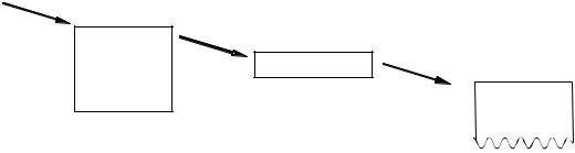
When the DPU-S445 (hereinafter it is referred to as “printer”) receives data (character codes and commands) from the host devices, it stores the data in the printer input buffer. The input buffer has a capacity of 4K bytes (4096 bytes). Then, the printer retrieves data from the input buffer. If data is character code, data is stored into the line buffer. If data is command, data is executed as command immediately.
The printer inputs character codes to the line buffer until the amount of character codes reaches the amount to be printed on one line, then prints the characters. The printer repeats this operation to print all the character data.
The relationship between the input buffer and line buffer is illustrated in Figure 1-1.
Host Device
Input Buffer
Line Buffer Print Operation
One Line of Characters is Printed.
Figure 1-1 Relationship between Input Buffer and Line Buffer
1-byte characters and 2-byte characters
The printer can print two-size characters; 1-byte characters and 2-byte characters. Table 1-1 lists the character types which can be printed by 1-byte and 2-byte characters.
Table 1-1 Character Types and Relationship between 1-byte and 2-byte Characters
|
Character Types |
|
|
1-byte characters |
Katakana character (ANK) |
Extended graphics character (IBM Compatible) |
|
|
Codepage 1252 |
2-byte characters |
Kanji, user-defined character |
|
|
*1 The size of a character to be printed differs depending on the font specified. (See 2.1 Printer Specifications.)
1-1
Line Spacing
Line spacing is the space between the lines of printed characters (See Figure 1-2).
ABC
Line Spacing
ABC
Figure 1-2 Line Spacing
This printer use a line thermal print mechanism, therefore, a paper feed step is necessary before printing characters or bit images.
The line feed command with printing feeds the paper for height of characters or bit images. Therefore, a paper feed amount which is smaller than character or bit image height is ignored. Printing with underline feeds the paper 4 dot lines in addition to the character height.
Line feeding without printing feeds the paper for specified line feed amount.
Character Spacing
Character spacing is the space between each character in the horizontal direction (See Figure 1-3).
A B
Character Spacing
Figure 1-3 Character Spacing
Line
The word “line” in this manual indicates a line of characters. For example, the sentence “the printer feeds paper one line” indicates that the printer feeds paper a line of characters.
Dot Line
The words “dot line” in this manual indicate a line of dots in the vertical direction. For example, the sentence “the printer feeds paper by one dot line” indicates that the printer feeds paper by the space of 1 dot.
Paper Auto-loading
The paper auto-loading function which can loads the cut paper from the paper slot automatically by using the paper feed motor.
Notation in the Technical Reference
Hexadecimal
Hexadecimal is showing as follows;
Example: 0AH (a hexadecimal unit 'H' is added behind a hexadecimal number.)
Character string
A character string is showing as follows;
Example: 'G' (a character string 'G' is enclosed with a single quotation mark.)
1-2
CHAPTER 2
SPECIFICATIONS
2.1 PRINTER SPECIFICATIONS
|
|
Table 2-1 General Specifications |
||
|
|
|
|
|
|
|
Item |
Specification |
|
|
|
|
||
Total number of dots |
832 dots/line |
|||
Effective dot number |
832 dots/line |
|||
Resolution |
|
W 8 dots/mm x H 8 dots/mm |
||
Printing width / paper width |
104 / 112 mm |
|||
Printing speed |
|
90 mm/s max. *1 |
||
|
|
|
24 dots 1-byte characters: 52 characters |
|
Number of character per line |
(right character space is 4 dots) |
|||
24 dots 2-byte characters: 26 characters |
||||
|
|
|
||
|
|
|
(left character space is 0 dot, right character space is 8 dots) |
|
Character size |
|
24 dots 1-byte characters: 24 x 12 dots |
||
|
16 dots 1-byte characters: 16 x 8 dots |
|||
(H x W) |
|
24 dots 2-byte characters: 24 x 24 dots |
||
|
|
|
16 dots 2-byte characters: 16 x 16 dots |
|
|
|
|
Katakana character set *2 |
|
Character set |
|
Extended graphics character set |
||
|
Codepage 1252 character set |
|||
|
|
|
||
|
|
|
JIS 1st and 2nd level of Kanji *2 |
|
|
|
|
Serial (RS-232C conformity) |
|
Interface |
|
USB (Ver.2.0 conformity) |
||
|
Infrared (IrDA Ver.1.2 / BHT-Ir protocol conformity) |
|||
|
|
|
||
|
|
|
Bluetooth (Ver.2.0+EDR conformity) *3 |
|
Input buffer size |
4K bytes |
|||
Dimensions (W x D x H) |
145 mm x 135mm x 8mm |
|||
Mass |
|
Approx. 490 g (including the battery pack, excluding paper) |
||
|
|
|
||
Operating temperature and humidity |
Temperature: 0 to 50°C |
|||
range |
|
Humidity: 30%RH to 80%RH (Non condensing) |
||
Storage temperature and humidity |
Temperature: -25 to 60°C |
|||
range |
|
Humidity: 5%RH to 90%RH (Non condensing) |
||
|
|
EMC |
VCCI Class B, FCC Class B, Industry Canada Class B, |
|
|
|
CE (EMC), CCC *4 , KC |
||
Regulations |
|
The wireless telegraph |
FCC, IC, CE (R&TTE), Radio Law of Japan, ANATEL |
|
|
law regulation |
|||
|
|
|||
|
|
conformity *3 |
|
|
|
|
Safety |
CB, CE (LVD), CCC *4 |
|
Countries under the regulations |
Japan, USA, Canada, EU, EFTA, Australia, New Zealand, |
|||
China, Korea, Taiwan, Brazil |
||||
|
|
|
||
2-1

*1: Using AC adapter, printing ratio is 7.5% or lower, thermal head temperature is 25°C. *2: SII Japanese font set installed (at shipping).
*3: Only for DPU-S445-01A-E. *4: Only for DPU-S445-00A-E.
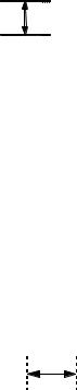
Dimensions
Paper Inlet
Paper Outlet
Unit : mm
Figure 2-1 Dimensions
2-2

2.2 SPECIFIED THERMAL PAPER SPECIFICATIONS
Table 2-2 Thermal Paper Provided by SII |
|
|
|
Item |
Specifications |
|
|
Model |
TP-341L-1 |
Type |
Normal paper roll |
|
|
Paper width |
112 0-1.0 mm |
Outside diameter |
48mm max. |
Paper thickness |
59 ±5 μm |
|
|
Printing surface of Paper roll |
Outside |
|
|
Table 2-3 Specified Thermal Paper Specifications
Item |
|
Specifications |
||
|
|
|
|
|
|
|
PD160R-N |
|
Oji Paper Co., Ltd. |
|
Paper roll |
TF50KS-E2D |
|
Nippon Paper Industries Co. |
|
|
|
|
|
P350 |
|
Kanzaki Specialty Papers |
||
|
|
|
||
Paper mode *1 |
|
|
|
|
|
KT55F20 |
|
Papierfabrik August Koehler AG |
|
|
Cut paper |
TC98KS-LH |
|
Nippon Paper Industries Co. |
|
|
|
|
|
|
TF8067 |
|
Mitsubishi Hi-Tech Paper |
|
|
|
|
||
|
|
|
|
|
|
Label paper |
TL69KS-HW76B |
|
Nippon Paper Industries Co. |
Paper width |
112 0-1.0 mm |
|
|
|
Outside diameter |
50 mm max. |
|
|
|
|
|
|
||
Inside diameter |
8 mm min. (Label paper: Outside diameter of paper core should be |
|||
25.4 mm min.) |
|
|
||
|
|
|
|
|
Spectral reflectivity |
Black, near-infrared reflectance should be 6% and below. |
|||
|
|
|
|
|
Printing surface of Paper roll |
Outside |
|
|
|
*1 Use each specified thermal paper in an applicable thermal paper mode.
2-3
2.2.1 Timing Mark for the Cut Paper Dimensions
112 0-1.0
9 min.
16  5
5
3 max.
Insertion direction of paper
Unit : mm
Figure 2-2 Timing Mark for the Cut Paper (back surface)
2-4

(1)Example of use of the cut paper
An example of use of the cut paper is shown Figure 2-2.
(a)Set the function setting of Paper Mode to “Cut paper”.
(b)Set the paper length as page length.
(c)Insert the cut paper.
(d)Print data within the printable area shown in Figure 2-3. (The position of print end must be at the position of 15mm or longer from the bottom edge of the paper.)
(e)The cut paper is ejected by sending Form Feed command at the end of printing. Repeat steps (c) to (e).
Paper length (90 to297mm)
A B C D E F 0 1 2 3 4 5 a b c d e f
Form Feed command
Printable area
6mm
Page length Paper length
 15mm or longer
Paper ejection
Figure 2-3 Example for the Cut Paper
2-5

2.2.2 Thermal Label Paper Dimensions
6
8
250 to 20
3
b. Paper cut position
Printing area
112 0-1.0
110
A B C D E F 0 1 2 3 4 5 a b c d e f
Form Feed command
To the beginning of the next label
A B C D E F 0 1 2 3 4 5 a b c d e f
Thermal label paper (surface)
Page length Label length
Non-printing area
 a. Print start position
12 |
|
|
|
|
|
|
|
|
|
5 |
|||||
|
|
|
|
|
|||
|
|
|
|
|
|
|
|
|
|
|
9 min. |
||||
3 max. |
|||||||
|
|
|
|
|
|
|
|
Backing (back surface)
Unit : mm
Figure 2-4 Example for Thermal Label Paper Dimensions
2-6

(1)Example of use of thermal label paper
An example of use of the thermal label paper is shown Figure 2-4.
(a)Set the function setting of Paper Mode to “Mark Roll Paper”.
(b)Insert the thermal label paper.
(c)Set the page length as the length from the beginning of the current label to the beginning of the next label.
(d)Set the skip amount (non-printing area) between labels.
(e)Print data within the printable area.
(f)Use Form Feed command to find the beginning of the next label. The mark on the next label is detected and the beginning of the next label is located by sending Form Feed command.
The print start position after the beginning of the next label is placed at position 'a', and the paper cut position is 'b' as shown in Figure 2-4.
Repeat steps (e) to (f).
(NOTE) When Mark Position Correct of SWDIP 4-5 is set as Enable, the printer operates paper feeding to backward 5 mm just before printing process after placing print start position.
If this function set as Enable, use the thermal label paper 40mm or longer length to prevent paper jamming from feeding paper backward.
2-7

2.3 SPECIFIED BATTERY PACK SPECIFICATIONS
Item |
Specification |
|
|
Model |
BP-L0725-A1 |
|
|
Available printing lines *1 |
10000 lines min. |
Battery Cycle Life *2 |
300 cycles |
*1: 25 C, character spacing is 4 dots, line spacing is 34 dots, TF50KS-E2D selection, print density is 100%, continuous printing with 'H' 1-byte characters, serial communication, fully charged with 8.4 V by specified battery charger.
*2: 25 C, charged in the printer with specified AC adapter, print ratio is 12.5%, charged with 70%* or more of fully charged. * The rate in environment of 0 to 50 C becomes 40% or more.
2-8
2.4PRECAUTIONS FOR USE
Always print the two-dimensional bar code and ladder bar code (its bar is to be printed verticality to the printer) within 0 to 40°C to ensure the bar code's reading accuracy.
The two-dimensional bar code and ladder bar code printing always requires the low speed mode to ensure its reading accuracy. Set the print speed to the low speed mode by using Motor Speed Select (GS 'E') command.
The height of the ladder bar code requires over 10 mm to ensure its reading accuracy.
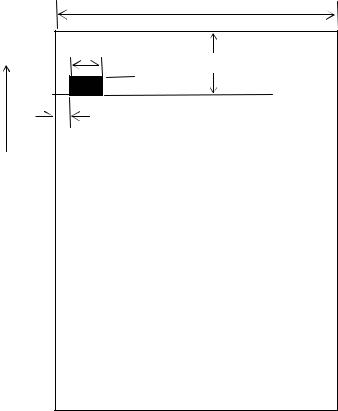
To print data at a temperature of 15°C or lower, be sure to set data for black printing to 78 mm or less (see figure below).
At a low temperature, the total number of black printing areas (w1 + w2 in the figure above, for example) should not exceed 78mm for parts having high printed ratios* (including the ladder bar code part).
Be aware, in particular, that reverse printing and ruled line tend to increase the ratio.
*Parts where many black dots are used when viewed in the direction vertical to the paper feed direction.
Use of the battery pack at low temperature will run out of power in a shorter time.
When printing ruled lines, a 2-dot configuration is needed. In case of a 1-dot configuration, the printed lines may be invisible.
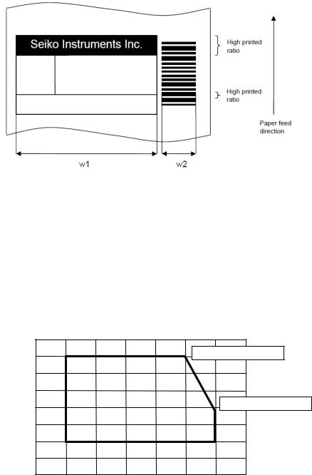
Always use the printer within the shadowed range depicted in figure below Relationship between Temperature and Humidity.
[% RH] |
|
|
|
|
|
|
|
|
|
90 |
|
|
|
|
|
|
|
|
80 |
|
|
|
|
|
40°C, 80%RH |
|
Humidity |
70 |
|
|
|
|
|
|
|
60 |
|
|
|
|
|
|
|
|
50 |
|
|
|
|
|
|
50°C, 47%RH |
|
40 |
|
|
|
|
|
|
|
|
|
|
|
|
|
|
|
|
|
|
30 |
|
|
|
|
|
|
|
|
20 |
|
|
|
|
|
|
|
|
10 |
0 |
10 |
20 |
30 |
40 |
50 |
[°C] |
|
|
|||||||
|
|
|
|
Temperature |
|
|
|
|
|
|
|
|
|
2-9 |
|
|
|

When using a Bluetooth interface, the radio environment around the printer may cause a failure in communications. This is due to the specifications of Bluetooth, which is a radio communications standard.
When handling this product, be aware of static electricity. If the static electricity is discharged, this could case communication failure. When this problem occurs, disconnect the USB connector that is connected to the host device and wait few seconds before connect it again.
When the printer is left unused for a long period of time, a white powder appears to the surface of platen. (This is the powder by which an ingredient of a thermal paper was recrystallized.)
If the powder appears to the platen, wipe the platen with ethanol and use the printer after ethanol has dried completely.
Also, make sure not to adhere ethanol except the platen area. If ethanol adheres except the platen area, wipe it off immediately.
(NOTE) Refer to "SAFETY PRECAUTIONS" and "OPERATING PRECAUTIONS" on DPUS445 SERIES USER'S GUIDE which be included with the printer for other precautions.
2-10
CHAPTER 3
INTERFACE
This chapter describes 4 types of the interface specifications which are required to connect the host device with the printer.
Irrespective of the interface used, amount of the input buffer in the printer is 4k bytes, and transmission buffer is 768 bytes. If the transmission buffer becomes the condition of the buffer full, the printer waits data processing until the buffer can be received data. Be aware that printing process does not performed in that meantime.
3.1 SERIAL INTERFACE SPECIFICATIONS (RS-232C CONFORMITY)
(1) General specifications
Item |
Specification |
|
|
|
|
Synchronization |
Asynchronous |
|
|
|
|
Signal level |
MARK = –3.0 to –15.0 V: Logic '1' |
|
SPACE= +3.0 to +15.0 V: Logic '0' |
||
|
||
Baud rate |
1200, 2400, 4800, 9600, 19200, 38400, 57600, 115200 bps |
|
|
|
|
Data bit length*1 |
7 bits or 8 bits |
|
Stop bit length |
1 bit or 2 bits |
|
|
|
|
Parity |
None, odd or even |
|
|
|
|
Reset |
Break signal input to RxD (20ms or longer) |
*1: When selecting 7 bits, the data transmission such as the status from a printer is not performed. Also, the command that uses 80H and more parameters and character printing over 80H
are not available.
(2) Pin assignment
Pin No. |
Name |
I/O |
Function |
|
|
|
|
|
|
1 |
N.C. |
- |
No connection |
|
|
|
|
|
|
2 |
TxD |
O |
Sends data from the printer to the host device. |
|
|
|
|
|
|
3 |
RxD |
I |
Receives data from the host device. |
|
Break signal input (SPACE) resets the printer. |
||||
|
|
|
||
4 |
- |
- |
Internally connected with pin No.6. |
|
|
|
|
|
|
5 |
GND |
- |
Signal ground |
|
|
|
|
|
|
6 |
- |
- |
Internally connected with pin No.4. |
|
|
|
|
|
|
7 |
CTS |
I |
Outputs SPACE when the host device can receive data. |
|
|
|
|
|
|
8 |
RTS |
O |
Outputs SPACE when the printer can receive data. |
3-1

(3) Connector
8 1
3260-8S3: HIROSE ELECTRIC CO., LTD. or equivalent
(4) Examples of connection with the host device (a standard personal computer)
Printer |
|
|
Host device |
Printer |
|
|
Host device |
N.C. |
1 |
1 |
F.G |
N.C. |
1 |
|
|
TXD |
2 |
2 |
TXD |
TXD |
2 |
2 |
RXD |
RXD |
3 |
3 |
RXD |
RXD |
3 |
3 |
TXD |
DSR |
4 |
4 |
RTS |
DSR |
4 |
4 |
DTR |
GND |
5 |
5 |
CTS |
GND |
5 |
5 |
S.G |
DTR |
6 |
6 |
DSR |
DTR |
6 |
6 |
DSR |
CTS |
7 |
7 |
S.G |
CTS |
7 |
7 |
RTS |
RTS |
8 |
20 DTR |
RTS |
8 |
8 |
CTS |
|
SHELL |
(Shield) |
SHELL |
SHELL |
|
(Shield) |
SHELL |
|
|
|
|
|
||||
8-pin – 25-pin |
|
|
8-pin – 9-pin |
|
|||
(5)Data reception
Busy control
In Busy Control, RTS outputs MARK until the printer is ready to receive data after power ON. After the printer is ready, RTS outputs SPACE and the received data is input to the input buffer. When there are 33 bytes or less remaining in the input buffer, RTS outputs MARK. The host device does not transmit data during RTS outputs MARK. When the input buffer is ready to receive data (there are 65 bytes or more in the input buffer) after stopping data reception, RTS once again outputs SPACE. If an error occurs in the printer, RTS outputs MARK and inhibits data entry until the error is cleared. If an error is cleared, RTS outputs SPACE again.
For RTS output when an error occurs, the setting is changed by Busy Output When Error Occurs at function setting.
Xon/Xoff control
In Xon/Xoff control, TXD outputs Xon code (11H) from power ON until the printer is ready to receive data. Received data is input to the input buffer. When there are 65 bytes or less remaining in the input buffer, TXD outputs Xoff code (13H). The host device does not transmit data while Xoff code is received. When the input buffer is ready to receive data (there are 129 bytes or more in the input buffer) after stopping data reception, TXD once again outputs Xon code. When this
control method is selected, the RTS signal always outputs SPACE. If an error occurs in the printer, TXD outputs Xoff code and inhibits data entry until the error is cleared. When the error is cleared, TXD outputs Xon code again.
For Xoff code transmission when an error occurs, the setting is changed by Busy Output When Error Occurs at function setting.
Data reception error in serial communication
When Parity is selected as Yes by the function setting, a '!' is printed next to data in which a parity error occurred and a '?' is printed next to data in which any other error (framing error, etc.) occurred. If a serial data reception error occurs, no error indication other than the printing of '!' and '?' is performed (for example, the ERROR lamp does not light).
3-2

(6)Data transmission
Busy control
In Busy Control, the conditions which transmit status information to the host device from the printer are as follows;
When CTS Control of function setting sets to Enable, the printer sends data from TXD after confirming CTS status as SPACE.
When CTS Control of function setting sets to Disable, the printer sends data from TXD regardless of the condition of the host device.
Xon/Xoff control
In Xon/Xoff control, the conditions which transmit status information to the host device from the printer is that the printer sends data from TXD regardless of the condition of the host device.
(NOTE) Be aware that if the transmission buffer becomes full, the printer does not print until the buffer is available.
3-3
3.2 USB INTERFACE SPECIFICATIONS
(1) |
General specifications |
|
|
|
|
||||
|
|
|
|
|
|
|
|
|
|
|
|
|
|
Item |
|
|
Specification |
|
|
|
|
|
|
|
|
|
|
|
|
|
|
|
USB Version |
|
|
Ver 2.0 conformity |
|
||
|
|
|
|
|
|
|
|
|
|
|
|
|
USB Printing class specification |
|
1.1 |
|
|||
|
|
|
Communication speed |
|
|
Full speed 12 Mbps |
|
||
|
|
|
|
|
|
|
|
|
|
|
|
|
Communication protocol |
|
|
Bulk transfer |
|
||
(2) |
Pin assignment |
|
|
|
|
|
|
||
|
|
|
|
|
|
|
|
|
|
|
|
|
Pin No. |
Name |
|
I/O |
|
Function |
|
|
|
|
|
|
|
|
|
||
|
|
1 |
Vbus |
|
- |
USB power supply |
|
||
|
|
2 |
D- |
|
I/O |
USB data signal |
|
||
|
|
|
|
|
|
|
|
||
|
|
3 |
D+ |
|
I/O |
USB data signal |
|
||
|
|
|
|
|
|
|
|
||
|
|
4 |
N.C. |
|
- |
No connection |
|
||
|
|
5 |
GND |
|
- |
GND |
|
||
|
|
|
|
|
|
|
|
|
|
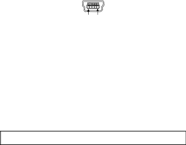
(3) |
Connector |
|
|
|
|
|
|
||
1 5
Mini B type
(4)Data reception
USB data reception uses a bulk-out transfer method.
The data are received even during the printing operation, and when the data accumulate in the input buffer by the amount of input buffer + 2 packets, the NAK response continues until amount of the input buffer becomes 129 bytes or more.
The number of bytes that can be received with one packet is maximum 64 bytes. When an error occurs, the NAK response continues until the error is cleared after receiving data of 2 packets.
For the operation when an error occurs, the setting is changed by Busy Output When Error Occurs at function setting.
(5)Data transmission
USB data transmission uses a bulk-in transfer method.
The response data are stored temporarily in the transmission buffer, and a response is made to the bulk-in packet request from the host device. If no transmission data exist, the zero length data is returned when the bulk-in request is received. The number of bytes that can be transmitted with one packet is maximum 64 bytes.
(NOTE) Be aware that if the transmission buffer becomes full, the printer does not print until the buffer is available.
3-4
3.3 INFRARED INTERFACE SPECIFICATIONS
The printer can communicate with the host device through the infrared interface.
The infrared interface used in the printer conforms to the physical layer standard (Ver 1.2) specified by the Infrared Data Association (IrDA).
The printer supports the minimum infrared transmission functions as the second station specified by IrDA and BHT-Ir protocol specified by DENSO CORPORATION.
3.3.1 Physical Specifications
Item |
Specification |
|
|
Transmission distance |
0.2m max. |
Transmission range |
15° |
|
|
Infrared transmission pulse width |
Typ. 1.63 s |
3.3.2 IrDA Specifications
The printer conforms to IrDA Ver.1.2 and supports only the minimum infrared transmission functions as the second station.
(1) Transmission specifications
Item |
Specification |
|
|
Baud Rate |
9600 to 115200 bps |
|
|
Data Size |
64 to 512 bytes |
Window Size |
1 |
|
|
Additional BOFs |
0 to 48 |
Maximum Turn Around Time |
500ms |
|
|
Minimum Turn Around Time |
10ms |
|
|
Link Disconnect/Threshold Time |
3 to 40 s |
(2)Services supported by IrLAP
1.Connect service
2.Data service
3.Disconnect service
IrLAP does not support a transfer for non-number and sniffing services.
The printer does not initiate connections.
Service Hint |
Printer, IrCOMM |
Device Nickname |
DPU-S445 |
|
|
3-5

(3)Services supported by IrLMP
1.Connect service
2.Disconnect service
3.Data service
A single LSAP address does not support multiple connections. furthermore, LSAP address 7 and 9 can not share the connection state. If multiple connections are requested, a disconnect request is transmitted and the printer waits until it receives a disconnect command.
IAS server: LSAP address 0 IAS client: Not supported
Printer application: LSAP address 7 (3-wireraw/IrLPT) and address 9 (3-wire/9-wire)
(4)IAS service
IAS service is supported by 'GetValueByClass' only.
Return values for GetValueByClass inquiries are listed below.
1.
Inquiry
Class |
Device |
|
|
Attribute |
Device Name |
Return value |
|
|
|
Device Name |
Sll Thermal Printer |
|
|
2. |
|
Inquiry |
|
|
|
Class |
IrDA:IrCOMM |
|
|
Attribute |
Parameters |
|
|
Return value |
|
|
|
Service type |
3-Wireraw |
Port type |
Serial |
|
|
4.
Inquiry |
|
|
|
Class |
IrLPT |
|
|
Attribute |
IrDA:IrLMP:LsapSel |
Return value |
|
|
|
Lsap address |
7 |
|
|
5. |
|
|
|
Class |
IrDA:IrLMP |
|
|
Attribute |
IrDA:IrLMP:LsapSel |
|
|
Return value |
|
|
|
Lsap address |
7 |
3
Inquiry
Class |
IrDA:IrCOMM |
|
|
Attribute |
IrDA:IrLMP:LsapSel |
|
|
Return value |
|
|
|
Lsap address |
7 |
|
|
6.
Inquiry
Class |
|
IrDA:IrCOMM |
|
|
|
Attribute |
|
IrDA:TinyTP:LsapSel |
|
|
|
Return value |
|
|
|
|
|
Lsap address |
9 |
|
|
|
|
(5)TinyTP
Flow control is performed by this layer when connecting with 3-Wire or 9-Wire.
'5' is transferred to the primary station as the initial credit when connecting the LMP layer.
3-6

(6)IrCOMM
Supports 3-Wireraw, IrLPT, 3-Wire and 9-Wire.
Flow control is performed only by the IrLAP layer when connecting with 3-Wireraw or LrLPT.
Flow control is performed by the TinyTP layer when connecting with 3-Wire or 9-Wire. Xon/off control and line status control are not supported.
(7)Command response processing during IrDA transmission
If the printer receives a command that requires transmission of data from the remote station during IrDA transmission, and then stores the data in the transmission buffer and transfers them at transmit timing to the remote station.
The printer clears a response data in the transmission buffer when transmission to the remote station is disconnected for busy state. When the remote station is in disconnection, the printer does not store the data in the transmission buffer and the data is cleared.
However the printer transfers the status regardless of the remote station state when initial automatic status transmission is enabled.
The printer transfers status when the remote station is connected again if automatic status transmission has not deactivated by power off.
(NOTE) Be aware that if the transmission buffer becomes full, the printer does not print until the buffer is available.
3-7
3.3.3 BHT-Ir Specifications
The printer also supports BHT-Ir communication specified by DENSO CORPORATION.
The printer can receive data from the 'BHT-6500' made by DENSO CORPORATION when Data Input Mode SWDIP2-1 and SWDIP2-2 is selected to BHT-Ir.
The inherent processing of the printer for BHT-Ir communication is shown below: See BHT-Ir protocol specification for details of the protocol.
(1)ID
Printer ID: 3445H (fixed)
(2)Text format
Only text is valid.
Files with 'PD3', 'FN3' or 'EX3' extension can not be processed.
(3)Input buffer full processing when receiving header.
Upon receiving the header, the printer inhibits connection with the host device when the remaining amount of the input buffer becomes 512 bytes or less after subtracting the field number of the data text indicated in heading text.
(4)Input buffer full processing when receiving data
Upon receiving data, the printer sends WACK supervisory sequence to a host device for requiring temporarily delay of the data output from the host device as the input buffer full state when the remaining amount of the input buffer is 255 bytes or less.
Then, the printer sends the ACK supervisory sequence to the host device to restart data transmission when the remaining amount of the input buffer is 512 bytes or more.
The printer transfers the EOT supervisory sequence and stops when the input buffer full status continues more than 1 minute.
(5)Command response processing during BHT-Ir transmission
No response command is transferred in BHT-Ir transmission mode. Although response data is generated, it is discarded.
3-8

3.4 BLUETOOTH INTERFACE SPECIFICATIONS
Bluetooth-supporting model can perform wireless communication by Bluetooth communication function. When Data Input Mode of the function setting is set to Bluetooth/USB, internal Bluetooth module of the printer operates regardless of its communication.
When using the printer at the place with radio limitations like a hospital or an airplane, set Data Input Mode of the function setting as Serial/USB or IrDA/USB to stop Bluetooth communication.
(1) General specifications
Item |
Specification |
|
|
Bluetooth version |
2.0+EDR conformity |
Transmitted electric power class |
Class 2 |
|
|
Connection mode |
Peer-to-peer |
Profile |
SPP |
|
|
PIN code*1 |
None (default) |
Device name*1 |
DPU-S445 (default) |
*1: This specification can be changed by the command.
(2)Security
The printer does not set with PIN code or the Link Key in default. Bluetooth device uses security mode 1, so no encryption is used.
Bluetooth device becomes security mode 3 if PIN code is set by Set default/Set test print header command or Bluetooth Link Key selection of the function setting is set to Enable, and encryption is used. When the setting of Bluetooth Link Key is Disable and selection of PIN code is canceled, Bluetooth device becomes security mode 1 again, and no encryption is used.
(3)Input buffer
Capacity of input buffer for internal Bluetooth module is 3Kbytes. Received data is stored in the input buffer of Bluetooth module, and then these data is to be processed after data transfer to input buffer of the printer.
If an error occurs, the printer stops receiving data after data that stored into input buffer of Bluetooth until the error is cleared.
For the operation when an error occurs, the setting is changed by Busy Output When Error Occurs at function setting.
(NOTE) Be aware that if the transmission buffer becomes full, the printer does not print until the buffer is available.
(4)Link key saving
If the Bluetooth Link Key selection of the function setting is set to Enable, the printer saves the link key to connect with the host device in the pairing process.
The host devices can be saved up to 10. When requiring to save the 11th host device, perform the pairing after clearing the saved host devices in the printer.
To clear the all of saved host device data, set the Bluetooth Link Key selection of the function setting as Disable after setting Data Input Mode of the function setting as Bluetooth. The printer clears the stored host device data after the above process.
3-9
CHAPTER 4
FUNCTION SETTINGS
4.1 FUNCTION SETTING
The communication method, a paper types, and so on can be preset in this printer. Preset these functions before using the printer.
The function settings of the printer are stored in FLASH memory. Once these are set, these are stored until changing again.
The function settings are specified through the software DIP switch (hereinafter referred to as SWDIP switch), SWDIP1 to 4.
Details for settings of SWDIP 1 to 4 are described below. The value that is indicated by boldface and shaded cell shows a default setting value. The words in parentheses in the table are indicated in test print.
4-1
 Loading...