

Page 1
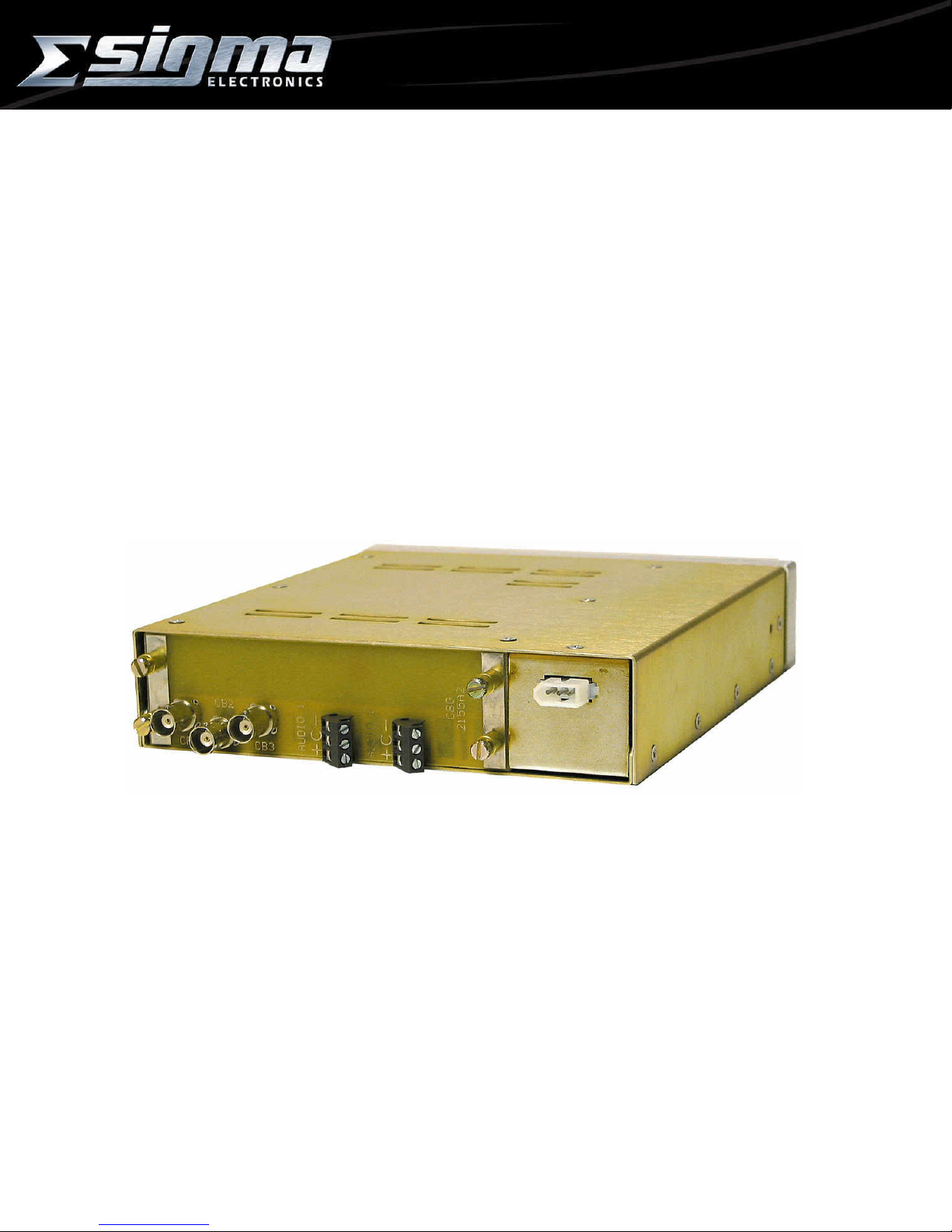
CBG-2655A
COLOR BAR, TONE, & ID GENERATOR
SERVICE MANUAL
SIGMA ELECTRONICS, INC.
P.O. Box 448
1027 COMMERCIAL AVENUE
EAST PETERSBURG, PA 17520-0448
(717) 569-2681
Page 2
+ C
-
GENERAL:
The CBG-2655A provides three (3) identical outputs of EIA Split-field Color Bars with Reverse Bars,
Pluge Signal, and 100% White Signal for system and monitor setup. A stereo audio tone generator is
also provided by the CBG-2655A. The module is compatible with either balanced or unbalanced audio
signal configuration. A twelve (12) character ID is available. The character generator must be
programmed by Sigma Electronics at the time of the order. If the character generator ID needs to be
changed or added after the module is delivered, Sigma Electronics will perform this task for a small
setup charge upon the return of the module.
The CBG-2655A consists of a CBG-2155A module and the Sigma Stand-Alone Box, SSB-21. For
proper operation this module should not be mounted into any other 2100 Series frame. Installation of
this module into any other power supply/frame manufactured by Sigma or any other manufacturer may
void the warranty.
POWER:
The CBG-2655A operates from bus voltages of unregulated +20Vdc and -20Vdc. These voltages are
supplied by the Sigma Stand-Alone Box SSB-21 power supply. The module regulates the bus voltage to
+5Vdc and -5Vdc. Circuit protection is provided by PTC thermistors (Positive Temperature Coefficient
Thermal Resistor) which serve as a permanent self-resetting fuse. In the event of excessive current draw
on either of the two bus lines the PTC thermistor on that line will open. Upon correction of the fault, the
PTC thermistor will cool to an operational temperature and reset.
FRAME:
The CBG-2655A module must reside in the Sigma Stand-Alone Box, SSB-21. This is a desk top
box. Rack mounting is achieved with the optional RMK-26 rack mount kit. This will hold up to three
stand-alone Boxes in 1 RU (1.75”) without the need for blank panels when mounting only one or two
boxes.
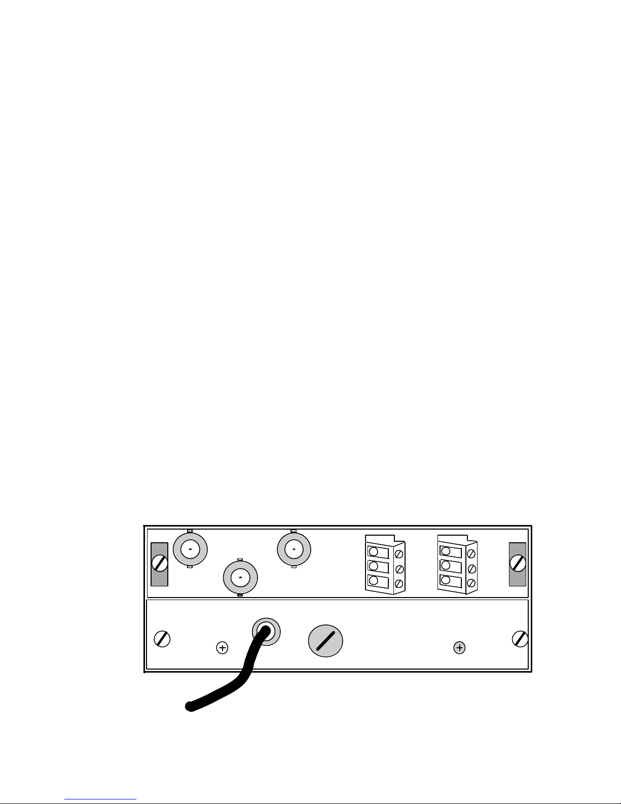
CONNECTIONS:
Wiring to the module is performed via the connectors located on the rear panel. BNC connectors are
used for the video outputs. Three-pin screw terminal connectors are provided for the audio. (Figure 1)
OUTPUT: There are three (3) video outputs on the rear panel of the unit. Each output is designed to
drive a 75? load. The outputs are common in signal content. The audio screw terminals provide both
continuous (channel 1) and 50% duty cycle (channel 2) tones for stereo system checks.
REAR PANEL CONNECTIONS
Figure 1
CB1
CB2
115
VAC
CB3
AUDIO 1
¼ AMP
AUDIO 2
+ C -
CBG-2655A
Page 1 of 3 CBG-2655A
Page 3

AUDIO CONFIGURATIONS:
The audio outputs provide a 1 kHz Tone. The connector labeled AUDIO 1 provides a continuous 1
kHz tone. The connector labeled AUDIO 2 provides a 1 kHz tone at a 50% duty cycle operating at one
(1) cycle per second. Equipment receiving the audio signal must be evaluated to determine if it is
balanced or unbalanced. After this determination has been made, refer to the drawings provided in
Figure 2 to select the proper audio configuration. Audio output impedance is 600? , ideally suited for a
balanced configuration. The output level is factory set for a balanced configuration, this assumes both
outputs are terminated into a 600? load.
Balanced Out Unbalanced Out
Audio 1 or 2 Output Audio 1 or 2 Output
FIGURE 2
CBG-2155A
+
C
-
Audio Out
+
C
-
6
0
0
?
CBG-2155A
+
C
-
Audio Out
+
C
Open
ADJUSTMENTS:
YC balance, DC offset, Video gain, and Audio level are all set for optimum performance by Sigma
Electronics. If necessary, these parameters may be readjusted via the controls listed below.
R20: ..........YC Balance. Luminance signal to Chroma signal balance.
R24: ..........DC Offset adjustment.
R28: ..........Video Gain. Factory adjusted for 1 Vp-p-P output
R59: ..........Audio level. Optimized by factory setup for balanced configuration.
SPECIFICATIONS:
VIDEO:
OUTPUT: ................................ (3) EIA Split-field Color Bars with Reverse Bars, Pluge
Signal and 100% White Signal
VECTOR ACCURACY: ........... Within ?2.5? and ?2.5 IRE, (Small Boxes on
vectorscope graticule).
TIMING: .................................. per RS -170A
RESIDUAL SUBCARRIER: ..... < 1 IRE p-p
OVERSHOOT: ........................ < 2 IRE
TILT: ....................................... < 1 IRE line or field
CONNECTORS: ..................... 3, BNC
AUDIO:
OUTPUTS: ............................. 1 stereo tone, balanced
FREQUENCY: ........................ 1 kHz ?10%, 1 channel continuous,
1 channel pulsed 50% duty cycle, 1 sec. pulse rate
LEVEL: ................................... 0 dBm (600? ), ? 0.5dB
IMPEDANCE: ......................... 600?
CONNECTORS: ..................... 2 each, three-pin screw terminal
Page 2 of 3 CBG-2655A
Page 4

SPECIFICATIONS (cont.)
POWER:
Power Consumption:
ENVIRONMENTAL
Operational Temperature Range:
MECHANICAL
Size:
Weight:
TECHNICAL MANUAL:
A manual including schematics, circuit description, parts list and setup guide is available upon
request. This information is intended for the service of the module. Modules should be serviced by
qualified personnel only. Sigma Electronics, Inc. recommends service to be performed by our Factory
Service Center.
NOTES:
All specifications, drawings, dimensions, weights and other details are subject to change without notification.
Information is intended to give a general overview of product performance and operations.
Sigma Electronics, Inc.; P.O. Box 448; 1027 Commercial Avenue; East Petersburg, PA 17520-0448
Main Office: Tel: (717) 569-2681 Fax: (717) 569-4056
REV2 NOV99 CBG-2655A
Page 3 of 3 CBG-2655A
 Loading...