

Page 1

SIGMA SYSTEMS
MODELS C4 & CC-3
.5
PROGRAMMABLE TEMPERATURE CONTROLLER / INTERFACE
OPERATING & PROGRAMMING MANUAL
Firmware Version 7.5.2
Manual Revision 4
June 3, 1999
SIGMA SYSTEMS CORPORATION
1817 John Towers
San Diego, California 92116 USA
TEL: (619) 258-3700 WWW.SigmaSystems.Com FAX: (619/258-3712)
C4 Manual Rev 7.5.2
Page 2

Copyright 1997, 1998
Sigma Systems Corporation
1817 John Towers
El Cajon, California 92020 USA
All rights reserved
The manual may be reproduced, in whole, or in part, solely for the purposes of use
and training for the use, of Sigma Systems equipment, or as required to assist in the
sale of new Sigma Systems equipment. No modification of the content is permitted.
C4 Manual Rev 7.5.2
Page 3

TABLE OF CONTENTS
1. INTRODUCTION ................................................. 9
1.1 Models C4 & CC-3.5 Explained ................................. 9
1.2 General Description ........................................ 10
1.3 Custom Features / Interchangeability WARNING .................. 11
1.4 Release 7.5.2 Firmware ..................................... 11
1.5 C4 vs. CC-3 Differences (What’s New) ......................... 12
1.5.1 Hardware & Stability Improvements ..................... 12
1.5.2 Hardware Change (EEPROM replaces BBSRAM) .......... 12
1.5.3 Firmware Uploads ................................... 13
1.5.4 Forced Start from PROM Firmware ..................... 13
1.5.5 Front Panel Information Display at Startup ................ 13
1.5.6 Temperature Out of Range Shutdown ................... 13
1.5.7 Internal Error Shutdown Conditions ..................... 14
1.5.8 Fahrenheit Temperature Scale Supported ................ 14
1.5.9 Temperature Probe Correction (Calibration) ............... 14
1.5.10 “Bumpless” Temperature Control ...................... 14
1.5.11 Intelligent 2 Probe Control (Probe Averaging) ............ 15
1.5.12 Default Setup Parameters Restore..................... 16
1.5.13 Program Mode Step Insert & Delete .................... 16
1.5.14 Program Mode Any Step Points to Step 100 ............. 16
1.5.15 Program Mode Safer Program Clear ................... 16
1.5.16 Program Mode Run Time Program Pre-check ............ 16
1.5.17 Remote Mode EIA-232 Baud Rate Improvement .......... 16
1.5.18 Remote Mode EIA-232 Port Initialization ................ 17
1.5.19 Remote Mode Fault Tolerant Parser .............. 17
1.5.20 Remote Mode System Information Queries .............. 17
1.5.21 Remote Mode Operation Information Queries ............ 17
1.5.22 Remote Mode Setup Parameter Commands ............. 18
1.5.23 Remote Mode IEEE-488 (GPIB) Monitoring .............. 18
1.5.24 Setup Mode Easier Parameter Access .................. 18
2. PHYSICAL DESCRIPTION......................................... 19
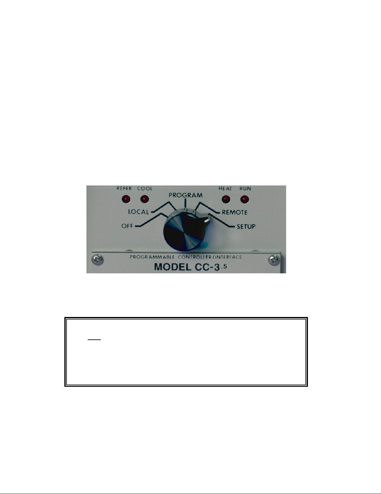
2.1 Front Panel ............................................... 19
2.1.1 Digital LED Display.................................. 19
2.1.2 LED Indicators ..................................... 19
2.1.3 Mode Switch ....................................... 20
2.1.4 Keyboard ......................................... 21
2.2 Rear Panel Connections .................................... 22
3. GENERAL OPERATION & ERROR CONDITIONS ...................... 23
3.1 Startup Displays ........................................... 23
3.1.1 Model Number and Firmware Version Number Display ...... 23
3.1.2 Temperature Range Display ........................... 23
3.1.3 Serial Number Display................................ 24
C4 Manual Rev 7.5.2
3
Page 4

3.2 Updating Firmware .........................................24
3.2.1 Upgrading Firmware by PROM Replacement ..............25
3.2.2 Upgrading Firmware by Uploading through C4 Serial Port ....25
Making the physical connection for upload ................26
Running the upload software on the PC ..................26
Starting the upload on the C4 .......................... 27
3.3 Restoring Setup Parameters to Default Values....................27
3.4 Fahrenheit Operation .......................................28
3.5 System Operating (Temperature) Range ........................29
3.6 Probe Out of Range Shutdown ................................29
3.6.1 Effect of Probe Correction on Out of Range Shutdown .......30
3.6.2 Probe Out of Range Shutdown Reported in Error/Status String
.................................................30
3.6.3 Clearing a Probe Out of Range Shutdown ................30
3.7 Internal Error Shutdown Conditions ............................31
3.7.1 Watchdog Timer ....................................31
3.7.2 Memory signature checking ...........................31
3.7.3 Setup parameter integrity checking......................32
3.8 Software Probe Correction (Calibration) .........................32
3.9 Status and Error Reporting ...................................33
3.10 Fail-safe System .......................................... 34
4. INTELLIGENT 2 PROBE CONTROL..................................35
4.1 How Intelligent 2 Probe Control functions ........................36
4.2 Preparing for Intelligent 2 Probe Control ........................37
4.3 Using Intelligent 2 Probe Control ..............................38
5. LOCAL MODE ( Basic Operation ) ...................................39
5.1 Displaying Temperature .....................................39
5.2 Displaying and Changing the Setpoint ..........................40
5.3 Controlling to a Setpoint .....................................41
5.4 Compressor Control ........................................ 42
6. PROGRAM MODE ...............................................43
6.1 Description of a Program Step ................................43
6.1.1 Format of a Program Step.............................44
6.1.2 Maximizing Ramp Speed & Other Ramp Considerations .....45
6.2 Clearing Program Memory (Reinitializing program steps)............46
6.3 Displaying Program Steps.................................... 46
6.4 Entering or Changing a Program Step ..........................47
6.5 Insert Program Step ........................................ 47
6.6 Delete Program step........................................48
6.7 Running (Executing) a Program ...............................48
6.7.1 Program Run Time Information/Considerations ............49
6.7.2 Run Time Pre-read Errors .............................49
No Probe 2 Error ...................................50
4
C4 Manual Rev 7.5.2
Page 5

Invalid Loop Count Error ............................. 50
Setpoint Out of Range Error .......................... 50
6.8 Special Commands ........................................ 50
6.8.1 Controlled Program Looping ........................... 51
6.8.2 External Compressor On ............................. 52
6.8.3 External Compressor Off ............................. 52
6.8.4 Optional Aux/Power Control Port On .................... 52
6.8.5 Optional Aux/Power Control Port Off .................... 52
6.9 Common Programming Issues................................ 53
6.9.1 Step Numbering .................................... 53
6.9.2 Changing Substep Values ............................ 53
6.9.3 Control Ports....................................... 53
7. REMOTE MODE................................................. 55
7.1 EIA-232 Interface .......................................... 55
7.2 IEEE-488 Interface ......................................... 55
7.3 Command Summary (by functional group) ....................... 56
7.4 System Information Queries.................................. 57
7.4.1 QV Query Firmware Version........................... 57
7.4.2 QN Query Controller Serial Number ..................... 57
7.4.3 QR Query Controller Temperature Range ................ 58
7.4.4 QS Query Setpoint & Control Probe Number .............. 58
7.4.5 QF, QFA Query Setup Parameter Value ................ 59
7.5 Operation Information Queries & Commands .................... 61
7.5.1 RS, RSA Request Status Byte ......................... 61
7.5.2 RE, REA Request Error Byte .......................... 61
7.5.3 QE, QEA Query Error/Status String..................... 62
7.5.4 QC Query Last Command ............................ 64
7.5.5 ES Enable SRQ (Status Request Mode) ................. 64
7.5.6 DS Disable the SRQ ................................ 64
7.5.7 PT Read Temperature ............................... 65
7.6 Setup Parameter Commands ................................. 66
7.6.1 SC Set Probe Correction ............................. 66
7.6.2 WP Set PID Constants .............................. 67
7.6.3 BF & BO Blower Off & Blower On Commands ............ 68
7.6.4 SL Set UUT Temperature Limits ....................... 69
7.6.5 SD Set UUT Temperature Differential Limits.............. 69
7.6.6 UP Write Current Parameters to NV Memory ............. 69
7.7 System Operation Commands ................................ 70
7.7.1 SI Select Immediate Mode............................ 70
7.7.2 SP Select Program Mode ............................ 70
7.7.3 PN Select Active (control) Probe ....................... 70
7.7.4 GT, GTF Go To Temperature ......................... 71
7.7.5 RA, RAF Ramp to Temperature ....................... 71
7.7.6 DL Delay (Dwell Interval) ............................. 72
7.7.7 CO & CF Turn the Refrigeration Port On................. 72
C4 Manual Rev 7.5.2
5
Page 6

7.7.8 TO & TF Turn Aux/Power Control Port On................ 72
7.7.9 QU Quit Controlling .................................73
7.8 Error and Status Reporting - Overview .......................... 74
7.8.1 Status Byte ........................................ 74
7.8.2 Error Byte .........................................75
7.8.3 Error/Status String...................................75
Error/Status String Bit Definitions ....................... 77
8. SETUP MODE...................................................79
8.1 Displaying the Field Values...................................81
8.2 Changing the Value of a Setup Field ............................82
8.3 Two Probe Mode ...........................................82
8.4 Auto-start Mode ........................................... 82
8.5 Blower Shut-off Mode .......................................83
8.6 Temperature Control Terms (PID) (Setup fields 0, 10, 11, 12) ........ 83
8.7 Software Probe Correction (Calibration) .........................83
Entering probe correction setup data ....................84
9. APPENDIX ......................................................87
9.1 Programming Examples & Notes ..............................87
9.1.1 Simple Local Program Example ........................ 87
9.1.2 Using shortcuts to shorten program entry time ............. 89
9.1.3 Local Program Example Using the Special Commands ...... 91
9.2 Keeping More than One Program in Memory ..................... 93
9.3 Sigma Systems C4 Programming Worksheet ..................... 95
9.4 Sample Command Structure for IEEE-488 GPIB Operation ..........96
9.5 Installation and Use of TTL Outputs and Input .................... 98
9.6 Field Calibration of Model C4 Controller .........................99
9.7 Troubleshooting ..........................................101
9.7.1 Servicing Considerations - Service WARNINGS...........101
9.7.2 Before you go any further..............................101
9.7.3 Diagnosing and Solving Hardware Problems .............101
9.7.4 Noise Immunity ....................................102
9.7.5 Diagnosing and Solving Local Mode Problems ............102
Controller starts immediately in Local Mode..............102
9.7.6 Diagnosing and Solving Program Mode Problems ......... 102
Hard Loops ....................................... 102
Explicit Program End ...............................103
Blowers Misbehaving ...............................103
Program hangs on Ramp as Quickly as Possible step ...... 103
9.7.7 Diagnosing and Solving Remote Mode Problems ..........103
EIA-232 Problems .................................104
GPIB IEEE-488 Problems ...........................104
9.7.8 Firmware Upload Problems ...........................104
Starting the C4 from PROM based firmware ............. 105
COM port issues...................................105
6
C4 Manual Rev 7.5.2
Page 7

9.8 Temperature Control (PID) Tuning & Problems.................. 105
Adjusting for changing needs ......................... 106
The Proportional Term .............................. 107
The Integral Term ................................. 107
The Differential Term............................... 108
9.9 Displayed Messages and Errors Table ......................... 109
9.10 Technical Support, Repairs & Returns ........................ 110
INDEX .......................................................... 111
C4 Manual Rev 7.5.2
7
Page 8

8
C4 Manual Rev 7.5.2
Page 9

1. INTRODUCTION
This manual describes the operating procedures for the Sigma Systems Models C4
& CC-3.5 Controllers, microprocessor based controllers and control communications
interfaces for the family of Sigma Systems temperature chambers and thermal
platforms.
1.1 Models C4 & CC-3.5 Explained
The models C4 & CC-3.5 controllers are successors to the model CC-3.
The model C4 is a completely redesigned controller that uses a
completely different and more modern set of internal components with
a new processor and completely new firmware. Model C4 controllers
are only available as new products from Sigma Systems.
The model CC-3.5 is a hybrid upgrade controller that uses only the
digital circuitry of the model C4. It is made by substituting the C4
digital p.c. board (known within Sigma Systems as the “CPU board”, or
the “A” board) for the CC-3's “A” board. The upgrade from CC-3 to
CC-3.5 also includes a few small modifications to other internal
components. The power supply, power switching, analog, and front
panel components of the CC-3 remain. Model CC-3.5 controllers are only
available as the product of upgrading a CC-3 controller.
From a functional perspective, models C4 & CC-3.5 are identical because all of the
functionality of the controllers is defined by the processor, bus interface components,
and firmware... all of which are integral with the C4 “A” board. The C4 analog and
front panel components that remain unique to the C4 (not included in the CC-3
upgrade from CC-3) provide slightly better accuracy and substantially better noise
and static immunity.
For the balance of this manual, the term C4 will mean to
include both the model C4 controller and the model CC-3
.5
controller. In the event that there is a difference between
the two models, that difference will be explicitly detailed.
C4 Manual Rev 7.5.2
.5
9
Page 10

1.2 General Description
Using the model C4, temperature control is available manually from the front
panel, by use of user entered programs, or via remote control via either a EIA-232
or IEEE-488 GPIB. The controller has a precision temperature reading capability
with a digital read-out. Two temperature probes can be connected to the
controller allowing either probe or both probes to be the control probe(s) while
either probe can be used to take measurements.
Two additional controlled device ports are available. They are intended for on/off
control of a refrigeration compressor and an external load such as a device under
test, or a main chamber or platform power relay. These ports normally are
supplied as TTL level (low voltage) ports but are optionally available with solid
state relays to control line voltage as in the case of units with mechanical
refrigeration. The compressor control port may be toggled from the front panel at
any time in the manual (LOCAL) mode. The compressor is designed to not cycle
on and off with the temperature control function.
The controller operates in each of four modes:
Local
Mode
Program
Mode
Remote
Mode
Setup
Mode
Single Setpoint control from the front panel. Simple
Start/Stop functionality.
Programmed control using programs entered, stored, and
run from the front panel. 100 Temperature/Duration
Program steps available. Multiple programs may be stored
and called as needed.
Control via EIA-232 or IEEE-488 GPIB. The IEEE-488
interface implementation is a TALKER/LISTENER with
serial poll. Extended addressing and parallel poll
capabilities are not supported. The EIA-232 interface is
fully configurable for baud rate, data bits, stop bits and
parity.
Used to define and store operation and environment
variables that control how the C-4 behaves.
10
C4 Manual Rev 7.5.2
Page 11

1.3 Custom Features / Interchangeability WARNING
Each Sigma Systems C4 Controller has been custom configured for the chamber or
platform with which it was supplied or for which it was specified. Many units
include special wiring for custom control applications, precision fail-safe additions,
non-standard voltages, external unit power control, etc. Units that may appear
to be identical may be internally quite different. Do not interchange
controllers between controlled devices (chambers and/or platforms)
unless you are certain that the controllers have been identically
constructed.
Failure to heed this warning voids your warranty, may cause unpredictable
controlled device behavior that could cause damage to persons or property, pose a
risk of fire, or cause other problems. If you must move controllers between
controlled devices, please contact the Sigma technical support department for
assistance and advice.
1.4 Release 7.5.2 Firmware
This manual is specifically written to cover the features of Release 7.5.2 firmware
for the Sigma Systems Model C4 controller. The features of this release firmware
are largely backward compatible with all CC-3 and earlier CC-3.5 & C4 firmware.
This release fixes a number of bugs found in the CC-3.5 interim release versions
6.8.6, 6.9.0, and 7.0.0. It also adds a number of new features. See Section 1.5.
Note: This release implements probe temperature correction on a per
probe basis. Interim CC-3.5 releases implemented this feature on a global
basis.
Sigma highly recommends that all users update to the latest firmware release.
Contact Sigma Technical Support. See Section 9.10.
Note: This release is not available as an upload file for serial port firmware
updating of your controller. Due to non-backward compatible change in the way
some data is stored internally, this version must be installed using a PROM
obtained from Sigma Systems.
C4 Manual Rev 7.5.2
11
Page 12

1.5 C4 vs. CC-3 Differences (What’s New)
1.5.1 Hardware & Stability Improvements
The new C4 introduces a number of new improvements to make the controller
faster and more reliable than its predecessor.
The C4 has a completely new digital processing board. The new board has a much
faster processor, more memory, and a much faster IEEE-488 GPIB controller.
Interrupts have been completely restructured to improve stability. The multilayer
design is far more tolerant of both static and power line interference. There is
now a watchdog timer to detect system lockups in the event that something does
interfere with the system. The battery backed RAM has been replaced by an
EEPROM. The Vactrol type isolation device in the failsafe circuit has been
replaced. The C4 contains no components that have a time based failure mode.
The new firmware also monitors the state and integrity of internal memory.
Critical system information is stored in multiple places so that minor errors due to
uncontrollable transients or other causes can be repaired on the fly with no
disruption in process control. Likewise, both the front panel display and the GPIB
interface are monitored constantly to assure that their operation has not been
compromised by static discharge or line transient. In the event of a problem,
either device can be reset on the fly to allow operations to continue normally.
System integrity is further enhanced by a series of successive shutdown processes
that monitor the integrity of the data coming from the sensor probes. In the event
that any probe reports a temperature more than 20
/C beyond the limits set in the
controller, the controller will shut down all heating and cooling and display a
warning message. Likewise, in the event that a sensor probe reports an extreme
temperature, either hot or cold, the system will assume that a probe has become
compromised by an open or shorted circuit and stop applying heat and cooling,
shut down the system and display an appropriate warning message..
1.5.2 Hardware Change (EEPROM replaces BBSRAM)
All C4 controllers and CC-3.5 controllers converted after January 1998 have the
battery backed static RAM (BBSRAM) replaced with an EEPROM. This change
was implemented to reduce the possibility that the controller will require service.
Although changing the BBSRAM when the battery died (about every 5-12 years)
was a fairly simple matter, the necessity for doing so was found to be a nuisance
as was diagnosing the need for the change. The BBSRAM or EEPROM provides
the non volatile memory where the C4 stores both the setup parameter
information and the user programs.
12
C4 Manual Rev 7.5.2
Page 13

1.5.3 Firmware Uploads
When new firmware is available for your C4, you can easily upload it into the
controller using the controller’s serial port. The procedure requires only a diskette
bootable PC and a serial cable and takes only about ten minutes. Firmware
updates, when available, may be obtained on diskette for a fee from Sigma
Systems or for free by download from www.SigmaSystems.Com or
ftp.SigmaSystems.Com. See Section 3.2.2
1.5.4 Forced Start from PROM Firmware
The controller can be started from the original firmware version that is stored in
the PROM. Uploaded versions are stored in flash memory. If a firmware upload
session should go astray somehow, this feature allows the controller to still
operate. See Section 9.7.8.
1.5.5 Front Panel Information Display at Startup
The controller model is displayed at startup - See Section 3.1.1
The firmware version number is displayed at startup - See Section 3.1.1
The operating range may be displayed at startup - See Section 3.1.2
The controller serial number may be displayed - See Section 3.1.3
1.5.6 Temperature Out of Range Shutdown
The controller now stores the operational limits for itself, the controlled device
(Sigma chamber or platform), and the unit under test (UUT). The operating
temperature is checked against these limits, if it is too far outside these limits,.
the system is shutdown with an appropriate error message displayed. See
Section 3.5.
C4 Manual Rev 7.5.2
13
Page 14

1.5.7 Internal Error Shutdown Conditions
The C4 monitors system health by keeping track of three additional areas;
they are:
Processor health Tracked by watchdog timer
Memory condition Checked at startup
Setup parameter table Checked continuously as used
Some detected internal errors can be repaired on the fly. If this is possible, the C4
will recover from the error and you will not know the error existed. If, however,
the error is not repairable and the system must be shut down, an error message
will be displayed to help you understand what happened and how to prevent or
cope with it. See Section 3.7.
1.5.8 Fahrenheit Temperature Scale Supported
The controller will now operate in either Celsius /C or Fahrenheit /F mode. See
Section 3.4.
1.5.9 Temperature Probe Correction (Calibration)
The C4 will allow you to enter data via the Setup mode that will correct anomalies
in the temperature readings and control. Such adjustments are sometimes
necessary to optimize accuracy at a particular temperature, or to compensate for
differences between raw probe temperature data and actual temperatures. These
differences can be the result of probe placement, effects of the unit under test on
the temperature data, or other causes. See Section 3.8
1.5.10 “Bumpless” Temperature Control
(Not in this release. Available in next release, without charge. Check the
Sigma Systems FTP or WWW site for downloadable file.)
When the setpoint is changed, the PID control algorithm begins a new “search” for
the right amount of heat and/or cooling to maintain the new setpoint. Normally,
for each new setpoint, the PID routines begin the search anew... behaving as if the
controller was just turned on. The controller will quickly determine that heat or
cooling is called for, and while the chamber or platform advances toward the new
Setpoint, the PID routine adjusts for the response to heat and cool and
methodically settles the chamber or platform in on the new setpoint. For most
setpoint changes, where the new and old setpoints are quite different, this is a
fast, accurate and appropriate method of control.
14
C4 Manual Rev 7.5.2
Page 15

However, when the change in the Setpoint is very small, this “start from the
beginning” search routine can search over such a wide range that it will introduce
a “bump” in the platform or chamber temperature that can exceed the amount of
the Setpoint change. The C4 includes an intelligent PID routine that constrains
the search appropriately for the change in Setpoint and thus eliminates the “PID
bump”.
1.5.11 Intelligent 2 Probe Control (Probe Averaging)
(Not in this release. Available in next release, without charge. Check the
Sigma Systems FTP or WWW site for downloadable file.)
Intelligent 2 Probe Control allows the internal temperature of the unit under test
(UUT) to be used in the temperature control algorithm. Both the primary probe,
located in the chamber airstream or platform, and the secondary probe, typically
located inside the UUT, are used to provide a chamber or platform response that
can accelerate testing while respecting the absolute and relative limits of all the
affected components.
Common single probe control strives to maintain the Setpoint temperature in the
chamber airstream, or at the platform surface. If the UUT is massive, or is a poor
thermal conductor, the internal temperature of the UUT can lag the chamber or
platform temperature considerably. Conversely, using a second probe, buried
inside the UUT, to control the temperature may achieve better UUT interior
temperature control, but it will do so at the risk of extreme temperatures in the
chamber or on the platform. If not carefully monitored, second probe only control
can result substantial damage to the chamber or platform and UUT and risk
operator injury.
Intelligent 2 Probe Control is designed to achieve the Setpoint temperature inside
the UUT (probe 2) either as quickly as possible, or at a controlled ramp rate, while
always respecting the limits of the controller, chamber or platform, and UUT. The
user may specify the absolute limits of the exterior of the UUT as well as limit
themal shock by specifying a dynamically changing “sliding scale” maximum
temperature differential for the UUT skin to core temperature. Intelligent 2
Probe Control will maximize speed in achieving internal UUT Setpoint
temperatures, while, at the same time, controlling the thermal stress on the UUT.
An in depth discussion of this feature can be found in Section 4.
1.5.12 Default Setup Parameters Restore
There is a procedure for erasing the current setup parameter table data and
restoring it basic default values. See Section 3.3
C4 Manual Rev 7.5.2
15
Page 16

1.5.13 Program Mode Step Insert & Delete
Program steps may now be deleted from or inserted into programs.
See Sections 6.5 & 6.6.
1.5.14 Program Mode Any Step Points to Step 100
Any program step may now point to step 100 (program end) as the next step to
execute.
1.5.15 Program Mode Safer Program Clear
Some deliberate delays have added to the key sequence to completely clear the
program memory to lessen the likelihood that all of program memory will be
erased by accident.
1.5.16 Program Mode Run Time Program Pre-check
When a program is run in Program Mode, the C4 pre-reads the program to look
for run-time errors that it can report to you before starting. By pre-checking your
program, errors are dealt with immediately rather than after the program has
partially completed. The following items are checked:
Calls for probe 2 when only one probe is defined for the system
Calls for setpoints that are not within the system operating range
Loop counter numbers not within the range of 1 to 999 integer
See Section 6.7.2 for a full explanation.
1.5.17 Remote Mode EIA-232 Baud Rate Improvement
EIA-232 communications are now supported at 19,200 and 38,400 bps.
See Section 8.
16
C4 Manual Rev 7.5.2
Page 17

1.5.18 Remote Mode EIA-232 Port Initialization
The CC-3 required that to use the EIA-232 port, the port had to be initialized by
switching the mode switch to SETUP before switching to REMOTE mode. The C4
eliminates this requirement. The EIA-232 port is initialized each time the remote
switch is switched to REMOTE mode.
1.5.19 Remote Mode Fault Tolerant Parser
The C4 uses a very fault tolerant parser. Command strings received over either
the EIA-232 or GPIB ports are converted to upper case, extra spaces and tabs are
removed, commas are converted to spaces and line terminators are corrected if
necessary. For this reason, programs that work properly with the C4 and not with
a CC-3, that use only CC-3 commands, probably have syntax errors that the C4
parser corrects. See Section 9.7.7
1.5.20 Remote Mode System Information Queries
QV Query Firmware Version ..................... See Section 7.4.1
QN Query Serial Number ........................ See Section 7.4.2
QR Query Temperature Range .................... See Section 7.4.3
QS Query Setpoint & Control Probe Number ........ See Section 7.4.4
QF Query Setup Parameter Data (Binary Query)..... See Section 7.4.5
QFA Query Setup Parameter Data (ASCII Query) ..... See Section 7.4.5
1.5.21 Remote Mode Operation Information Queries
RSA Request Status Byte (ASCII Query) ............. See Section 7.5.1
REA Request Error Byte (ASCII Query) ............. See Section 7.5.2
QE Query Error/Status String (Binary Query) ....... See Section 7.5.3
QEA Query Error/Status String (ASCII Query) ........ See Section 7.5.3
QC Query Last Command........................ See Section 7.5.4
C4 Manual Rev 7.5.2
17
Page 18

1.5.22 Remote Mode Setup Parameter Commands
SC Set Correction (Calibration) for Probe ........... See Section 7.6.1
WP Set PID Constants ........................... See Section 7.6.2
BF Turn Blowers Off ............................ See Section 7.6.3
BO Turn Blowers On ............................ See Section 7.6.3
SL Set UUT Temperature Limits .................. See Section 7.6.4
SD Set UUT Temperature Differential Limits........ See Section 7.6.5
UP Write SRAM Parameters to EEPROM ........... See Section 7.6.6
1.5.23 Remote Mode IEEE-488 (GPIB) Monitoring
The IEEE-488 bus controller is automatically reset if a problem is detected. No
message to the user is generated as no data is typically lost in the process.
1.5.24 Setup Mode Easier Parameter Access
Setup parameters may now be accessed directly by number rather than having to
scroll the entire list. If scrolling is used, there is now a backup key so the list can
be scrolled in either direction. Likewise, for parameters that are chosen from a
list, the list can be scrolled in either direction or the parameters can be keyed in
directly without scrolling the list. See Section 8.1.
18
C4 Manual Rev 7.5.2
Page 19

2. PHYSICAL DESCRIPTION
The SIGMA SYSTEMS Model C4 Controller fits into an area 3.5" x 5.5" x 9.5"
long. Connection to the chamber or platform is made through an umbilical cable
with a 12 pin connector that is standard for all SIGMA chambers and thermal
platforms. Controllers destined for use with SIGMA thermal platforms have an
additional 6 pin connector used for the sensor probe circuits. All C4 controllers
have a 3 pin “pigtail” connector at the back of the controller for control of
refrigeration via solid state relay. This feature was optional on CC-3 controllers
and is thus not a consistent feature of CC-3.5 controllers.
2.1 Front Panel
The front panel consists of four major parts: the LED digit display, the LED
indicators, the mode switch and the keypad. The numbers in circles on the front
panel guide the user through the steps for changing the temperature setting in
the LOCAL (manual) mode of operation. See Section 5.
2.1.1 Digital LED Display
The Digital LED Display is a 7 digit display arranged in the following
configuration:
***-****
The display is used for showing probe temperatures, setpoints, program steps,
fail-safe status and setup information.
2.1.2 LED Indicators
Below the Digital LED Display are four discrete LED Indicators. These indicators
are arranged in the following order:
REFERCOOL
HEAT
RUN
REFER indicator lights if power is applied to the refrigeration compressor
control port (not all units are equipped with compressors).
C4 Manual Rev 7.5.2
19
Page 20
COOL indicator lights when cooling is active, typically during the time the
cryogenic valve is open on cryogenically cooled units.
HEAT indicator is pulsed along with the on and off function of the heaters.
These indicators are active in all modes of operation.
RUN indicator shows whether the chamber temperature is being controlled.
2.1.3 Mode Switch
The Mode Switch is used to apply power to the chamber and to select the mode of
operation. It is a 5 position rotary switch arranged as follows:
The OFF position removes the power from heating and cooling and compressor
control circuits of both the controller and the chamber or thermal platform.
CAUTION: Placing the mode switch in the OFF position
does not remove all power from either the controller or the
chamber or thermal platform. Only the heating, cooling,
and compressor control circuits are turned off. Full line
voltage potential is still available in many places in both the
controller and the chamber or platform. See servicing
warnings and instructions in the appendix of this manual.
Moving the rotary switch changes the mode of operation of the chamber. The
different modes are described in detail in separate sections of this manual. When
the rotary mode switch is moved to a new position, other than OFF, the
temperature control loop, if running, is turned off, heating and cooling are
disabled but the chamber blowers will continue to run unless disabled via setup
20
C4 Manual Rev 7.5.2
Page 21

parameter F15. Likewise, at the end of a local or remotely controlled program,
chamber blowers will continue to run, but heating and cooling will be disabled.
Note that a chamber in this condition, with blowers running, will exhibit some
heating due to blower air friction. This effect is exaggerated in units equipped
with high velocity blowers. Moving the rotary switch between OFF and LOCAL
will maintain the last used setpoint for the next operation of the controller. See
6.3 for description of auto-start function.
2.1.4 Keyboard
The keyboard consists of 20 momentary contact keys. Certain keys are functional
only in some of the modes of operation. With some keys, such as the Display
Control, the function is different depending on the mode of operation. The
Keyboard is arranged in the following configuration:
123
456
789
.
CLEAR PROG Clear program from memory
START STOP Start/Stop temperature control
REFER Toggle refrigeration compressor on or off *
ENTER Enter/finalize current keyboard entry
ADV Advance to next program step
DISP TEMP Display temperature
CLEAR ENTRY Clear current keyboard/display entry
DISP CNTL Display control setpoint
0
+
-
CLEAR
PROG
REFER ENTER
ADV
CLEAR
ENTRY
START
STOP
DISP
TEMP
DISP
CNTL
* = LOCAL MODE ONLY.
C4 Manual Rev 7.5.2
21
Page 22

2.2 Rear Panel Connections
At the rear panel of the controller, a cable is provided to connect to the power,
cooling solenoid, mechanical refrigeration and heaters of the chamber. In
addition, a six lug screw terminal block (J1) is provided for eyelet terminal
connection of the temperature probes and for connection of one additional optional
device such as the Sigma PFS-2 Precision Fail Safe.
J1 TOP
Probe 1 (Black lead)
ì
Probe 2 (Black lead)
í
Chassis Ground (Probe shield)
î
(Chamber or platform ground, etc.)
Probe 1 & 2 return (Red or White lead)
ï
Auxiliary device ground
ð
12 VDC for Fail-Safe
ñ
Please observe all standard anti-static procedures when making connections to
these points!
There is also an IEEE-488 (GPIB) connector, series 57 (metric threads), and an
EIA-232 connector, female DB-25, for the remote modes of operation. Two TTL
outputs and one TTL input are also available on J6. (See Section 9.5)
22
C4 Manual Rev 7.5.2
Page 23

3. GENERAL OPERATION & ERROR CONDITIONS
3.1 Startup Displays
3.1.1 Model Number and Firmware Version Number Display
The C4 identifies itself upon power up. It will display the model number for 1
second, then the firmware version number for 2½ seconds as follows:
c3-5 rel 7.5.2
c4 rel 7.5.2
3.1.2 Temperature Range Display
Each C4 controller is set at the factory for use with a specific device (chamber or
platform). Because the controlled device was made to specific thermal limit
specifications, and because constraining the operating range of the controller
improves it’s accuracy, the controller to be used with each device is set to operate
only within the range appropriate for that device. The setting of an operating
range involves a number of internal adjustments and calibrations and the loading
of specific control tables for that range. This setting can only be changed by
Sigma Systems service personnel. We recommend that each controller be kept
with the device for which it was originally configured.
However, if you find that it is necessary to move a controller to another device, it
is important that you check to be sure that the controller that is moved is
configured to operate in the appropriate range for the device it is to control. As of
November, 1998, controllers are supplied for five ranges as follows:
/C to 200/C -148/F to 392/F -100/C to 300/C -148/F to 572/F
-100
-100
/C to 350/C -148/F to 662/F -175/C to 400/C -283/F to 752/F
-195/C to 300/C -319/F to 572/F
To check the internal range setting of your C4 controller, turn the mode switch
from OFF to any other position. During the 2½ seconds that the firmware release
number is shown on the display, rapidly press <DISP/TEMP> three times. The
internal range setting will be displayed for 5 seconds following the version display.
An example:
200 - 100c 392 - 148f
(Celsius mode) (Fahrenheit mode)
C4 Manual Rev 7.5.2
23
Page 24

3.1.3 Serial Number Display
The controller serial number can be displayed at startup by pressing
<DISP/CTRL> while the model number (
number will be displayed in the format:
c3-5 or c4) is displayed. The serial
4-0 3276
The first digit (either a 3 or 4) indicates whether the controller is a CC-3
and the 5 digits to the right of the dash is the sequential part of the number.
There is no significance to the leftmost of the 5 sequential digits being separated
from the other 4 digits. The separation is a limitation of the display. When
recording or reporting serial numbers, please always use the 7 digit string,
including the leftmost digit and the dash in this format: 4-03276.
When the serial number is displayed, the controller is not controlling. The
number will remain on the display until the controller is turned off.
3.2 Updating Firmware
There are two methods of updating the firmware in the C4.
.5
or C4,
1. Physically replace the EEPROM that contains the firmware.
(There is usually a charge for firmware EEPROMs)
.
2. Use a PC to upload the firmware through the C4 serial port.
(Firmware and upload software are free from Sigma
System’s internet sites, www.SigmaSystems.com or
ftp.SigmaSystems.com)
Note: All firmware updates are available on EEPROM chips for physical
installation. Not all updates are available as downloads from the Sigma Systems
web site. The reason for this is that some firmware updates make changes in the
basic data structures inside the C4. Because firmware loaded into the C4 through
the serial port is stored separately, and in addition to, the EEPROM firmware,
and because the C4 can be started from either resident version, the two versions
must use compatible data structures. Thus, versions that will modify the data
structures in the C4 may only be installed by changing the firmware EEPROM.
24
C4 Manual Rev 7.5.2
Page 25
3.2.1 Upgrading Firmware by PROM Replacement
Before starting, be certain that you have a properly grounded antistatic
surface and a grounding strap to prevent damaging the C4 components
during disassembly and reassembly.
Remove the C4 from its cabinet or rack, then remove the EEPROM chip that
contains the firmware and replace it with a new one containing the updated
firmware. Firmware
EEPROMs are available
from Sigma Systems.
There is a charge for
firmware EEPROMs.
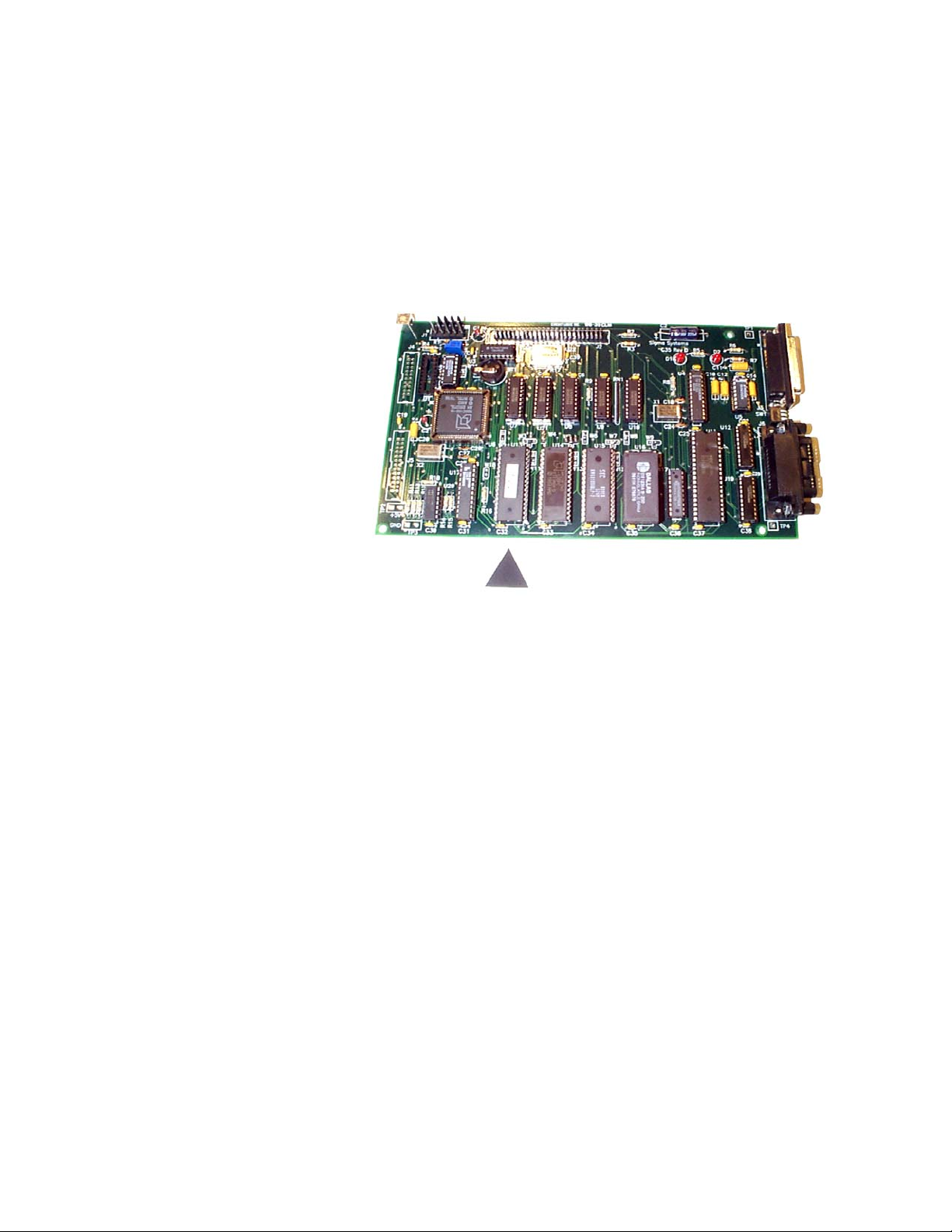
The firmware EEPROM
is located on the digital or
“A” board, the same board
that has the EIA-232 and
GPIB connectors on the
end. The location of the
firmware EEPROM is
shown by the triangle
pointer. The EEPROM
socket is labeled U13. Make certain that the end of the EEPROM with the notch
or notch mark is toward the inside, or center, of the board.
Note that it is possible to remove and replace the firmware EEPROM without
disassembling the C4. If you lay the controller upside down, and look at the
digital board from the bottom, the firmware EEPROM is the first large chip from
the front of the controller. You will not be able to see the U13 label, but you can
see the C32 label on the small capacitor located next to the firmware EEPROM
socket. Using a small flat bladed screwdriver or chip removal tool, carefully pry
the old EEPROM from it’s socket. Try to keep the chip as flat as possible while
removing it to prevent damage to the pins or socket. When replacing, keep the
replacement EEPROM flat to the socket, make sure all pins are started in their
respective receivers in the socket, then press the chip firmly into place.
3.2.2 Upgrading Firmware by Uploading through C4 Serial Port
Note: CC-3.5 controllers with version 7.0.0 firmware or earlier have battery
backed RAMS for non volatile storage. These units MUST have the BBRAM
replaced with an EEPROM before newer firmware is installed.
C4 Manual Rev 7.5.2
25
Page 26

Use a DOS bootable diskette and a PC type computer to load the new firmware
through the C4's serial port. You can obtain the required diskette from Sigma
Systems for a fee, or you can provide your own DOS bootable diskette and obtain
the necessary files for the upload process from the Sigma Systems site on the
Internet. The Internet address for this site is:
www.SigmaSystems.com
The download file, SSUPxxxx.EXE, may contain specific instructions that replace
the instructions in the next paragraph. After downloading the file, copy it to an
otherwise empty DOS bootable diskette and run SSUPxxxx.EXE. This file is a
self extracting ZIP archive that will install all the files you need onto the diskette.
Check for the presence of a README.TXT file on the diskette for instructions that
supplement or supercede these instructions.
Making the physical connection for upload
To upload firmware to your C4, you will need to connect the C4 to a DOS bootable
PC compatible computer using a straight-through, or modem type serial cable.
The C4 is configured as DCE (Data Communications Equipment). Therefore, do
NOT use a “null modem” type serial cable that has pins 2 & 3 crossed. Connect
the cable to either COM1 or COM2 on the PC and to the female DB25 connector
on the back of the C4.
Running the upload software on the PC
After you run the SSUPxxxx.EXE file on your DOS bootable diskette you are
ready to run the software. Place the floppy in the “A” drive of the PC and turn on
or reset the PC to allow it to boot from the floppy. Follow the instructions on the
screen. Note that the menu will allow you to do successive uploads without
restarting and will allow you to change serial ports as you do so. Users who will
be uploading to a number of controllers in one session will find that this feature
saves some time.
If the uploads are being done on a bench (as opposed to leaving the controller in
it’s chamber or platform housing), be certain to follow all precautions about
removing all power before removing the controller and about taking care to use
proper anti-static procedures when handling the controller. Be certain that the
bench has a properly grounded anti-static surface.
If you are going to upload firmware into many controllers successively in a bench
environment, you can use a PC with two serial ports (COM1 and COM2) and two
serial cables. You can then have the upload program alternate serial ports for the
26
C4 Manual Rev 7.5.2
Page 27

uploads so that you can upload to one controller while connecting and
disconnecting the other.
Starting the upload on the C4
When the PC is ready, turn the C4 controller on. During the 1 second display of
the model number, rapidly press <CLEAR/PROG> three times. The display will
read:
rs load
The firmware upload should begin immediately. The PC will indicate when the
load is complete.
If you have difficulties, see the trouble shooting information in Section 9.7.8.
3.3 Restoring Setup Parameters to Default Values
Note: The default values are very generic. They are not the values that were
likely in the controller when it was shipped from the factory. After completing
this procedure, please check each value to make certain that it is appropriate.
To restore the default values to the setup parameter table, turn the controller off,
then back on. During the 1 second in which the controller model is displayed,
press <CLEAR/ENTRY> very quickly 3 times. The display should then read
su res
Press <ENTER> to confirm that you want restore the default values. (Any other
key will abort the process). The display should then read
ee busy and then su done
Turn the controller off, then on again to resume operation with the new values.
The first time the controller is turned back on after restoring the default setup
parameters, the display will show
turned to SETUP. (You may see an ee busy display and model number
and/or firmware version number at this time.) The controller forces you to SETUP
mode before it will function as a reminder that the default values have been
loaded and that the parameters needed for your operation have not yet been set.
all res . The mode switch must then be
C4 Manual Rev 7.5.2
27
Page 28

When you have set the necessary parameters for your needs, you are ready to go
to LOCAL, PROGRAM, or REMOTE mode.
28
C4 Manual Rev 7.5.2
Page 29

3.4 Fahrenheit Operation
The C4 can use either Celsius or Fahrenheit temperature scales. Celsius is the
default mode. When the controller is operating in Celsius mode it’s behavior is
identical to the model CC-3 controller. When the controller is operating in
Fahrenheit mode, both the displays and the bus communications are different.
These differences are intentional and designed to prevent errors that might arise
from a user using setpoints in one scale while the controller is operating in the
other scale. Note, however, that there is no difference in the Program mode
programming operation of the C4 when operating in either Fahrenheit or Celsius
mode. It is incumbent upon the user to notice the differences in the temperature
displays and program accordingly.
To change the temperature scale, use SETUP mode (See Section 8) to access setup
parameter F16. Select either of these field values:
0 Celsius
1 Fahrenheit
When in Fahrenheit mode, temperature displays have an “F” following the probe
identifier on the left side of the display. Example:
p1f 102.4
Likewise, temperature inquires over the bus (PT command - See Section 7.5.7)
will return a string with an “F” as the third byte in the string. The string will
therefore be 1 byte longer than the string returned in Celsius mode. This
difference was intentional as it requires a modification of the parsing routine that
will assure that Celsius and Fahrenheit data are recognized properly. Thus, if the
current probe 1 temperature is 86.7/F, the result of a Fahrenheit mode get
temperature query for probe 1 (query command = PT1) would be
T1F 86.7<CR><LF>
If the temperature at probe 1 was 55.4/C, the same command in Celsius mode
would return
T1 55.4<CR><LF>
During Remote mode operation, the C4 may be queried to determine the current
temperature scale by using the QS, Query Setpoint, command. See Section 7.4.4.
C4 Manual Rev 7.5.2
29
Page 30

3.5 System Operating (Temperature) Range
The C4 controller operates within the limits of the system devices. There are 3
pairs (low-high) of temperature limits that constrain the range of operations.
1. The range of the C4 as it is set at the factory
2 The range of the controlled device (chamber or platform) as
described by setup parameters F25 & F26.
3 The range of the UUT (unit under test) as described by
setup parameters F27 & F28.
Each of these ranges is characterized by a low limit and a high limit. The highest
of the 3 low limits is the low temperature System Operation Limit. The lowest
of the 3 high limits is the high temperature System Operation Limit. In other
words, the controller will respect the most restrictive limits that are described by
the combination of the 3 ranges listed above.
The low and high temperature System Operating Limits define the System
Operating Range. The controller will not accept setpoints outside the System
Operating Range and will report error conditions and stop controlling if the
controlling probe(s) report a temperature too far outside that range.
Note: Probe 1 is always in the chamber airstream or platform and is always
monitored for conformance with the System Operating Range. Probe 2 is
monitored for conformance only if it is being used for control.
3.6 Probe Out of Range Shutdown
When the C4 is actively controlling the temperature of a chamber or platform, it
frequently checks to be certain that the control temperature, as reported by any
active control probe, is within the System Operating Range.
In the event that the temperature reported by the active control probe is more
than 20/C, and less than 50/C, outside the controller’s System Operating Range,
then the controller will presume that a “run away” condition exists. The controller
will turn off all heating and cooling and stop controlling. Blowers will be left in
the condition determined by setup parameter F15 (Blower shut-off mode). The
controller display will show
p1 lo p1 hi
30
C4 Manual Rev 7.5.2
Page 31

“LO” indicates that the reported temperature was 20-50/C below the System
Operating Range. “HI” indicates that the reported temperature was 20-50
above the System Operating Range. The number following the p is the number of
the probe that reported the excessive temperature.
In the event that the control temperature reported by the active control probe is
more than 50/C beyond the System Operating Range, the controller will presume
that the operation of the probe has been compromised by an open or shorted
circuit. The controller will turn off all heating and cooling and stop controlling.
Blowers will be left in the condition determined by setup parameter F15 (Blower
shut-off mode). The controller display will show
/C
p1 err p1 -err
The minus sign in the display indicates that the reported temperature was below
the System Operating Range and the absence of the minus sign indicates that it
was above the System Operating Range.
Note that because the C4 will report a hi or lo condition and stop controlling
for an error of 20-50/C, the only events that will typically trigger an err or -
err
open circuit (err) or short (-err ).
3.6.1 Effect of Probe Correction on Out of Range Shutdown
Any adjustments to the probe readings made by the Software Probe Correction
feature (See Section 3.8) will not affect system over/under temperature shutdown
operations. The raw (uncorrected) probe readings for the current active control
probe(s) are used for the system health monitoring.
3.6.2 Probe Out of Range Shutdown Reported in Error/Status String
Any Probe Out of Range Shutdown will set a bit in Byte 03 of the Error/Status
String. See Section 7.8.3 for specific bit assignments.
3.6.3 Clearing a Probe Out of Range Shutdown
condition is a instantaneous failure of the sensing circuit, most likely an
C4 Manual Rev 7.5.2
31
Page 32

The Probe Out of Range Shutdown condition can be cleared by pressing
<START/STOP> in Local or Program mode, by rotation the mode switch on the
front panel to a different position, or by issuing a Device Clear in Remote mode.
3.7 Internal Error Shutdown Conditions
The C4 monitors system health by keeping track of four internal areas; they are:
Processor health Tracked by watchdog timer
Memory condition Checked at startup
Setup parameter integrity Checked continuously
IEEE-488 bus integrity Checked continuously
The first three items, above, are discussed in sub sections below. The IEEE-488
bus controller is automatically reset if a problem is detected. No message to the
user is generated as no data is typically lost in the process.
3.7.1 Watchdog Timer
Should the system become locked due to corruption that causes the processor to
continuously malfunction, an independent watchdog timer will cause a full system
reset. After a watchdog reset, the display will show
res err
When this occurs, the mode switch must be turned to the OFF position, then back
to the desired mode to clear the reset message and continue operation. Internal
memory will be the same as it was when the shutdown condition occurred.
3.7.2 Memory signature checking
Each time the C4 is powered up, the system checks a series of memory signature
bytes to test the integrity of system memory. If the signature bytes are not
correct, the system assumes that memory has been compromised. If this should
occur (a normal event any time a memory chip is replaced) all of system memory
is reinitialized. All program steps for Program mode are reset to their default
values, and all setup parameters are reset to their default values. The display
will show
32
all res
C4 Manual Rev 7.5.2
Page 33

The mode switch must be subsequently turned to the SETUP position to clear the
display and resume normal operations. Be sure you remember to restore any
setup parameters that have been changed by the system reset.
3.7.3 Setup parameter integrity checking
Each time the system must rely on a system setup parameter the condition of the
setup parameter table is checked against a replica that the system stores in
another place in memory. If there is any difference between the two copies of the
parameter table, the system will try to determine which table is correct and
restore the incorrect copy. If restoration is not possible, the system will turn off
all heating and cooling, reinitialize the setup parameters to their defaults, and
display
su err
The mode switch must be subsequently turned to the SETUP position to clear the
display and resume normal operations. Be sure you remember to restore any
setup parameters that have been changed by the system reset
3.8 Software Probe Correction (Calibration)
The C4 will allow you to enter data via Setup or Remote mode that will correct
any anomalies in the temperature readings and control at two points. Such
adjustments are sometimes necessary to optimize accuracy at a particular
temperature, or to compensate for differences between raw probe temperature
data and actual temperatures.
Note: The purpose of Software Probe Correction is to allow precise calibration at
two points near the critical points of the user’s testing scheme. It does not replace
the hardware calibration process, nor should it. A number of system health
checks as well as process limits are based upon the raw, or uncorrected,
temperatures reported by the probes. It is important to optimize the hardware
level calibration before using this software calibration method.
Software probe correction is achieved by entering four temperatures, U1, C1, U2,
& C2, for each probe into the setup parameter table. U1 & U2 are the
uncorrected, or displayed, temperatures at two points. C1 & C2 are the corrected,
or actual, temperature at those same two points. Thus to make a correction using
ice water (0/C) and boiling water (100/C) when the display shows 2.3/C for the ice
water and 99/C for the boiling water, the user would enter the following:
C4 Manual Rev 7.5.2
33
Page 34

U1 2.3
C1 0
U2 99
C2 100
The C4 will then calculate a new slope and offset for the entire probe curve. All
temperatures reported by the corrected probe will be adjusted by applying this
new slope and offset to the raw temperature data reported by the probe.
Note: Software probe correction is done separately for each probe. The following
table shows the U1, C1, U2, C2 setup parameter assignments:
Probe 1 Probe 2
U1 F17 F21
C1 F18 F22
U2 F19 F23
C2 F20 F24
Entering these parameters via Setup mode is discussed in Section 8.7
Changing these parameters “on the fly” in Remote mode is discussed in Section
7.6.1
3.9 Status and Error Reporting
There are three sources for error and status information:
The Status Byte CC-3 compatible
The Error Byte CC-3 compatible
The Error/Status String
(64 bytes) CC-3.5 & C4 only
The Status Byte and Error Byte are bit mapped single bytes of data. The Error
Byte and the EIA-232 version of the Status Byte are replicated in the Error/Status
string. Maintaining the separate Error Byte allows CC-3 programs to run
properly on the C4. Their interaction with the SRQ error system is important for
all controllers. Here’s how it works:
When an error occurs, the appropriate bit is set in the Error Byte. Setting a bit in
the Error Byte, in turn, sets the error bit in the Status Byte. Setting the error bit
in the Status Byte sets the SRQ. The SRQ will also be set if either Interval
Complete or Setpoint Reached in the Status Byte are set.
34
C4 Manual Rev 7.5.2
Page 35

Some errors, especially those unique to the C4, are only defined in the
Error/Status String. In the event of one of these errors, bit 1 of the Error Byte
(this bit was not used by the CC-3) is set to indicate an extended error. The
Status Byte and SRQ are thus set as well.
The Error/Status String is a bit mapped 64 byte string (512 bits) that contains
both “event triggered” and “status monitoring” information. A complete
description of the Error/Status String and it’s behavior can be found in Section
7.8.3.
3.10 Fail-safe System
The C4 is designed to sense the loss of control circuit power due to opening of a
safety limit switch such as those supplied with all Sigma chambers and thermal
platforms. If the controller is in the RUN mode and the fail-safe is tripped, the
controller will stop controlling and display
display. It will also report the fail-safe tripped condition over the computer bus
interface if in use. In order to re- establish normal operation, the failsafe system
on Sigma chambers and thermal platforms requires that power be cycled off then
on in addition to the out of range temperature condition subsiding. Use the rotary
Mode Switch on the controller front panel. Turn the switch to OFF to clear the
fail-safe condition.
If the controller is to be used independently of a Sigma Systems temperature
chamber or thermal platform, connect pins 10 & 11 of the 12-pin power plug to pin
3 for 120 volt operation. In the case of 208-240 volt operation connect pins 10 &
11 to pin 6 through a 56kS ½ watt resistor. Opening this connection will cause
the above described failsafe condition.
fl safe on the digital LED
C4 Manual Rev 7.5.2
35
Page 36

36
C4 Manual Rev 7.5.2
Page 37

4. INTELLIGENT 2 PROBE CONTROL
(Probe Averaging)
(Not in this release. Available in next release, without charge. Contact Sigma
Systems to receive a revised firmware EEPROM.)
Intelligent 2 Probe Control allows the internal temperature of the UUT (Unit
Under Test) to be used in the temperature control algorithm. Both the primary
probe, located in the chamber airstream or in the platform, and the secondary
probe, typically located inside the UUT, are used to provide a chamber or platform
response that can accelerate testing while respecting the absolute and relative
limits of all the affected components.
Common single probe control strives to maintain the setpoint temperature in
either the chamber airstream, or at the platform surface. If the UUT is massive,
or is a poor thermal conductor, the internal temperature of the UUT can lag the
chamber or platform temperature considerably. If, as a result of measuring the
chamber air stream or platform temperature only, the test is terminated too
quickly, the UUT may not have actually achieved the desired setpoint test
temperature. Conversely, using a second probe, buried inside the UUT, to control
the temperature may achieve better UUT interior temperature control, but it will
do so at the risk of extreme temperatures in the chamber or on the platform and
thus at the UUT surface as well.
Intelligent 2 Probe Control is designed to achieve the setpoint temperature inside
the UUT (probe 2) either as quickly as possible, or at a controlled ramp rate, while
always respecting the limits of the controller, chamber or platform, and UUT. The
user may specify the absolute limits of the UUT as well as limit thermal shock by
specifying a proportionally applied maximum temperature differential for the
UUT skin to core temperature. Intelligent 2 Probe Control will maximize speed in
achieving internal UUT setpoint temperatures, while, at the same time,
controlling the thermal stress on the UUT.
Note: For the balance of this section, the description of Intelligent 2 Probe Control will
be related to operation of temperature chamber. All of this information applies to
thermal platforms as well, but they are not mentioned further to make the text easier to
read.
C4 Manual Rev 7.5.2
37
Page 38

4.1 How Intelligent 2 Probe Control functions
Intelligent 2 Probe Control takes advantage of the fact that increasing the
temperature differential between two objects increases the rate of heat transfer
between them. For instance, if a thick and heavy object is to be heated from 0/ to
100/, and the object is placed in a temperature chamber with a 100/ internal air
stream temperature, the temperature of the object will rise quickly at first
because of the large differential between the temperature of the chamber air
stream and the object.
However, as the object continues to absorb heat, the differential decreases and the
rate of heat transfer decreases. The closer the object’s temperature approaches
the air stream temperature, the more slowly the object absorbs heat. To maintain
the thermal transfer efficiency that existed early in the warming process (when
the differential was, for example, 80/), the air stream would have to continually
get warmer as the object heated. When the object was 20/, the air would have to
be 100/, when the object was 50/, the air would have to be 130/, when the object
was 80/, the air would have to be 160/, etc. Heating efficiency can be substantially
improved by this method.
However, because our object is thick and heavy, there likely is a large
temperature differential between the surface temperature of the object and the
core temperature that we are measuring. Even though the object’s core is only 80/
at some point in this process, the surface temperature, exposed to 160/ air, may
well be much higher. In fact, if the object is a poor thermal conductor, the surface
temperature may approach the air temperature... in this example, 160/.
While we would like to have our object’s core temperature increase as quickly as
possible, inducing a surface temperature that is 60/ over the setpoint may be more
than the object can tolerate. If we knew, however, that the object’s surface could
tolerate 130
/, then we could use an air stream temperature of 130/ - but no more -
to speed the transfer of heat into the object.
When the object’s core temperature started to approach the setpoint, we could
reduce the amount of over heating of the air and object surface. The closer the
core temperature got to the setpoint, the less overheating would be applied.
Eventually, just as the core temperature reached the setpoint, the amount of
overheating would be zero. The ramp rate of the core of the object would have
been maximized without exposing any of the object to temperatures exceeding it’s
tolerance.
There is one more consideration. You may want to achieve an object core
temperature as quickly as possible to improve production testing efficiency, but
you may want to not apply thermal differentials that will “shock” the object you
are testing. In fact, the object may have more tolerance for differentials when hot
38
C4 Manual Rev 7.5.2
Page 39

than cold, or visa versa. To properly protect your object you need to be able to
constrain the air temperature in the chamber (and thus the surface temperature
of the object) such that the difference between surface temperature and the core
temperature does not exceed some difference the object can tolerate. It would be
useful to be able to specify such a differential tolerance for both the high and low
thermal limits of the object.
4.2 Preparing for Intelligent 2 Probe Control
The Sigma Systems C4 controller, using Intelligent 2 Probe Control, provides
temperature control based upon all of the factors discussed above. The process is
very simple. You will first need to set all the limits that the C4 will need. Then,
you use the normal commands or operations, in Local mode, Program mode, or
Remote mode, to go to temperatures, ramp to temperatures, hold temperatures,
etc.
The limits for the UUT temperature extremes are set in Setup parameter fields
F27 (lower limit) and F28 (upper limit). These values can be set in Setup mode as
described in Section 8, or by using the SL (Set UUT Temperature Limits)
command from Remote mode as described in Section 7.6.4.
The UUT temperature differential limits are set in Setup parameter fields F29
(lower differential limit) and F30 (upper differential limit). These values can be
set in Setup mode as described in Section 8, or by using the SD (Set UUT
Temperature Differential Limits) command from Remote mode as described in
Section 7.6.5.
Note that the low limit you set is the allowable differential between the air stream
temperature (platform surface temperature) as measured by probe 1 and the UUT
core temperature as measured by probe 2 at the UUT low temperature limit as
described by Setup parameter F27. Likewise, the high limit you set is the
allowable differential between the air stream temperature (platform surface
temperature) as measured by probe 1 and the UUT core temperature as measured
by probe 2 at the UUT high temperature limit as described by Setup parameter
F28. For example:
If the lower UUT limit (F27) is set to -100
limit (F29) is set to 60
/, and the setpoint is set to -80/ while the UUT is
/ and the the lower differential
considerably warmer than that, then the controller will try to take the
temperature of the chamber down below the setpoint (max -100
the down ramp. However, because the differential limit is 60
/) to speed
/, the
controller will be constrained to keep the amount of thermal lead (difference
between probe 1 in the air stream and probe 2 in the UUT core), to 60
/. The
C4 Manual Rev 7.5.2
39
Page 40

air stream temperature, based upon this 60/ limit, would not be allowed to
drop to -100
/ until the UUT core temperature had reached -40/
The same rules hold true for the high end of the UUT range except that the high
differential limit (F30) is applied at the high limit of the UUT range (F28).
For UUT core temperatures between those limits, a proportional differential limit
is calculated by the C4 based upon the limits specified at the extremes. For
Example:
If the lower UUT limit (F27) is set to -100
/ and the the lower differential
limit (F29) is set to 60/, and the upper UUT limit (F28) is set to 200/, and
the upper differential limit (F30) 20
temperature of -25
/ would be 50/.
/, the differential limit calculated for a
Important: Intelligent 2 Probe Control, like normal control using probe 1 or
probe 2, is constrained by the limits of the controller range and the
chamber/platform operating temperature limits (F25 & F26). If a probe correction
has been implemented for either or both probes (F17 - F24), those adjustments
will be used as well. It is imcumbent upon the user to be certain that they are
aware of these settings and their potential for interaction.
4.3 Using Intelligent 2 Probe Control
Once all of the necessary settings have been made and verified, using Intelligent 2
Probe Control is very easy. To use Intelligent 2 Probe Control, set the probe
number to zero (0). Intelligent 2 Probe Control will be used in any mode, Local,
Program, or Remote, if the probe number = 0.
40
C4 Manual Rev 7.5.2
Page 41

5. LOCAL MODE ( Basic Operation )
The C4 Local mode of operation provides simple control of the chamber or
platform through the front panel controls. In this mode, a single setpoint is
entered from the front panel and the controller will attempt to have the chamber
or platform reach and hold that temperature. In local mode the compressor of
mechanically refrigerated units can be turned on or off using the <REFER> button
on the front panel.
The controller can be set to automatically start controlling at the last used
temperature upon startup by setting the controller to the AutoStart mode. See
AutoStart mode description, Section 8.4.
The circled numbers on the front panel guide the user through the sequence for
the basic operation of changing the setpoint. The reasoning for each keystroke is
as follows:
1. Display control setpoint temperature.
2. Clear the existing setpoint value.
3. Key-in control probe number (only if 2 probes defined in setup parameter
F1) & new setpoint.
4. Commit new setpoint entry.
5. Display current chamber temperature.
If controller RUN LED is not ON press <START/STOP> to begin controlling
at set temperature.
5.1 Displaying Temperature
The temperature may be displayed at any time by pressing the <DISP/TEMP> key.
The format of the display is
Pn TT.T Example:
PnF-TTT.T Example:
p1 - 102.6 (Celsius)
p1f- 102.6 (Fahrenheit)
where n indicates from which probe the reading originates and the -TTT.T
indicates the numeric temperature. In single probe mode, n is always 1. In two
C4 Manual Rev 7.5.2
41
Page 42

probe mode, n can be 1 or 2 as the temperature display toggles between probe 1
and probe 2 with each press of the Display Temperature <DISP/TEMP> key. If
Intelligent 2 Probe Control is implemented (probe number set to 0), the display
will rotate from probe 1 to probe 2 to probe 0 (average), then back to probe 1, etc.
with each press of <DISP/TEMP>. The temperature is displayed to the nearest
tenth of a degree C. although internal temperature values are kept at a much
higher precision. The value is rounded so that a display of 30.2 means a
temperature between 30.15 and 30.24. Fahrenheit values display an F after the
probe number.
5.2 Displaying and Changing the Setpoint
The setpoint may be displayed by pressing the Display Control key <DISP/CNTL>.
The format of the display is
Sn TT.T Example:
SnF-TTT.T Example: s1f- 102.6 (Fahrenheit)
where n is the probe used for control. Upon entering the LOCAL mode from the
PROGRAM REMOTE or SETUP mode, the control probe defaults to 1 and the
setpoint is erased. If the setpoint has been erased, the “no setpoint” message
displays in lieu of the setpoint temperature. Example:
s1 - 102.6 (Celsius)
s1 nsp s1f nsp
To change either the setpoint temperature or the control probe (of a 2 probe
configuration only), use the following procedure:
1. First display the setpoint using <DISP/CNTL>.
2. Press <CLEAR/ENTRY> to clear the current value from the display. If
single probe mode is in effect,
display indicating the control probe must be 1. If two probe mode is in
effect, the probe number is also cleared.
s1 or s1f will appear at the left of the
42
3. If the probe number is erased, (in two probe mode) enter the controlling
probe desired, either 1 or 2 for control by probe 1 or probe 2, or enter 0 for
Intelligent 2 Probe Control (See Section 4). If in single probe mode, ignore
this step.
C4 Manual Rev 7.5.2
Page 43

4. Enter a setpoint temperature using the numeric, decimal point and sign
keys. Numbers may be entered with a maximum of 1 decimal place.
Pressing the sign <+/-> key will toggle the value between positive and
negative. Positive values will have no indication, negative values will show
a minus (-) sign to the left of the temperature display.
5. Errors may be corrected by simply pressing <CLEAR/ENTRY> and rekeying the entry prior to pressing <ENTER>.
6. After the number is keyed in, press <ENTER> to commit the entry and
store it as the new setpoint.
7. The controller will remain in the RUN mode if the rotary switch has not
be changed and <START/STOP> has not been pressed.
Note: If the setpoint entered is not within the System Operating Range (See
Section 3.5), an error message will be displayed and the setpoint will not be
stored. If the requested setpoint is below the System Operating Range, the error
will be preceded by a minus sign (-). Examples:
sor -sor
When this message is displayed, press <CLEAR/ENTRY> to return to setpoint
entry mode.
TIP: It is not necessary to stop the controller from controlling the chamber or platform
to change the setpoint. The setpoint may be changed at any time, even while the
chamber or platform is being actively controlled.
5.3 Controlling to a Setpoint
The controller will start to control to the specified setpoint when <START/STOP>
is pressed. The RUN LED will light to indicate the control process is active. A
subsequent press of <START/STOP> will cause the controller to stop controlling
and the RUN LED will be extinguished. Unless disabled through setup parameter
F15, Blower Shut-off Mode (See Section 8.5), the chamber blowers will continue to
run regardless of RUN status. If <START/STOP> is pressed before a setpoint has
been set, the following error will be displayed:
sp err
C4 Manual Rev 7.5.2
43
Page 44

5.4 Compressor Control (mechanically refrigerated unit control only)
The compressor of a system employing mechanical refrigeration can be manually
toggled at any time during local mode controlling operation by pressing the
<REFER> button. The REFER LED on the front panel indicates the state of the
refrigeration compressor control port. The port is shut off when controlling action
is stopped by pressing the <START/STOP> button and restarted if
<START/STOP> is pressed again before the rotary switch is moved to a mode
other than Local or Off.
The controller can be configured to not respond to front panel <REFER>
(compressor) ON/OFF commands. See SETUP mode, Section 8 - setup parameter
F13.
44
C4 Manual Rev 7.5.2
Page 45

6. PROGRAM MODE
The Program Mode allows more complicated front panel control than the Local
Mode. The Program Mode allows a temperature control program to be entered
into the controller memory for subsequent execution as required. Up to 100
program steps may be entered. Multiple programs may be entered and executed
as long as the total number of steps in all programs does not exceed 100.
Programs are stored in non-volatile EEPROM memory. See Appendix 9.1 for
Sample Programs.
6.1 Description of a Program Step
Each program step has five data parameters, called substeps. The program
substeps are numbered 0-4. Except for special command steps (see Section 6.8),
each substep has a dedicated function as follows:
Substep 0 is a setpoint temperature.
Substep 1 is the ramp time.
Substep 2 is the hold time.
Substep 3 is the next step to be executed. If this substep is specified as
100, the program will terminate after execution and the
display will show "End".
Substep 4 is the probe used for control. It can be specified as 0, 1, or 2 to
select the probe or mode to be used for temperature control, or
3 to 7 to effect special commands (see Section 6.8).
When displaying program steps on the LED display, the program step.substep is
displayed at the left side of the display and the data associated with that program
step.substep is displayed on the right as follows:
06.0 - 30.5
The example above shows step 6, substep 0 contains the temperature data -30.5
Each program step contains all five substeps, regardless of whether or not each
step is used. Therefore, a complete program step is as follows:
C4 Manual Rev 7.5.2
45
Page 46

6.1.1 Format of a Program Step
FORMAT OF A STEP
substep
)))))),
step )))0, * -----------data------------
** *
00.0 -TTT.T - temp (setpoint)
00.1 HH.MM - ramp time
00.2 HH.MM - hold time
00.3 NNN - next step
00.4 P - control probe
where: step is the current program step number (00 - 99)
substep is the current program substep (0-4)
TTT.Tis the setpoint temperature displayed to the nearest .1°C
HH is hour(s) (00 - 99) for ramp or hold
MM is minute(s) (00 - 59) for ramp or hold
NNN is the next program step number (00 - 100) to execute
P is the number of the probe (1 or 2) to use for control or...
P is the special command indicator (values of 3 thru 7)
(See 6.8 for details)
The simple graph at the right shows a
typical ramp & hold scenario. In this
example the user wants to ramp from
0° to 78° in 20 minutes and then hold
78° for the next 20 minutes. A single
program step will accomplish both
tasks.
The sample program step below will
pass control to program step 6 when it
has completed.
46
C4 Manual Rev 7.5.2
Page 47

Program step.substep Data Effect/Purpose
05.0 78.0 Sets temp setpoint to 78°
05.1 00.20 Sets ramp time to 20 minutes
05.2 00.20 Sets hold time to 20 minutes
05.3 6 Sets step 6 as next step to execute
05.4 1 Selects probe 1 for active control
6.1.2 Maximizing Ramp Speed & Other Ramp Considerations
When a ramp time is specified in a program step, the controller attempts, within
the limits of system capability, to achieve a linear temperature change rate such
that the setpoint is achieved precisely at the end of the ramp period. If an
insufficient ramp time is specified, some of the hold time will be “borrowed” to
allow the ramp to setpoint to complete.
To achieve the maximum ramp rate, set the ramp time (substep 1) to 00.00 and
the hold time (substep 2) to 99.00. A program step with a ramp time of 00.00 and
a hold time (substep 2) of 99.00 will cause the controller to achieve the setpoint as
quickly as possible then immediately execute the next step. If a specific hold time
following ramping at maximum ramp rate is required, then use two steps. Both
steps should specify the same setpoint. The first step should have a ramp time of
00.00 and a hold time of 99.00. The second step should have a ramp time of 00.00
and the desired hold time.
Note & Warning: A program step with specified ramp and hold times will
terminate at the end of the specified time (ramp time + hold time), regardless of
whether the controller was able to achieve the setpoint. On the other hand, a
maximum speed ramp step (substep 1 = 00.00 & substep 2 = 99.00) will not
advance to the next step until and unless the setpoint is achieved. If the unit
under test generates or absorbs heat in a manner that prevents the test
environment from ever becoming stable at the setpoint, the program will “hang”
on such a step as it will not advance to the next step unless it can stabilize the
platform or chamber at the setpoint.
A program step with a ramp time of 00.00, a hold time of 00.00, and a probe
number of either 1 or 2 is a null program step. A null program step has no effect
on the temperature setpoint of the chamber. It is used to fill an unneeded step in
an existing program.
C4 Manual Rev 7.5.2
47
Page 48

6.2 Clearing Program Memory (Reinitializing program steps)
When the controller is shipped from the factory, all program steps are initialized
to their default values as shown below. To create a usable program for the
controller to run, the user enters replacement values in those program steps to be
used. All program steps are retained in memory even during power down of the
controller. When it becomes necessary to clear all of the user programmed steps
from memory, use the CLEAR PROGRAM <CLEAR/PROG> key on the keyboard.
All program steps will be reinitialized to their default values. The procedure
below will reinitialize all program steps to their default values.
To reinitialize all program steps to their default values, press <CLEAR/PROG> to
display the clr warning message on the display, then press <CLEAR/PROG>
again to return all program steps to their default values as shown below. If ever
you accidentally press <CLEAR/PROG> and see the clr warning on the
display, you may press any key except the <CLEAR/PROG> key abort the memory
clearing process.
Note: The two presses of <CLEAR/PROG> must be at least ½ second apart. This
assures that the two presses were intentional and prevents accidental program
erasure. Once program memory has been erased, it cannot be restored.
When the program memory is reinitialized, each of the 100 program steps is
initialized to the following default values (null program steps):
Substep 0 30.0 (30 degrees C.)
Substep 1 00.00 (Ramp time zero)
Substep 2 00.00 (Hold time zero)
Substep 3 SS+1 (Next sequential step)
Substep 4 1 (Active Probe one)
6.3 Displaying Program Steps (not during execution)
To display the program steps, press the DISPLAY CONTROL key <DISP/CNTL>.
Unless you are already in program mode and have just displayed a different
program step, step 0, substep 0 (the setpoint for step zero) will be displayed. Each
subsequent press of the <DISP/CNTL> key will cause the display to increment to
the next program substep.
To display a specific program step, enter a one or two digit step number directly
after any press of the <DISP/CNTL> key and then press the <DISP/CNTL> key
again to display the entered step.substep 0.
48
C4 Manual Rev 7.5.2
Page 49

6.4 Entering or Changing a Program Step
There is no difference between entering a program step and modifying an existing
one.
To change any part of the program, first display the current step by pressing
<DISP/CNTL>. If you wish to make changes to a step other than the current step,
enter the 1 or 2 digits for the step number (0-99) and press <DISP/CNTL> again.
Substep 0 of the desired step will now be displayed.
For each substep displayed, you may change the current value or accept the
current value. To accept the current value and display the next substep, press
<DISP/CNTL>.
To change the current value, press <CLEAR/ENTRY> to clear the old value then
enter the desired new value. Pressing the <ENTER> key stores the new substep
value and advances the display to the next substep. Only valid changes are
allowed. Subsequent and steps and substeps may be altered in the same manner
by pressing <DISP/CNTL> until the desired step is displayed.
Note: The program may only be changed when the program is not executing (run
LED is off) and the controller is in the program mode (Mode swith set to
PROGRAM).
Appendix 9.3 contains a template form for writing programs.
6.5 Insert Program Step
To insert a step before an existing step:
1. Enter the step number to be moved up and press <DISP/CNTL>
2. Press <CLEAR/ENTRY>
3. Press <ADV>
The display shows “
number for the current step.
4. Press <ENTER> to move the current and all higher steps up 1 step and
insert a new step at the current step number.
The current step will then be the new step with default values. New
step.substep 0 will be displayed so you can enter your data for that step.
Note that inserting a step pushes old step 99 out of memory.
ins nn”, where nn is the new incremented step
C4 Manual Rev 7.5.2
49
Page 50

6.6 Delete Program step
1. Enter the step number to be deleted and press <DISP/CNTL>
2. Press <CLEAR/ENTRY>.
3. Press <CLEAR/ENTRY> again.
The display shows “del nn”, where nn = step number to be deleted.
4, Press <ENTER> to delete the step and move all higher steps down one step.
6.7 Running (Executing) a Program
To start program execution, the beginning program step of the program to be run
must be displayed. Displaying a specific program step is covered in Section 6.3.
With the first step of a program displayed, press <START/STOP> to begin
program execution at that step. The program will continue to execute until it
reaches program step 100 where it will display end and wait for action from the
operator.
Running programs may also be stopped at any time by pressing <START/STOP>.
After a program has been stopped in this manner, pressing <START/STOP> again
will cause the program to continue executing from the beginning of the step it was
executing when it was stopped. Important: If the refrigeration compressor was
on when the program execution was interrupted in this way, it will be restarted
when program execution is restarted.
At the end of a program, the controller will not turn on further heat or cool,
however, the chamber blowers will remain on unless blower shutoff mode has
been enabled(see Section 8.5). The blowers can be turned off manually by an
operator using the front panel mode switch. Set the switch to OFF to turn off the
blowers. The refrigeration compressor (mechanically refrigerated models only)
will be turned off when a program completes.
IMPORTANT: If you are controlling an chamber or platform with optional solid
state relay power control, including units with compressor control, please read
Section 6.8.4 at this time.
CAUTION: Chamber temperatures can exceed 70°C, without heaters energized,
if high velocity blowers have been installed. If this presents a problem, be sure
the test load is removed promptly at the end of the program run, or enable blower
shutoff mode (see Section 8.5) to have blowers not run on at the end of a program
execution.
50
C4 Manual Rev 7.5.2
Page 51

6.7.1 Program Run Time Information/Considerations
When a program is running, the display shows the currently executing program
step number on the left and the total amount of remaining run time for that step
on the right. The time displayed is the sum of any remaining ramp time and/or
hold time. The temperature may be displayed by pressing <DISP/TEMP> while
the program is running. Pressing <DISP/CNTL> will restore the display of the
current step number and the time left in the step.
Programs may be designed to run continuously by specifying the next step to be
any previous step of the program. In this way, step 100, the end, is never reached.
The program must then be stopped by the operator pressing the <START/STOP>
key. Controlled looping is also possible. See 6.8.1.
Multiple programs may be stored in memory since a program may be started from
any step and terminates with any step specifying 100 as its next program step. It
is the operator's responsibility to keep a record of the beginning program step
number for each program in memory.
6.7.2 Run Time Pre-read Errors
When a program is started by pressing <START/STOP> with the first step of the
program displayed, the C4 will pre-read all the program’s steps in the run time
execution sequence. During the pre-read, the C4 checks all steps for errors so that
the user can solve any problems immediately rather than having them occur later,
during program execution. The pre-read makes certain that the program to be
run does not call for probe 2 use when only one probe is defined by setup
parameter F1, that all loop commands contain valid loop counters, and that all
setpoints requested are within the System Operating Range. In each case, if an
error is found, the display will show the step number that contains the error on
the left side of the display, and the error message on the right side.
Note that the pre-read will display the first error is finds. If there is more than
one error, each successive error will be shown on the display after the last
displayed error is corrected and a program start is again attempted.
C4 Manual Rev 7.5.2
51
Page 52

No Probe 2 Error
If a program step calls for control by probe 2 when setup parameter F1 = 1
(number of probes) the C4 will generate a No Probe 2 Error. Example
007 nop2
You must either remove the step that calls for probe 2 or enable probe 2 with
setup parameter F1 (See Section 8) before the program will run. See Section 8.3.
Invalid Loop Count Error
If a program step is a loop start step (substep 4, probe value = 3), then the loop
count (substep 0, loop count) must be in the range 1 - 999 integer (no decimal
value). If the number is either not an integer, or is outside the range 1 - 999, the
C4 will generate an Invalid Loop Count Error. Example:
003 loop
The invalid loop count must be corrected before the program will run. See Section
6.8.1.
Setpoint Out of Range Error
If a program step requests a setpoint outside the System Operating Range (See
Section 3.5), the C4 will generate a Setpoint Out of Range Error. The error
message will be preceded by a minus sign (-) if the setpoint requested is lower
than the System Operating Range and will not show a minus sign if the requested
setpoint is above the System Operating Range. Example:
005 sor 005 -sor
Either the setpoint request or one of the temperature ranges that defines the
System Operating Range will have to be changed before the program will run.
52
C4 Manual Rev 7.5.2
Page 53

6.8 Special Commands
There are special commands that use the substep data within a step for different
purposes than normal. These commands are (6.8.1) Creating controlled loops, and
(6.8.2 - 6.8.5) External port controls. In each case only some of the substeps are
used. To enhance program readability, we suggest that you set any unused
substep values to zero.
6.8.1 Controlled Program Looping
The program may be placed into a controlled loop by the use of the PROGRAM
LOOP special command. When the Probe is specified as 3, the Setpoint value is
used as a loop count. This value must be specified as an integer and be in the
range 1 - 999. Each time the Loop Command is reached in the program, the loop
count is decremented by one. As long as the loop count is greater than zero, the
program will execute the step indicated in the Next-Step-Number substep of the
Program Loop step. When the loop count (substep 0) value finally becomes zero,
the step following the Program Loop step is executed.
Example:
Step &
substep Value
07.0 5 Loop count
07.1 0000 (not used)
07.2 0000 (not used)
07.3 1 Loop start step
07.4 3 Identifies this step as a PROGRAM LOOP command
This will loop 5 times from step 1 to step 7 decrementing the loop counter by 1 for
each loop. When the loop counter has reached 0 the program will continue with
step 8.
Notes:
Nested program loops not supported. They may appear to work if you try to use
them, but the loop will never complete and further results are not predictable.
A loop count of 5 (example) will cause the program to execute the loop 5 times. If
the program loop refers to a previously executed step as the loop start step, then
that step will be executed once originally plus the 5 times for the loop, for a total
of 6 times.
Example: If the program that contained the example loop step, above, began with
step 00, then progressed normally through steps 1, 2, 3, 4, 5, and 6 before
C4 Manual Rev 7.5.2
53
Page 54

encountering the loop statement in step 7, then steps 1-6 will already have been
executed once and then again 5 more times as a function of the loop, for a total of
6 times.
6.8.2 External Compressor On
When the Probe (substep 4) is specified as 4, the program step turns the
refrigeration compressor control port on. Substeps 0 - 2 are ignored. Upon power
up, start and stop of program execution, and changing of the mode switch, this
port will be off. The REFER LED on the front panel will indicate when this port is
on or off.
6.8.3 External Compressor Off
When the Probe (substep 4) is specified as 5, the program step turns the
refrigeration compressor control port off. Substeps 0 - 2 are ignored. Off is the
default mode for this port upon power up, start and stop of program and changing
the rotary switch. The REFER LED on the front panel will indicate when this port
is on or off.
6.8.4 Optional Aux/Power Control Port On
When the Probe (substep 4) is specified as 6, the program step turns the optional
aux/power control port on. Substeps 0 - 2 are ignored. Upon power up and
changing of the mode switch, this port will be on. At start and end of program
execution, this port will be automatically set to off.
For special order chambers or platforms equipped with optional solid state relay
to control main power
, this command must be used once at the beginning of a
program in order to turn the chamber or platform on. Note that because this
control will disable all power to a chamber with solid state relay chamber power
control, the normal continuous running of the air circulation fans is disabled
regardless of the state of the Blower Shutoff Mode setup parameter.
Note that mechanically refrigerated chambers or platforms with cryogenic coolant
boost use the Aux/Power Port to control the availability of the cryogenic boost
system. Because the port will be turned off at the start of any program, cryogenic
boost cooling will only be available if this port is turned on.
6.8.5 Optional Aux/Power Control Port Off
54
C4 Manual Rev 7.5.2
Page 55

When the Probe (substep 4) is specified as 7, the program step turns the optional
load control port off. Substeps 0 - 2 are ignored. Upon power up and changing the
rotary switch this port will be on
. At start and end of program execution, this
port will be automatically set to off.
6.9 Common Programming Issues
6.9.1 Step Numbering
Remember that the first step or substep is 0 instead of 1.
6.9.2 Changing Substep Values
When changing a substep value on the right half of the display, you must use the
<CLEAR/ENTRY> key to clear the previous entry from the display before entering
a new value. Then enter the new value by keying on keypad, then press <ENTER>
to store that new value.
6.9.3 Control Ports
Refrigeration compressor and optional aux/power control ports will return to their
default values of On (HI) and Off (LO) respectively upon changing the setting of
the rotary switch. However before the start and after the end of a program they
will both be LO.
C4 Manual Rev 7.5.2
55
Page 56

56
C4 Manual Rev 7.5.2
Page 57

7. REMOTE MODE
Remote mode provides for control of the C4 from a remote computer or terminal
using either standard EIA-232 serial communication or Instrumentation Standard
IEEE-488 (GPIB) communication. Selection of the type of interface is made from
the setup mode, see Section 8.
NOTE: The IEEE-488.2 requirement for lockout of front panel control during
IEEE-488 control is not enabled in this controller. The front panel mode switch
remains active during remote control.
In remote mode, the C4 is controlled externally by sending a 2 character ASCII
command over the bus followed by an optional set of parameters, and ending with
a terminator. For both IEEE-488 and EIA-232 communication, the terminator is
Carriage Return & Line Feed (13,10 decimal) (0Dh 0Ah). For IEEE-488 command
structure, see Appendix 9.4.
7.1 EIA-232 Interface
The controller may communicate remotely through an EIA-232 interface. To use
EIA-232 communication, the interface must be selected for EIA-232 remote
communication in Setup mode. Additionally, the interface must be software
selected for proper baud rate, parity, data bits and stop bits. These are also set
through the keypad in Setup mode and become stored in the non- volatile memory.
See Section 8, Setup Mode.
A female DB-25 connector is provided on the rear panel. The interface is set up as
a DCE with DTR and CTS set always true.
7.2 IEEE-488 Interface
The IEEE-488 interface is implemented as a Talker/Listener without extended
addressing or parallel poll capability. The primary address is selected through the
keypad in Setup mode. A standard IEEE-488 connector is provided on the rear
panel. (See sample commands in Appendix 9.4.)
C4 Manual Rev 7.5.2
57
Page 58

7.3 Command Summary (by functional group)
System Information Queries See Section:
QV Query Firmware Version 7.4.1
QN Query Controller Serial Number 7.4.2
QR Query Controller Temperature Range 7.4.3
QS Query Setpoint & Control Probe Number 7.4.4
QF Query Setup Parameter (binary) 7.4.5
QFA Query Setup Parameter (ASCII hex) 7.4.5
Operation Information Queries & Commands See Section:
RS Request Status Byte (binary) 7.5.1
RSA Request Status Byte (ASCII hex) 7.5.1
RE Request Error Byte (binary) 7.5.2
REA Request Error Byte (ASCII hex) 7.5.2
QE Query Error/Status Flag String (binary 7.5.3
QEA Query Error/Status Flag String (ASCII hex) 7.5.3
QC Query Last Command String 7.5.4
ES Enable SRQ 7.5.5
DS Disable SRQ (Default) 7.5.6
PT
Read Probe n Temperature
7.5.7
Setup Commands See Section:
SC
WP Set PID Constants 7.6.2
BF Blowers off (Enable Blower Shut-Off Mode) 7.6.3
BO Blowers on (Disable Blower Shut-Off Mode) 7.6.3
SL Set UUT Temperature Limits 7.6.4
SD Set UUT Temp. Differential Limits 7.6.5
UP Write Current Parameters to NV Memory 7.6.6
Set Correction for Probe n
7.6.1
System Operation Commands See Section:
SI Select Immediate Execution Mode 7.7.1
SP Select Program Mode (Default) 7.7.2
PN
GT,GTF Go to Temperature 7.7.4
RA, RAF Ramp to Temperature 7.7.5
DL Delay (hold) for Interval 7.7.6
CO Turn Refrigeration Compressor On 7.7.7
CF Turn Refrigeration Compressor Off 7.7.7
TO Turn Aux/Power Port On 7.7.8
TF Turn Aux/Power Port Off 7.7.8
QU Quit Controlling (return to idle state) 7.7.9
Select Probe n for Control
7.7.3
58
C4 Manual Rev 7.5.2
Page 59

7.4 System Information Queries
7.4.1 QV Query Firmware Version
This command returns the current internal firmware release number in ASCII
text in the following format:
QV<space>nnn.nnn.nnn<CR><LF>
Where nnn is the number of each part of the release number, padded on the
left with leading zeros if necessary.
Example:
QV 007.003.001<CR><LF>
The syntax for the command is:
QV<CR><LF>
7.4.2 QN Query Controller Serial Number
This command returns the controller serial number in ASCII text in the following
format:
QN<space>n-nnnnn<CR><LF>
Where the first number n is the number designating the model group (3 for
CC-3.5, or 4 for C4) and the five digits nnnnn following the dash comprise
the sequential part of the serial number.
Example:
QN 4-03376<CR><LF>
Note: When recording or reporting the serial number, always use all 7 digits.
The syntax for the command is:
QN<CR><LF>
C4 Manual Rev 7.5.2
59
Page 60

7.4.3 QR Query Controller Temperature Range
This command returns the controller temperature range in ASCII text in the
following format:
QR<space>thhhh-lll<CR><LF>
where t = C or F
hhh = high limit
lll = low limit\
Example: For standard range controller in Celsius mode:
QR C200-100<CR><LF>
The syntax for the command is:
QR<CR><LF>
7.4.4 QS Query Setpoint & Control Probe Number
This command returns the current setpoint and control probe number as follows:
Sp<space>[-]nnn<CR><LF> For Celsius mode
SpF<space>[-]nnn<CR><LF> For Fahrenheit mode
Where p is the number of the controlling probe and
Where nnn is the current setpoint.
Example: Control with probe 1 to -85/F
T1F -85.0<CR><LF>
Note: If probe number returned = 0, then Intelligent 2 Probe Control is active.
The syntax for the command is:
QS<CR><LF>
60
C4 Manual Rev 7.5.2
Page 61

7.4.5 QF, QFA Query Setup Parameter Value
This command returns the current (SRAM) value of a setup parameter field. QF
requests the data to be returned in binary form, QFA requests the data to be
returned in ASCII text form. The syntax of the command is:
QFnn<CR><LF> QFAnn<CR><LF>
(Query for binary) (Query for ASCII text)
Where nn is a one or two byte ASCII text decimal number of the setup
parameter field to be returned.
For parameters numbered 0 through 16:
If QF is used, the value stored for that parameter is returned as a one byte binary
value in an ASCII string as follows:
QFnn<space><binary byte><CR><LF>
Where nn is the setup parameter number in 2 bytes of ASCII text decimal
(leading zero if required).
If QFA is used, the value is returned in two bytes of ASCII hex in the format 00 in
an ASCII string followed by CR/LF as follows:
QFAnn<space>hh<CR><LF>
Where nn is the setup parameter number in 2 bytes of ASCII text decimal
(leading zero if required) and hh is the ASCII hex value.
For parameters numbered 17 through 30:
The values returned for parameters numbered 17 through 30 are temperatures
expressed as ASCII floating point decimal numbers with one decimal place.
Negative values will have a leading minus sign. If the value is a Fahrenheit
value, the character “F” will be appended to the end of the string. CR/LF
terminates the string. QF and QFA return the same strings for parameters 17
through 30. Format of the returned data is::
QFnn<space>-123.4F<CR><LF>
QFAnn<space>-123.4F<CR><LF>
Note: The values returned by QF and QFA are the values held in SRAM and are
the working copy values. These values are originally obtained for Remote mode
from the permanent EEPROM values used by Local and Program modes. If any of
C4 Manual Rev 7.5.2
61
Page 62

these working values in SRAM have modified by Remote Mode setup commands
(See Section 7.6) they will not be the same as the non volatile EEPROM copy
unless an UP command was subsequently used to permanently store the SRAM
values to EEPROM. Upon exiting Remote mode, including by power loss, the
SRAM values are discarded. Each time Remote mode is entered a new copy of the
EEPROM setup parameter values is read into SRAM as a working copy.
62
C4 Manual Rev 7.5.2
Page 63

7.5 Operation Information Queries & Commands
7.5.1 RS, RSA Request Status Byte
These commands retrieve the status byte. See Section 7.8.1.
If RS is used, the status byte is returned as a one byte binary value imbedded in
an ASCII text string as follows:
RS<status byte><CR><LF>
If RSA is used, the status byte is returned as a two byte ASCII hex string
imbedded in an ASCII text string as follows:
RSA<space><2 character ASCII hex string><CR><LF>
Example:
RSA 47<CR><LF>
The syntax for the command is:
RS<CR><LF> Request 1 byte binary value
RSA<CR><LF> Request 2 byte ASCII hex value
C4 Manual Rev 7.5.2
63
Page 64

7.5.2 RE, REA Request Error Byte
These commands retrieve the error byte.
Note: The error byte and byte 00 of the Error/Status String are cleared each time
this command is used. See Section 7.8.2.
If RE is used, the error byte is returned as a one byte binary value imbedded in an
ASCII text string as follows:
RE<error byte><CR><LF>
If REA is used, the error byte is returned as a two byte ASCII hex string
imbedded in an ASCII text string as follows:
REA<space><2 character ASCII hex string><CR><LF>
Example:
REA 40<CR><LF>
The syntax for the command is:
RS<CR><LF> Request 1 byte binary value
RSA<CR><LF> Request 2 byte ASCII hex value
7.5.3 QE, QEA Query Error/Status String
These commands return the 64 byte (512 bit) Error/Status String. Each bit in the
string represents an error or status condition. If the bit is set (1), the condition is
true, if the bit is reset (0), the condition is false. The Error/Status String is
divided into two parts.
The first 32 bytes (256 bits) are “event triggered”. The second 32 bytes (256 bits)
are “status” or “state set”. Each of the bits in bytes 0-31 are set once when the
condition that that bit reports becomes true. If the condition becomes false, the
bit remains set. The bits in bytes 0-31 (except bits 0, 1 &2 of status byte 01) are
all reset in the event of a QE or QEA command. The bits in bytes 32-63 are not
reset in the even of a QE or QEA command. These bits are set and reset as the
condition they monitor changes state.
Each of the bytes has a defined purpose. For instance, all the probe correction
error bits are in the same byte. This makes is easier to parse the Error/Status
String and branch to error routines because basic groups of errors can be checked
at the byte level.
64
C4 Manual Rev 7.5.2
Page 65

Note: Byte 00 of this string is the same error byte that is available using RE and
REA commands.
Byte 01 of this string is the same EIA-232 status byte that is available
using RE and REA commands in EIA-232 mode. The EIA-232 version of
the status byte is used in the Error/Status String, Byte 01 even in IEEE488 mode.
Byte 00 & the Error, Setpoint Reached, and Interval Complete bits of byte
01 (as well as bytes 02-31) and the Error Byte are cleared each time a QE or
QEA command is issued.
The syntax for the command is:
RS<CR><LF> Request binary value
RSA<CR><LF> Request ASCII hex value
The QE command will return QE<space><a fixed length 64 byte binary
string><CR><LF>. Total return string length=69 bytes, including terminators.
The QEA command will return the 64 bytes of error/status data in 2 character per
byte formatted ASCII hex in 4 lines of 16 error/status bytes each formatted as
follows:
For each line:
QEA<space><first byte number in two ASCII digits><triple space><then 16 bytes
of error/status data as ASCII hex with 1 space between bytes 0-7, three spaces
between bytes 7-8, one space between bytes 8-15><CR><LF> as follows:
QEA 00 00 00 00 00 00 00 00 00 00 00 00 00 00 00 00 00<CR><LF>
QEA 16 00 00 00 00 00 00 00 00 00 00 00 00 00 00 00 00<CR><LF>
QEA 32 00 00 00 00 00 00 00 00 00 00 00 00 00 00 00 00<CR><LF>
QEA 48 00 00 00 00 00 00 00 00 00 00 00 00 00 00 00 00<CR><LF>
C4 Manual Rev 7.5.2
65
Page 66

7.5.4 QC Query Last Command
This command returns the last non-null command string sent to the controller.
The returned string is the string that was delivered to the controller after the
internal parser did any “fixing”. It does not have to be a valid command. The
string is ASCII text and is terminated with <CR><LF>. Null strings are
discarded by the parser.
Example:
Previous command sent: QC returns:
Ra, -55 2,11<CR><LF> RA -55 2 11<CR><LF>
The syntax for the command is:
QC<CR><LF>
7.5.5 ES Enable SRQ (Status Request Mode)
For the IEEE-488 interface, SRQ is sent with the binary status. The status is not
cleared until read with an RS command.
This command enables the SRQ function. Format of the command is:
ES<CR><LF>
SRQ is sent on all error changes or if Status Byte bit 3 (interval complete) or bit 4
(setpoint reached) is set. For the EIA-232 interface, SRQ is sent as the ASCII
string:
SQ "binary status byte" <CR> <LF>
7.5.6 DS Disable the SRQ
This command disables the SRQ function (default is DS - disabled). Format of
the command is:
DS<CR><LF>
66
C4 Manual Rev 7.5.2
Page 67

7.5.7 PT Read Temperature
This command is used to read the specified probe temperature. The format of the
command is:
PTn<CR><LF>
where n is the number (0, 1 or 2) of the probe to be read. Probe 2 is only
available if enabled by Setup Parameter F1 (See Section 8). Specifying
probe 0 will return the average temperature of the two probes.
The response is ASCII text with temperature as a one decimal place number.
Negative temperatures are preceded by a minus sign. Temperatures read in
Fahrenheit mode have an “F” character inserted after the probe number:
Tn<space>-ttt.t<CR><LF> for Celsius mode
TnF<space>-ttt.t<CR><LF> for Fahrenheit mode
where n is the probe number (0, 1 or 2) and ttt.t is the temperature. The ttt.t value
is not fixed length, but always includes one decimal place. A minus sign precedes
negative values.
Examples:
T1 102.0<CR><LF> T1F -74.3<CR><LF>
C4 Manual Rev 7.5.2
67
Page 68

7.6 Setup Parameter Commands
The commands in this section allow a user to change the value of some of the
setup parameters that are stored in SRAM and used by Remote mode. The SRAM
copy of the setup parameters is created upon entry to Remote mode from the nonvolatile copy that is kept in EEPROM for use by Local and Program modes.
The commands listed in this section change only the SRAM working copy of the
setup parameters. To save these values in the non-volatile EEPROM setup
parameter tables, use the UP command (See Section 7.6.6).
If any of the setup parameter values in SRAM have been modified by Remote
mode commands, they will not be the same as the non volatile EEPROM copies
unless an UP command was subsequently used to copy the SRAM values to the
setup parameter tables in EEPROM. Upon exiting Remote mode, including by
system reset or by power loss, the SRAM values are discarded. Each time Remote
mode is entered a new copy of the EEPROM setup parameter values is read into
SRAM as a working copy.
7.6.1 SC Set Probe Correction
A complete discussion of the probe correction entries is in Section 8.7. Read that
section carefully before using this command.
WARNING: Incorrect usage of this command may cause temperature
control to be effected with invalid data and may result in unexpected
temperature excursions that can cause harm to personnel and damage to
equipment.
The SC command writes the data for either probe 1, or probe 2, to setup
parameter fields F17-F20 or F21-F24 respectively. The data for all 4 parameters
used to correct one probe must be sent with the command.
Software probe correction is achieved by entering four temperatures, U1, C1, U2,
& C2, for each probe into the setup parameter table. U1 & U2 are the
uncorrected, or displayed, temperatures at two points. C1 & C2 are the corrected,
or actual, temperatures at those same two points.
Values for probe correction should be entered in the current scale,
/C or /F, as set
in setup parameter F16. There is no difference in the command syntax for
Fahrenheit operation, so it is incumbent upon the user to use the correct values.
68
C4 Manual Rev 7.5.2
Page 69

Note: Software probe correction is done separately for each probe. The following
table shows the U1, C1, U2, C2 setup parameter assignments:
Probe 1 Probe 2
U1 F17 F21
C1 F18 F22
U2 F19 F23
C2 F20 F24
The syntax for the SC command is ASCII text as follows:
SCn<space>U1<space>C1<space>U2<space>C2<CR><LF>
where n = number of probe to correct
U1, C1, U2, and C2 are floating point numbers to one decimal place.
Example:
SC1 0 2.3 100 101.3
There is no response to this command from the controller except to set the
appropriate bit in the Error Byte in the event that the command or parameters
are incorrect.
7.6.2 WP Set PID Constants
A complete discussion of the PID terms entries is in Setup Section 8.6. A
discussion of how to use the terms to improve control is in the Appendix in Section
9.8. Read both sections carefully before using this command.
WARNING: Incorrect usage of this command may cause temperature
control to be effected with invalid data and may result in unexpected
temperature excursions that can cause harm to personnel and damage
to equipment.
The WP command writes the P, I, & D data to setup parameter fields F0, F10, &
F11 respectively. The data for all 3 parameters used for PID control must be sent
with the command. The syntax for the WP command is ASCII text as follows:
WP<space>p<space>i<space>d<CR><LF>
C4 Manual Rev 7.5.2
69
Page 70

where p = proportional term constant (integer)
i = integral term constant (integer)
d = differential term constant (integer)
Example:
WP 6 5 5<CR><LF>
There is no response to this command from the controller except to set the
appropriate bit in the Error Byte in the event that the command or parameters
are incorrect.
7.6.3 BF & BO Blower Off & Blower On Commands
The BF and BO commands affect the state of setup parameter F15, (Blower Shutoff Mode). See Section 8.5 for a detailed explanation.
Because the Blower Shut-off Mode only affects the behavior of the blowers when
the controller is in idle state (not controlling) after running a program, the BF and
BO commands only affect that state. However, the C4 monitors the state of
Blower Shut-off Mode while idling, so that using BO or BF at that time can
change the state of the blowers during controller idle time.
The BF command will turn the blowers off in idle mode. This command sets setup
parameter F15 to 1.
The BO command will turn the blowers on in idle mode. This command sets setup
parameter F15 to 0.
The syntax of the command is:
BF<CR><LF> Turn blowers off (enables Blower Shut-off Mode)
BO<CR><LF> Turn blowers on (disables Blower Shut-off Mode)
70
C4 Manual Rev 7.5.2
Page 71

7.6.4 SL Set UUT Temperature Limits
The SL command sets the lower UUT limit (setup parameter F27) and the upper
UUT limit (setup parameter F28). For a detailed explanation of the effect of these
parameters, see Sections 3.5 and 4. The command sets the lower and upper
temperature limits at the same time. The syntax of the command is:
SL lll.l uuu.u<CR><LF>
where: lll.l is the lower limit (F27)
uuu.u is the upper limit (F28)
lll.l & uuu.u are one decimal place numbers
Example:
SL -75 130<CR><LF>
7.6.5 SD Set UUT Temperature Differential Limits
The SD command sets the lower UUT temperature differential limit (setup
parameter F29) and the upper UUT temperature differential limit (setup
parameter F30). For a detailed explanation of the effect of these parameters, see
Section 4. The command sets the lower and upper temperature differential limits
at the same time. The syntax of the command is:
SD lll.l uuu.u<CR><LF>
where lll.l is the lower differential limit (F29)
uuu.u is the upper differential limit (F30)
lll.l & uuu.u are one decimal place floating point numbers
Example:
SD 50 30<CR><LF>
7.6.6 UP Write Current Parameters to NV Memory
UP writes the current SRAM resident setup parameters to EEPROM non-volatile
setup parameter tables. See Section 7.6 for explanation. This command uses no
arguments. The syntax of the command is:
UP<CR><LF>
C4 Manual Rev 7.5.2
71
Page 72

7.7 System Operation Commands
7.7.1 SI Select Immediate Mode
This command selects the immediate mode of operation. In immediate mode, a
command is executed immediately when it is received over the interface. If a
previous command is executing, it is canceled. Query or status commands do not
cancel outstanding commands. Command syntax is:
SI<CR><LF>
7.7.2 SP Select Program Mode
This command selects the program mode of operation. In program mode,
commands are executed in the order they are sent. The commands are stored in a
command buffer until such time as the controller can execute them. Program
mode (SP) is the default upon entering the Remote mode of operation. Note that
the command buffer is limited in size. Each time a command is sent to the C4 in
program mode, the status and error bytes should be checked for buffer full
condition. The command will not be partially stored. If any of the error bits
related to command acceptance (bits 2, 4, 5, or 6) are set, the command has not
been accepted. Query and status commands are executed immediately in program
mode and do not affect operation command processing. Command syntax is:
SP<CR><LF>
7.7.3 PN Select Active (control) Probe
This command selects the probe that will be used for control of the chamber. The
default when entering the Remote mode of operation is probe 1. For single probe
systems, this command is never used although all units are sold capable of
utilizing two probes. Valid probe numbers here are 0, 1 and 2 only. Selecting
probe 0 will initiate Intelligent Two Probe Control. See Section 4. Command
syntax is:
PNn<CR><LF>
Where n is probe number to use for control
72
C4 Manual Rev 7.5.2
Page 73

7.7.4 GT, GTF Go To Temperature
This command instructs the controller to control to the setpoint specified in the
command. Bit 4 (setpoint reached) of the Status Byte is set when the chamber or
platform has stabilized within .1 degree of the setpoint for 15 seconds. The
command syntax is:
GT<space>[-]ttt.t<CR><LF> Celsius mode
GTF<space>[-]ttt.t<CR><LF> Fahrenheit mode
Example:
GT 125<CR><LF> Celsius mode
GTF 180<CR><LF> Fahrenheit mode
7.7.5 RA, RAF Ramp to Temperature
This command executes a ramping function. The operands of the command
include a ramp temperature and a ramp time. The controller will execute a linear
ramp from the current temperature to the specified temperature over the specified
time period. Bit 4 (setpoint reached) of the Status Byte is set when the chamber
or platform has stabilized within .1 degree of the setpoint for 15 seconds. The
command syntax is:
RA<space>[-]ttt.t<space>hh<space>mm<CR><LF> Celsius mode
RAF<space>[-]ttt.t<space>hh<space>mm<CR><LF> Fahrenheit mode
Where ttt.t is the final setpoint temperature
Example:
RA -55 2 15<CR><LF> Celsius mode
RAF -55 2 15<CR><LF> Fahrenheit mode
Ramps to -55
hh are hours to be used for the ramp
mm are the minutes to be used for the ramp
/ over 2 hours and 15 minutes
C4 Manual Rev 7.5.2
73
Page 74

7.7.6 DL Delay (Dwell Interval)
The DL command causes the controller to dwell at the setpoint for a specified
interval of time before executing the next command. The Interval Complete bit of
the Status Byte is set when the chamber or platform has completed the requested
delay interval. The command syntax is:
DL<space>hh<space>mm<CR><LF>
Where hh are hours to be used for the delay interval
mm are the minutes to be used for the delay interval
Example:
DL 1 20<CR><LF>
Will hold the current setpoint for 1 hour and 20 minutes
7.7.7 CO & CF Turn the Refrigeration Port On & Off
The CO command turns on the refrigeration compressor port. The CF command
turns the port off. The default setting upon entering Remote mode is off. The
REFER LED on the front panel will display the status of the refrigeration
compressor port. Bit 2 (compressor status) of the Status Byte is set when the port
is on and is reset when the port is off. The command syntax is:
CO<CR><LF> CF<CR><LF>
7.7.8 TO & TF Turn Aux/Power Control Port On & Off
The TO command turns on the auxiliary/power port. The TF command turns the
port off. The default setting upon entering Remote mode is on. Bit 1 (chamber
status) of the Status Byte is set when the port is on and is reset when the port is
off.
The auxiliary/power port is standardly implemented as a TTL output available at
back of the C4 B circuit board. The port is typically used to control an optional
remote (chamber or platform) power switch. The command syntax is:
TO<CR><LF> TF<CR><LF>
74
C4 Manual Rev 7.5.2
Page 75

7.7.9 QU Quit Controlling
The QU command stops the C4 from controlling. All heating and cooling is turned
off, the blowers are set to the mode determined by setup parameter F15 (Blower
Shut-off Mode). The command syntax is:
QU<CR><LF>
After a QU command, the display will show:
u1c 65.0 (Celsius mode)
u1f 102.6 (Fahrenheit mode)
Note: The C4 can also be commanded to STOP controlling the temperature by
issuing IEEE-488 standard I/O statements ABORTIO, Bus Clear, or Selected
Device Clear.
C4 Manual Rev 7.5.2
75
Page 76

7.8 Error and Status Reporting - Overview
There are three sources for error and status information:
The Status Byte CC-3 compatible
The Error Byte CC-3 compatible
The Error/Status String
(64 bytes) CC-3.5 & C4 only
7.8.1 Status Byte
The Status Byte is a one byte block of data in which each of the eight bits reports
the status of an item. The bits in the Status Byte report the status of the
following items:
BIT EIA-232 IEEE-488 GPIB
7 Interval complete Error
6 Error SRQ set
5 Not used Not used
4 Setpoint reached Setpoint reached
3 Not used Interval complete
2 Refer/compressor port status (0 off/1 on)
1 Aux/Power port status (0 off/1 on)
0 SRQ enabled (1), disabled (0)
Bits 0, 1, & 2, in the Status Byte are “state” driven and are not cleared when read.
Each bit is set or reset by the state of the condition they report. The error bit in
the Status Byte is cleared when the Error Byte in read and cleared with RE, REA,
QE, or QEA. Setpoint Reached and Interval Complete are “event” triggered.
Interval Complete is set when a timed delay or ramp time is completed. Setpoint
Reached is set when the chamber or platform has stabilized at the setpoint. Both
Interval Complete and Setpoint Reached are cleared when read.
76
C4 Manual Rev 7.5.2
Page 77

Interval Complete, Setpoint Reached, and Error will trigger the SRQ if it is
enabled. The Status Byte is replicated as byte 01 in the Error/Status String. See
Section 7.8.3.
7.8.2 Error Byte
The Error Byte is a one byte block of data in which each of the eight bits reports
the status of an item. The bits in the Error Byte report the status of the following
items:
BIT ITEM
7 Time-out error. Chamber or platform did not reach a GT command
temperature in 20 minutes.
6 Not Used
5 Undefined command. A command string was received that is not
recognized by the controller.
4 Data in Error/Status String changed.
3 Fail-safe tripped.
2 Illegal argument string. A valid command was received but the
accompanying argument(s) was/were not valid.
1 Not used
0 Aux Input toggled (typically optional door switch open/closed).
The Error Byte is “event” information. Each time the state of an item that is
reported in the Error Byte becomes true, the associated bit in the Error Byte is
set. If the condition of the reported item subsequently becomes false, the bit is not
reset. The entire error byte is cleared after it is read with the RE, REA, QE, or
QEA commands. When the Error Byte is cleared, the error bit in the Status Byte
is also cleared.
7.8.3 Error/Status String
The Error/Status String is a string of 64 bytes (512 bits) that can be obtained from
the controller. Each bit in the string represents an error or status condition. If
the bit is set (1), the condition is true, if the bit is reset (0), the condition is false.
The Error/Status String is divided into two parts. Except for bits 0, 1 & 2 of the
C4 Manual Rev 7.5.2
77
Page 78

byte 01 (status byte replica), the first 32 bytes (256 bits) are “event triggered”.
The second 32 bytes (256 bits) are “status” or “state set”.
Except for bits 0, 1 & 2 of the byte 01 (status byte replica), each of the bits in bytes
0-31 are set once when the condition that that bit reports becomes true. If the
condition becomes false, the bit remains set. Except for bits 0, 1 & 2 of the byte 01
(status byte replica), the bits in bytes 0-31 are all reset in the event of a QE or
QEA command, a system reset, or a power off condition.
Each of the bits in bytes 32-63 are set when the condition that the bit reports
becomes true and is reset if that condition becomes false. The bits mirror the
instantaneous state of the condition that they report. These bits are not reset by
the event of a QE or QEA command, but are reset during system reset or power off
condition.
Each of the bytes in the Error/Status String has a defined purpose. For instance,
all the probe correction error bits are in the same byte. This makes is easier to
parse the Error/Status String and branch to error routines because basic groups of
errors can be checked at the byte level.
Note: Byte 00 of the Error/Status String is the same Error Byte that is available
using RE and REA commands. Byte 00 is cleared each time a QE or QEA
command is issued. This byte is also cleared anytime the RE or REA
commands are issued to read the Error Byte. This byte is maintained in
the Error/Status String so that it is not necessary to use two commands to
obtain the Error Byte and the extended error information contained in the
Error/Status String.
Byte 01 of the Error/Status String is the same as the EIA-232 version of the
Status Byte. The bits 3 & 4 are cleared from both the Status Byte and byte
01 of the Error/Status String when the Error/Status String is read.
Many of the bits in the Error/Status String have no current definition and will
always be reset (0). Each successive release of Sigma Systems C4 controller
firmware may implement additional bit definitions. Each new list will be
backward compatible. The length of the Error/Status String will remain at 64
bytes. The table below shows the firmware release in which the bit was first used
and the definitions for the currently defined bits.
78
C4 Manual Rev 7.5.2
Page 79

Error/Status String Bit Definitions
Byte 00 - Duplicate of Error Byte First Release Used
00:0 Aux input TTL high (Door open with optional switch) .................................. 7.3.1
00:1 Error in Extended Error String .................................................... 7.3.1
00:2 Illegal argument string ........................................................... 7.3.1
00:3 Fail-safe tripped ................................................................ 7.3.1
00:4 not used ....................................................................... 7.3.1
00:5 Unrecognized command .......................................................... 7.3.1
00:6 Input buffer full................................................................. 7.3.1
00:7 Time-out error .................................................................. 7.3.1
Byte 01 - Duplicate of EIA-232 Status Byte
00:0 SRQ enabled ................................................................... 7.5.2
00:1 Aux/Power port ON .............................................................. 7.5.2
00:2 Refer/Compressor port ON ........................................................ 7.5.2
00:3 Not Used ...................................................................... 7.5.2
00:4 Setpoint reached ................................................................ 7.5.2
00:5 Not used ....................................................................... 7.5.2
00:6 Error.......................................................................... 7.5.2
00:7 Interval complete................................................................ 7.5.2
Byte 02 - Setpoint & Probe Errors
02:0 Setpoint submitted exceeds upper operating limit
1
.................................... 7.3.1
02:1 Setpoint submitted exceeds lower operating limit 1.................................... 7.3.1
02:2 Probe requested is not defined in F1 ................................................ 7.3.1
Byte 03 - Probe Temperature Value Errors
03:0 Probe 1 more than 20°C and less than 50°C exceeding high temp operation limit
1
........... 7.3.1
03:1 Probe 1 more than 20°C and less than 50°C exceeding low temp operation limit 1............ 7.3.1
03:2 Probe 2 more than 20°C and less than 50°C exceeding high temp operation limit 1........... 7.3.1
03:3 Probe 2 more than 20°C and less than 50°C exceeding low temp operation limit 1............ 7.3.1
03:4 Probe 1 more than 50°C exceeding high temp operation limit 1........................... 7.3.1
03:5 Probe 1 more than 50°C exceeding low temp operation limit 1............................ 7.3.1
03:6 Probe 2 more than 50°C exceeding high temp operation limit 1........................... 7.3.1
03:7 Probe 2 more than 50°C exceeding low temp operation limit 1............................ 7.3.1
Byte 04 - Correction Value Errors
04:0 Correction temperatures submitted less than 50
/C apart................................ 7.3.1
04:1 Correction factors submitted result in greater than 20/C correction
at the limits of the controller range .......................................... 7.3.1
Byte 32 - Hardware Errors
32:0 EEPROM write failed ............................................................ 7.3.1
32:1 FLASH memory write failed ....................................................... 7.4.9
Byte 35 - Port status (set=on, reset=off)
35:0 Blower port on .................................................................. 7.3.1
35:1 Main heater port (control heat) on .................................................. 7.3.1
35:2 Boost heater port on ............................................................. 7.3.1
35:3 Refer (compressor) port on ........................................................ 7.3.1
35:4 Aux output (power) port on ....................................................... 7.3.1
35:5 Coolant port on ................................................................. 7.3.1
35:7 Aux input port on (connected to ground) ............................................. 7.3.1
C4 Manual Rev 7.5.2
79
Page 80

80
C4 Manual Rev 7.5.2
Page 81

8. SETUP MODE
Setup mode is entered by placing the mode switch in the right most position.
Setup mode is used to modify operational parameters of the chamber. When first
entering Setup mode, the digital display should display:
f-0 n (n = 1 to 10)
This first display indicates the setting for field 0. There are thirty parameter
fields which can be modified. Table 8.1 shows the meaning of each field and the
values each field can be assigned.
T A B L E 8.1
Field
#
Field Purpose
Permitted Field
Values
Factory Setting
PID controller, Proportional term
0
Controller gain, P term, number=°C from
setpoint where controller will use full on
control
1 - 10
Default=4
1 Number of Probes installed 1 - 2 1
2
Remote communication port select
0 = EIA-232 1 = IEEE-488
0 - 1 1
EIA-232 port baud rate
3
1=300 2=600 3=1200 4=2400
5=4800 6=9600 7=19,200
1 - 8 6
8=38,400
4 EIA-232 port data bits 7 - 8 8
5 EIA-232 port stop bits 1 - 2 1
6
EIA-232 port parity enable
0=disabled 1=enabled
0 - 1 0
4 - 7
7
8
EIA-232 port parity type
0=even 1=odd
EIA-232 port echo
0=disabled 1=enabled
0 - 1 0
0 - 1 1
9 IEEE-488 port primary address 0 - 30 1
C4 Manual Rev 7.5.2
81
Page 82

Field
#
Field Purpose
Permitted Field
Values
Factory Setting
10
11
12
13
14
15
16
PID controller, Integral term
Tens of seconds required for I term effect
equal to P
term effect
PID controller, Differential term
Seconds required for D term effect to equal
P term effect
PID controller, integral wind-up
limiter term
Refrigeration compressor front
panel control
1=yes 0=no
Autostart in Local Mode
1=yes 0=no
Blower shut-off mode
0=disable 1=enable
Temperature Scale
0=Celsius 1=Fahrenheit
Adjustment not
normally
required
Adjustment not
normally
required
Adjustment not
required
0 - 1 0
0 - 1 0
0 - 1 0
0 - 1 0
5 - 7
Default = 5
5 - 7
Default = 5
7
17
18
19
20
21
22
23
24
Probe 1 Correction
Uncorrected first value (U1)
Probe 1 Correction
Corrected first value (C1)
Probe 1 Correction
Uncorrected second value (U2)
Probe 1 Correction
Corrected second value (C2)
Probe 2 Correction
Uncorrected first value (U1)
Probe 2 Correction
Corrected first value (C1)
Probe 2 Correction
Uncorrected second value (U2)
Probe 2 Correction
Corrected second value (C2)
See Section 8.7 0
See Section 8.7 0
See Section 8.7 100
See Section 8.7 100
See Section 8.7 0
See Section 8.7 0
See Section 8.7 100
See Section 8.7 100
82
C4 Manual Rev 7.5.2
Page 83

Field
#
Field Purpose
Permitted Field
Values
Factory Setting
25
26
27
28
29
30
Chamber/Platform Lower
Operating Temperature Limit
Chamber/Platform Upper
Operating Temperature Limit
Unit Under Test (UUT) Lower
Operating Temperature Limit
Unit Under Test (UUT) Upper
Operating Temperature Limit
Unit Under Test (UUT) Lower
Operating Temperature
Differential Limit
Unit Under Test (UUT) Upper
Operating Temperature
(ie.: 300 for a -100
-200/C
-327.9/F
500/C
932/F
-200/C
-327.9/F
500/C
/F
932
From 1 to full
controller range
to +200
controller)
As required
Default = -100
As required
Default = 200
As required
Default = -100
As required
Default = 200
Full controller
range (ie.: 300
for a -100 to
+200 controller)
Differential Limit
Note: The setup field parameters are stored in non-volatile memory that is
retained even during power down.
8.1 Displaying the Field Values
The contents of field 0 is displayed upon entering the Setup mode. To display the
next field, press <DISP/CNTL>. Pressing <DISP/CNTL> after field 30 will cause
field 0 to be re-displayed. Pressing <DISP/TEMP> will scroll backward. Entering
a 2 digit number and pressing <ENTER> will display the entered field without
having to scroll through the list.
C4 Manual Rev 7.5.2
83
Page 84

8.2 Changing the Value of a Setup Field
A field may be changed with the following procedure:
1. Display the field to be changed using the <DISP/CNTL> key as detailed
in 8.1.
2. Press <CLEAR/ENTRY> to clear the current value.
3. Enter the new value
Note: For setup parameters F0-F16, the valid choices may be scrolled by
using <ADV> and/or <+/-> until the desired field value appears on
the display. If you wish to use this method, do not press
<CLEAR/ENTRY> first.
4. Press <ENTER> to replace the old value with the new value.
The old value is not replaced until the <ENTER> key is pressed. Therefore, a
change may be canceled simply by pressing <DISP/CNTL> before the <ENTER>
has been pressed. The new parameters go into effect upon leaving the Setup
mode.
The local control setpoint is returned to 30.0 after leaving the setup mode and the
controller will be in the idle (not controlling) mode.
8.3 Two Probe Mode (Setup field 1)
This controller will control or display from either probe input. The behavior of the
controller, and selection of the probe which controls it, is by program command in
both program mode and remote control mode. In local mode, the setup parameter
for field 1(# of active probes) must be set to 2 before the two probe mode (See
Section 5) or Intelligent 2 Probe Control (See Section 4) in can be used.
It is very important to use only 500S platinum RTD probes from Sigma. Sigma
probes are specially calibrated and matched to the internal controller data sets of
the C4. Use of other probes will likely cause significant loss of accuracy.
8.4 Auto-start Mode (Setup field 14)
The controller may be set up to automatically begin controlling at the last used
LOCAL mode temperature by setting the Auto-start setup field (14) to 1. When
84
C4 Manual Rev 7.5.2
Page 85

Autostart is enabled, moving the mode from OFF to LOCAL will cause the
controller to begin controlling to the last set local mode setpoint without the
necessity of pressing <START/STOP>. If the system includes mechanical
refrigeration, and the last local control session had the compressor turn on, it will
be turned on for the Autostart session as well.
8.5 Blower Shut-off Mode (Setup field 15)
Normally at the end of a program execution, or in the event of a Fail-Safe
shutdown condition, the blowers in an chamber will continue to run. If this is not
desired, the blowers can be set to shut off under these conditions by enabling the
blower shut-off mode by setting the value of setup parameter F15 to 1. Blower
shut-off mode does not apply to Local mode.
8.6 Temperature Control Terms (PID) (Setup fields 0, 10, 11, 12)
The PID control terms that the C4 uses for temperature control are available in
setup fields 0, 10, and 11. Do not change field 12. If you are not familiar with PID
terms and their effects, a non-theoretical discussion can be found in Section 9.7.7
in the troubleshooting appendix of this manual.
8.7 Software Probe Correction (Calibration)
The C4 will allow you to enter data via Setup or Remote mode that will correct
any anomalies in the temperature readings and control at two points. Such
adjustments are sometimes necessary to optimize accuracy at a particular
temperature, or to compensate for differences between raw probe temperature
data and actual temperatures.
Note: The purpose of this feature is to allow precise calibration at two points near
the critical points of the user’s testing scheme. It does not replace the hardware
calibration process, nor should it. A number of system health checks as well as
process limits are based upon the raw, or uncorrected, temperatures reported by
the probes. It is important to optimize the hardware level calibration before using
this software calibration method.
Software probe correction is achieved by entering four temperatures, U1, C1, U2,
& C2, for each probe into the setup parameter table. U1 & U2 are the
uncorrected, or displayed, temperatures at two points. C1 & C2 are the corrected,
or actual, temperature at those same two points. Thus to make a correction using
C4 Manual Rev 7.5.2
85
Page 86

ice water (0/C) and boiling water (100/C) when the display shows 2.3/C for the ice
water and 99
/C for the boiling water, the user would enter the following:
U1 2.3
C1 0
U2 99
C2 100
The C4 will then calculate a new slope and offset for the probe curve. All
temperatures reported by the corrected probe will be adjusted by applying this
new slope and offset to the raw temperature data reported by the probe.
Note: Software probe correction is done separately for each probe. The following
table shows the U1, C1, U2, C2 setup parameter assignments:
Probe 1 Probe 2
U1 F17 F21
C1 F18 F22
U2 F19 F23
C2 F20 F24
Changing these parameters “on the fly” in Remote mode is discussed in Section
7.6.1.
It is the responsibility of the user to be certain that this feature is used properly.
Improper use of this feature can result in the C4 reporting very inaccurate
temperature data and then using that data for temperature control. To minimize
the risk from such errors, the following rules have been adopted.
1. U1 & U2 as well as C1 &C2 must be at least 50/C apart.
2. The correction values entered must be so constrained that when
the internally calculated slope and offset are applied to the raw probe
temperatures at the extremes of the C4 current operating range, the
maximum calculated temperature difference (correction) is 20/C.
Entering probe correction setup data
When entering probe correction data, the data for all four fields associated with
one probe must be entered successively in one session. Start the entry session by
displaying the first field, either F17 or F21. Enter the data for that field and the
next 3 fields in succession. If the data entered is within bounds prescribed by the
rules above, they will be stored.
86
C4 Manual Rev 7.5.2
Page 87

If the values entered do not comply with the rules as defined above, the display
will show
the process must be begun again with data that complies with the rules.
cor err . None of the data will have been stored in this case and
C4 Manual Rev 7.5.2
87
Page 88

88
C4 Manual Rev 7.5.2
Page 89

9. APPENDIX
9.1 Programming Examples & Notes
9.1.1 Simple Local Program Example
The following temperature test routine uses basic temperature control commands
including controlled and maximum rate ramping and temperature hold (dwell):
Using Probe 1 for control...
Use 5 minutes to ramp from ambient to 45.2
Hold 45.2 for 2 minutes
Use 2 minutes to ramp to 32.3
/C
Hold 32.3/C for 6 minutes
Go to 50.1/C as quickly as possible
Go to -10/C as quickly as possible
Hold -10/C for 3 minutes
End program
/C
The following is the exact key sequence for entering this routine as a program into
C4 program memory:
Set the C4 to Program mode by setting the rotary MODE switch to the PROGRAM
position.
If you wish to erase any programs already in memory and start with “clear”
reinitialized program memory, press CLEAR/PROG CLEAR/PROG
The table which follows shows how to enter all of the data for this program. There
are shortcuts that can be used to save some time when entering program data.
The shortcuts are shown in the next table. If you are not familiar with C4
programming, be sure your understand all of the entries in the first table before
attempting to use the shortcut method.
C4 Manual Rev 7.5.2
89
Page 90

Step
Number
Displayed
Step .
Substep
Keys to press Description of entry
00.0
00.1
0
00.2
00.3
00.4
01.0
01.1
1
01.2
01.3
01.4
02.0
02.1
2
02.2
02.3
CLEAR/ENTRY 45.2 ENTER
CLEAR/ENTRY 5 ENTER
CLEAR/ENTRY 2 ENTER
CLEAR/ENTRY 1 ENTER
CLEAR/ENTRY 1 ENTER
CLEAR/ENTRY 32.3 ENTER
CLEAR/ENTRY 2 ENTER
CLEAR/ENTRY 6 ENTER
CLEAR/ENTRY 2 ENTER
CLEAR/ENTRY 1 ENTER
CLEAR/ENTRY 50.1 ENTER
CLEAR/ENTRY 0 ENTER
CLEAR/ENTRY 9900 ENTER
CLEAR/ENTRY 3 ENTER
Hold temperature for 2 minutes
Ramp as quickly as possible
Do not hold at this temperature
Go to 45.2/C
Use 5 minute ramp time
Execute step 1 next
Use probe 1
Go to 32.3/C
Use 2 minute ramp time
Hold 32.3/C for 6 minutes
Execute step 2 next
Use probe 1
Go to 50.1/C
Execute step 3 next
02.4
03.0
03.1
3
03.2
03.3
03.4
CLEAR/ENTRY 1 ENTER
CLEAR/ENTRY -10.0
CLEAR/ENTRY 0 ENTER
CLEAR/ENTRY 3 ENTER
CLEAR/ENTRY 100 ENTER
CLEAR/ENTRY 1 ENTER
Ramp as quickly as possible
Use probe 1
Go to -10/C
Hold -10/C for 3 minutes
End program
Use probe 1
90
C4 Manual Rev 7.5.2
Page 91

9.1.2 Using shortcuts to shorten program entry time
Shortcuts can make program entry easier and faster if the program step memory
to be used for the new program contains the values that you need. Default
reinitialization values are stored in every program step when program memory is
“cleared” by pressing <CLEAR/PROG> <CLEAR/PROG> to reinitialize program
memory. These default values are often what you need.
If a program is already in memory, a new program can be entered into either the
steps that the existing program occupies or into steps that remain unused since
the last reinitialization. In either case, some of the existing data in the steps to be
used may be the same as the new program data. If the is the case, the old data
can be retained more easily than it can be re-entered.
The “shortcut” is simply a one keystroke method of retaining the existing value in
a step when that value is the value you need. For instance, a reinitialized
program step always has a substep 4 (probe #) value of 1. If you are going to use
probe 1 in a step in your program, you can simply retain that value instead of
rekeying the value.
When entering a program, you display substeps sequentially by pressing
<DISP/CNTL>. When you have displayed a substep that contains and displays a
value that is the same as the value you need for that substep, you can simply
retain that value. To retain an existing value in a substep and go on to the next
substep, press <DISP/CNTL> when the step.substep and value are displayed.
Thus the program entry sequence from the table above could be changed to the
following, more efficient, entry sequence. (This sequence presumes that you have
just reinitialized program memory by pressing <CLEAR/PROG><CLEAR/PROG>)
C4 Manual Rev 7.5.2
91
Page 92

Step
Number
Displayed
Step .
Substep
00.0
Keys to press Description of entry
CLEAR/ENTRY 45.2 ENTER
Go to 45.2/C
00.1
0
00.2
00.3
00.4
01.0
01.1
1
01.2
01.3
01.4
02.0
02.1
2
02.2
02.3
02.4
CLEAR/ENTRY 5 ENTER
CLEAR/ENTRY 2 ENTER
DISP/CNTL
DISP/CNTL
CLEAR/ENTRY 32.3 ENTER
CLEAR/ENTRY 2 ENTER
CLEAR/ENTRY 6 ENTER
DISP/CNTL
DISP/CNTL
CLEAR/ENTRY 50.1 ENTER
DISP/CNTL
CLEAR/ENTRY 9900 ENTER
DISP/CNTL
DISP/CNTL
Use 5 minute ramp time
Hold temperature for 2 minutes
Accept default value of 1
Accept default value of 1
Go to 32.3/C
Use 2 minute ramp time
Hold 32.3/C for 6 minutes
Accept default value of 2
Accept default value of 1
Go to 50.1/C
Accept default value of 0
Do not hold at this temperature
Accept default value of 3
Accept default value of 1
03.0
03.1
3
03.2
03.3
03.4
To run this program, set the program pointer to the first program step (00) and
then start the program using the following key sequence:
CLEAR/ENTRY -10.0 ENTER
DISP/CNTL
CLEAR/ENTRY 3 ENTER
CLEAR/ENTRY 100 ENTER
DISP/CNTL
00 <DISP/CNTL><START/STOP>
Go to -10/C
Accept default value of 0
Hold -10/C for 3 minutes
End program
Accept default value of 1
92
C4 Manual Rev 7.5.2
Page 93

9.1.3 Local Program Example Using the Special Commands
The following temperature test routine uses program looping commands and the
special port control commands:
Turn chamber or platform (or auxiliary load) on
Do the following loop 5 times
Using probe 2 for control...
Turn compressor on
Use 15 minutes to ramp from ambient to 11.5/C
Hold 11.5 for 20 minutes
Use 1 hour to ramp to -32.3/C
Hold -32.3/C for 1 hour
Turn compressor off
Go to 50/C as quickly as possible
Hold 50/C for 2 ½ hours
Turn chamber or platform (or auxiliary load) off
End program
The following is the exact key sequence for entering this program into the C4
program step memory:
Set the C4 to Program mode by setting the rotary MODE switch to the PROGRAM
position. Press <DISP/CNTL>, then:
Step
Number
0
1
Displayed
Step .
Substep
00.0
00.1
00.2
00.3
00.4
01.0
01.1
01.2
01.3
Keys to press Description of entry
DISP/CNTL
DISP/CNTL
DISP/CNTL
DISP/CNTL
CLEAR/ENTRY 6 ENTER
DISP/CNTL
DISP/CNTL
DISP/CNTL
DISP/CNTL
Accept default value
Accept default value
Accept default value
Accept default value of 1
Turn aux/power control port on
Accept default value
Accept default value
Accept default value
Accept default value of 2
01.4
CLEAR/ENTRY 4 ENTER
C4 Manual Rev 7.5.2
Turn compressor port on
93
Page 94

Step
Number
Displayed
Step .
Substep
Keys to press Description of entry
02.0
02.1
2
02.2
02.3
02.4
03.0
03.1
3
03.2
03.3
03.4
04.0
04.1
4
04.2
04.3
CLEAR/ENTRY 11.5 ENTER
CLEAR/ENTRY 15 ENTER
CLEAR/ENTRY 20 ENTER
DISP/CNTL
CLEAR/ENTRY 2 ENTER
CLEAR/ENTRY -32.3 ENTER
CLEAR/ENTRY 100 ENTER
CLEAR/ENTRY 100 ENTER
DISP/CNTL
CLEAR/ENTRY 2 ENTER
DISP/CNTL
DISP/CNTL
CLEAR/ENTRY 9900 ENTER
DISP/CNTL
Hold temperature for 20 minutes
Do not hold at this temperature
Go to 11.5/C
Use 15 minute ramp time
Accept default value of 3
Execute step 3 next
Use probe 2
Go to 32.3/C
Use 1 hour ramp time
Hold -32.3/C for 1 hour
Accept default value of 4
Use probe 2
Go to 50.1/C
Accept default value of 0
Accept default value of 3
04.4
05.0
05.1
5
05.2
05.3
05.4
06.0
06.1
6
06.2
06.3
06.4
CLEAR/ENTRY 5 ENTER
CLEAR/ENTRY 50.0 ENTER
DISP/CNTL
CLEAR/ENTRY 230 ENTER
DISP/CNTL
CLEAR/ENTRY 2 ENTER
CLEAR/ENTRY 5 ENTER
DISP/CNTL
DISP/CNTL
DISP/CNTL 1 ENTER
CLEAR/ENTRY 3 ENTER
Turn compressor port off
Go to 50/C
Accept default value of 0
Hold 50
Step number of first step in loop
/C for 2 hours & 30
Accept default value of 6
Execute step 6 next
Use probe 2
Set loop count to 5
Accept default value
Accept default value
Loop command
94
C4 Manual Rev 7.5.2
Page 95

Step
Number
Displayed
Step .
Substep
Keys to press Description of entry
07.0
07.1
7
07.2
07.3
07.4
CLEAR/ENTRY 7 ENTER
08.0
08.1
8
08.2
08.3
CLEAR/ENTRY 100 ENTER
08.4
Sample program notes:
AUX/POWER CONTROL PORT ON/OFF commands are only necessary when
using special order options such as an external relay to control chamber or
platform power or an active load under test. COMPRESSOR PORT ON/OFF
commands similarly depend on the equipment being controlled having a
refrigeration compressor. If the chamber or platform being controlled does not
require their use, either of these ports can be configured to control user
equipment. Call our technical support department for information.
DISP/CNTL
DISP/CNTL
DISP/CNTL
DISP/CNTL
DISP/CNTL
DISP/CNTL
DISP/CNTL
DISP/CNTL
Accept default value
Accept default value
Accept default value
Accept default value of 8
Turn aux/power control port off
Accept default value
Accept default value
Accept default value
End program
Accept default value
Step 8 is required because End of Program (substep 3 (next step) = 100) cannot be
used in the same step as any of the special commands which use probe numbers 3
and higher.
9.2 Keeping More than One Program in Memory
Programs can be installed and run anywhere there is room within the 100 step
(00-99) memory allocation. To install programs at step number xx, press
<DISP/CNTL> xx <DISP/CNTL>.
Example: <DISP/CNTL> 18 <DISP/CNTL> will set the program pointer to step
18, substep 0.
C4 Manual Rev 7.5.2
95
Page 96

Once you have set the program pointer to a step, you can enter new program
information by following the procedure in Section 6.4 or run a program that begins
at that step as detailed in Section 6.7.
IMPORTANT: When placing more than one program in memory, all programs
except the last one must end with SUBSTEP 3 = 100, or a non terminating loop, in
order to prevent separate successive programs from automatically running
successively. It is good programming practice to place an End of Program
(SUBSTEP 3 = 100) command at the end of every program. This will assure that
program data that may be entered into higher step numbers at a later time will
not have unexpected results when the initial program is run.
96
C4 Manual Rev 7.5.2
Page 97

9.3 Sigma Systems C4 Programming Worksheet
(O.K. to copy)
Date: Program Name: Page
Step
SubStep
Substep
Data
Notes/Comments Step
SubStep
Substep
Data
Notes/Comments
.0 .0
.1 .1
.2 .2
.3 .3
.4 .4
.0 .0
.1 .1
.2 .2
.3 .3
of
.4 .4
.0 .0
.1 .1
.2 .2
.3 .3
.4 .4
.0 .0
.1 .1
.2 .2
.3 .3
.4 .4
C4 Manual Rev 7.5.2
97
Page 98

9.4 Sample Command Structure for IEEE-488 GPIB Operation
All sample commands are written in BASIC for a Hewlett Packard 85F computer
and are representative of the required structure for proper operation of the C4's
IEEE-488 interface.
Assumptions: C4 address is set to 1.
All options have been implemented.
SI - Select Immediate Mode
OUTPUT 701 "SI"
SP - Select Program Mode
OUTPUT 701 "SP"
ES - Enable the SRQ
OUTPUT 701 "ES"
DS - Disable the SRQ
OUTPUT 701 "DS"
TO - Turn Chamber On
OUTPUT 701 "TO"
TF - Turn Chamber Off
OUTPUT 701 "TF"
CO - Turn Compressor On
OUTPUT 701 "CO"
CF - Turn Compressor Off
OUTPUT 701 "CF"
RS - Request Status Information
OUTPUT 701 "RS"
To receive the status byte, use the following:
Enter 701 using "%,%B";A
DISP A
RE - Request Error Information
OUTPUT 701 "RE"
To receive error byte, use the following:
Enter 701 using "%,%B";A
DISP A
98
C4 Manual Rev 7.5.2
Page 99

GT - Go To Temperature
OUTPUT 701 "GT 85.0" or
OUTPUT 701 "GT 85" or
OUTPUT 701 "GT85"
DL - Delay
OUTPUT 701 "DL 00,25"
OUTPUT 701 "DL00,25"
RA - Ramp to Temperature
OUTPUT 701 "RA 85.5,00,25"
PNn - Select Active Probe
OUTPUT 701 "PN 2"
PTn - Read Temperature
OUTPUT 701 "PT1"
To receive temperature, use the following:
WAIT 200 (this is required)
ENTER 701;A$
DISP A$
The C4 responds only to the following standard I-O statements:
ABORTIO 7 (Aborts all bus activity and resets the C4)
CLEAR 7 (Aborts all bus activity and resets the C4)
CLEAR 701 (Selected device clear, resets the C4)
SPOLL (701) (Polls device #1 for status register contents)
The SRQ must be enabled, using "ES", and the SRQ line must
be activated before the C4 will respond to a serial poll request.
C4 Manual Rev 7.5.2
99
Page 100

9.5 Installation and Use of TTL Outputs and Input
The C4 has incorporated in it the ability
to receive one TTL signal and send two
TTL signals. Throughout the manual,
the outputs are referred to as
AUX/POWER CONTROL PORT and
REFRIGERATION COMPRESSOR
PORT. The input is referred to as the
AUX INPUT (previously known as the
DOOR SWITCH). These signals are
available on the "B" circuit board (the
one with the 6 lug screw terminal strip
on the back. The connections are
available on pins 6-10 of J6 at the back
of the board. Look for the 5 pin
connector just below the 6 lug terminal
strip. The 5 pin header is pins 1-5 of J6
and the 5 through hole solder pads just below it are pins 6-10.
The J6 pin-outs are as follows:
PIN 6 +5v
PIN 7 Aux Input (Door switch)
PIN 8 Ground
PIN 9 Aux/Power Control (Normally high - See Section 7.7.8)
PIN 10 Compressor Control (Normally low - See Section 7.7.7)
Pin 6 (+5v) is not used. The door open input (Pin 7) should be connected to ground
(Pin 8) to activate the door open signal in the controller. When Pin 7 is connected
to ground, bit 7 of byte 35 of the Error/Status String (See Section 7.8.3) is set.
When Pin 7 is not connected to ground, that bit is reset. Each time the state of
Pin 7 changes (connected or disconnected from ground), bit 0 of the Error Byte
(See Section 7.8.2) is set.
Pins 9 and 10 supply +5v when the port is “on”. The state of both ports is reported
by the Status Byte (See Section 7.8.1) and by the 35 of the Error/Status String
(See Section 7.8.3). In the Status Byte and the Error/Status String, the reporting
bits are set if the port is “on” (+5v) and reset if the port is off.
These ports are TTL level and will require proper isolation and drive capability
considerations when interfacing to other devices. Damage to the C4 from
improper connection or use of these board level facilities is not covered
under your Sigma Systems warranty.
100
C4 Manual Rev 7.5.2
 Loading...