


SIERRA VIDEO
Viper™ Component Series Routing Switcher
User’s Manual


VIPER™ SERIES ROUTING SWITCHER
User’s Manual
Sierra Video
P.O. Box 2462 Grass Valley, CA 95945
Tel: (530) 478-1000
Fax: (530) 478-1105
Email: info@sierravideo.com
Version 4.0
Publication Date: February 2012
The information contained in this manual is subject to change by Sierra Video


Table of
Contents
Introduction 1
Before You Begin 1
Regulatory Warnings & Safety Information 2
FCC Notice 3
Warning 3
Power Supply Cords 4
North American Power Supply Cords 4
International Power Supply Cords 4
EMC Regulatory Notices 4
Delivery Damage Inspection 4
Viper™ Wideband Routing Switcher 5
Introduction 5
Viper RGBHV Frame 6
Factors Affecting Quality of Results 8
Installation 9
Introduction 9
Rack Mounting 9
Multi-Frame Connections 10
Connecting To Video Devices 11
Sync 11
Connecting Peripherals 13
Master Frame Rear Panel 13
Slave Frame Rear Panel 14
Reference Sync 15
AC Power Connections 16
Control Processor DIP Switches 17
DIP Switch Settings Cont. 18
Ethernet Setup 19
GPI 28
Suggested GPI Circuitry 29
Software Upgrades 30
Mono Analog Audio 36
Balanced/Unbalanced Analog Audio
Connections 36
Stereo Analog Audio 36
Analog Audio Signal Path Overview 37
Input Buffers 37
Crosspoint/ Output Driver Modules 39
Module Layout 40
6464 Frame Analog Mono 40
6464 Frame Analog Stereo 40
128128 Frame Analog Mono 41
128128 Frame Analog Stereo 41
Front Door Fans 41
Operation 43
Introduction 43
Control System Overview 43
Serial Control Ports 44
Host Mode 44
Terminal Mode 44
Control Panels 45
Video Module Overview 47
Introduction 47
Module Layout 48
Input Module 49
Crosspoint Module 51
Output Module 52
Processor Module 53
Sync Modules 54
Power Supply Module 55
Specifications 57
Audio 31
Introduction 31
Control System Overview 31
Model 128128A 32
Model 6464A 33
Stereo Configurations 35
Connecting to Audio Devices 36
Contents - 1
Communication Protocol 61
Introduction 61
Generic Protocol 62
Commonly Used Switching Commands 82
Warranty 83


SIERRA VIDEO
Introduction
Before You Begin
There are several terms and acronyms that you should become familiar with before reading this
manual. They are shown below.
Term/Acronym Definition
Crosspoint The electronic switch that assigns one of the inputs on the
matrix crosspoint modules to an output.
Destination A device that receives signals from the output of the
switcher.
Output The signal that connects to the destination device.
Source The signal that is connected to the input of the routing
switcher.
Input Connected to the source that provides the signal to the
switcher.
Matrix An array of the switch modules that connects an input to an
output.
Protocol The command structure used to affect a switch or multiple
switches on the routing switcher or to control other
functions.
Routing Switcher Consists of one or more crosspoint modules that switch
together, or sometimes independently, to connect the
desired signals through the switcher.
Serial Port The 9-pin RS232 connector that allows you to control the
switcher using a standard personal computer or other
external device. Sends control protocol commands in
ASCII.
Chapter
1
1

SIERRA VIDEO
Regulator y Warnings & Safety Information
The information in the following section provides important warnings and safety guidelines for
both the operator and service personnel. Specific warnings and cautions may be found
throughout this manual. Please read and follow the important safety precautions noting especially
those instructions relating to risk of fire, electrical shock and injury to persons.
Any instructions in this manual that require opening the equipment cover or enclosure are
intended for use by qualified service personnel only. To reduce the risk of electrical shock, do not
perform any servicing other than what is contained in the operating instructions unless you are
qualified.
Warnings
Heed all warnings on the unit and in the operating instructions.
Disconnect AC power before installing or removing device or servicing unit.
Do not use this product in or near water.
This product is grounded through the grounding conductor of the power cord. To
avoid electrical shock, plug the power cord into a properly wired receptacle before
connecting inputs or outputs.
Route power cords and other cables so that they are not likely to be damaged, or
Dangerous voltages exist at several points in this product. To avoid personal injury,
To avoid fire hazard, use only the specified type, correct voltage, and current rating
Have qualified personnel perform safety checks after any comp leted service.
To reduce risk of electrical shock, be certain to plug each power supply cord into a
If equipped with redundant power, this unit has two power cords. To reduce the risk
Operate only with covers and enclosure panels in place – Do Not operate this
This is an FCC class A product. In a domestic environment, this product may cause
Cautions
Use the proper AC voltage to supply power to the switcher. When installing
To prevent damage to equipment when replacing fuses, locate and correct the trouble
create a hazard.
do not touch unsafe connections and components when th e power is on.
of fuse. Always refer fuse replacement to qualified service personnel.
separate branch circuit employing a separate service ground.
of electrical shock, disconnect both power cords before servicing.
product when covers or enclosure panels are removed.
radio interference, in which case the user may be required to take necessary
measures.
equipment, do not attach the power cord to building surfaces.
that caused the fuse to blow before applying power.
Use only the recommended interconnect cables to connect the switcher to other
frames.
Follow static precautions at all times when handling the equipment.
Power this product only as described in the installation section of this manual.
2

Cautions (continued)
Leave the sides, top, and bottom of the frame clear for air convection cooling and to
allow room for cabling. Slot and openings in the frame are provided for ventilation
and should not be blocked.
Only an authorized Sierra Video technician should service the switchers. Any user
who makes changes or modifications to the unit without the expressed approval of
Sierra Video will void the warranty.
If installed in a closed or multi-unit rack assembly, the operating ambient
temperature of the rack environment may be greater than the room ambient
temperature. Therefore, consideration should be given to installing the equipment in
an environment compatible with the manufacturer’s maximum rated ambient
temperature (TMRA).
Installation of the equipment in a rack should be such that the amount of air flow
required for safe operation of the equipment is not compromised.
Use a shielded data cable connection between the parallel data ports and peripherals
of this equipment.
Other connections between peripherals of this equipment may be made with low
voltage non-shielded computer data cables.
VIPER COMPONENT SERIES
Network connections may consist of non-shielded CAT 5 cable.
Do not cover chassis ventilation slots or block enclosure openings.
FCC Notice
This equipment has been tested and found to comply with the limits for a Class A digital device, pursuant
to Part 15 of the FCC rules. These limits are designed to provide reasonable protection against harmful
interference when the equipment is operated in a commercial environment. This equipment generates,
uses, and can radiate radio frequency energy and, if not installed and used in accordance with the
instruction manual, may cause harmful interference to radio communications. Operation of this equipment
in a residential area is likely to cause harmful interference in which case the user will be required to
correct the interference at the expense of the user.
The user may find the following publication prepared by the Federal Communications Commission
helpful:
“How to Identify and Resolve Radio-TV Interference Problems” (Stock number 004-00000345-4).
Available exclusively from the Superintendent of Documents, Government
Printing Office, Washington, DC 20402 (telephone 202 512-1800).
Warning
Changes or modifications not expressly approved by the party responsible for compliance to Part 15 of
the FCC Rules could void the user’s authority to operate the equipment.
3

SIERRA VIDEO
Power Supply Cords
Use only power cord(s) supplied with the unit.
If power cord(s) were not supplied with the unit, select as follows:
For units installed in the USA and Canada: select a flexible, three-conductor power cord
that is UL listed and CSA certified, with individual conductor wire size of #18 AWG, and a
maximum length of 4.5 meters. The power cord terminations should be NEMA Type 515P (three-prong earthing) at one end and IEC appliance inlet coupler at the other end.
Any of the following types of power cords are acceptable; SV, SVE, SVO, SVT, SVTO,
SVTOO, S, SE, SO, SOO, ST, STO, STOO, SJ, SJE, SJO, SJOO, SJT, SJTOO, SP-3,
G, W.
For units installed in all other countries; select only a flexible, three-conductor power
cord, approved by the cognizant safety organization of your country. The power cord
must be Type HAR (Harmonized), with individual conductor wire size of 0.75 mm². The
power cord terminations should be a suitably rated earthing-type plug at one end and IEC
appliance inlet coupler at the other end. Both of the power cord terminations must carry
the certification label (mark) of the cognizant safety organization of your country.
A non-shielded power cord may be used to connect AC power to every component and
peripheral of the system.
Connect an external 18 AWG wire from earth ground to the chassis of the system as
designated by the earth ground symbol.
North American Power Supply Cords
This equipment is supplied with North American power cords with molded grounded plug (NEMA15P) at one end and molded grounding connector (IEC 320-C13) at the other end. Conductors
are CEE color coded, light blue(neutral), brown(line), and green/yellow(ground). Operation of the
equipment at voltages exceeding 130VAC will require power supply cords that comply with NEMA
configurations.
International Power Supply Cords
If shipped outside North America, this equipment is supplied with molded ground connector (IEC
320-C13) at one end and stripped connectors (50/5mm) at the other end. Connections are CEE
color coded, light blue (neutral), brown(line), and green/yellow(ground). Other IEC 320-C13 type
power cords can be used if they comply with safety regulations of the country in which they are
installed.
EMC Regulatory Notices
Federal Communications Commission (FCC) Part 15 Information: This device complies with Part
15 of the FCC standard rules. Operation is subject to the following conditions:
This device may not cause harmful interference
This device must accept any interference received including interference that may cause
undesirable operations.
Delivery Damage Inspection
Carefully inspect the frame and exterior components to be sure that there has been no shipping
damage. Make sure all modules are seated correctly and have not detached during shipment.
4
Viper™ Wideband Routing Switcher
Introduction
500MHz RGBHV Routing Switcher up to 64x64
The new wideband video routing switcher from Sierra Video is top-of-the-line modular routing for
those applications requiring worry-free performance and mission critical reliability. The advanced
features and performance set it apart from the competition. These include:
Modular configurations expandable by 8 input and/or 8 output increments
Compact frame size – 10RU smaller than most competitive units (in RGBHV)
Hot-swappable video I/O boards, CPU boards, and power supplies
Optional redundant power supplies and control processors
Full range of Sierra control hardware and software components, including remote control
panels, IP and serial control. Supported by all major third party control systems.
Front-door access to hot-swappable video I/O boards allows for field service or matrix
reconfiguration. The power supplies are also hot-swappable, guarantee maximum in-service time
and minimal interruptions. IP (Ethernet) control via TCP/IP socket connection is standard in
every model.
VIPER COMPONENT SERIES
For applications requiring companion audio, the wideband routing switcher is compatible with our
time-tested Yosemite line of audio routing switchers. Sierra Video advanced SCP line of
programmable control panels manage the routing system along with our new TyLinx™ router
control software featuring the most intuitive router interface in the industry.
This manual covers only the Viper routing switcher. These robust routers offer RGB/HV compact
frames. Moreover, these durable frames can be populated from one to five video and pulse sync
channels. They have been engineered for high bandwidth with very low crosstalk. Many other
features include control via serial ports and optional processor and/or power redundancy. The
Viper™series can be configured to support composite, s-video, YC, YUV, RGBHV, analog HD.
5
SIERRA VIDEO
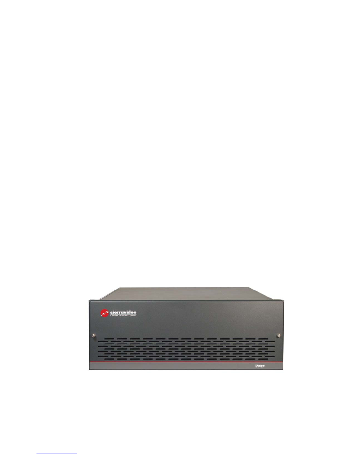
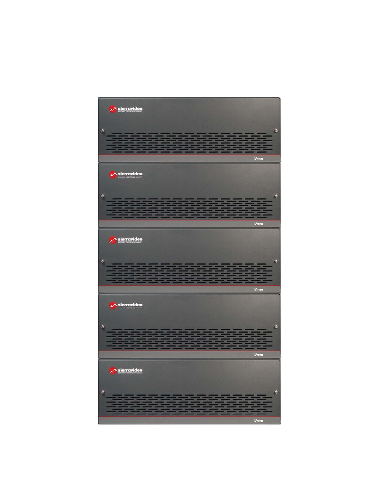
Viper RGBHV Frame
Frame Front Panels
6

Frame Rear Panels
VIPER COMPONENT SERIES
RED
GREEN
BLUE
H/HV SYNC
V SYNC
Note
The Viper models shown here and in the
subsequent sections are fully populated video
matrices. In some cases, the system may be
configured with fewer video channels and/or
frames. i.e. Viper models also offer redundant
power supplies. Consult the rear panel serial
number and model number to verify your order
and product.
The system you receive is customized for the size
& type requested at time of purchase from Sierra
Video.
7

SIERRA VIDEO
Factors Affecting Quality of Results
There are many factors affecting the quality of results when signals are transmitted from a source to a
destination.
Signal cables — Use only the best quality cables to avoid interference, degraded
signal quality and elevated noise levels.
Sockets and connectors of the sources and destinations — Use only the highest
quality, since "zero ohm" connection resistance is the target. Connectors should
also match the required impedance (75 ohm in video) to minimize return loss.
Amplifying circuitry — Must have quality performance when the desired end
result is high linearity, low distortion, and low noise.
Distance between sources and destinations — Plays a major role in the final
result. For long distances (over 15 meters) between sources and destinations,
special measures should be taken to avoid high frequency cable losses. These
measures include using higher quality cables and/or adding line cable equalizing
amplifiers.
Interference from neighboring electrical appliances — These can have an
adverse affect on signal quality. Balanced audio lines are less prone to
interference, but unbalanced audio should be installed away from any main
power lines, electric motors, transmitters, etc. even when the cables are shielded.
CAUTION!
Only an authorized Sierra Video technician can service the switchers. Any user who makes
changes or modifications to the unit without the expressed approval of the manufacturer will void
the warranty.
Use the proper AC voltage to supply power to the switcher.
Use only the recommended interconnect cables to connect the switcher to other frames
8

SIERRA VIDEO
Installation
Introduction
Installation procedures are similar for all frames covered within this manual. Exceptions, if any,
have been noted in each of the following paragraphs.
Rack Mounting
Chapter
2
Carefully inspect the frame to ensure that there has been no shipping damage. Make sure all
shipping material is removed from the router frame.
Each of the routing switchers described in this manual can be rack mounted in a standard 19"
(1RU) EIA rack assembly and includes rack "ears" at the ends of the front of the frames. None of
the switcher models require spacing above or below the unit for ventilation. To rack mount any of
the routing switchers, simply place the unit's rack ears against the rack rails of the rack, and
insert proper rack screws through each of the holes in the rack ears. Always rack mount the
routing switcher prior to plugging the unit into a power receptacle or attaching any cables.
Important; Rear mounting brackets must be installed prior to installation of the router into a
rack. The rear mounting brackets are contained in the accessory kit supplied with your router.
CAUTION!
The operating temperature range of the Viper series router is 0 to 40 °C. Do not exceed the maximum (40
°C) or minimum (0 °C) operating temperature.
Rear mounting brackets must be installed prior to installation of the router into a rack. The rear mounting
brackets are contained in the accessory kit supplied with your router.
If installed in a closed or multi-unit rack assembly, the operating ambient temperature of the rack
environment may be greater than the room ambient temperature. Therefore, consideration should be
given to installing the equipment in an environment compatible with the manufacturer’s maximum rated
ambient temperature (TMRA).
Installation of the equipment in a rack should be such that the amount of air flow required for safe
operation of the equipment is not compromised.
9
SIERRA VIDEO
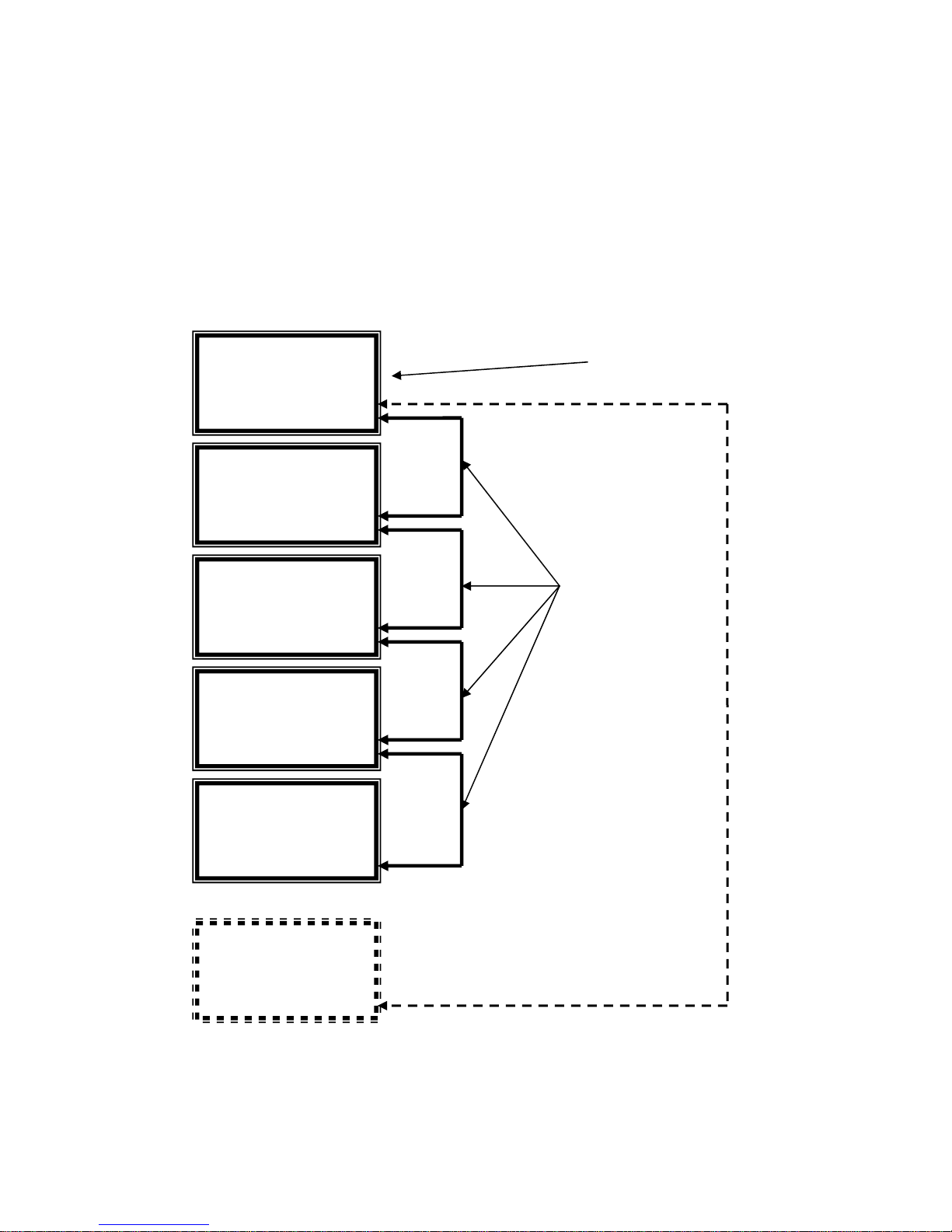
Multi-Frame Connections
The Viper RGBHV system consists of 5 individual frames connected together so that all 5 frames
operate as a single routing system. The “RED” frame contains the “Master” processor whereas
the other 4 frames each contain a “Slave” processor. The action of the slave frames are
controlled exclusively by the frame with the master processor. The frames are connected via a
“looping” 9-pin cable connected to the “multi-drop 1” port on each frame. The 25 pin J1 connector
is used when the audio option is ordered.
Control panels and serial control connect to the frame containing the master processor.
Master Frame
“RED”
Level 1
Multi Drop 1
Slave Frame
“GREEN”
Level 2
Multi Drop 1
Multi Drop 2
Slave Frame
“BLUE”
Level 3
Multi Drop 1
Multi Drop 2
Slave Frame
“H/HV SYNC”
Level 4
Multi Drop 1
Multi Drop 2
Control Panels, RS-232/422 Serial
Control and Ethernet control Connect to
This Frame
J1
9 Pin Multi-Frame
Interconnect Cables
Slave Frame
“V SYNC”
Level 5
Multi Drop 1
Optional Audio
Frame(s)
10
J1
See the “Connecting Peripherals”
section of this manual for details.

Connecting To Video Devices
Video sources and output devices (such as monitors, or recorders) may be connected to the
routing switchers through the BNC type connectors located on the back of the unit. Keep in mind
that the output signal format will be that of the input signal format.
All signal connections that use more than one cable interconnecting between devices should be
of equal timing length (example: cables between a camera and the switcher should have the
same time delay).
The rear panel of the frame is laid out in the most logical fashion possible. The individual frames
are RED, GREEN, BLUE, H/HV SYNC, and V SYNC. The H/HV and V conventions, used for the
H and V sync channels, are arbitrary and these two channels are interchangeable. Each channel
can have only “H” or “V” signals – not both. All inputs are factory set for 75 ohm termination.
Unused outputs do not need to be terminated.
Sync
Horizontal (“H”) and Vertical (“V”) sync input termination is factory set to 75 ohms. Sync input
terminations can be changed to 510 ohms.
VIPER COMPONENT SERIES
To change sync input terminations;
1. Connect the COMM port from a computer to “CTRL 1” on the back of the “Master” frame.
2. Open HyperTerminal, Hyper Access or other similar terminal emulation program.
3. Set the program’s parameters to 115.2K baud, 8 Data bits, No parity, 1 stop bit, ANSI emulation.
4. Establish communication to the router’s processor by typing **!! on the keyboard. The terminal
program screen will answer **OK!! confirming communication.
Note:
To change sync input termination the “CTRL 1” port must be in the “Host” protocol mode. “CTRL 1” is
factory default to the “Host” mode. However, the CTRL 1 port can be changed to “terminal” via software or
DIP switch. To change the CTRL 1 port to “Host” mode type **HOST1!! (see the operation chapter section
of this manual).
11

SIERRA VIDEO
To set sync input terminations, type in the command(s) below for the type of change you want to
make;
Note:
Global change (all sync boards, all sync levels, all sync inputs) to input termination of 75 ohm;
**G XFER_ASCII,253,0,0,0F10FF52~!!
**G XFER_ASCII,253,0,0,0F10FF730401FF~!!
Global change to sync input termination of 510 ohm;
**G XFER_ASCII,253,0,0,0F10FF52~!!
**G XFER_ASCII,253,0,0,0F10FF73040100~!!
Per Board- Per Level All inputs, termination of 75 ohm;
**G XFER_ASCII,253,0,0,0F10FF52~!!
**G XFER_ASCII,253,0,0,(Level)10(Board Address)730401FF~!!
Per Board- Per Level, sync input termination to 510 ohm;
**G XFER_ASCII,253,0,0,0F10FF52~!!
**G XFER_ASCII,253,0,0,(Level)10(Board Address)73040100~!!
Board inputs are in groups of eight.
Level Numbers;
Level 1= 0
Level 2= 1
Level 3= 2
Level 4= 3
Level 5= 4
12
V
Connecting Peripherals
Control panels, sync inputs, and power are all connected to the rear of the “Master” frame. The
peripherals area may vary depending on the model size and type.
VIPER COMPONENT SERIES
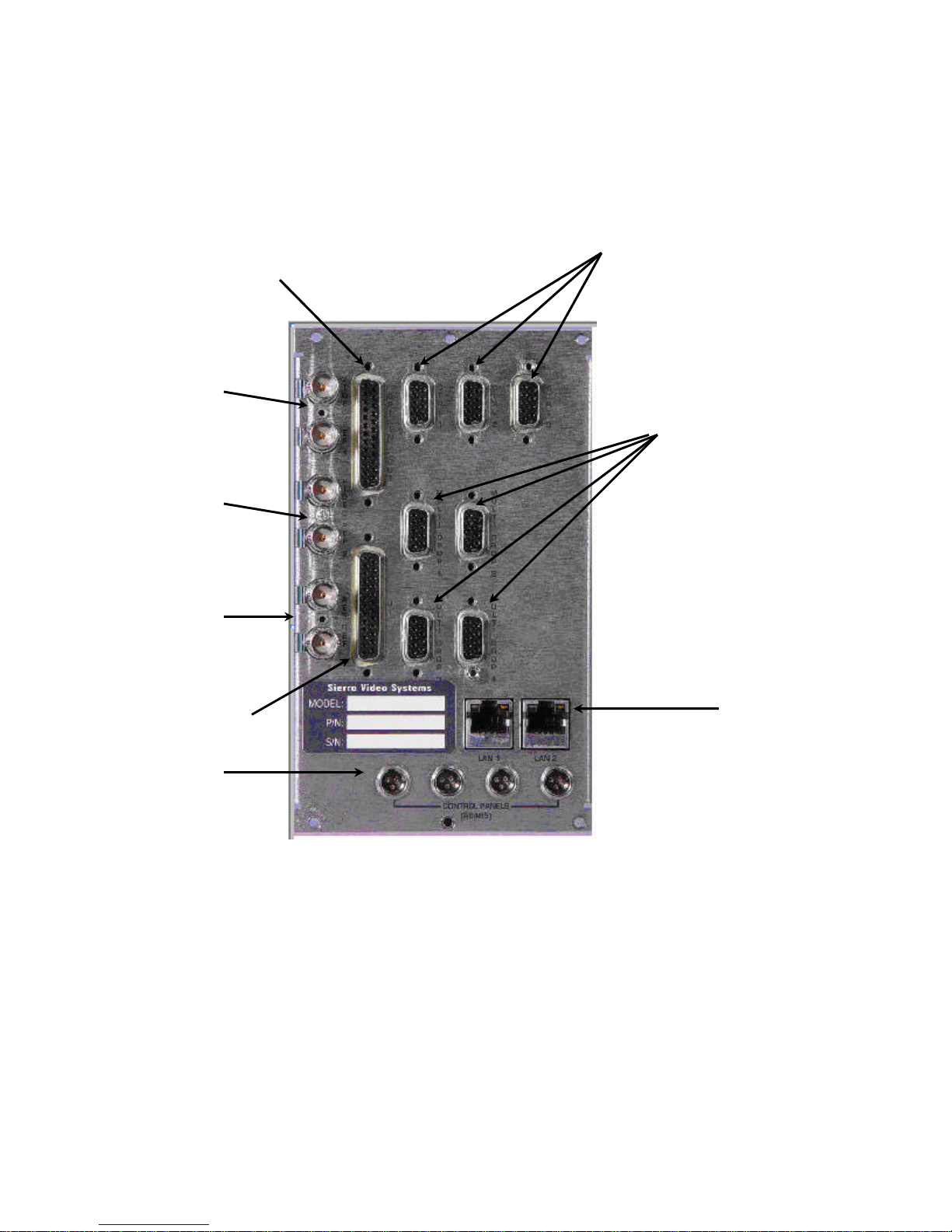
Master Frame Rear Panel
ideo Sync
Referencing
Inputs
(Looping)
Not Used
Not Used
GPI/0
RS-232 and RS-422
control connectors
Multi-Frame Inter
Connect
J1 Connector
Control Panel
Connectors
Ethernet
Connectors
13
SIERRA VIDEO
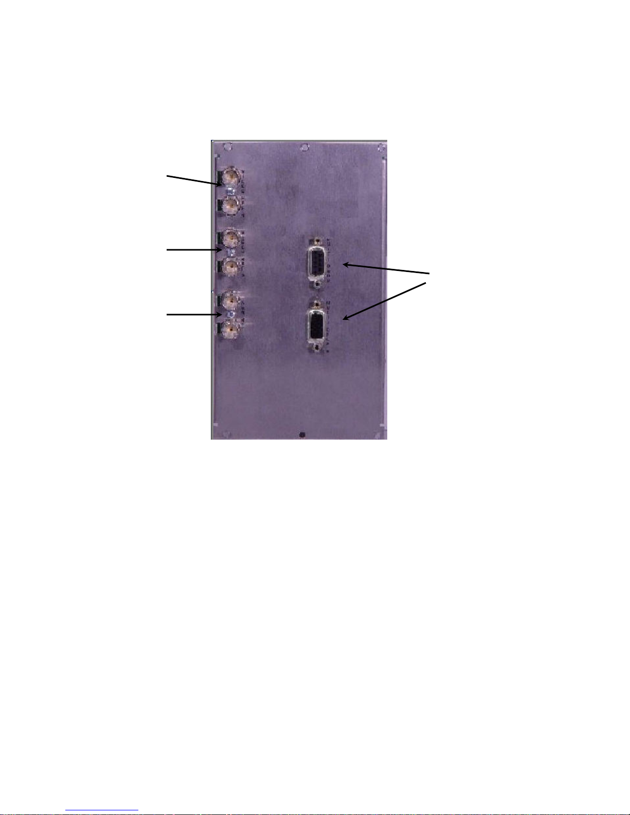
V
Slave Frame Rear Panel
Reference sync need not be connected unless the “Slave” frame contains a different signal type
than the “Master” frame, i.e. the master frame has video (which requires video sync) and the
slave frame has AES audio (which requires AES sync).
ideo Sync
Referencing
Inputs
Looping
Not Used
Not Used
Multi-Frame
Inter- Connect
14

VIPER COMPONENT SERIES
Reference Sync
There are three “looped” sets of BNC connectors labeled "VIDEO REF 1", “VIDEO REF 2””.
These are "looping" inputs for sync referencing. Connect either composite sync or video with sync
to either set of BNCs. If desired, use the second BNC in the set to loop the signal to another
device. If the loop is not used, terminate the second BNC with 75 ohms.
The set of sync connectors labeled “VIDEO REF 2” is for future use and are not
connected.
If no sync is available, the routing switcher will switch at a random point rather than during the
vertical interval of the reference signal.
Note:
Reference sync need only be connected to the “Master” frame. The “Master” frame is the frame where the
processor is installed, typically the “RED” frame.
15
SIERRA VIDEO
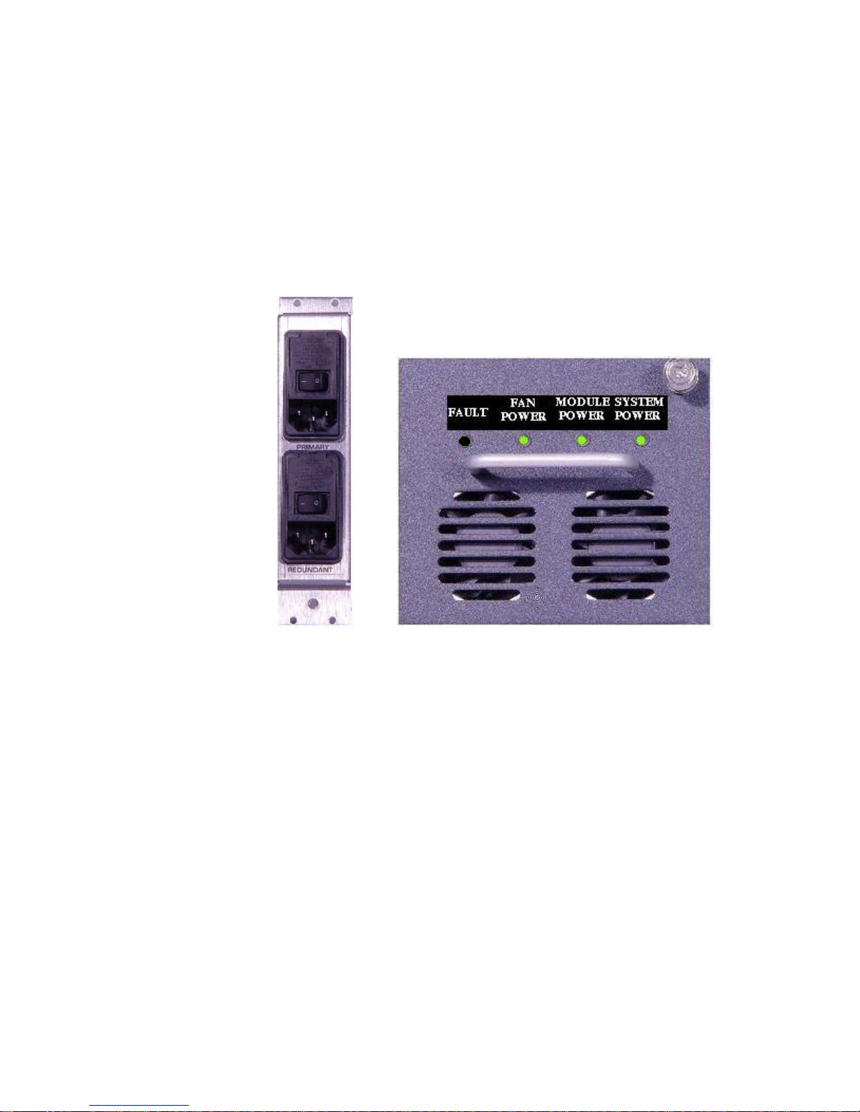
AC Power Connections
Viper series routing switchers offer redundant power supplies but must be specified prior to order.
The power supplies are universal AC inputs. Voltage selection is not necessary because the
power supply senses the correct AC input automatically.
The rear of the frame has two AC connectors labeled Primary and Redundant regardless of if
redundant power supplies are installed. For non-redundant power systems only the AC connector
“primary” is connected.
There are 4 “health monitoring” LEDs on each power supply. The LEDs indicate fan and power
status.
If redundant power supplies are ordered, the frame will contain two complete power supplies with
health monitoring LEDs. If a power supply should fail the other power supply will automatically
take over.
If a non-redundant power supply system is ordered, the redundant power supply slot will contain
a power supply frame with only the fan and health monitoring LEDs. This is referred to as a “fan
sled”. The “Module power” LED will not be lit on the fan sled. The redundant power AC
connection need not be connected for units with non-redundant power supplies. The fan sled will
operate from the primary power supply.
The “Fault” LED (red) turns on if there is a fan failure.
16
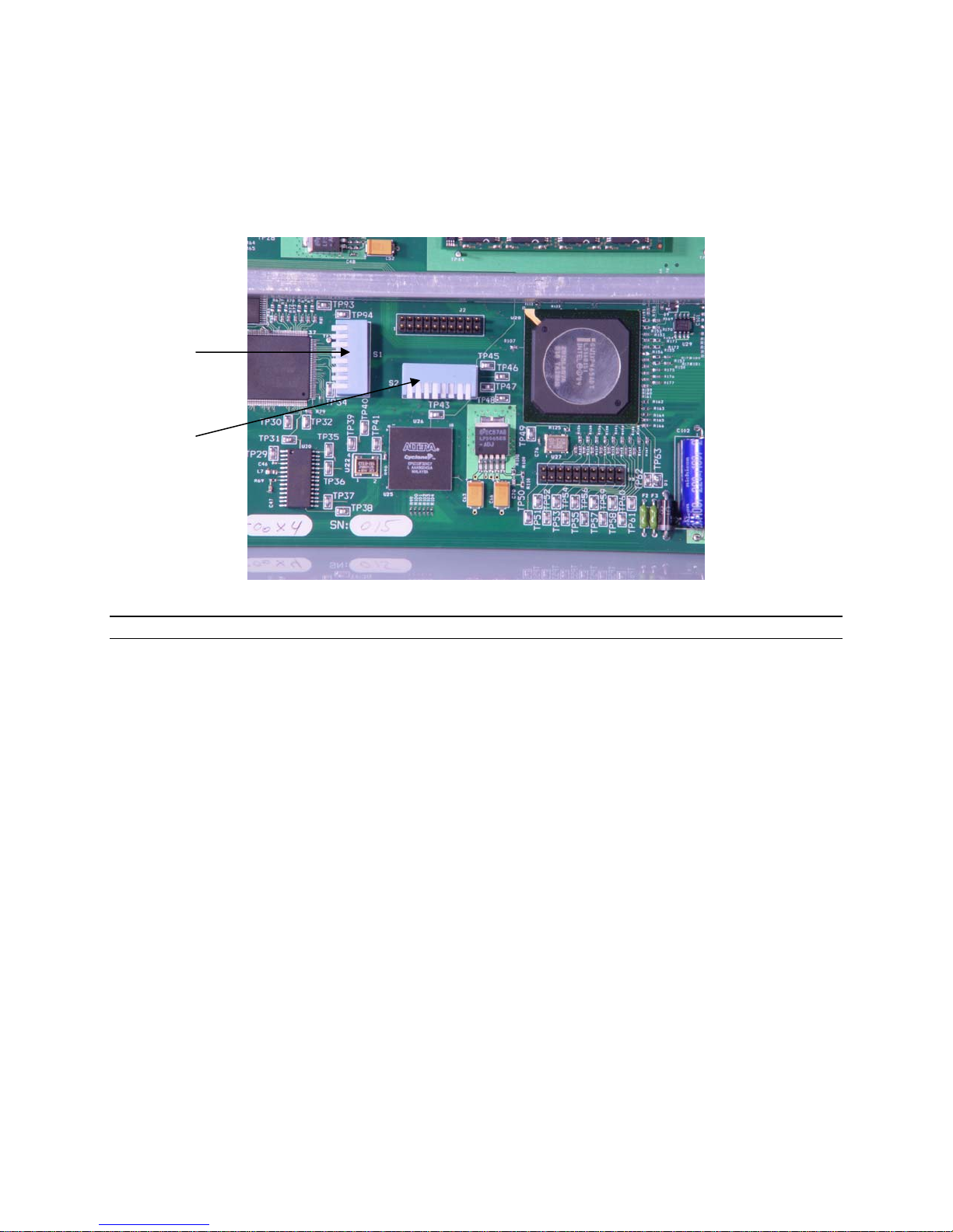
Control Processor DIP Switches
Your switcher has been configured at the factory for the settings you are most likely to need.
However, if you want to configure the switcher differently, you can do so by setting the switches
located on the processor board. DIP Switches and their action are given in the table that follows.
DIP Switches are shown in their factory default settings.
S1
S2
VIPER COMPONENT SERIES
Note:
Changing any DIP Switch causes an automatic reset after a few seconds.
Switch position down = ON.
17

SIERRA VIDEO
DIP Switch Settings Cont.
DIP Switch
1
2
3
4
5
6
7
8
S1 S2
Debug Messages
ON= Debug Messages
*OFF= Normal Operation
Bootloader Menu
ON= Menu Enable
*OFF= Menu Disable
Router Application Startup
ON= Application Disable
*OFF= Application Enable
Debug Server
ON= Server Enable
*OFF= Server Disable
Debug Break
ON= Break
*OFF= No Break
Unused- Set to OFF
Redundant Processor Enable
ON= Redundant Processors
OFF= Only One Processor
Preferred CPU Select
ON= Master CPU
OFF= Standby CPU
* = Factory Default Settings
Action
Force Crosspoint Initialization
ON= Set X-points to 1-1, 2-2, 3-3, etc.
*OFF= Last X-point Remembered
Initialize Non-Volatile Memory
ON= Clear All Settings
*OFF= Normal Operation
Port 1 Protocol
ON= Terminal Protocol- XOn/ XOff Enabled
*OFF= Port Can be Changed by Software
Port 1 Type
If S2-3 is ON;
ON= RS-422
*OFF= RS-232
If S2-3 is OFF Settings Can be Changed by Software
Port 1 Baud Rate
If S2-3 is ON;
1.2K Baud 5 = OFF, 6 = OFF
9.6K Baud 5 = OFF, 6 = ON
38.4K Baud 5 = ON, 6 = OFF
*115.2K Baud 5 = ON, 6 = ON
Unused
Unused
Note:
To manually set Port 1 to RS-422, turn S2-3 ON and S2-4 ON.
(Baud Rate is now set by S2-5 and S2-6)
18

VIPER COMPONENT SERIES
Ethernet Setup
There are two Ethernet connectors on the “Master” frame labeled “LAN 1” and “LAN 2”. For
single processor systems only “LAN 1” is active.
Ethernet connections are made to the connector labeled LAN 1.
Default IP settings;
IP Address- 192.168.1.200
***If there are redundant processors, the redundant processor IP
address will be 192.168.1.201 (LAN 2 connection)
Subnet mask- 255.255.255.0
Gateway IP Address- 0.0.0.0
Telnet Port- 10001
To set IP parameters using the Ethernet port;
1. Connect the Ethernet cable to “LAN 1” on the back of the “Master” frame.
2. Open the command prompt on a PC. In Windows XP Pro, you can access the Command Prompt
by clicking on the “Start” menu “Programs”, “Accessories”, “Command Prompt”.
3. Verify communications to the router by “Pinging” the router. You can do this by typing in the ping
command in the Command Prompt window as follows;
“ping 192.168.1.200” followed by a carriage return.
4. Once communications have been established you can Telnet into the router. You can do this by
typing in the telnet command in the Command Prompt window as follows;
“telnet 192.168.1.200” followed by a carriage return.
5. To login to the router, type “svsadmin” at the login prompt followed by a carriage return. Then
enter the password “TED” the password is case sensitive and must be typed in uppercase
characters.
6. To view the current network parameters you need to type in the following command;
“SvsBootApp Params” followed by a carriage return.
7. To change the IP address the command is as follows;
“SvsBootApp SetParam IP xxx.xxx.x.xxx
Where the “x” is the IP address you want to assign to the router.
8. To set the Subnet Mask the command is as follows;
“SvsBootApp SetParam SUBNET xxx.xxx.xxx.x
Where the “x” is the Subnet address you wish to assign to the router
9. Once the IP address and Subnet mask have been set you can close the telnet connection to the
router by typing “exit” at the \> prompt then restart the router by power cycling the “Master” frame.
10. Once the system has restarted you can verify that your settings are correct by pinging the IP
address you just assigned the router i.e.
“ping (your new IP address) followed by a carriage return.
Note:
192.168.1.200 is the factory default IP address. 192.168.1.201 is the address of the redundant processor
(if installed)
19

SIERRA VIDEO
To set IP parameters using the serial port;
1. Connect the COMM port from a computer to “CTRL 2” on the back of the “Master” frame.
2. Open HyperTerminal, Hyper Access or other similar terminal emulation program.
3. Set the program’s parameters to 115.2K baud, 8 Data bits, No parity, 1 stop bit, ANSI emulation.
4. Establish communication to the router’s processor by pressing the “Esc” button on the keyboard.
The terminal program screen will re-write confirming communication.
5. Turn the power off to the “Master” frame, leaving the terminal program running.
6. Remove the CPU board and set DIP switches S1-1 and S1-2, on the processor module, to on.
7. Replace the CPU board.
8. Turn power to the “Master” frame on.
9. The processor will begin to boot.
10. Within the first 4 seconds of boot-up when the processor is turned on, press the keyboard
spacebar. This will interrupt the booting of the unit and enter the configuration menu.
11. Press “0” and enter the IP information, then press ENTER.
12. Turn the “Master” frame off, remove the CPU and set the DIP switches S-1 and S1-2 back to the
off position.
13. Replace the board and power the frame up.
Note:
The Ethernet port accepts HOST protocol commands to switch the router. See the
section of this manual on Protocol for information on Host protocol commands.
*If your server is capable of IP reservations by the MAC address you can enable the DHCP option. It is
advisable to contact the Factory for further information regarding this feature.
Commands:
“SvsBootApp SetParam DHCP 0 “ DHCP disabled
“SvsBootApp SetParam DHCP 1” DHCP enabled
20

V18 and newer software
Software version 18 and newer contains web pages for switching the router. Once your PC and
the routing switcher are on the same Ethernet network, open your internet browser and type in
the default address of the routing switcher in the address line of the internet browser (factory
default 192.168.1.200). The following will display allowing switching of the router;
VIPER COMPONENT SERIES
You are provided with 3 different options to switch the router;
21