


Pro XL 8

SIERRA VIDEO
Pro XL Series 8 and Series 12 Routing Switchers
Models: 84V5S, 84V5, 88V5S, 88V5, 1204V5S, 1204V5,
1208V5S, 1208V5, 84V4S, 84V4, 88V4S, 88V4, 1204V4S,
1204V4, 1208V4S, 1208V4, 84V3S, 84V3, 88V3S, 88V3,
1204V3S, 1204V3, 1208V3S, 1208V3, 84V2S, 84V2, 88V2S,
88V2, 1204V2S, 1204V2, 1208V2S, 1208V2
User’s Manual


SIERRA VIDEO
SIERRA PRO XL FAMILY 8 AND 12 ROUTING SWITCHERS
User’s Manual
Sierra Video
P.O. Box 2462 Grass Valley, CA 95945
Tel: (530) 478-1000
Fax: (530) 478-1105
Email: info@sierravideo.com
Version 6.0
Publication Date: February 2012
The information contained in this manual is subject to change by Sierra Video


SIERRA VIDEO
Table of
Contents
Introduction 1
Before You Begin 1
Regulatory Warnings & Safety Information 2
FCC Notice 3
Warning 3
CE Notice 4
Warning 4
ICAN Class A Digital Equipment 4
Power Supply Cords 6
EMC Regulatory Notices 6
Delivery Damage Inspection 7
Sierra PRO XL Family Overview 8
Introduction 8
Model Suffix Designations 9
Sierra PRO System Components 9
Model 1208V5S 10
Model 88V5S 11
Factors Affecting Quality of Results 12
Operation 25
Introduction 25
Local Control Panel Operation 25
Switcher Operation 26
Button and Display Definitions 26
Menu 26
Switching the Router 29
Status 30
Control via 9-pin Connectors 31
Control via Ethernet 31
Host Mode 32
Terminal Mode 32
Power Up 32
Communication Protocol 33
Introduction 33
Generic Protocol 34
Commonly Used Switching Commands 58
Installation 13
Introduction 13
Rack Mounting 13
Dimensions 14
Connecting To Video Devices 15
Connecting To Audio Devices 15
Connecting Peripherals 17
Sync Input 18
AC Power Connections 18
Control Processor Dip Switch Settings 18
Ethernet Setup 19
Ethernet Control 21
Names 23
Room Grouping 23
Matrix Mapping 23
Sync Rate Reporting 24
Troubleshooting 59
Introduction 59
Power and Indicators 59
Video Signal 60
Audio Signal 61
Control 61
Switching Malfunctions 62
Software Upgrades 62
Specifications 63
Warranty 65
Contents - 1


SIERRA VIDEO
Introduction
Before You Begin
There are several terms and acronyms that you should become familiar with before reading this
manual. They are shown below.
Chapter
1
Term/Acronym Definition
Crosspoint The electronic switch that assigns one of the inputs to an
output.
Destination The output of a routing switcher connected to a device that
receives signals from the output of the switcher.
Output Connects the signal to the destination device.
Source The signal that is connected to the input of the routing
switcher.
Input Connected to the source that provides the signal to the
switcher.
Matrix An array of the switch modules that connects an input to an
output.
Protocol The command structure used to affect a switch or multiple
switches on the routing switcher or to control other
functions.
Routing Switcher Consists of one or more crosspoint modules that switch
together, or sometimes independently, to connect the
desired signals through the switcher.
Serial Port The 9-pin RS232 connector that allow you to control the
switcher using a standard personal computer or other
external device.
1

SIERRA VIDEO
Regulator y Warnings & Safety Information
The information in the following section provides important warnings and safety guidelines for
both the operator and service personnel. Specific warnings and cautions may be found
throughout this manual. Please read and follow the important safety precautions noting especially
those instructions relating to risk of fire, electrical shock and injury to persons.
Any instructions in this manual that require opening the equipment cover or enclosure are
intended for use by qualified service personnel only. To reduce the risk of electrical shock, do not
perform any servicing other than what is contained in the operating instructions unless you are
qualified.
Warnings
Heed all warnings on the unit and in the operating instructions.
Disconnect AC power before installing or removing device or servicing unit.
Do not use this product in or near water.
This product is grounded through the grounding conductor of the power cord. To
avoid electrical shock, plug the power cord into a properly wired receptacle before
connecting inputs or outputs.
Cautions
Route power cords and other cables so that they are not likely to be damaged, or
create a hazard.
Dangerous voltages exist at several points in this product. To avoid personal injury,
do not touch unsafe connections and components when th e power is on.
To avoid fire hazard, use only the specified type, correct voltage, and current rating
of fuse. Always refer fuse replacement to qualified service personnel.
Have qualified personnel perform safety checks after any comp leted service.
To reduce risk of electrical shock, be certain to plug each power supply cord into a
separate branch circuit employing a separate service ground.
If equipped with redundant power, this unit has two power cords. To reduce the risk
of electrical shock, disconnect both power cords before servicing.
Operate only with covers and enclosure panels in place – Do Not operate this
product when covers or enclosure panels are removed.
This is an FCC class A product. In a domestic environment, this product may cause
radio interference, in which case the user may be required to take necessary
measures.
Use the proper AC voltage to supply power to the switcher. When installing
equipment, do not attach the power cord to building surfaces.
To prevent damage to equipment when replacing fuses, locate and correct trouble
that caused the fuse to blow before applying power.
2

REGULATORY WARNINGS & SAFETY INFORMATION
Cautions (continued)
Use only the recommended interconnect cables to connect the switcher to other
frames.
Follow static precautions at all times when handling the equipment.
Leave the side, top, and bottom of the frame clear for air convection cooling and to
allow room for cabling. Slot and openings in the frame are provided for ventilation
and should not be blocked.
Only an authorized Sierra Video technician should service the switchers. Any user
who makes changes or modifications to the unit without the expressed approval of
the Sierra Video will void the warranty.
If installed in a closed or multi-unit rack assembly, the operating ambient
temperature of the rack environment may be greater than the room ambient
temperature. Therefore, consideration should be given to installing the equipment in
an environment compatible with the manufacturer’s maximum rated ambient
temperature (TMRA).
Installation of the equipment in a rack should be such that the amount of air flow
required for safe operation of the equipment is not compromised.
Use a shielded data cable connection between the parallel data ports and peripherals
of this equipment.
Other connections between peripherals of this equipment may be made with low
voltage non-sheilded computer data cables.
Network connections may consist of non-sheilded CAT 5 cable.
Do not cover chassis ventilation slots or block enclosure openings.
FCC Notice
This equipment has been tested and found to comply with the limits for a Class A digital device, pursuant
to Part 15 of the FCC rules. These limits are designed to provide reasonable protection against harmful
interference when the equipment is operated in a commercial environment. This equipment generates,
uses, and can radiate radio frequency energy and, if not installed and used in accordance with the
instruction manual, may cause harmful interference to radio communications. Operation of this equipment
in a residential area is likely to cause harmful interference in which case the user will be required to
correct the interference at the expense of the user.
The user may find the following publication prepared by the Federal Communications Commission
helpful:
“How to Identify and Resolve Radio-TV Interference Problems” (Stock number 004-00000345-4).
Available exclusively from the Superintendent of Documents, Government Printing Office,
Washington, DC 20402 (telephone 202 512-1800).
Warning
Changes or modifications not expressly approved by the party responsible for compliance to Part 15 of
the FCC Rules could void the user’s authority to operate the equipment.
3

SIERRA VIDEO
CE Notice
INFORMATION FOR THE USER
This equipment has been tested and found to comply with the limits for Class A or Class 1 digital device,
pursuant to EN 550022 Rules. These limits are designed to provide reasonable protection against harmful
interference when the equipment is operated in a commercial environment. This equipment generates,
uses, and can radiate radio frequency energy and, if not installed and used in accordance with the
instruction manual, may cause harmful interference to radio communications. Operation of this equipment
in a residential area is likely to cause harmful interference in which case the user will be required to
correct the interference at the expense of the user.
The user may find the following publication prepared by the Federal Communications Commission
helpful:
“How to Identify and Resolve Radio-TV Interference Problems” (Stock number 004-000-00345-4).
Available exclusively from the Superintendent of Documents, Government Printing Office,
Washington, DC 20402 (telephone 202 512-1800).
Warning
Changes or modifications not expressly approved by the party responsible for compliance to EN 55022
Rules could void the user’s authority to operate the equipment.
ICAN Class A Digital Equipment
This Class A digital apparatus meets all requirements of the Canadian Interference-Causing Equipment
Regulations.
Cet apparel numérique de la classe A respecte toutes les exigencies due Réglement sur le materiel
brouiller du Canada.
4

REGULATORY WARNINGS & SAFETY INFORMATION
Pulver Laboratories Inc. and Sierra Video Systems Inc. hereby certify that the Series 8 and Series 12
Sierra Pro router is in compliance with VFG 523/1969, DIN 57871 / VDE 0871 / 09.84, and DIN 5785 Part
1 A2 / 10.90 (product standards) and is RFI suppressed.
The marketing and sale of this equipment in Germany has been reported to the German Postal service.
They have also been given the right to retest this equipment to verify compliance with product regulations.
Compliance with applicable regulations depends on the use of shielded cables. The user is responsible
for procuring the appropriate cables.
This equipment has been tested concerning compliance with the relevant RFI protection requirements
both individually and on a system level (to simulate normal operation conditions). However, it is possible
that these RFI requirements are not met under certain unfavorable conditions in other installations. The
user is responsible for compliance of his particular installation.
Pulver Laboratories Inc.
Testing and Certification Laboratories
Sierra Video Systems
Name of Manufacturer or Importer
Bescheinigung des Pulver Laboratories Inc. und Sierra Video Systems hiermit wird bescheinigt, dass die
Series 8 and Series 12 Sierra Pro router in Űbereinstimmung mit den Bestimmungen der VFG 523/1969,
DIN 57871 / VDE 0871 / 09.84, und DIN 57875 Part 1 A2 / 10.90 (Amtsblattvertugung) funk-entstőrt ist.
Der deutschen Bundespost wurde das Inverkehrbringen dieses Geräts angezeigt und die Berechtigungen
zur Űberprűfung der Serie auf Einhaltung der Bestimmungen eingeräumt.
Einhaltung mit betreffenden Bestimmungen kommt darauf an, dass geschirmte Ausfűhrungen gerbraucht
warden. Fűr die Beschaffung richtiger Ausfűhrungen ist der Betreiber Verantwortlich.
Dieses Gerät wurde sowohl einzeln als auch in einer Anlage, die einen normalen Anwendungsfall
nachbildet, auf die Einhaltung der Funk-entstőrbestimmungen unter Ungűnstigen Umständen bei anderen
Gerätekombinationen nicht Eingehalten warden. Der Betreiber ist fűr die Einhaltung der funkeutstőrungsbestimmungen seiner gesamten Anlage verantwortlich, in der dieses Gerät betrieben wird.
Pulver Laboratories Inc.
Testing and Certification Laboratories
Sierra Video Systems
Name des Herstellers / Importeurs
5

SIERRA VIDEO
Pow er Supply Cords
Use only power cord(s) supplied with the unit.
If power cord(s) were not supplied with the unit, select as follows:
For units installed in the USA and Canada: select a flexible, three-conductor power cord
that is UL listed and CSA certified, with individual conductor wire size of #18 AWG, and a
maximum length of 4.5 meters. The power cord terminations should be NEMA Type 515P (three-prong earthing) at one end and IEC appliance inlet coupler at the other end.
Any of the following types of power cords are acceptable; SV, SVE, SVO, SVT, SVTO,
SVTOO, S, SE, SO, SOO, ST, STO, STOO, SJ, SJE, SJO, SJOO, SJT, SJTOO, SP-3,
G, W.
For units installed in all other countries; select only a flexible, three-conductor power
cord, approved by the cognizant safety organization of your country. The power cord
must be Type HAR (Harmonized), with individual conductor wire size of 0.75 mm². The
power cord terminations should be a suitably rated earthing-type plug at one end and IEC
appliance inlet coupler at the other end. Both of the power cord terminations must carry
the certification label (mark) of the cognizant safety organization of your country.
A non-shielded power cord may be used to connect AC power to every component and
peripheral of the system.
Connect an external 16 AWG wire from earth ground to the chassis of the system as
designated by the earth ground symbol.
North American Power Supply Cords
This equipment is supplied with North American power cords with molded grounded plug (NEMA15P) at one end and molded grounding connector (IEC 320-C13) at the other end. Conductors
are CEE color coded, light blue(neutral), brown(line), and green/yellow(ground). Operation of the
equipment at voltages exceeding 130VAC will require power supply cords that comply with NEMA
configurations.
International Power Supply Cords
If shipped outside North America, this equipment is supplied with molded ground connector (IEC
320-C13) at one end and stripped connectors (50/5mm) at the other end. Connections are CEE
color coded, light blue (neutral), brown (line), and green/yellow (ground). Other IEC 320-C13 type
power cords can be used if they comply with safety regulations of the country in which they are
installed.
EMC Regulatory Notices
6
Federal Communications Commission (FCC) Part 15 Information: This device complies with Part
15 of the FCC standard rules. Operation is subject to the following conditions:
This device may not cause harmful interference.
This device must accept any interference received including interference that may cause
undesirable operations.

REGULATORY WARNINGS & SAFETY INFORMATION
Delivery Damage Inspection
Carefully inspect the frame and exterior components to be sure that there has been no shipping
damage. Make sure all modules are seated correctly and have not detached during shipment.
Also, make sure the input buffer modules on the rear panel are secure.
7
SIERRA VIDEO
Sierra PRO XL Family Overview
Introduction
The Sierra PRO XL Family of component analog routing switchers offers high-bandwidth 3, 4, or
5 channel (RGB + HV) and stereo audio (S) matrix routing capability in a series of compact
frames. Sierra PRO was designed specifically for presentation environments such as corporate
boardrooms, live staging events, churches, and
universities.
This manual covers only the 12x8, 12x4, 8x8, and 8x4
Sierra PRO routing switchers. These robust routers offer
RGB/HV and Stereo Audio in the same, compact frame.
Moreover, these durable frames can be populated from
one to five video and pulse sync channels. They have
been engineered for high bandwidth with very low
crosstalk. Many other features include audio gain
adjustment for Inputs and Outputs through standard front
control panels or via a control serial port and optional
redundancy. The Sierra PRO system accommodates
balanced or un-balanced audio, AFV, or breakaway split
routing allowing RGB muting for seamless performance to projectors and displays. This family of
SVS routing switchers is optimized for multiple signal type control within the same frame.
Composite, S-video, YC, YUV, RGBHV, analog HD, and audio are easily control with one small
Sierra PRO frame. Sierra PRO’s 450MHz bandwidth supports most high-resolution sources.
The Sierra PRO models also feature a user-friendly, color-coded (RGB) rear panel layout for easy
installation, and their own unique motherboard configuration options. Frames also come with
standard front local control panel, serial control via an RS-232/422 serial interface, and an RJ-45
Ethernet port, with up to five simultaneous users, that is supported by SVS software and by all
major third-party control systems. An extensive line of existing XY or single-bus remote control
panels is also available.
8
SIERRA PRO XL FAMILY OVERVIEW
Model Suffix Designations
Model Suffix Designations
V Analog video (450MHz bandwidth)
88, 84, 128, 124 Matrix size
# Number of video and sync channels (analog, YC, RGB, RGB+HV etc.)
S Stereo audio
R
Redundant Power Supplies
Sierra PRO System Components
This User's Manual provides installation and operation information for the Series 12 and Series 8
Routing Switchers. Front and Rear panel illustrations are provided in the following subsections for
each switcher model. Take time to familiarize yourself with the location of your switcher model
features
Component
Video Frame
1208V5S, 1208V5, 1208V4S,
1208V4, 1208V3S, 1208V3 & lower
1204V5S, 1204V5, 1204V4S,
1204V4, 1204V3S, 1204V3 & lower
Video and Audio contained in one
frame
Power Supply(ies)
Video Motherboard Board
Audio Motherboard Board
Local Control Panel
Sierra PRO Family 8 & 12 Switchers
88V5S, 88V5, 88V4S, 88V4,
88V3S, 88V3 & lower
84V5S, 84V5, 84V4S, 84V4,
84V3S, 84V3 & lower
Video and Audio contained
in one frame
Power Supply(ies)
Video Motherboard Board
Audio Motherboard Board
Local Control Panel
Accessory Kit User’s Manual
5-pin Audio Connectors
Fuses
Power Cord
Software Disk
9
User’s Manual
5-pin Audio Connectors
Fuses
Power Cord
Software Disk
SIERRA VIDEO
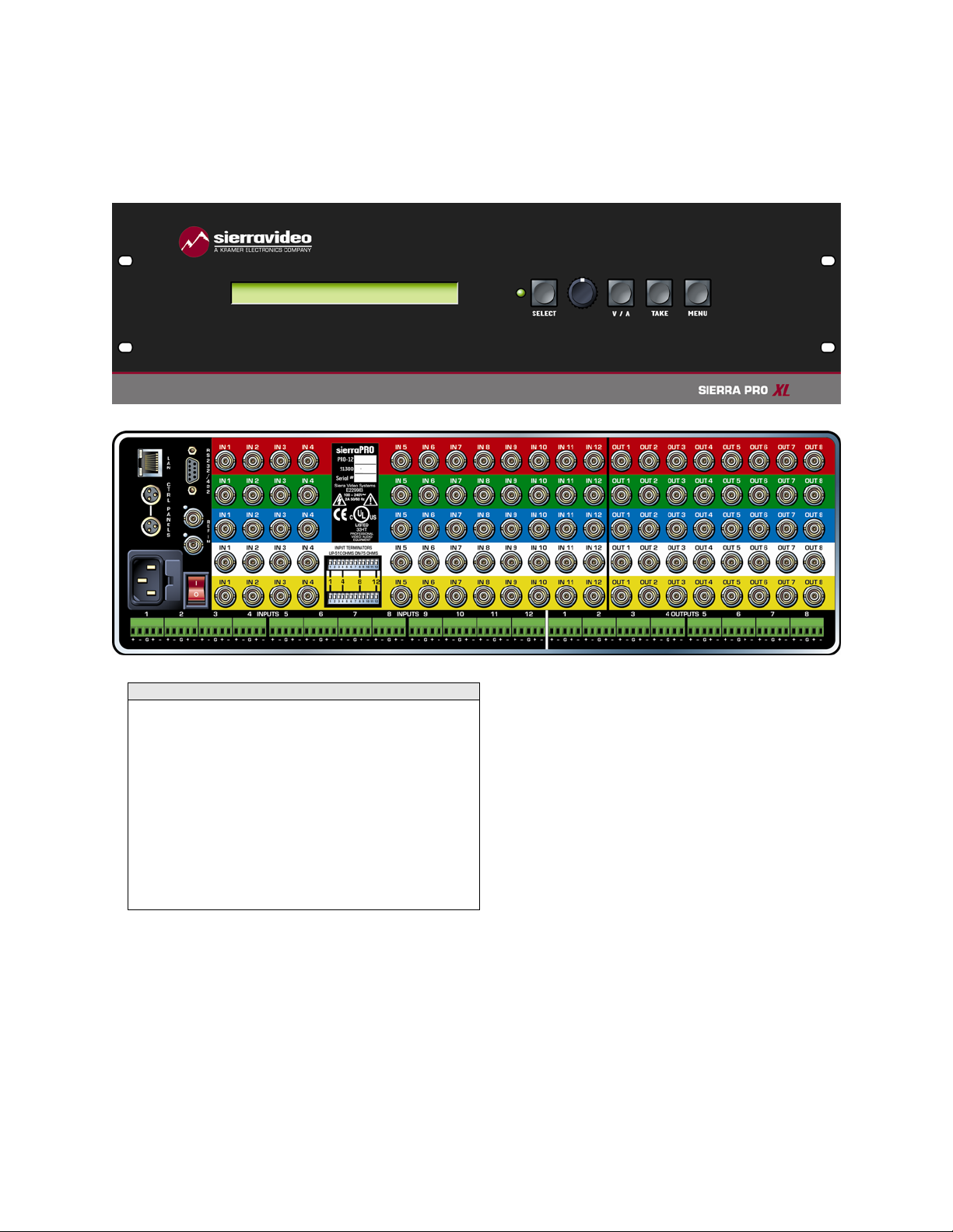
Model 1208V5S
Frame Front Panel
Video Frame Back Panel
Note
The Sierra PRO models shown here and in the
subsequent sections are fully populated video
and audio matrices. In some cases, these frames
may be configured with fewer video channels and
perhaps no audio i.e. 1208V3. Sierra PRO models
also offer redundant power supplies. Consult the
rear panel serial number and model number to
verify your order and product.
The system you receive is customized for the size
& type requested at time of purchase from Sierra
Video Systems.
10
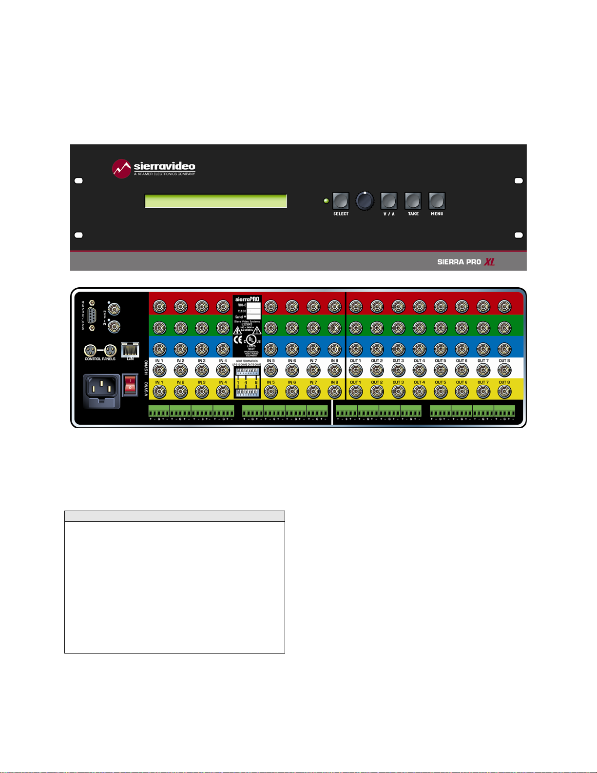
MODEL 88V5S
Model 88V5S
Frame Front Panel
Video Frame Back Panel
Note
The Sierra PRO models shown here and in the
subsequent sections are fully populated video
and audio matrices. In some cases, these frames
may be configured with fewer video channels and
perhaps no audio i.e. 1208V3. Sierra PRO models
also offer redundant power supplies. Consult the
rear panel serial number and model number to
verify your order and product.
The system you receive is customized for the size
& type requested at time of purchase from Sierra
Video Systems.
11

SIERRA VIDEO
Factors Affecting Quality of Results
There are many factors affecting the quality of results when signals are transmitted from a source
to a destination.
Signal cables — Use only the best quality cables to avoid interference and
degraded signal quality and elevated noise levels.
Sockets and connectors of the sources and destinations — Use only the highest
quality, since "zero ohm" connection resistance is the target. Connectors should
also match the required impedance (75 ohm in video) to minimize return loss.
Amplifying circuitry — Must have quality performance when the desired end
result is high linearity, low distortion, and low noise.
Distance between sources and destinations — Plays a major role in the final
result. For long distances (over 15 meters) between sources and destinations,
special measures should be taken to avoid high frequency cable losses. These
measures include using higher quality cables and/or adding line cable equalizing
amplifiers.
Interference from neighboring electrical appliances — These can have an
adverse affect on signal quality. Balanced audio lines are less prone to
interference, but unbalanced audio should be installed away from any main
power lines, electric motors, transmitters, etc. even when the cables are shielded.
CAUTION!
Only an authorized Sierra Video technician can service the switchers. Any user who makes
changes or modifications to the unit without the expressed approval of the manufacturer will void
the warranty
Use the proper AC voltage to supply power to the switcher.
Use only the recommended interconnect cables to connect the switcher to other frames.
12

SIERRA VIDEO
Installation
Introduction
Installation procedures are similar for all frames covered under this manual. Exceptions, if any,
have been noted in each of the following paragraphs.
Chapter
2
Rack Mounting
Carefully inspect the frame to ensure that there has been no shipping damage. Make sure all
shipping material is removed from the router frame.
Each of the routing switchers described in this manual can be rack mounted in a standard 19"
(RU) EIA rack assembly and includes rack "ears" at the ends of the front of the frames. None of
the switcher models require spacing above or below the unit for ventilation. If ample space exists,
a 1RU spacing gap is recommended.
To rack mount any of the routing switchers, simply place the unit's rack ears against the rack rails
of the rack, and insert proper rack screws through each of the holes in the rack ears. Always rack
mount the routing switcher prior to plugging the unit into a power receptacle or attaching any
cables.
CAUTION!
The operating temperature range of the SV 8 &12 series router is 0 to 40 °C. Do not exceed the
maximum (40 °C) or minimum (0 °C) operating temperature.
If installed in a closed or multi-unit rack assembly, the operating ambient temperature of the rack
environment may be greater than the room ambient temperature. Therefore, consideration should be
given to installing the equipment in an environment compatible with the manufacturer’s maximum rated
ambient temperature (TMRA).
Installation of the equipment in a rack should be such that the amount of air flow required for safe
operation of the equipment is not compromised.
13

SIERRA VIDEO
Dimensions
Series 8 and Series 12 frames are 3 rack units high, 19” wide, and 11” deep.
14
INSTALLATION
Connecting To Video Devices
Video sources and output devices (such as monitors, or recorders) may be connected to the
routing switchers through the BNC type connectors located on the back of the unit. Keep in mind
that the output signal format will be that of the input signal format.
All signal connections that use more than one cable interconnecting between devices should be
of equal timing length (example: cables between a camera and the switcher should have the
same time delay).
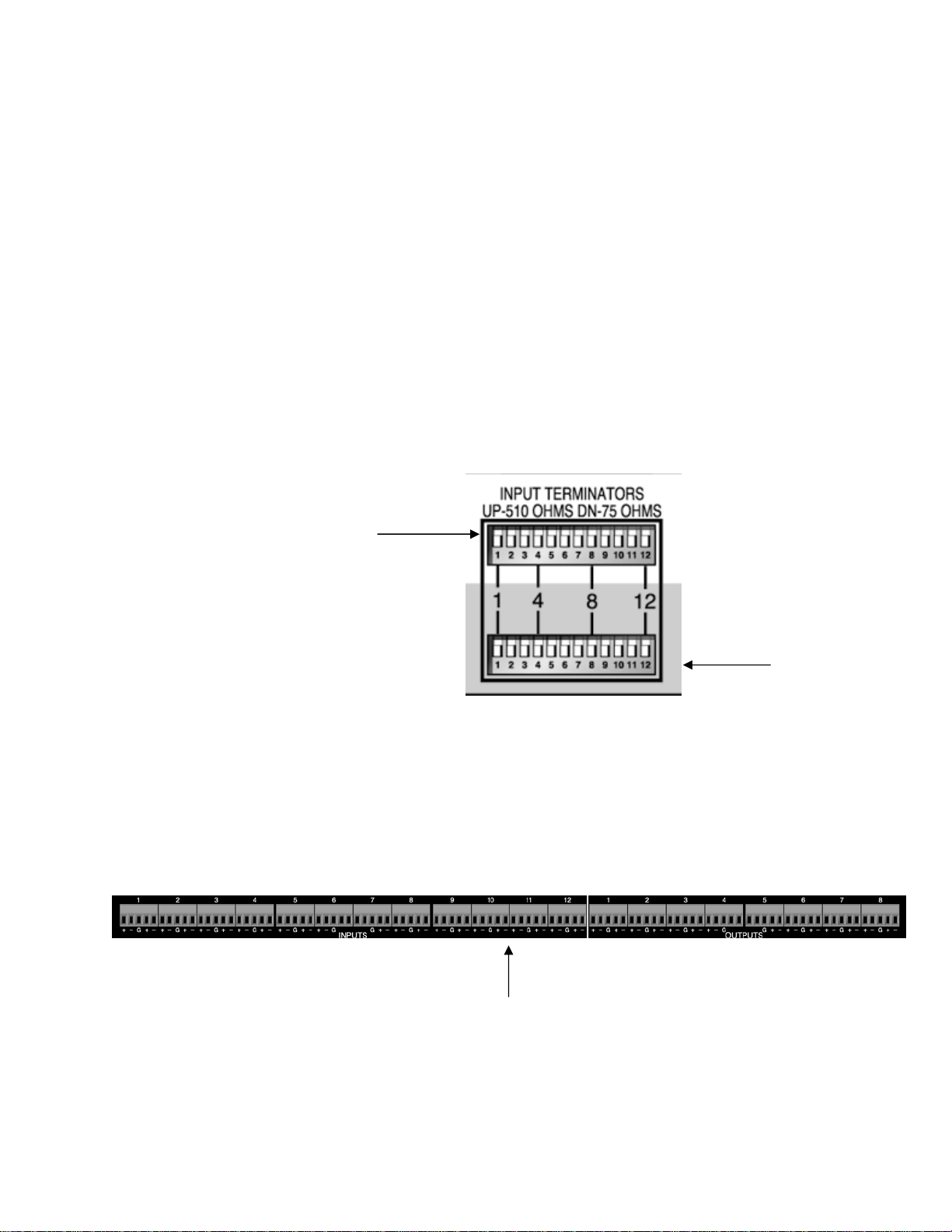
The rear panel of the frame is laid out in the most logical fashion possible. The individual
channels are color-coded. The white and yellow conventions, used for the H and V sync
channels, are arbitrary and these two channels are interchangeable. Each channel can have only
“H” or “V” signals – not both. All inputs are factory set for 510 ohm termination. The sync (“H” “V”)
input terminations can be changed to 75 ohm by changing the dip switches located on the rear
panel of the router. The upper row of switches applies to the “white” row of inputs with the lower
row of switches applying to the “yellow” row. Unused outputs do not need to be terminated.
Upper DIP
Switch
Rear panel DIP
Switches
Connecting To Audio Devices
Audio sources and output devices (such as amplifiers or recorders) are connected to the
switchers through the terminal block connectors located at, and marked, on the rear of the
switcher.
Lower DIP
Switch
15
SIERRA VIDEO
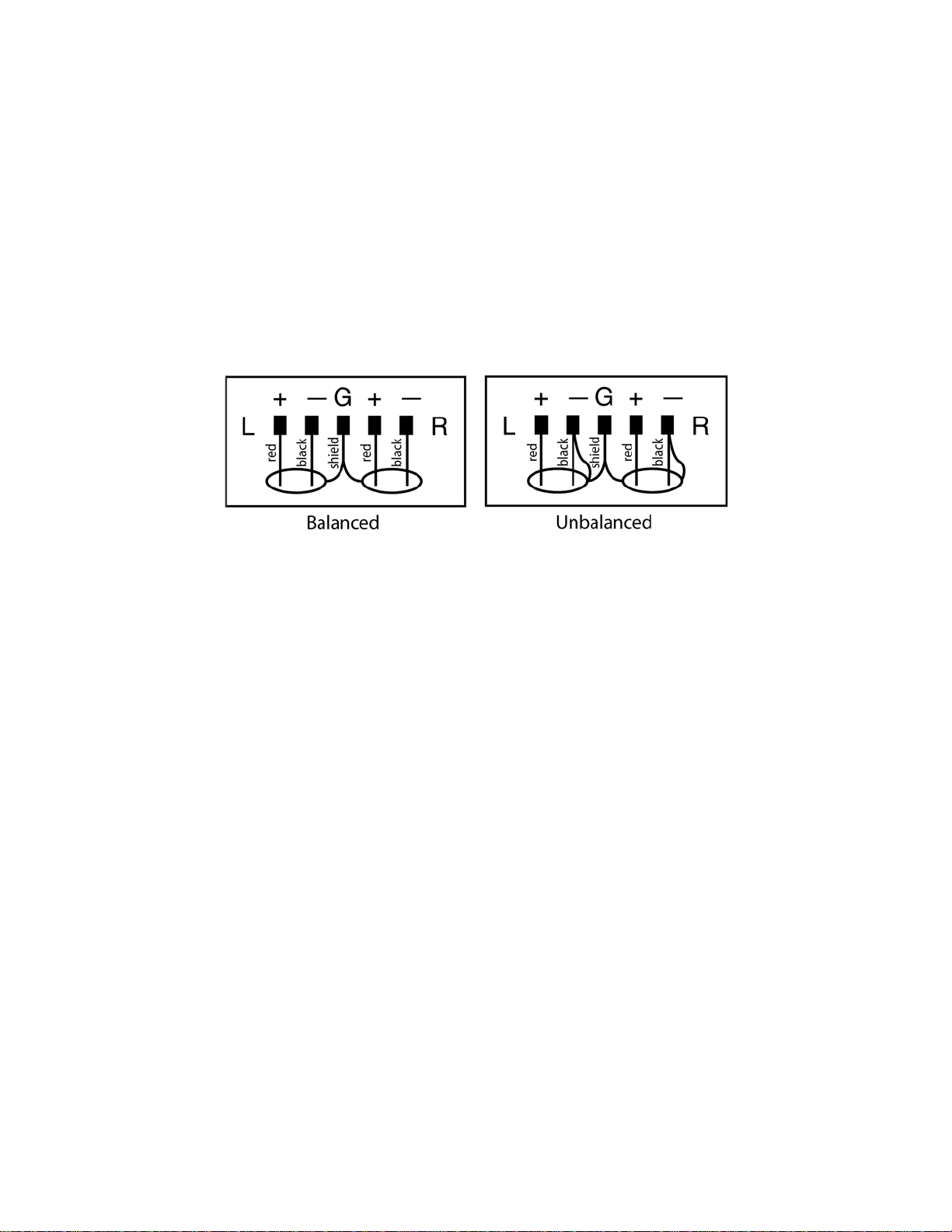
Balanced/Unbalanced Audio Connections
All audio sources from the routing switcher are balanced audio. Connect the balanced audio to
the balanced input of your destination device(s).
If this is a 2-channel system used for stereo audio, ensure that you keep the same phase
relationship. Connect the positive designated pin to the same relative pin on the destination
device of both channels.
To connect an unbalanced device to the switcher, first place a jumper between the negative (-)
and the ground on the switcher (jumper not included.) Then connect the device positive (+) to
positive (+) and shield to ground as shown in the graphic below.
For unbalanced sources, connect the unbalanced source to one side of the balanced input and
ground. The other input does not have to be grounded. Note, always use the same side of the
balanced input for stereo.
Audio Adjustments
Unity gain is set at the factory. Audio gain is adjusted via a menu option. See “Menu Items” in the
Operation section Chapter 3. Audio gains may also be adjusted via the 9 pin serial port using the
TyLinx Pro program (refer to the TyLinx Pro manual), or using Host protocol (see Communication
protocol Chapter 4).
Audio Follo w Video and Breakaway Audio Configurations
Component video (YC, RGB etc.) signals are switched by separate crosspoint modules. All
crosspoint modules will be switched at the same time. Audio can be switched following the video
or separately after the breakaway.
16
 Loading...