


SIERRA VIDEO
SVG Multi-Viewer
User’s Manual

S V G M U L T I - V I E W E R
User’s Manual
Sierra Video
P.O. Box 2462 Grass Valley, CA 95945
Tel: (530) 478-1000
Fax: (530) 478-1105 Email: info@sierravideo.com
Version 4.0
Publication Date: October 2013
The information contained in this manual is subject to change by Sierra Video
SIERRA VIDEO
Regulatory Warnings & Safety Information
The information in the following section provides important warnings and safety guidelines for both the operator and service personnel. Specific warnings and cautions may be found throughout this manual. Please read and follow the important safety precautions noting especially those instructions relating to risk of fire, electrical shock and injury to persons.
Any instructions in this manual that require opening the equipment cover or enclosure are intended for use by qualified service personnel only. To reduce the risk of electrical shock, do not perform any servicing other than what is contained in the operating instructions unless you are qualified.
 Warnings
Heed all warnings on the unit and in the operating instructions.
Disconnect AC power before installing or removing device or servicing unit.
Do not use this product in or near water.
This product is grounded through the grounding conductor of the power cord. To avoid electrical shock, plug the power cord into a properly wired receptacle before connecting inputs or outputs.
Route power cords and other cables so that they are not likely to be damaged, or create a hazard.
Dangerous voltages exist at several points in this product. To avoid personal injury, do not touch unsafe connections and components when the power is on.
Have qualified personnel perform safety checks after any completed service.
To reduce risk of electrical shock, be certain to plug each power supply cord into a separate branch circuit employing a separate service ground.
If equipped with redundant power, this unit has two power cords. To reduce the risk of electrical shock, disconnect both power cords before servicing.
Operate only with covers and enclosure panels in place – Do Not operate this product when covers or enclosure panels are removed.
This is an FCC class A product. In a domestic environment, this product may cause radio interference, in which case the user may be required to take necessary measures.

SVG MULTI-VIEWER
 Cautions
Use the proper AC voltage to supply power to the switcher. When installing equipment, do not attach the power cord to building surfaces.
Use only the recommended interconnect cables to connect the switcher to other frames.
Follow static precautions at all times when handling the equipment.
Power this product only as described in the installation section of this manual.
Leave the sides of the frame clear for air convection cooling and to allow room for cabling. Slot and openings in the frame are provided for ventilation and should not be blocked.
Only an authorized Sierra Video technician should service the switchers. Any user who makes changes or modifications to the unit without the expressed approval of Sierra Video will void the warranty.
If installed in a closed or multi-unit rack assembly, the operating ambient temperature of the rack environment may be greater than the room ambient temperature. Therefore, consideration should be given to installing the equipment in an environment compatible with the manufacturer’s maximum rated ambient temperature (TMRA).
Installation of the equipment in a rack should be such that the amount of air flow required for safe operation of the equipment is not compromised.
Other connections between peripherals of this equipment may be made with low voltage non-shielded computer data cables.
Network connections may consist of non-shielded CAT 5 cable.
Do not cover chassis ventilation slots or block enclosure openings.
FCC Notice
This equipment has been tested and found to comply with the limits for a Class A digital device, pursuant to Part 15 of the FCC rules. These limits are designed to provide reasonable protection against harmful interference when the equipment is operated in a commercial environment. This equipment generates, uses, and can radiate radio frequency energy and, if not installed and used in accordance with the instruction manual, may cause harmful interference to radio communications. Operation of this equipment in a residential area is likely to cause harmful interference in which case the user will be required to correct the interference at the expense of the user.
The user may find the following publication prepared by the Federal Communications Commission helpful:
“How to Identify and Resolve Radio-TV Interference Problems” (Stock number 004-000-00345-4). Available exclusively from the Superintendent of Documents, Government Printing Office,
Washington, DC 20402 (telephone 202 512-1800).
Warning
Changes or modifications not expressly approved by the party responsible for compliance to Part 15 of the FCC Rules could void the user’s authority to operate the equipment.
SIERRA VIDEO
Power Supply Cords
Use only power cord(s) supplied with the unit.
If power cord(s) were not supplied with the unit, select as follows:
For units installed in the USA and Canada: select a flexible, three-conductor power cord that is UL listed and CSA certified, with individual conductor wire size of #18 AWG, and a maximum length of 4.5 meters. The power cord terminations should be NEMA Type 5-15P (three-prong ground) at one end and IEC appliance inlet coupler at the other end. Any of the following types of power cords are acceptable; SV, SVE, SVO, SVT, SVTO, SVTOO, S, SE, SO, SOO, ST, STO, STOO, SJ, SJE, SJO, SJOO, SJT, SJTOO, SP-3, G, W.
For units installed in all other countries; select only a flexible, three-conductor power cord, approved by the cognizant safety organization of your country. The power cord must be Type HAR (Harmonized), with individual conductor wire size of 0.75 mm². The power cord terminations should be a suitably rated earthing-type plug at one end and IEC appliance inlet coupler at the other end. Both of the power cord terminations must carry the certification label (mark) of the cognizant safety organization of your country.
A non-shielded power cord may be used to connect AC power to every component and peripheral of the system.
Connect an external 16 AWG or larger wire from earth ground to the chassis of the system as designated by the earth ground symbol.
North American Power Supply Cords
This equipment is supplied with North American power cords with molded grounded plug (NEMA15P) at one end and molded grounding connector (IEC 320-C13) at the other end. Conductors are CEE color coded, light blue(neutral), brown(line), and green/yellow(ground). Operation of the equipment at voltages exceeding 130VAC will require power supply cords that comply with NEMA configurations.
International Power Supply Cords
If shipped outside North America, this equipment is supplied with molded ground connector (IEC 320-C13) at one end and stripped connectors (50/5mm) at the other end. Connections are CEE color coded, light blue (neutral), brown(line), and green/yellow(ground). Other IEC 320-C13 type power cords can be used if they comply with safety regulations of the country in which they are installed.
EMC Regulatory Notices
Federal Communications Commission (FCC) Part 15 Information: This device complies with Part 15 of the FCC standard rules. Operation is subject to the following conditions:
This device may not cause harmful interference
This device must accept any interference received including interference that may cause undesirable operations.
Delivery Damage Inspection
Carefully inspect the frame and exterior components to be sure that there has been no shipping damage.
SIERRA VIDEO
Table of
Contents
Regulatory Warnings & Safety Information |
1 |
FCC Notice |
2 |
Power Supply Cords |
3 |
EMC Regulatory Notices |
3 |
Delivery Damage Inspection |
3 |
Overview |
1 |
SVG Multi-Viewer |
1 |
Installation |
5 |
Introduction |
5 |
Dimensions |
5 |
Input/ Output Rear Panel |
7 |
Overview |
7 |
RS-232 Connection |
8 |
Timing Connection |
8 |
Single Output System |
9 |
Dual Output System |
10 |
Input Rear Panel |
11 |
SD/HD/3G Input module |
11 |
HDMI Input module |
12 |
CVBS/SDI Input module |
13 |
Output Rear Panel |
14 |
HDMI/VGA Output Card |
14 |
HDMI/HD/SDI Output Card |
16 |
Typical Application |
17 |
Configuration |
19 |
Using the Web-Server |
19 |
Basic Physical Configuration |
20 |
Edit Input Source |
21 |
Edit Screens |
23 |
General Configuration |
24 |
System Settings |
25 |
Create a Channel |
26 |
Create a Video Channel |
27 |
Choose an Input Source |
29 |
Video Channel input Source (HD) |
30 |
Make/Delete signal marker |
31 |
Create Clock/ Timer/ Logo |
33 |
Delete an Object |
34 |
Clear All |
34 |
|
|
|
Screen 1 and Screen 2 |
35 |
|
Quick Tools |
36 |
|
Alignment Tools |
37 |
|
Layout Management |
38 |
|
Download Layout File |
39 |
|
Upload Layout File |
39 |
|
HDMI/VGA Output Resolution |
39 |
|
SDI Output Resolution HDSDI/HDMI Output |
||
Card |
40 |
|
Audio Monitor Output Select |
41 |
|
Frame Layout |
43 |
|
Aspect Ratio |
43 |
|
Input Source |
43 |
|
Waveform Display |
44 |
|
UMD and Audio Meters Display |
45 |
|
Attach to point |
45 |
|
Position and Size |
46 |
|
Set Air Timer |
46 |
|
OSD Elements |
47 |
|
UMD Settings |
47 |
|
Dynamic UMD Protocol |
50 |
|
Tally Settings |
51 |
|
Via GPI-Static Tally |
51 |
|
Dynamic Tally Via serial port (RS232) |
52 |
|
Adjusting the transparency of the Audio and |
||
UMD Settings |
52 |
|
Border Color |
53 |
|
Extended Settings |
54 |
|
Serial Port Settings |
55 |
|
Timing Settings |
57 |
|
Upload Custom Picture |
58 |
|
Channel Style |
58 |
|
Alarms (Detection Settings) |
59 |
|
User Configuration |
63 |
|
Network Configuration |
64 |
|
Upgrade Text file for UMD font |
65 |
|
Communication Protocols |
67 |
|
SVG Multi-Viewer Serial Protocol |
67 |
|
RS-232 Connection |
68 |
|
Layout Recalls |
68 |
|
Audio Monitor Selection |
70 |
|
Warranty |
73 |
|
Contents - 1
SIERRA VIDEO
Chapter1
Overview
SVG Multi-Viewer
Introduction
The SVG uses a 1RU platform with six slots with 3 input card and 2 output card options:
Three input module choices:
4xSD input card (auto-sensing CVBS/SDI)
4xHD3G input card (auto-sensing HD/SD SDI up to 1080p) 4xHDMI input card
Two output module choices:
HDMI+VGA output card: Output resolution of VGA and HDMI signal up to 1920x1200x60p HDMI+HDSDI output card: Output resolution of HDMI signal up to 1920x1080p;
(Each output card provides one HDMI input and one RJ45 interface for Ethernet)
The SVG is equipped with either a single output card or dual output cards. The single output SVG can hold up to five input cards. So it supports up to 21 (20+1) input signals (the +1 is the HDMI input on the output module). Input sources can be routed (duplicated) to display on any of that specific module's four channels on the single display.
The SVG can also be equipped with two output cards, and up to four input cards. So it supports up to 18 (16+2) input signals (the +2 are each HDMI input on the two output modules). Inputs can be assigned to display on any or both outputs. Any channel can be directly and simply moved from one screen to another screen in real-time. Input sources can be routed (duplicated) to display on any of that specific module's four channels on either or both of the SVG's output displays.
The SVG is a multi-viewer display system with rich features of high-quality, multi-format inputs, flexible and customizable functions, audio metering, waveform display, real time monitoring and dynamic UMD & Tally from routers with Alarms and audio monitoring. It can be widely used in studio, broadcasting, general control centers, and post-production editing facilities.
This makes it ideal for many applications where video/audio monitoring and display are required!
1
SIERRA VIDEO
Features
Provide high-quality dual outputs with flexible and individual configuration on each output
For single output system, it can be 4+1 (using the HDMI input found on the output module) images, 8+1 images, 12+1 images, 16+1 images, or 20+1 images display system
For dual outputs system, it can be 4+2 images, 8+2 images, 12+2 images, or 16+2 images display system, and dual outputs share all input sources
For dual outputs system, any video channel can be directly and simply moved from one output to another output in real-time. Each input can be displayed in either/both outputs
Support the same input signal displaying in different video channels (internal routing)
Provide build-in web server to control whole system via RJ45 interface (browser)
Audio signals from input sources are selectable to be embedded into HDMI and HDSDI output signal
Combine different types of input cards within the same frame (mix/match)
Flexible output options: 4:3, 16:9, customized aspect ratio
Editable dual program UMD and up to 4 channel audio meters display (Group 1)
Provides several kinds of timer: air timer and countdown timers, analog and digital clocks
Mark Key signal/signals to find them rapidly in a complicated layout
Set the border color of each channel individually or separately or turn borders off
Dynamic UMDs &Tally from routers and switchers via RS232 interface (TSL protocol)
Support format display of input signal and AFD information display
Video/audio auto detection and alarming, such as video loss, video frozen, video black, audio silence, audio overload
Two forms of visual alarm: text alarm and icon alarm
Supports customized layout to preset various layouts for different application, such as studio, OB van, production room and so on
Standard 1RU frame with included dual power supply
2
SVG MULTI-VIEWER
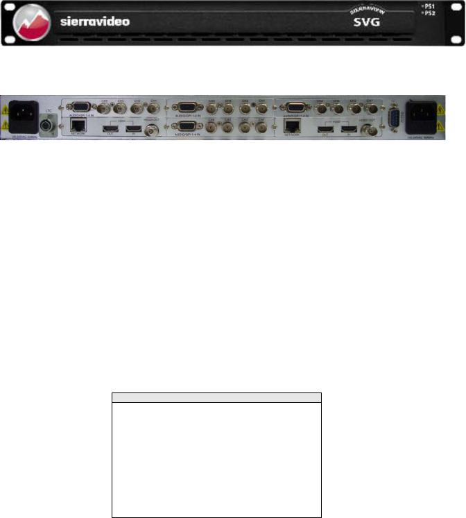
SVG
Frame Front Panel
Frame Back Panel
PS1/PS2 Lamps: Indicators with blue lights for dual power supplies operating normally.
Reset Button: HDMI/HDSDI Output Module systems only! This feature is not supported on VGAHDMI output module systems.
Accessed through the very small hole on the front panel under the PS1/PS2 lamps. This function restores the factory default for the IP address,username and password (192.168.1.76, admin, 000000). Insert a push pin into the small hole, and press the button until there is no picture from HDMI and HD/SD-SDI output (about 5 seconds). Then please restart the device, using the default IP address, username and password.
Note
The models shown here and in the subsequent sections are fully populated. In some cases, these frames may be configured with more or fewer modules.
Consult the rear panel serial number and model number to verify your order and product.
The system you receive is customized for the size & type requested at time of purchase from
Sierra Video
3

SIERRA VIDEO
Chapter2
Installation
Introduction
Installation procedures are similar for all frames covered under this manual. Exceptions, if any, have been noted in each of the following paragraphs.
Rack Mounting
Carefully inspect the frame to ensure that there has been no shipping damage. Make sure all shipping material is removed from the multi-viewer frame.
The multi-viewer described in this manual can be rack mounted in a standard 19" (RU) EIA rack assembly and includes rack "ears" at the ends of the front of the frames. It does not require spacing above or below the unit for ventilation.
To rack mount any the multi-viewer, simply place the unit's rack ears against the rack rails of the rack, and insert proper rack screws through each of the holes in the rack ears. Always rack mount the multi-viewer prior to plugging the unit into a power receptacle or attaching any cables.
CAUTION!
The operating temperature range of this product is 0 to 40ºC. Do not exceed the maximum (40ºC) or minimum (0ºC) operating temperature.
If installed in a closed or multi-rack assembly, the operating ambient temperature of the rack environment may be greater than the room ambient temperature. Therefore, consideration should be given to installing the equipment in an environment compatible with the manufacturer’s maximum rated ambient temperature.
Installation of the equipment in a rack should be such that the amount of air flow to the sides of the multi-viewer required for safe operation is not compromised.
Dimensions
The SVG multi viewer frame is 1 rack units high, 19” wide, and 20” deep.
5
SIERRA VIDEO
Notice
In order to avoid network traffic congestion, please do not submit parameters before the last modification is applied.
In order to avoid loss of communication between a web browser and the unit caused by continuous operations, please do your second operation after you have gotten the first operation's result. Generally, it will take less than three seconds to get results after you submit a command. The time is related with the monitor type. If the time is too long (over 7 seconds), there may be something abnormal with the hardware’s working status (overheating for example), please wait.
Do not plug in HDMI connectors with power on.
Without technological guidance from Sierra Video, users are not permitted to remove or insert the modules away from or into the chassis or debug the internal operation.
We do not undertake any obligation or responsibility for intentional damage to the SVG.
Built-in Web server to control the SVG easily by your computer's browser via Ethernet. Please make sure IP address of SVG is in the same network segment as your computer (first three triplets should be the same, the fourth must be unique).
Windows 2003, Windows XP, Windows Vista and Windows 7 are strongly recommended with Internet Explorer web browser.
Before powering down the SVG, the user should click the "SAVE" button (on the lower right of the web browser System GUI page) to store all current settings. Otherwise, you may lose some data. The SAVE button stores all current parameters into Flash memory.
Users can also upgrade the system under the label “Network.” Before the upgrade, any anti-virus software and firewall have to be closed to make sure that the upgrade data is transmitted to SVG system. Power and network should not be cut off during upgrading.
Please set all channels to input inner Test signal without waveform display before an upgrade. This will shorten the time to upgrade the system.
If the current output resolution of HDMI signal is not compatible with your monitor, you can change the output resolution on the web browser.
6
SVG MULTI-VIEWER
Input/ Output Rear Panel
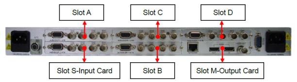
Overview
Chassis of SVG series is 1RU frame with six slots. The top row from left to right contains Slot A, Slot C and Slot D. The bottom row from left to right contains Slot S, Slot B, and Slot M. See the picture above.
Table-module type allowed inserting into each slot
Slot |
Allowed Module Type |
Slot |
Allowed Module Type |
M (Main) |
Output Card only |
B |
Input Card only |
S (Slave) |
Input Card/Output Card |
C |
Input Card only |
A |
Input Card only |
D |
Input Card only |
Note:
For Slot M only allows inserting an output card.
For Slot S, when system is single output, it allows inserting an input card; when it is dual outputs, it allows inserting an output card.
For example, when one input card is inserted into Slot A, up to four virtual channels can be created from this input card as a channel group named group A. If there is no input card inserted into Slot A, then there is no group A shown on the web browser page. This is the same for Slot B, C and D. Input signals can be only displayed in the virtual channels which are created from the same input card (any input on module A can be displayed on any of the four channels of module A, any input on module B can be displayed on any of the four channels of module B and so on).
7
SIERRA VIDEO
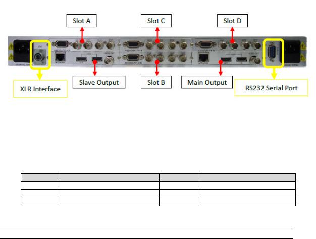
RS-232 Connection
The RS232 connector is a serial port for multiple functions. Baud rate and parity is configured on the web page. You can achieve multiple functions, such as dynamic UMD and Tally, GPS timing and remote control of layouts, but only one type of control at a time using the serial port.
RS232, DB9 definition (For TSL and GPS)
Pin # |
Function |
2 |
Rx |
3 |
Tx |
5 |
GND |
RS232 to RS232 cable (for Template recall, UMD & Tally and GPS Timing)
Pin # PC |
Pin# SVG |
2 |
3 |
3 |
2 |
5 |
5 |
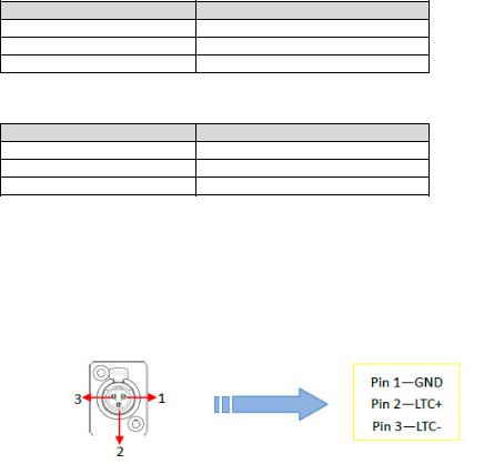
Timing Connection
This uses an XLR interface. LTC timing for the SVG is based on EBU/SMPTE time code according to IEC standards. The pin 1 is GND, and pin 2 & 3 receive LTC data. See the picture below. Checking the box “LTC” on the web page enables the LTC timing function, otherwise, timing comes from other selection. See the details about Timing Settings.
8
SVG MULTI-VIEWER
Single Output System
There is only one output card for SVG single output system. The output card can be HDSDI+HDMI output card, or VGA+HDMI output card.
Based on different quantity of input cards, the combination of the SVG configuration is described as following (the +1 refers to the HDMI input on the output module):
Qty of Output Cards |
Qty of Input Cards |
Combination |
|
|
|
1 |
1 |
5 pictures (4+1) display system |
|
|
|
1 |
2 |
9 pictures (8+1) display system |
|
|
|
1 |
3 |
13 pictures (12+1) display system |
|
|
|
1 |
4 |
17 pictures (16+1) display system |
|
|
|
1 |
5 |
21 pictures (20+1) display system |
|
|
|
9
SIERRA VIDEO
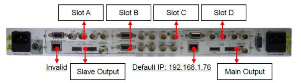
Dual Output System
For a dual outputs display system, there are two output cards, which are main output card and slave output card. See the picture above.
The main and slave output cards must be the same type (HDMI+HDSDI or HDMI+VGA). Mixing of two different type output cards is not supported.
The dual outputs are both configured by the web browser at the same time via the network interface (RJ45) on main output card. The default IP address is 192.168.1.76. And the RJ45 interface on slave output card is invalid with no function (do not connect to this RJ45 interface).
Dual outputs system can be configured to be single output system easily via web browser Configuration page (IP: 192.168.1.76/config.html then delete the second channel).
Based on different quantity of input cards, the combination of SVG is described as following (the +2 refers to the HDMI inputs on each the two output modules):
Qty of Output Cards |
Qty of Input Cards |
Combination |
|
|
|
2 |
1 |
6 pictures (4+2) display system |
|
|
|
2 |
2 |
10 pictures (8+2) display system |
|
|
|
2 |
3 |
14 pictures (12+2) display system |
|
|
|
2 |
4 |
18 pictures (16+2) display system |
|
|
|
10
SVG MULTI-VIEWER
Input Rear Panel
There are three kinds of input modules: SD/HD/3G input module, CVBS/SD-SDI input module, and HDMI input module.
SD/HD/3G Input module
Supported resolutions:
SD: 480i 60, 576i 50
HD: 720p 50Hz/60Hz
1080i 50Hz/59.94Hz/60Hz
1080p 23.976Hz/24Hz/25Hz/29.97Hz/30Hz
3G HD: 1080p 50/59.94/60
The SD/HD/3G input module supports 3G/HD/SD signals with embedded audio and indicates up to 4 audio channels of Group1.
The SD/HD/3G input module uses the mini-adapter Tally/Audio interface for Tally signals only. Analog audio signals are not supported with this input module.
11

SIERRA VIDEO
HDMI Input module
Support resolutions:
Video:
SD: 480i 59.94, 576i 50
HD: 720p 50Hz/60Hz 1080i 50Hz/60Hz
1080p 24Hz/25Hz/30Hz
1080p 50Hz/60Hz
Graphic:
1280x720px50/60Hz
1920x1080px25/30Hz
1920x1080px50/60Hz
Supports HDMI signals with embedded audio and indicates up to 4 audio channels of Group1.
Supports HDCP protocol.
12

SVG MULTI-VIEWER
CVBS/SDI Input module
|
|
|
|
|
|
|
|
|
Definition of DB15 interface; |
|
|
|
|
|
|
|
|
|
|
|
|
|
|
|
Pin # |
Definition |
Pin # |
Definition |
Pin # |
Definition |
|
|
1 |
Ch1-Aud |
6 |
GND |
11 |
|
|
|
2 |
Ch2-Aud |
7 |
Ch1-Tally |
12 |
|
|
|
3 |
Ch3-Aud |
8 |
GND |
13 |
|
|
|
4 |
Ch4-Aud |
9 |
Ch2-Tally |
14 |
|
|
|
5 |
Ch3-Tally |
10 |
GND |
15 |
|
|
Support formats
CVBS: NTSC/ PAL
SDI: 480i 60/576i 50
Support SDI signal with embedded audio and indicate up to 4 audio channels of Group1.
Audio/Tally input module supports one audio channel for each analog composite video signal.
13
SIERRA VIDEO
Output Rear Panel
There are two types of output modules: HDMI+VGA output module, and HDMI+HDSDI output modules.
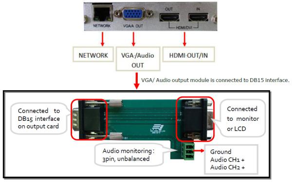
HDMI/VGA Output Card
Each output module provides VGA and HDMI dual output interfaces. Moreover, on the output module, there is a HDMI input and RJ45 interface for Web server.
Network
RJ45 interface with 10/100/1000M auto-detection. When the system has dual output cards, both output cards are configured by web server with the network interface (RJ45) on the main output card. The default IP address is 192.168.1.76. When facing the rear panel of chassis, if the output card is on the left, it is a slave output card. The RJ45 interface on the slave output is not used and has no function.
HDMI OUT
HDMI output interface. There is no audio signal embedded into HDMI output signal on the HDMIVGA Output Module, Audio is monitored via the VGA output adapter. The output resolution of the HDMI signal is up to 1920x1200X60p.
The output resolutions supported:
1024x768x60p, 1280x720x60p, 1280x768x50p 1280x768x60p, 1280x1024x60p, 1360x768x60p 1366x768x60p, 1400x1050x60p, 1680x1050x60p
1600x1200x60p, 1920x1080x50p, 1920x1080x60p, 1920x1200x60p
14
SVG MULTI-VIEWER
HDMI IN
HDMI input interface is compatible with both HDMI and DVI signals for input. It supports HDMI signals with embedded audio. There is no display of UMD and audio meters for this HDMI channel on the HDMIVGA Output Module. This module supports the HDCP protocol. The HDMI input channel is always on top of all the channels from input cards.
Supported input resolutions of HDMI/DVI signals:
Video:
SD: 480i 59.94, 576i 50 HD: 720p 50Hz/60Hz
1080i 50Hz/60Hz
1080p 24Hz/25Hz/30Hz
1080p 50Hz/60Hz
Graphic:
1280x720px50/60Hz
1920x1080px25/30Hz
1920x1080px50/60Hz
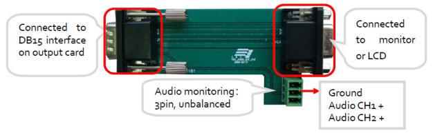
VGA Out
The VGA output uses a DB15 interface. It provides the VGA output signal and independent analog audio. The display on the VGA output is the same as HDMI output.
Supported resolutions of VGA:
1024x768x60p, 1280x720x60p, 1280x768x50p 1280x768x60p, 1280x1024x60p, 1360x768x60p 1366x768x60p, 1400x1050x60p, 1680x1050x60p 1600x1200x60p
The VGA/Audio output module can monitor two audio channels from HD/SD/HDMI inputs, and one audio channel of analog composite video inputs, which is provided by the Audio/Tally input module.
15
SIERRA VIDEO
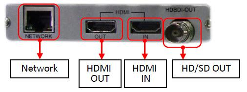
HDMI/HD/SDI Output Card
Each output module provides HDSDI and HDMI dual outputs. Plus, on each output module, there is an HDMI input and RJ45 interface for Web server connection.
Network
RJ45 interface with 10/100/1000M auto-detection. When the system has dual output cards, both output cards are configured by the web browser with the network interface (RJ45) on main output card only. The default IP address is 192.168.1.76. When facing the rear panel of chassis, if the output card is on the left, it is a slave output card. The RJ45 interface on the slave output is not used and has no function.
HDMI OUT
Two HD/SD-SDI audio channels, four HDMI audio channels, or one analog audio signal can be embedded into the HDMI output signal. Users can select audio source via the web browser control to monitor. The output resolution of HDMI signal is up to 1920x1080.
The output resolutions are provided as below: 1024x768, 1280x720, 1280x768 1280x1024, 1360x768, 1400x1050 1600x1200, 1680x1050, 1920x1080
HDMI In
HDMI input interface. It is compatible of both HDMI and DVI signal to input. And it supports HDMI signal with embedded audio. There is no display of UMD and audio meters for this HDMI channel. Supports HDCP protocol. The HDMI input channel is always on the top of all the channels from input cards.
Supported input resolutions of the HDMI/DVI signals:
Video:
SD: 480i 59.94, 576i 50
HD: 720p 50Hz/60Hz 1080i 50Hz/60Hz
1080p 24Hz/25Hz/30Hz
1080p 50Hz/60Hz
Graphic:
1280x720px50/60Hz
1920x1080px25/30Hz
1920x1080px50/60Hz
16
 Loading...