

Page 1
UPC-166
Upconverter
with Analog/SDI Input, Audio Embed/De-Embed,
Frame
Sync, Timecode and Closed Caption
Support
Owner's Manual
Sierra Video Systems
UPC-166-OM
Version 4.0
Page 2
Manual No.: UPC-166-OM
Document
Version: 4.0
Release Date: October 1, 2009
Applicable for
Software
Version: 4.0 / 2701
Copyright
©Copyright 2009, Sierra Video. All Rights Reserved.
Duplication or distribution of this manual and any information contained within is strictly prohibited without the express written
permission of Sierra Video. This manual and any information contained within, may not be reproduced, distributed, or
transmitted in any form, or by any means, for any purpose, without the express written permission of Sierra Video. Reproduction
or reverse engineering of software used in this device is prohibited.
Disclaimer
The information in this document has been carefully examined and is believed to be entirely reliable. However, no
responsib
ilit
y
is assumed for inaccuracies. Furthermore, Sierra Video reserves the right to make changes to any products herein to improve
readability, function, or design. Sierra Video does not assume any liability arising out of the application or use of any product or
circuit described herein.
Trademark Information
is a registered trademark of Ross Video Limited.
is a registered trademark of Sierra Video Systems
DashBoard™ and openGear™ are trademarks of Ross Video Limited. Dolby® is a registered trademark of Dolby Laboratories,
Inc. Other product names or trademarks appearing in this manual are the property of their respective owners.
2.0-to-5.1 audio upmixer licensed feature uses the AutoMAX-II™ upmix algorithm provided under license from
Linear Acoustic Inc. Linear Acoustic, the "LA" symbol, UPMAX, AutoMAX, and AutoMAX-II are trademarks of Linear
Acoustic Inc. All Rights Reserved.
UPC-166-OM
Congratulations on choosing the Sierra Video UPC-166 Upconverter with Analog/SDI Input, Audio Embed/DeEmbed, Frame Sync, Timecode and Closed Caption Support. The UPC-166 is part of a full line of modular
processing and conversion gear for broadcast TV environments. The Sierra Video line includes video decoders
and encoders, audio embedders and de-embedders, distribution amplifiers, format converters, remote control
systems and much more. Should you have questions pertaining to the installation or operation of your UPC166, please contact us at the contact information on the front cover.
Page 3

Table of Contents
Chapter 1
Introduction . . . . . . . . . . . . . . . . . . . . . . . . . . . . . . . . . . . . . . . . . . .
Overview ..............................................................................................................
UPC-166 Card Software Versions and this Manual .............................................
Manual Conventions .............................................................................................
Warnings, Cautions, and Notes ................................................................
Labeling Symbol Definitions....................................................................
Safety Summary ...................................................................................................
Warnings...................................................................................................
Cautions ....................................................................................................
UPC-166 Functional Description..........................................................................
UPC-166 Input/Output Formats ...............................................................
Video Processor Description ....................................................................
Audio Processor Description ...................................................... .............
AES Audio Input Advanced Features ......................................................
User Control Interface ..............................................................................
UPC-166 Rear I/O Modules .....................................................................
Contact Sierra Video. ..............................................................................................
1-1
1-1
1-2
1-3
1-3
1-4
1-4
1-4
1-4
1-5
1-5
1-7
1-12
1-18
1-19
1-21
1-23
1-24
1-28
1-28
1-29
Chapter 2
Installation and Setup . . . . . . . . . . . . . . . . . . . . . . . . . . . . . . . . . . .
Overview ..............................................................................................................
Setting I/O Switches for AES I/O (1-4) Ports ......................................................
Installing the UPC-166 Into a Frame Slot ............................................................
Installing a Rear I/O Mod......................................................................................
UPC-166 Rear I/O Modules .....................................................................
Setting Up UPC-166 Network Remote Control
2-1
2-1
2-1
2-2
2-4
2-6
2-9
i
UPC-166-OM
Page 4

Chapter 3
Operating Instructions . . . . . . . . . . . . . . . . . . . . . . . . . . . . . . . . . . .
Overview ................................................................................................................
Control and Display Descriptions ..........................................................................
Function Submenu/Parameter Submenu Overview ...................................
UPC-166 Card Edge Controls, Indicators, and Display .............................
DashBoard™ User Interface ......................................................................
Remote Control Panel User Interfaces ......................................................
Accessing the UPC-166 Card via Remote Control ...............................................
Accessing the UPC-166 Card Using DashBoard™ ..................................
UPC-166 Function Submenu List and Descriptions .............................................
Video Signal Controls ..............................................................................
Audio Input Controls ................................................................................
Video Proc ................................................................................................
Scaler ........................................................................................................
AFD ..........................................................................................................
Overlays ...................................................................................................
Framesync ................................................................................................
Embedded Audio Group 1/2 ....................................................................
Embedded Audio Group 3/4 ....................................................................
AES Audio Out Pairs 1-4 .........................................................................
AES Audio Out Pairs 5-8 .........................................................................
Dolby Metadata ........................................................................................
Closed Captioning ....................................................................................
Timecode ..................................................................................................
Audio Mixing ...........................................................................................
Tone Generator .........................................................................................
Licensable Features ..................................................................................
Presets ......................................................................................................
Audio Routing Example Using DashBoard™ ..........................................
Troubleshooting ....................................................................................................
Error and Failure Indicator Overview .......................................................
Basic Troubleshooting Checks..................................................................
UPC-166 Processing Error Troubleshooting.............................................
Troubleshooting Network/Remote Control Errors....................................
In Case of Problems ..................................................................................
3-1
3-1
3-1
3-2
3-3
3-8
3-11
3-12
3-12
3-13
3-14
3-15
3-16
3-17
3-18
3-21
3-23
3-28
3-32
3-36
3-40
3-46
3-48
3-53
3-54
3-55
3-56
3-60
3-64
3-64
3-65
3-67
3-70
3-70
3-74
3-75
3-78
3-78
ii
UPC-166-OM
Page 5

Chapter 1
Introduction
Overview
This manual provides installation and operating instructions for the
UPC-166 Upconverter with Analog/SDI Input, Audio Embed/De-Embed,
Frame Sync, Timecode and Closed Caption Support card (also referred to
herein as the UPC-166).
This manual consists of the following
chapters:
• Chapter 1,
“Introduction”
– Provides information about this manual
and what is covered. Also provides general information regarding the
UPC-166.
• Chapter 2, “Installation and Setup” – Provides instructions for
installing the UPC-166 in a frame, and optionally installing UPC-166
Rear I/O Modules.
• Chapter 3, “Operating Instructions” – Provides overviews of
operating controls and instructions for using the UPC-166.
This chapter contains the following
information:
• UPC-166 Card Software Versions and this Manual (p. 1-2)
• Manual Conventions (p. 1-3)
• Safety Summary (p. 1-4)
• UPC-166 Functional Description (p. 1-5)
• Technical Specifications (p. 1-24)
• Warranty and Service Information (p. 1-28)
• Contact Sierra Video. (p. 1-29)
1-1
UPC-166-OM
Page 6

1
UPC-166 Card Software Versions and this Manual
UPC-166 Card Software Versions and this Manual
When applicable, Sierra Video. provides for continual COMPASS™ card
product enhancements through software updates. As such, functions
described in this manual may pertain specifically to cards loaded with a
particular software build. Sierra Video. releases an updated manual
whenever a card’s software is updated. If you received your UPC-166 and
this manual at the same time, this manual reflects all facets of your
card.
This manual (UPC-166-OM (V4.0)) was specifically written for
Software Version: 4.0 / 2701
If your card was purchased earlier than receiving this manual, you can check
the Software Version of your card and see if it matches the Software Version
covered by this manual.
If necessary, the Software Version of your card can be checked by viewing
this information as displayed on the Info submenu on the card-edge display,
or by checking the Card Info menu in DashBoard™. See Checking UPC-
166 Card Information (p. 3-14) in Chapter 3, “Operating Instructions” for
more information.
Proceed as follows if your card’s software does not match this manual:
1-2
UPC-166-OM
Card Software earlier than
version in manual
Card is not loaded with the latest software. Not all
functions described in this manual may be
available.
If desired, contact Sierra Video to receive the
latest Update software for your card. Software is
typically sent by e-mail.
You can update your card by uploading the new
Update software by going to the
Support>Downloads link at
www.sierravideo.com. Then, go to the listing for
your card and download ―COMPASS™ Firmware
Update Guide.‖
Card Software newer than
version in manual
A new manual is expediently released whenever a
card’s software is updated and specifications
and/or functionality have changed as compared
to an earlier version (a new manual is not
necessarily released if specifications and/or
functionality have not changed). A manual earlier
than a card’s software version may not completely
or accurately describe all functions available for
your card.
If your card shows features not described in this
manual, you can check for the latest manual (if
applicable) and download it by going to the
Support>Downloads link at
www.sierravideo.com.
Page 7

Introduction
Manual Conventions
Manual Conventions
In this manual, display messages and connectors are shown using the exact
name shown on the UPC-166 itself. Examples are provided below.
• Card-edge display messages are shown like this:
• Connector names are shown like this: AES IN 8
In this manual, the terms below are applicable as follows:
• UPC-166 refers to the UPC-166 Upconverter with Analog/SDI
Input, Audio Embed/De-Embed, Frame Sync, Timecode and Closed
Caption Support card.
• Frame refers to the 8310 (or similar) frame that houses the
openGear cards.
• Device and/or Card refers to an openGear card.
• System and/or Video System refers to the mix of interconnected
production and terminal equipment in which the UPC-166 and
other openGear cards operate.
Warnings, Cautions, and Notes
Certain items in this manual are highlighted by special messages. The
definitions are provided below.
Warnings
Warning messages indicate a possible hazard which, if not avoided, could
result in personal injury or death.
Cautions
Caution messages indicate a problem or incorrect practice which, if not
avoided, could result in improper operation or damage to the product.
Notes
Notes provide supplemental information to the accompanying text. Notes
typically precede the text to which they apply.
1-3
UPC-166-OM
Ch01
Page 8
1
Safety Summary
Labeling Symbol Definitions
Safety Summary
Warnings
To reduce risk of electric shock do not remove line voltage service barrier cover on frame
equipment containing an AC power supply. NO USER SERVICEABLE PARTS INSIDE.
REFER SERVICING TO QUALIFIED SERVICE PERSONNEL.
Cautions
This device is intended for environmentally controlled use onl y in appropriate video
terminal equipment operating environments.
This product is intended to be a component product of an openGear™ frame. Refer to the
openGear™ frame Owner's Manual for important safety instructions regarding the proper
installation and safe operation of the frame as well as its component products.
Heat and power distribution requirements within a frame may dictate specific slot
placement of cards. Cards with many heat-producing components should be arranged to
avoid areas of excess heat build-up, particularly in frames using only convection cooling.
The UPC-166 has a moderate power dissipation (24 W max.). As such, avoiding placing
the card adjacent to other cards with similar dissipation values if possible.
If required, make certain Rear I/O Module(s) is installed before installing the UPC-166 into
the frame slot. Damage to card and/or Rear I/O Module can occur if module installation is
attempted with card already installed in slot.
If card resists fully engaging in rear I/O module mating connector, check for alignment and
proper insertion in slot tracks. Damage to card and/or rear I/O module may occur if
improper card insertion is attempted.
1-4
UPC-166-OM
CAUTION
CAUTION
CAUTION
CAUTION
CAUTION
! WARNING !
Attention, consult accompanying documents.
Electronic device or assembly is susceptible to damage from an ESD
event. Handle only using appropriate ESD prevention practices.
If ESD wrist strap is not available, handle card only by edges and avoid
contact with any connectors or components.
Symbol (WEEE 2002/96/EC)
For product disposal, ensure the following:
• Do not dispose of this product as unsorted municipal waste.
• Collect this product separately.
• Use collection and return systems available to you.
Page 9

Introduction
UPC-166 Functional Description
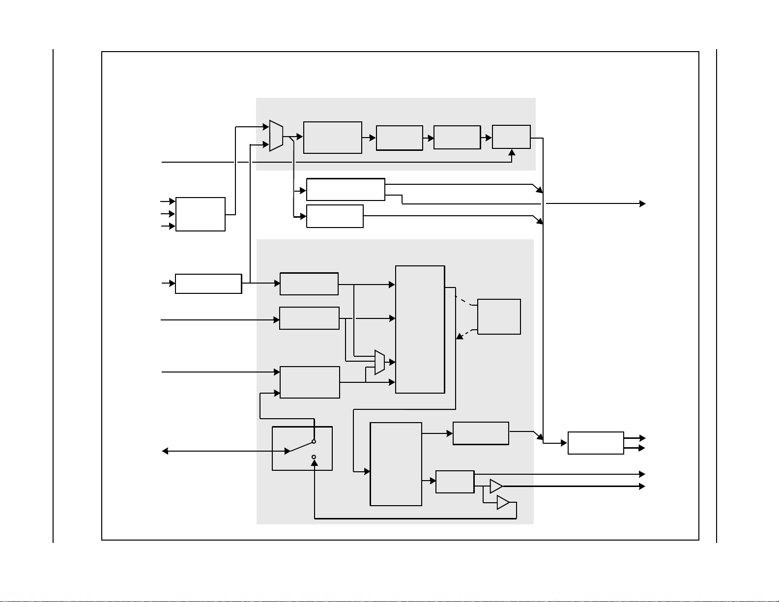
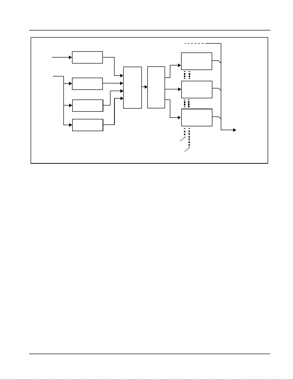
UPC-166 Functional Description
Figure 1-1 shows a functional block diagram of the UPC-166. The UPC166 upconverter also includes a full 16-channel audio embedder/deembedder, a 12-bit analog-to-digital video converter, an 8-channel, 24-bit
balanced analog-to-digital audio converter, and a full video frame
synchronizer. The UPC-166 also handles AFD code detection and
processing, timecode support, closed captioning support, and transfer of
Dolby® metadata.
As such, the UPC-166 is highly suited as a universal SD-to-HD input
processing card with comprehensive audio and video support. The video
source can be either an SD-SDI input or a SD analog video input. The upconverted video aspect ratio can be corrected to provide proper output
aspect.
Note:
Some of the functions described below are available only when using the
DashBoard™, or Cobalt® OGCP-9000 or OGCP-9000/CC Control Panels
user interfaces. Refer to User Control Interface (p. 1-19) for user
interface descriptions.
UPC-166 Input/Output
The UPC-166 provides the following inputs and outputs:
• Inputs:
• SD-SDI IN – SD-SDI input
• Y/Cmpst IN, Pr/C IN, Pb IN – analog composite/component video
inputs
• AES I/O (1-4) – user-switchable as AES inputs or AES outputs
• AES IN (5-8) – dedicated AES inputs
• AN-AUD IN (1-8) – balanced analog audio inputs
• Outputs:
• SDI OUT – two dual-rate HD/SD-SDI buffered video outputs
• AES OUT (1-8) – dedicated AES outputs
• AES I/O (1-4) – user-switchable as AES inputs or AES outputs
• DOLBY META – RS485 Dolby
®
metadata output
Note:
The input/output complement listed above represents the maximum
capability of the UPC-166. The practical input/output complement is
determined by the par- ticular Rear I/O Module used with the UPC-166.
Refer to UPC-166 Rear I/O Modules (p. 1-21) for more information.
1-5
UPC-166-OM
Page 10
ility.
Refer to ―UPC-
Y/Cmpst IN
META
IN (1-8)
AES OUT
(1-4)
1
UPC-166 Functional Description
Figure 1-1 UPC-166 Functional Block
1-6
UPC-166-OM
tes: 1. Signal connections shown depicts
signal
ed by
Rear
21 for
more
EXT REF
IN (1,2)
mixer
DOLBY
Pr/C IN
Pb IN
SD-SDI IN
AN-AUD
ono
with new 5.1 mix.
AES IN (5-8)
2.0-to-5.1 upmixer;
HD/SD
AES I/O (1-4)
SDI OUT
(5-8)
UPC-166BD_WDMO
Processor
No
full input/output capab
Practical input/output
availability is determin
I/O Module used.
Rear I/O Modules,‖ 1-
information.
2. Optional 2.0-to-5.1 up
licensable feature.
Serializer/
Cable Drivers
Frame
Sync
Metadata Extract/
Re-insert
Video
A/D
Au
dio Processor
Down/
Active:
Overwrites
6
selected channels
See
text.
Bypass:
Bypasses
all original channels
pass unaffected.
ES IN (1-4)]
EQ/Deserialize
[A
Audio
Embed
S1
1–S14
AES
Encode
[AES OUT (1-4)]
Framesync
Tracking
Delay
and
User
Offset
AES Decode
and SRC
2.0-to-5.1
Upmixer
(NOTE 2)
Audio
De-Embed
Analog
Audio
A/D
M
Mixe
r
Audio
Routing/
Gain
Control
TC/CC
Processing
AFD
Processing
Video
Processing
Upconversion
Page 11

Introduction
UPC-166 Functional Description
Video Processor Description
The UPC-166 features a scaler that provides up-conversion using deinterlacing and motion adaptation for high quality up-conversions. The
scaler also provides user-adjustable aspect ratio control and zoom control.
The UPC-166 video subsystem also provides the functions described
below.
Video Processor
The UPC-166 provides full color processing control (luma gain and lift,
chroma saturation, and color phase) of the output video.
Frame Sync Function
This function provides for frame sync control using either one of two
external EXT REF IN (1,2) reference signals distributed with the card frame, or
the input video as a frame sync reference.
This function also allows horizontal and/or vertical offset to be added
between the output video and the frame sync reference.
A video/audio delay offset function allows adding or reducing audio delay
from the matching video delay. This function is useful for correcting lip sync
problems when video and audio paths in the chain experience
differing
overall
delays. A Reset Framesync function resets the frame sync following
any horizontal or vertical offset changes, clearing any buffered audio and
video and re-establishing the frame sync. The UPC-166 re-establishes
video/audio sync following framesync changes by applying an offset in small,
progressive amounts to provide a seamless, glitch-free retiming. A userselectable hard resync function allows setting a threshold at which hard
resync is applied if audio-video offset exceeds a selectable threshold. Hard
resync
provides fastest
snyc-up suitable for off-air manipulation. Conversely,
a threshold setting that avoids hard resync allows glitch-free on-air
manipulation.
In the event of input video loss of signal, this function provides for disabling
the video, going to a desired color raster, or freezing to the last intact frame
(for SDI, last frame having valid SAV and EAV codes; for analog, last frame
free of timing errors).
1-7
UPC-166-OM
Page 12
1
UPC-166 Functional Description
Scaler Function
The scaler function provides up-conversion from standard SD formats. It
provides up-conversion to multiple frame rates, film frame rates, and
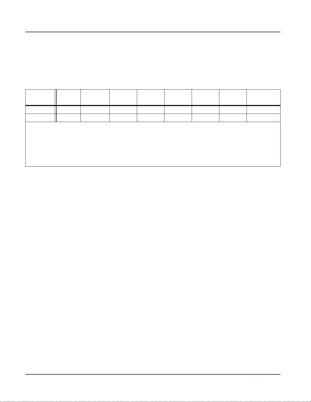
up-conversion to interlaced and progressive formats. Table 1-1 lists the UPC166 conversion choices available for various input formats and frame rates.
Table 1-1
Scaler Function Conversions
(film rates)
When output video is set to 720p, the 720p output can be converted to 720p
half-rate formats as listed in Table 1-1. When output video is set to 1080 film
(1080p23.98), the UPC-166 can convert the output to 1080PsF23.98
(segmented frame progressive).
The scaler function also provides aspect ratio conversion that provides a
choice from several standard aspect ratios. Additionally, user-defined and
“Follow AFD Settings” conversion can be applied. User defined settings
allow custom user-defined H and V aspect ratio control. “Follow AFD
Settings” sets the output aspect ratio to track with AFD (Active Format
Description) settings embedded in the received video signal.
Timecode Processor
(See Figure 1-2.) This function provides for extraction of timecode data from
the input video, and in turn re-insertion of timecode data into the output SDI.
In this manner, timecode data can be preserved, even after format conversion.
The function can monitor both the analog and SDI video inputs of the card for
supported timecode formats, and then select and prioritize among analog
VITC, SDI VITC, SDI ATC_VITC, and SDI ATC_LTC timecode sources. If
the preferred format is detected, the preferred format is used by the card; if the
preferred format is not detected, the card uses other formats (where available)
as desired.
The function also provides conversion between various timecode formats and
provides independent insertion and line number controls for each SDI
timecode output format.
1-8
UPC-166-OM
Input
Format
SD
(NTSC/
PAL)
720p
720p
half-rate
720p
(film
rates)
1080i
1080p
1080p
(film
rates)
1080PsF
525i 59.94
525i 59.94
720p 59.94
720p 29.97
720p 23.98
(4)
1080i 59.94
1080p 29.97
1080p 23.98
(4)
1080PsF 23.98
(4)
625i 50
625i 50
720p 50
720p 25 X
1080i 50
1080p 25 X X
Notes: 1. The drop-down list choice of ―Same as Input‖ is used when no conversion is desired. For clarity, it is not redundantly listed here.
2. ―X‖ denotes conversions not available or invalid conversions.
3. Interlaced formats rates listed are field rates. Progressive format rates listed are frame rates.
4. If the original material does not have a proper 3-2 cadence suitable for conversion to film rates, the conversion reverts to standard
de-interlacing. While this video can be converted to film rates, the resulting image motion will lack smoothness. Therefore, make
certain interlaced video is appropriately constructed for 3-2 reverse pulldown when converting video to film rates. See 3-2
Pulldown Conversion and Considerations (p. 1-11).
5. ―NTSC‖ and ―PAL‖ in this manual informally denote 486i5994 and 575i50 SD-SDI video formats.
Page 13
Introduction
UPC-166 Functional Description
Video
Detect/Extract
Video Output
Figure 1-2 Timecode Processor
Closed Captioning Processor
This function provides support for closed captioning setup. When
enabled,
the
function selects from current input video, analog SD, or SDI as the source
of closed captioning data. The function also allows the selection of the
ancillary data line number where the ancillary closed caption data is outputted
when the output is HD.
1-9
UPC-166-OM
HD/SD–SDI
(From Video Proc)
Analog
Input
SDI
Video
Input
HD/SD–SDI
Insert
Control
Line
Number
Control
SDI ATC_LTC
Detect/Extract
SDI ATC_VITC
Detect/Extract
SDI VITC
Priority/
Select
Buffer/
Format
Analog VITC
Detect/Extract
SDI
VITC
Timecode
Proc/Embed
ATC_VITC
Timecode
Proc/Embed
ATC_LTC
Timecode
Proc/Embed
Page 14

1
UPC-166 Functional Description
Dolby® Metadata Extractor/Re-inserter
This function extracts and preserves Dolby® metadata from the input SDI, and
in turn allows the metadata to be re-inserted in the output SDI. This allows
scaling and/or format conversions without losing Dolby® metadata. (The
UPC-166 does not offer Dolby® decoding or encoding, but will pass Dolby
®
E and/or Dolby
®
Digital™ encoded signals and metadata intact.) The
extracted metadata is buffered and then output on a user-selectable line
number on the SDI output, and on the DOLBY META RS485 connector (on
cards equipped with appropriate Rear I/O Module).
AFD Processor
This function provides aspect ratio controls and assignment of AFD codes to
the SDI output video.
Using this function, aspect ratios in accordance with the standard 4-bit AFD
codes can be applied to the output video. Additionally, custom aspect ratios
can be independently defined for any of the AFD codes.
Separate, independent AFD controls are provided for both 16:9 coded and 4:3
coded frames.
This function also provides AFD-controlled ARC by checking for any
existing AFD code within the received video input. If a code is present, the
code is displayed. With the Scaler function Aspect Ratio Conversion set to
Follow AFD Settings, the H and V settings corresponding to the received code
are applied to the video by the UPC-166. The default, standard aspect ratio
described by the AFD code can be applied, or custom horizontal/vertical
scaling can be applied for a given code.
The function also allows the selection/changing of the AFD code ancillary
data line number for the outputted AFD code.
1-10
UPC-166-OM
Page 15
Introduction
UPC-166 Functional Description
3-2 Pulldown Conversion and Considerations
Figure 1-3 depicts the 3-2 pulldown process used for conversions between
progressive film video formats and interlaced video formats. (Although the
term “3-2” is used here per convention, it is more accurately described as 2-3
per the diagram here and SMPTE definitions which stipulate that first film
frame A be represented exclusively by 2 fields from the same frame). As
shown in Figure 1-3, the term 2-3 is derived from the pattern, or cadence, in
which four consecutive film video frames are converted into five consecutive
interlaced video frames (i.e., 10 interlaced video fields). Odd and even interlaced fields are denoted in Figure 1-3 by “O” and “E” (for example, “AO” and
“AE”). Note the considerations described in Figure 1-3 for converting to film
rates.
Figure 1-3
3-2 Pulldown and Reverse Pulldown
1-11
UPC-166-OM
0p 24
[1
O 1E
]
[2
O 2E
]
[4
O 3E
]
[5
O 5E
]
[1
O 1E
]
[2
O 2E
]
[4
O 3E
]
[5
O 5E
]
3-2 Pulldown
(From 1080p 24 To 1080i 60)
―2‖ por
frame.
conten
108
1080i 60
tions consist of two consecutive interlaced fields sourced from the same film
The first film frame and first video frame are unique as a set in that their
ts are mutually and exclusively related to each other.
―3‖ portions consist of three consecutive interlaced fields sourced from the
same film frame distributed across three consecutive interlaced fields.
2 3
2
3
2 3
2
3
1
2
3
4
5
1
2
3
4
5
X X
X X
A
O AE
B
O BE
C
O CE
D
O DE
A
O AE
B
O BE
C
O CE
D
O DE
Using reverse pulldown, each film video frame is constructed from 2 interlaced fields with odd and even fields selected
as shown. The conversion pattern shown reverses the pulldown, thereby restoring the original signal.
Note: If the original interlaced material does not have the cadence described here, the conversion reverts to standard
de-interlacing. While this video can be converted to film rates, the resulting image motion will lack smoothness.
Therefore, make certain
interlaced
video is
appropriately constructed
for
reverse pulldown
when
converting
video to film
rates. Similarly, formats using a 30/29.97 Hz progressive frame rate can be converted to a 24/23.98 Hz progressive
frame rate, however some image motion irregularity will appear in the converted output.
1080i 60
108
3-2 Reverse Pulldown
From 1080i 60 To 1080p 24
D
C
B
A
D
C
B
A
A
O AE
B
O BE
B
O CE
C
O DE
D
O DE
A
O AE
B
O BE
B
O CE
C
O DE
D
O DE
D
C
B
A
D
C
B
A
Page 16

1
UPC-166 Functional Description
Audio Processor Description
The audio processor operates as an internal audio router. The router function
chooses from the following inputs:
• 16 channels of embedded audio from the SDI video
• 16 channels (8 pairs) of discrete AES input
• 8 channels of balanced analog audio input
• Four independent internal tone generators (described below)
• Digital silence (mute) setting
• Internal Down Mix and Mono Mixer outputs (described below)
The router function provides the following audio outputs:
• 16 channels of embedded audio on the SDI output
• 16 channels of discrete AES output on eight AES pairs
The router acts as a full audio cross point. Each of the 32 output channels (16
embedded AES, 16 discrete AES) can receive signal from any one of the 40
(16 embedded AES, 16 discrete AES, 8 analog) input channels, four internal
tone generators, or several mixer outputs. Unused output channels can be
mapped to a “Silence” source. Each output also provides gain adjustment and
selectable polarity inversion.
Output audio rates are always 48 kHz locked to output video, but discrete
AES inputs can pass through the sample rate converters to align these inputs
with the output timing. (AES must be nominally 48 kHz input; 32, 44.1, 96,
and 192 kHz inputs are not compatible with the UPC-166.) The sample rate
converters are disabled by default. Output AES is always precisely
synchronized with the output video. The balanced analog audio input is
sampled at 48 kHz with a +24 dBu clipping level (+24 dBu => 0 dBFS).
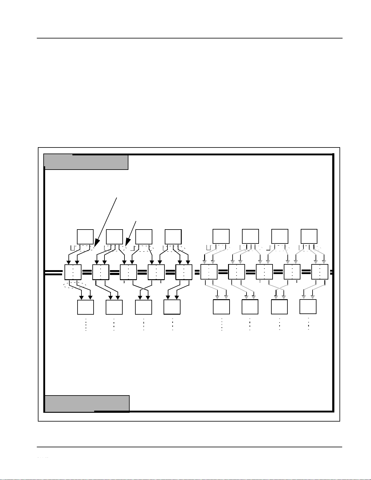
As set with the default settings, the routing between embedded audio channels
Embed Ch 1 thru Embed Ch 16 and discrete AES audio channels AES Ch1 thru
AES Ch 16 is as shown in Figure 1-4. In this mode, the routing is basic 1-to-1
embedding/de-embedding for the 16 embedded and AES discrete audio
channels. Other sources and/or destinations (described below) for each
channel are selected using the card edge controls or a remote control system.
Note: As shown in Figure 1-1, the UPC-166 is equipped with eight discrete AES
input pair ports and eight discrete AES output pair ports. On Rear I/O Modules
hav- ing limited AES I/O capabilities, switches S11 thru S14 allow available
rear module BNC connectors to be allotted between AES inputs and outputs
as desired. Buffered copies of AES OUT (1-4) are available as dedicated
outputs and as respective outputs fed through S11 – S14 on the UPC-166
card.
1-12
UPC-166-OM
Page 17
Introduction
UPC-166 Functional Description
AES Ch 1
•
•
Embed Ch 1
•
•
AES Ch 9
AES Ch 16
Figure 1-4 Default Embed/De-Embed Audio Routing
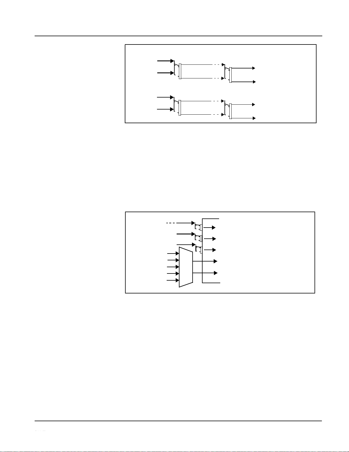
Audio Down Mixer and Mono Mixer Function
(See Figure 1-5.) The Audio Down Mixer function provides for the selection
of any five embedded, AES discrete, or analog audio sources serving as Left
(L), Right (R), Center (C), Left Surround (Ls), and Right Surround (Rs)
individual signals to be multiplexed into a stereo pair (Down Mix Left (DM-L)
and Down Mix Right (DM-R)). The resulting stereo pair DM-L and DM-R can in
turn be routed and processed just like any of the other audio sources described
earlier.
Figure 1-5 Audio Mixing Functional Block Diagram with Example Sources
1-13
UPC-166-OM
Embed Ch 1 - Ch 16
AES Ch 1 - Ch 16
AN-AUD Ch 1- Ch 8
Embedded Ch 1
Ls
Embedded Ch 2
L
AES Ch 6
C
Embedded Ch 4
R
Embedded Ch 5
Rs
DM-L
DM-R
Embedded Audio
AES Audio
Out
Group 1/2
Pairs
1-4
•
AES Ch 1
AES Ch 8
Embedded Audio
AES Audio
Out
Group 3/4
Pairs
5-8
AES Ch 9
•
Embed Ch 9
•
•
•
•
AES Ch 16
•
•
•
Embed Ch 16
•
•
AES Ch 8
•
•
•
Embed Ch 8
Page 18
1
UPC-166 Functional Description
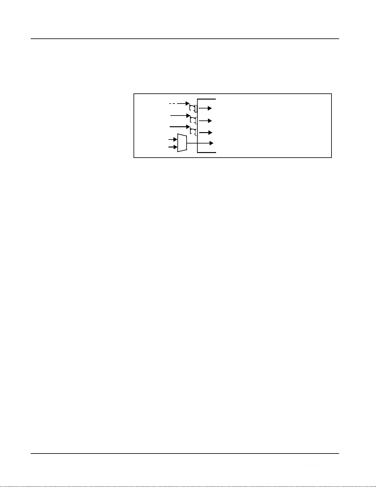
The Mono Mixer function (Figure 1-6) generates an additional mono-mixed
channel from two selected embedded, AES discrete, or analog input
channels serving as left and right inputs. The resulting mono mix channel
MONO can in turn be routed and processed just like any of the other audio
sources described earlier.
Σ
Figure 1-6 Audio Mono Mix Functional Block Diagram with Example Sources
2.0-to-5.1 Upmix Function
Upmix function is an optional licensable feature. This function and its controls
appear only when a license key is entered and activated. (This option (identified in Sierra Video price lists as ―OPT-SW-UM‖) can be purchased upon
initial order, or field-activated using a key string which is sent to you when this
option is purchased.)
The 2.0-to-5.1 upmixer function receives a normal PCM stereo pair from the
Audio Routing/Gain Control function and upmixes the pair to provide 5.1
channels (Left (L), Right (R), Center (C), Low Frequency Effects (LFE), Left
Surround (Ls), and Right Surround (Rs)). Whenever the upmixer is active, it
overwrites the six selected channels with the new 5.1 upmix signals
(including replacing the original source stereo L and R inputs with new L and
R signals).
Note:
The 2.0-to-5.1 upmixer can be set to up mix in any of three modes: Always
upmix, Bypass upmix, or Auto enable/bypass upmixing. The Auto
upmixing mode looks at the signal levels on the selected channels and
compares them to a selectable level threshold. It then determines whether or
not to generate 5.1 upmixing from the stereo pair as follows:
• If the upmixer detects signal level below a selected threshold on all
four of the selected channels designated as C, LFE, Ls, and Rs, this
indicates to the upmixer that these channels are not carrying 5.1. In
this case, the upmixer overwrites all six selected channels with the
new 5.1 content.
• If the upmixer detects signal level above a selected threshold on any
of the four selected channels designated as C, LFE, Ls, and Rs, this
indicates to the upmixer that the channel(s) are already carrying
viable 5.1 content. In this case, the upmixer is bypassed, allowing the
original channels to pass unaffected.
1-14
UPC-166-OM
Emb Ch 1 - Ch 16
AES Ch 1 - Ch 16
AN-AUD Ch 1- Ch 8
Emb Ch 12
L
Emb Ch 16
R
MON
Page 19
Introduction
UPC-166 Functional Description
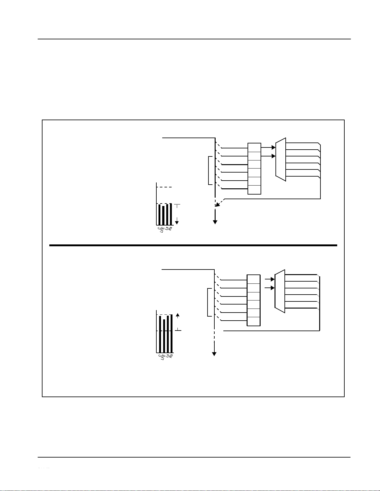
The examples in Figure 1-7 show the automatic enable/disable up-mixing
function applied to example selected channels Emb Ch 1 thru Emb Ch 6. As
shown and described, the processing is contingent upon the signal levels of
the channels selected to carry the new 5.1 upmix relative to the selected
threshold (in this example, -60 dBFS). Note also that this function is applied
after the Audio Routing/Gain Control function. Because all audio inputs pass
through the Audio Routing/Gain Control function before the up mixer, the up
mixer can use embedded, AES discrete, and/or analog audio sources.
Control
>
Detect
Emb Ch 3 – Ch 6 below
overwrites with new 5.1.
upmix content.
(Overwrite)
Control
>
Detect
on Emb Ch 3 – Ch 6 above
Figure 1-7 Up Mix Auto Enable/Bypass with Example Sources
1-15
UPC-166-OM
From
Audio
Routing/Gain
Emb Ch 1 – Ch 16
Threshold
5.1 Up
Mix
With all
detected
signal
levels
on
threshold
- 20
dBFS
- 60 dBFS
Selected channels Emb Ch 1 – Ch 6
Below Threshold
are overwritten with the new
5.1
To
Audio
Embed
From Audio
Routing/Gain
Emb Ch 1 – Ch 16
Threshold 5.1 Up
Mix
With
any
threshold, upmixer is
bypassed.
- 20
dBFS
(Bypass)
- 60 dBFS
X
Because the selected channels
are
already carrying viable content,
upmixing is bypassed, allowing the
six original Emb Ch 1 – Ch 6 to pass
unaffected.
To
Audio
Embed
Note: In either case shown here, the unselected
channels (in this example, Emb Ch 7 thru Ch
16) are not involved in this process and always
pass unaffected.
X
X
Emb Ch 1
L
Emb Ch 2
R
Emb Ch 3
(C)
Emb Ch 4
(LFE)
Emb Ch 5
(Ls)
Emb Ch 6
(Rs)
detected signal levels
Above Threshold
L
– Emb Ch 1
R
– Emb Ch 2
C
– Emb Ch 3
LFE
– Emb Ch 4
Ls
– Emb Ch 5
Rs
– Emb Ch 6
Emb Ch 1
L
Emb Ch 2
R
Emb Ch 3
(C)
Emb Ch 4
(LFE)
Emb Ch 5
(Ls)
Emb Ch 6
(Rs)
Page 20

1
UPC-166 Functional Description
Tone Generator Function
The UPC-166 contains four built-in tone generators (Tone Generator 1 thru
Tone Generator 4). Each of the four tone generators can be set to a different
frequency, and are available as audio sources for the embedded or AES audio
outputs.
18 discrete sine wave frequencies are available, ranging from 50 Hz to 16 kHz
(default frequency is 1.0 kHz).
Audio Routing Example
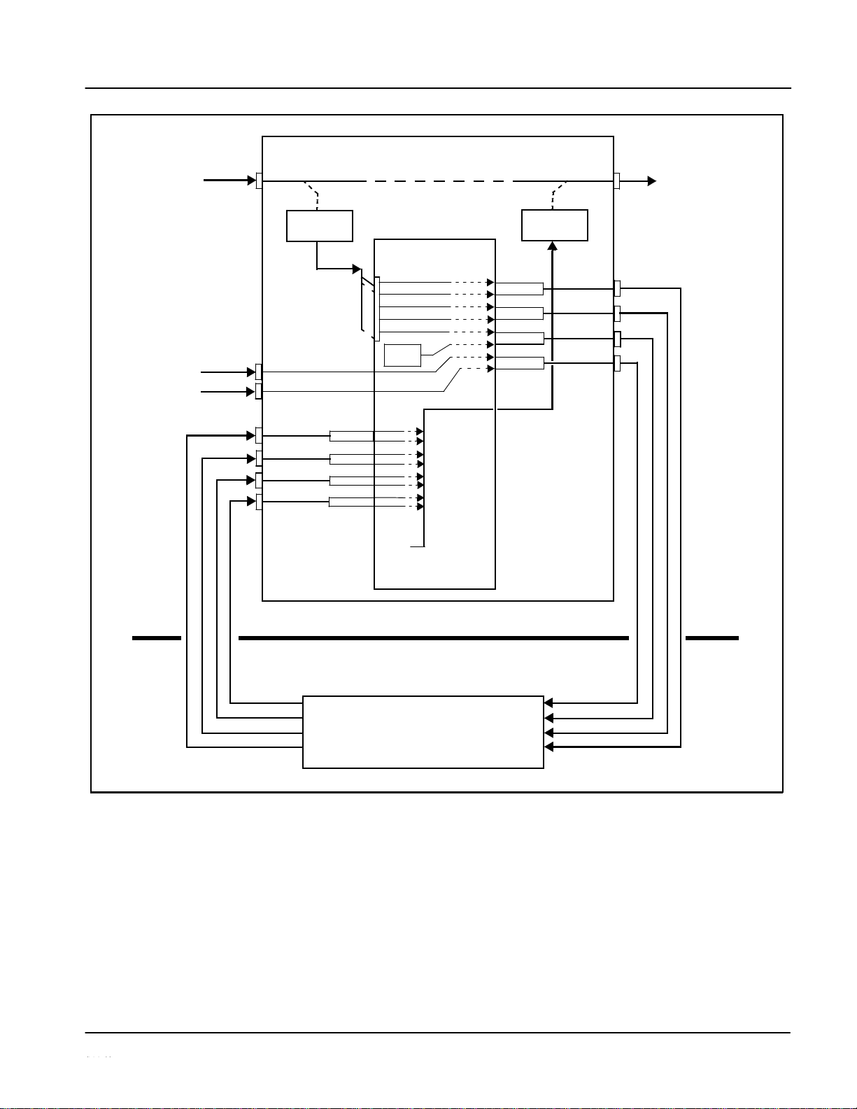
Figure 1-8 shows an example of using the UPC-166 audio embedding/
de-embedding and routing functions to de-embed audio, route the audio to
discrete outputs for post-production processing (in this example, a console
used for post-production EQ, levels, and monitor), and finally re-embed the
audio into the SDI video output. Additionally, the example shows how
external analog and internal tone generator sources can be embedded into the
SDI output (in this example, a provision for local station ID voice-over analog
and a tone).
Note that the source and destination correlations shown here are only
examples; any source can route to any destination.
1-16
UPC-166-OM
Page 21
Introduction
UPC-166 Functional Description
Video Feed
d (with
channels)
2-Channel
Figure 1-8 Audio Routing Example
1-17
UPC-166-OM
Post-Production
A Video
(with five
eight embedded
embedded audio
io channels)
Embed Ch 1
Analog
Voice-Over
Feed
AES Ch 14
UPC-166
SDI IN
SDI OUT
OT
Fee
aud
Analo
AN-AUD IN 1
Ch 1
g
Audio Routing/
Control
AES
Ch 1
AES OUT 1
Embed Ch 2
AES Ch 2
AES OUT 2
Embed Ch 3
AES Ch 3
Embed Ch 4
AES Ch 4
AES OUT 3
Embed Ch 5
AES Ch 5
AES Ch 6
TG1
AES OUT 4
AES Ch 7
AES Ch 8
Analog
AN-AUD IN 2
Ch 2
AES Ch 9
Embed Ch 1
Embed Ch 2
Embed Ch 3
Embed Ch 4
Embed Ch 5
Embed Ch 6
Embed Ch 7
Embed Ch 8
Embed Ch 9 –
AES Ch
10
AES IN 6
AES Ch11
AES Ch 12
AES IN 7
AES Ch 13
AES Ch
15
AES Ch 16
Silence
Embed Ch
16
Post-Production Console
Audio
Embed
Audio
De-Embed
Page 22

1
UPC-166 Functional Description
AES Audio Input Advanced Features
AES Sample Rate Converter
The UPC-166 AES inputs have sample rate converters that can be
independently enabled for each AES pair to allow the card to interface with
asynchronous AES sources (sources in which AES timing does not match
the video input timing). The sample rate converters are set to disabled
(bypassed) by default; this is necessary when embedding non-PCM AES
audio such as Dolby® E or Dolby® Digital audio streams. When a valid
Dolby® E or Dolby® Digital signal (in accordance with SMPTE 337M) is
detected on an AES or embedded audio signal, SRC is automatically
bypassed along with gain and polarity controls.
Zero-Delay Audio Embedding
In cases where additional delay must be avoided, it may be desirable to embed
AES with minimum latency. For example if Dolby® E is to be embedded into
video with no latency, additional delay may not be tolerable. Using zero-delay
embedding, the video can then be delayed by one frame to account for the
Dolby E encoding delay. In this manner, any delay between video and audio
can be cleanly contained within one frame period.
When zero-delay audio embedding is enabled for a given AES pair, the pair is
directly embedded into its corresponding group (for example, AES Pair 1
into embedded channels 1 and 2; AES Pair 2 into embedded channels 3 and
4, and so on) with the normal frame sync audio delay being bypassed.
This function overrides the audio routing system (for example if AES Pair 1 is
selected, then the controls to route AES Pair 1 into other embedded channels
will not apply). Gain and polarity control is not available when this option is
selected. Zero-delay audio embedding is set to Off by default.
Low-Latency AES Passthrough
This function is similar to zero-delay audio embedding. If low-latency AES
passthrough is selected for a given input pair, it causes the corresponding
AES output pair to act as a bit-for-bit copy of the corresponding AES input
pair.
This control overrides the normal audio routing and delay. Gain and polarity
control is not available when this option is selected. Passthrough is set to Off
by default.
1-18
MANUAL
UPC-166-OM
Page 23
Introduction
UPC-166 Functional Description
User Control Interface
Figure 1-9 shows the user control interface options for the UPC-166.
These options are individually described below.
Note:
All user control interfaces described here are cross-compatible and can operate together as desired. Where applicable, any control setting change made
using a particular user interface is reflected on any other connected interface.
UPC-166 card
Figure 1-9 UPC-166 User Control
1-19
UPC-166-OM
Card Edge Controls
LAN
controlled using built-in
Using a computer with
with an MFC-8310-N network
over a LAN
Note: • To
communicate
with
DashBoard™
or a Remote Control Panel, the frame must have the optional
MFC-8310-N or MFC-8320-N network controller card installed.
•
DashBoard™
and the Remote Control Panels provide network control of the UPC-166 as
shown.
The value
displayed
at any time on the card, or via
DashBoard™
or a Control Panel is the actual
value as set on the card, with the current value
displayed
being the actual value as effected by the
card. Parameter changes made by any of these means are universally accepted by the card (for
example, a change made using the card edge controls will change the setting displayed on
DashBoard™ and a Control Panel; a change made using DashBoard™ will similarly change the
setting displayed on a Control Panel and the card itself).
card edge controls
DashBoard™ Remote Control
In conjunction with a frame equipped
controller card, UPC-166 card can be
Computer
with NIC
card can be remotely controlled
remotely controlled over a LAN
8310-C Frame with MFC-8310-N network
controller card
OGCP-9000 Control
Panel
or
OGCP-9000/CC Control
Panel
Remote Control Panel
Using the Control Panel,
UPC-166 card can be
remotely controlled over a
LAN
Page 24

1
UPC-166 Functional Description
• Built-in Card Edge User Interface – Using the built-in card edge
controls and display, card control settings can be set using a front
panel menu which is described in Chapter 3,“Operating Instructions”.
Note:
Some of the UPC-166 functions described in this manual are available only
when
using the DashBoard™, or Cobalt® OGCP-9000 or OGCP-9000/CC
Remote
Control Panel user interfaces.
• DashBoard™ User Interface – Using DashBoard™, the
UPC-166
and
other cards installed in openGear™ frames such as
the openGear 8310-C Frame can be controlled from a computer and
monitor. DashBoard™ allows users to view all frames on a
network with
control and monitoring for all populated slots inside a
frame. This
simplifies the setup and use of numerous modules in a
large installation and offers the ability to centralize monitoring.
Cards define their controllable parameters to DashBoard™, so the
control interface is always up to date.
The DashBoard™ software can be downloaded from the Cobalt
Digital Inc. website: www.cobaltdigital.com (enter “DashBoard” in
the search window). The DashBoard™ user interface is described in
Chapter 3,“Operating Instructions”.
Note:
If network remote control is to be used for the frame and the frame has not yet
been set up for remote control, Cobalt® reference guide COMPASS™
Remote Control User Guide” (PN 9000RCS-RM) provides thorough infor-
mation and step-by-step instructions for setting up network remote control of
COMPASS™ cards using DashBoard™.
Download a copy of this guide by clicking on the
Support>Downloads
link at
www.cobaltdigital.com and then select DashBoard Remote Control Setup
Guide as a download, or contact Cobalt® as listed in Contact Sierra Video. (p.
1-29).
• Cobalt
®
OGCP-9000 and OGCP-9000/CC Remote
Control
Panels
– The OGCP-9000 and OGCP-9000/CC Remote Control
Panels conveniently and intuitively provide parameter monitor and
control of the UPC-166 and other video and audio processing
terminal equipment meeting the open-architecture Cobalt
COMPASS™ cards for openGear™ standard.
In addition to circumventing the need for a computer to monitor and
control signal processing cards, the Control Panels allow quick and
intuitive access to hundreds of cards in a facility, and can monitor and
allow adjustment of multiple parameters at one time.
The Remote Control Panels are totally compatible with the
openGear™ control software DashBoard™; any changes made with
either system are reflected on the other. The Remote Control Panel
user interface is described in Chapter 3,“Operating Instructions”.
1-20
UPC-166-OM
Page 25
Introduction
UPC-166 Functional Description
UPC-166 Rear I/O
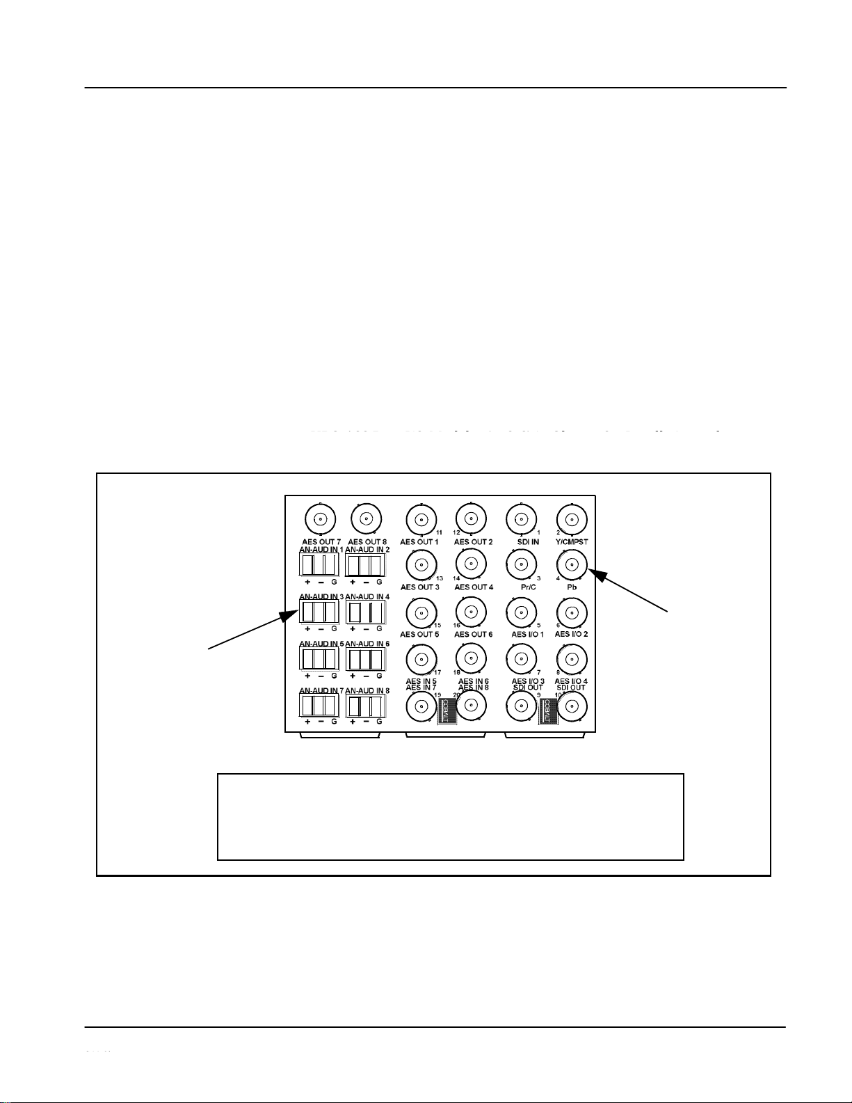
The UPC-166 physically interfaces to system video and audio connections
using a Rear I/O Module. Figure 1-10 shows a typical UPC-166 Rear I/O
Module.
All inputs and outputs shown in the UPC-166 Functional Block Diagram
(Figure 1-1) enter and exit the card via the card edge backplane connector.
The Rear I/O Module breaks out the UPC-166 card edge connections to
industry standard connections that interface with other components and
systems in the signal chain.
In this manner, the particular inputs and outputs required for a particular
application can be accommodated using a Rear I/O Module that suits the
requirements. The required input and outputs are broken out to the industry
standard connectors on the Rear I/O Module; the unused inputs and outputs
remain unterminated and not available for use.
The full assortment of UPC-166 Rear I/O Modules is shown and
described in
connectors for balanced
Figure 1-10 Typical UPC-166 Rear I/O
1-21
UPC-166-OM
BNC connectors for coaxial
video and AES audio signals
3-wire Phoenix terminal block
analog audio signals
UPC-166GA.PNG
In this example, an RM-UPC-166-G Rear I/O Module provides a connection interface for
the signal types shown here.
Rear I/O Modules RM-UPC-166-A through RM-UPC-166-F offer other options particularly
suited to various requirements.
• • •
• • •
•
• •
•
• •
• • • • • •
•
• •
•
•
•
Page 26
1
UPC-166 Functional Description
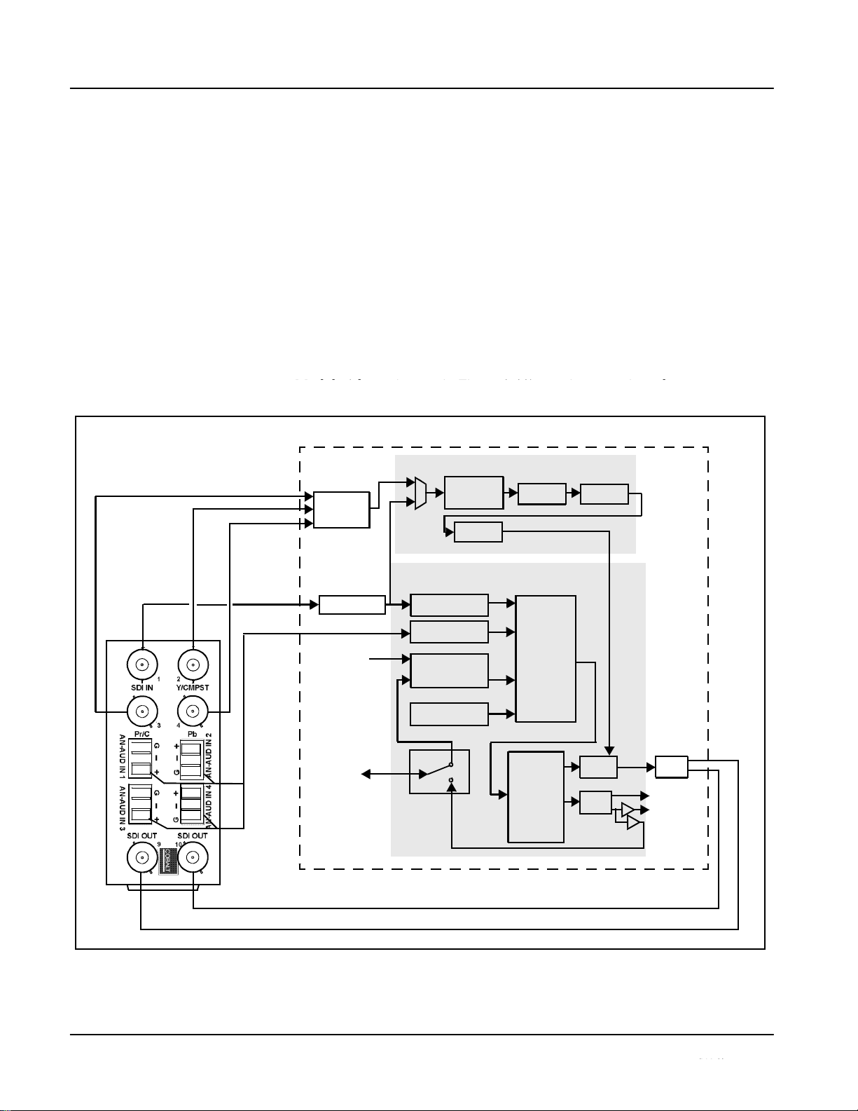
Figure 1-11 shows a UPC-166 card using a UPC-166-B Rear I/O Module.
Using this Rear I/O Module, this module provides industry standard breakout connections for the following inputs and outputs required by this
application:
• Inputs:
• SD SDI IN – SD-SDI input
• Y/Cmpst IN, Pr/C IN, Pb IN – analog composite/component video
inputs
• AN-AUD IN (1-4) – balanced analog audio inputs (inputs 5-8 unused)
• Outputs:
• SDI OUT – HD/SD-SDI buffered video outputs
The other UPC-166 inputs and outputs not accommodated by this
Rear I/O
Figure 1-11 UPC-166 with UPC-166-B Rear I/O
1-22
UPC-166-OM
UT
V ideo Processor
UPC-
166
Y/Cmpst IN
Pb IN
A
udio Processor
SD-SDI IN
AN-AUD
IN (1-4)
AES IN (5-8)
AES
I/O
(1-4)
SDI O
AES OUT
(5-8)
(1-4)
Page 27
Introduction
UPC-166 Functional Description
Audio and Video Formats Supported by the UPC-
The UPC-166 supports all current SMPTE-standard SD video input formats
and HD/SD video output formats. Table 1-2 lists and provides details
regarding the audio and video formats supported by the UPC-166.
Table 1-2
Supported Audio and Video Formats
1-23
UPC-166-OM
Item
Description/Specification
Input Video
Raster Structure:
Frame Rate:
486i
(1)
29.97
575i
(1)
25
Output Video
Raster Structure:
Frame Rate:
1080PsF
23.98; 24
1080p
23.98; 24
1080i
(1)
25; 29.97; 30
720p
23.98; 24; 25; 29.97; 30; 50; 59.94;
60
486i
(1)
29.97
575i
(1)
25
Embedded Audio
The UPC-166 supports all four groups (16 channels) of embedded
audio at full 24-bit resolution in both SD (with extended data packets)
and HD
Analog Audio
The UPC-166 supports 8 channels of balanced (differential) analog
audio. The analog audio is encoded such that a +24 dBu input is
equivalent to digital 0 dBFS.
Discrete AES Audio Input
The UPC-166 can accept 16 channels (8 pairs) of discrete AES audio
on 75Ω BNC connections. Sample rate conversion can be employed to
account for minor clock rate differences in the AES stream and the
input video stream.
Note: The AES signal must have a nominal rate of approximately
48 kHz. The UPC-166 does not support AES input at 32 kHz,
44.1 kHz, 96 kHz or 192 kHz rates.
Discrete AES Audio Output
The UPC-166 can provide 16 channels (8 pairs) of discrete AES audio
on 75Ω BNC connections.
(1) All rates displayed as frame rates; interlaced (―i‖) field rates are two times the rate value shown.
Page 28

1
Technical Specifications
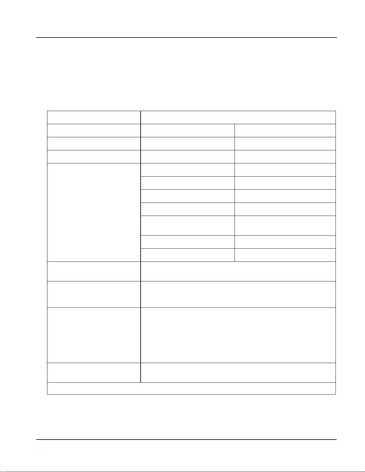
Technical Specifications
Table 1-3 lists the technical specifications for the UPC-166 Upconverter
with Analog/SDI Input, Audio Embed/De-Embed, Frame Sync,
Timecode and Closed Caption Support card.
Table 1-3
Technical Specifications
1-24
UPC-166-OM
Item
Characteristic
Part number, nomenclature
UPC-166 Upconverter with Analog/SDI Input, Audio Embed/
De-Embed, Frame Sync, Timecode and Closed Caption Support
Installation/usage environment
Intended for installation and usage in frame meeting openGear™
modular system definition.
Power consumption
< 24 Watts maximum
Environmental:
Operating temperature:
Relative humidity (operating or storage):
32° – 104° F (0° – 40° C)
< 95%, non-condensing
Frame communication
10/100 Mbps Ethernet with Auto-MDIX.
Indicators
Card edge display and indicators as follows:
• 4-character alphanumeric display
• Status/Error LED indicator
• Input Format LED indicator
Controls
Card edge switches as follows:
• Menu Enter pushbutton switch
• Menu Exit pushbutton switch
• Up/down selection toggle switch
Internal Tone Generators
Four built-in tone generators, each configurable for 18 discrete
sine wave frequencies ranging from 50 Hz to 16 kHz.
Generator source signal level is equivalent to -20 dBu.
A/D Process
8:8:8
Resolution:
12-bit A/D and 10-bit video data path
SD Comb Filter:
5-line adaptive
Page 29

Introduction
Technical Specifications
Table 1-3
Technical Specifications — continued
1-25
UPC-166-OM
Item
Characteristic
Serial Digital Video Input
Data Rates Supported:
SMPTE 259M-C SD-SDI: 270 Mbps
Impedance:
75 Ω terminating
Equalization:
1000 ft (305 m) Belden 1694A
Return Loss:
> 15 dB at 5 MHz – 1.485 GHz
Analog Video Input
Input Complement:
Separate component Y/composite, Pr/C, and Pb inputs
Input Type:
Differential; Common Mode Rejection = 5 VAC
Video Input Types:
Composite, Component YPbPr (BetaCam™, MII™,
SMPTE/N10)
Conversion Bit Depth:
12 bits
SD Color Separation:
5-Line Adaptive Comb or Notch Filter
Frequency Response:
0 – 5.2 MHz ± 0.25dB
Differential Phase:
< ± 0.4° typical
Differential Gain:
< ± 0.4% typical
Analog Front-End Crosstalk:
Within noise floor measurement
Return Loss:
> 20 dB to 30 MHz
Serial Digital Video Outputs
Number of Outputs:
Two HD/SD-SDI BNC per IEC 60169-8 Amendment 2
Impedance:
75 Ω
Page 30

1
Technical Specifications
Table 1-3
Technical Specifications — continued
1-26
UPC-166-OM
Item
Characteristic
Serial Digital Video Outputs (cont.)
Return Loss:
> 15 dB at 5 MHz – 270 MHz
> 12 dB at 270 MHz – 1.485 GHz
Signal Level:
800 mV ± 10%
DC Offset:
0 V ± 50 mV
Jitter (HD):
< 0.15 UI (all outputs)
Jitter (SD):
< 0.10 UI (all outputs)
Overshoot:
< 0.2% of amplitude
AES Audio Input
Standard:
SMPTE 276M
Number of Inputs (maximum):
8 unbalanced
Input Level:
0.1 to 2.5 Vp-p (5 Vp-p tolerant)
Input Impedance:
75 Ω
Return Loss:
> 12 dB at 100 kHz to 6 MHz
Resolution:
24-bit only
Sample Rate:
48 kHz
SRC:
32-channel; 142 dB S/N
AES Audio Output
Standard:
SMPTE 276M
Number of Outputs (maximum):
8 unbalanced
Page 31

Introduction
Technical Specifications
Table 1-3
Technical Specifications — continued
1-27
UPC-166-OM
Item
Characteristic
AES Audio Output (cont.)
Output Impedance:
75 Ω
Return Loss:
> 30 dB at 100 kHz to 6 MHz
Sample Rate:
48 kHz
Analog Audio Input
Number of Inputs (maximum):
Eight, 3-wire balanced analog audio using Phoenix connectors
with removable screw terminal blocks (Phoenix PN 1803581;
Cobalt PN 5000-0013-000R)
Sampling Rate:
48 kHz (locked to video input)
Signal Level:
+24 dBu => 0 dBFS
A/D Frequency Response:
20 – 20 kHz ± 0.25 dB
Dolby® RS485 Metadata Output
Metadata extracted from input video (per SMPTE 2020-1-2008) on
RS-485 interface; 3-wire balanced via Phoenix terminal block
connector.
Reference Video Input
Number of Inputs:
Two non-terminating (looping) Frame Reference inputs
Standards Supported (HD):
720p 24; 25; 29.97; 30; 50; 59.94
1080i 25; 29.97
1080p 23.98; 24; 25; 29.97; 30
1080p/sF 23.98; 24
Standards Supported (SD):
486i 29.97 (NTSC)
575i 25 (PAL)
Signal Level:
1 Vp-p nominal
Signal Type:
Analog video sync (black burst or tri-level)
Impedance:
75 Ω
Return Loss:
> 30 dB to 30 MHz
Allowable Maximum DC on Ref Input:
±1.0 V
Page 32

1
Warranty and Service Information
Warranty and Service Information
Sierra Video Limited Warranty
This product is warranted to be free from defects in material and workmanship for a period of five (5)
years from the date of shipment to the original purchaser, except that 4000, 5000, 6000, 8000 series
power supplies, and Dolby® modules (where applicable) are warranted to be free from defects in
material and workmanship for a period of one (1) year.
Sierra Video's sole obligation under this warranty shall be limited to, at its option, (i) the repair or
(ii) replacement of the product, and the determination of whether a defect is covered under this limited
warranty shall be made at the sole discretion of Sierra Video.
This limited warranty applies only to the original end-purchaser of the product, and is not assignable or
transferrable therefrom. This warranty is limited to defects in material and workmanship, and shall not
apply to acts of God, accidents, or negligence on behalf of the purchaser, and shall be voided upon the
misuse, abuse, alteration, or modification of the product. Only Sierra Video authorized factory
representatives are authorized to make repairs to the product, and any unauthorized attempt to repair
this product shall immediately void the warranty. Please contact Sierra Video Technical Support for
more information.
To facilitate the resolution of warranty related issues, Sierra Video recommends registering the
product by completing and returning a product registration form. In the event of a warrantable defect,
the purchaser shall notify Sierra Video with a description of the problem, and Sierra Video shall
provide the purchaser with a Return Material Authorization (“RMA”). For return, defective products
should be double boxed, and sufficiently protected, in the original packaging, or equivalent, and
shipped to the Sierra Video Factory Service Center, postage prepaid and insured for the purchase
price. The purchaser should include the RMA number, description of the problem encountered, date
purchased, name of dealer
purchased from,
and serial number with the shipment.
Sierra Video Factory Service Center
PO. Box 2462
Grass Valley, CA 95945
USA
Office: (530) 478-1000
Fax:
(530) 478-1105
Email: info@sierravideo.com
THIS LIMITED WARRANTY IS EXPRESSLY IN LIEU OF ALL OTHER WARRANTIES
EXPRESSED OR IMPLIED, INCLUDING THE WARRANTIES OF MERCHANTABILITY AND
FITNESS FOR A PARTICULAR PURPOSE AND OF ALL OTHER OBLIGATIONS OR
LIABILITIES ON SIERRA VIDEO'S PART. ANY SOFTWARE PROVIDED WITH, OR FOR USE
WITH, THE PRODUCT IS PROVIDED “AS IS.” THE BUYER OF THE PRODUCT
ACKNOWLEDGES THAT NO OTHER REPRESENTATIONS WERE MADE OR RELIED UPON
WITH RESPECT TO THE QUALITY AND FUNCTION OF THE GOODS HEREIN SOLD.
SIERRA VIDEO PRODUCTS ARE NOT AUTHORIZED FOR USE IN LIFE SUPPORT
APPLICATIONS.
SIERRA VIDEO'S LIABILITY, WHETHER IN CONTRACT, TORT, WARRANTY, OR
OTHERWISE, IS LIMITED TO THE REPAIR OR REPLACEMENT, AT ITS OPTION, OF ANY
DEFECTIVE PRODUCT, AND SHALL IN NO EVENT INCLUDE SPECIAL, INDIRECT,
INCIDENTAL, OR CONSEQUENTIAL DAMAGES (INCLUDING LOST PROFITS), EVEN IF IT
HAS BEEN ADVISED OF THE POSSIBILITY OF SUCH DAMAGES.
1-28
UPC-166-OM
Page 33

Introduction
Contact Sierra Video
Contact Sierra Video.
Feel free to contact our friendly and professional support representatives for
any of the following:
Name and address of your local dealer
Product information and pricing
Technical support
Upcoming trade show information
•
•
•
•
1-29
UPC-166-OM
Phone:
(530) 478-100
Fax:
(530) 478-1105
Web:
www.sierravideo.com
General Information:
info@sierravideo.com
Technical Support:
support@sierravideo.com
Page 34

This page intentionally blank
1-30
UPC-166-OM
Page 35

Chapter 2
Installation and Setup
Overview
This chapter contains the following information:
• Setting I/O Switches for AES I/O (1-4) Ports (p. 2-1)
• Installing the UPC-166 Into a Frame Slot (p. 2-2)
• Installing a Rear I/O Module (p. 2-4)
• Setting Up UPC-166 Network Remote Control (p. 2-9)
Setting I/O Switches for AES I/O (1-4) Ports
Note:
This procedure is applicable only if any of the four AES I/O (1-4) ports on the
UPC-166 are to be used as outputs (the switches are set to input mode by
factory default). The UPC-166 is equipped with a four-section red DIP switch
that sets AES pairs 1 thru 4 as either inputs or outputs. The factory default
position is the input position for each pair.
• If all of the AES I/O (1-4) ports are to be used as inputs (or not used at all),
omit this procedure.
• If any of the AES I/O (1-4) ports are to be used as outputs, set the switches
as described in this procedure.
Note switch S11 thru S14 settings for AES I/O 1 thru AES I/O 4 mode shown
in Figure 2-1. For port to be used as an output, set switch to down position as
shown in Figure 2-1.
Note:
Regardless of S11 thru S14 settings for AES I/O 1 thru AES I/O 4, outputs
AES OUT (1-8) are still available on cards equipped with a Rear I/O Module
having dedicated AES OUT (1-8) BNC connectors.
2-1
UPC-166-OM
Page 36

2
Installing the UPC-166 Into a Frame
Figure 2-1 UPC-166 AES I/O (1-4) Mode
Installing the UPC-166 Into a Frame
Heat and power distribution requirements within a frame may dictate specific
slot placement of cards. Cards with many heat-producing components should
be arranged to avoid areas of excess heat build-up, particularly in frames
using only convection cooling. The UPC-166 has a moderate power
dissipation (24 W max.). As such, avoiding placing the card adjacent to other
cards with similar dissipation values if possible.
2-2
UPC-166-OM
This device contains semiconductor devices which are
susceptible to serious damage from Electrostatic
Discharge (ESD). ESD damage may not be immediately
apparent and can affect the long-term reliability of the
device.
Avoid handling circuit boards in high static environments
such as carpeted areas, and when wearing synthetic fiber
clothing. Always use proper ESD handling precautions
and equipment when working on circuit boards and
related equipment.
CAUTION
CAUTION
Rear of Card
AES I/O 4
AES
I/O
AES I/O
AES I/O
S11 S12 S13 S14
INPUT MODE
(Factory Default)
OUTPUT MODE
•
• • •
3
2
1
Page 37

Installation and Setup
Installing the UPC-166 Into a Frame
Note:
• If installing the UPC-166 in an 8310-C-BNC or 8310-BNC frame (which
is pre-equipped with a 100-BNC rear I/O module installed across the entire
backplane) or a slot already equipped with a suitable I/O module, proceed to
card installation steps below.
/O
Module is required before cabling can be connected. Refer to
If required, make certain Rear I/O Module(s) is installed before installing the
UPC-166 into the frame slot. Damage to card and/or Rear I/O Module can
occur if module installation is attempted with card already installed in slot.
Note:
Check the packaging in which the UPC-166 was shipped for any extra items
such as a Rear I/O Module connection label. In some cases, this label is
shipped with the card and to be installed on the Rear I/O connector bank
correspond- ing to the slot location of the card.
Install the UPC-166 into a frame slot as
1. Determine the slot in which the UPC-166 is to be installed.
2. Open the frame front access panel.
3. While holding the card by the card edges, align the card such that the
plastic ejector tab is on the bottom.
4. Align the card with the top and bottom guides of the slot in which the
card is being installed.
5. Gradually slide the card into the slot. When resistance is noticed, gently
continue pushing the card until its rear printed circuit edge terminals
engage fully into the rear I/O module mating connector.
If card resists fully engaging in rear I/O module mating connector, check for
alignment and proper insertion in slot tracks. Damage to card and/or rear I/O
module may occur if improper card insertion is attempted.
6. Verify that the card is fully engaged in rear I/O module mating connector.
7. Close the frame front access panel.
2-3
UPC-166-OM
CAUTION
CAUTION
Page 38

2
Installing a Rear I/O Module
8. Connect the input and output cables as follows:
• If the UPC-166 is being installed in a PN 8310-BNC or 8310-C-
BNC frame, refer to the label on the connector bank corresponding
to the card’s slot location for connector designations.
• If the UPC-166 is being installed in a PN 8310-C frame using a UPC-
166 Rear I/O Module (PN RM-UPC-166-A thru RM-UPC-166-G),
connect cabling in accordance with the appropriate diagram shown in
Table 2-1, “UPC-166 Rear I/O Modules” (p. 2-6).
9. Repeat steps 1 through 8 for other UPC-166 cards.
Note:
The UPC-166 BNC inputs are internally 75-ohm terminated. It is not
necessary to terminate unused BNC inputs or outputs.
Note:
To remove a card, press down on the ejector tab to unseat the card from the
rear I/O module mating connector. Evenly draw the card from its slot.
10. If network remote control is to be used for the frame and the frame has
not yet been set up for remote control, perform setup in accordance with
Setting Up UPC-166 Network Remote Control (p. 2-9).
Note:
If installing a card in a frame already equipped for, and connected to
DashBoard™, no network setup is required for the card. The card will be discovered by DashBoard™ and be ready for use.
Installing a Rear I/O Module
Note:
This procedure is applicable only if a Rear I/O Module is not currently
installed in the slot where the UPC-166 is to be installed.
If installing the UPC-166 in a 8310-C-BNC or 8310-BNC frame (which is
pre-equipped with a 100-BNC rear I/O module installed across the entire
backplane) or a slot already equipped with a suitable I/O module, omit this
procedure.
The full assortment of UPC-166 Rear I/O Modules is shown and
described in UPC-166 Rear I/O Modules (p. 2-6). Install a Rear I/O
Module as follows:
1. On the 8310 frame, determine the slot in which the UPC-166 is to be
installed.
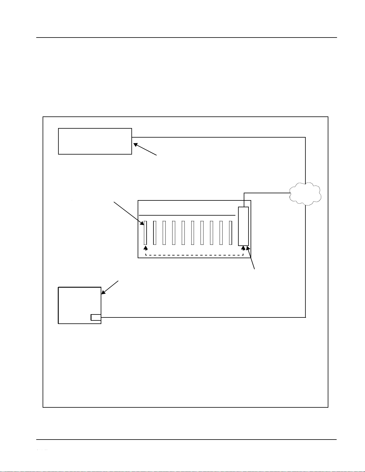
2. In the mounting area corresponding to the slot location, install
Rear I/O Module as shown in Figure 2-2.
2-4
UPC-166-OM
Page 39

Installation and Setup
Installing a Rear I/O Module
1 I/O Module with the module seating slot
Lightly tighten captive screw.
Figure 2-2
Rear I/O Module Installation
2-5
UPC-166-OM
Align and engage mounting tab on Rear
on rear of frame chassis.
DSCN3483A.JPG
Hold top of Rear I/O Module flush against
2
frame chassis and start the captive screw.
Note: Rear I/O Modules RM-UPC-166-C thru RM-UPC-166-F
occupy two rear module slot mounting locations and use
two captive screws.
Rear I/O Module RM-UPC-166-G occupies three rear
module slot mounting locations and uses three captive
screws.
DSCN3487A.JPG
Page 40

2
Installing a Rear I/O Module
UPC-166 Rear I/O
Table 2-1 shows and describes the full assortment of Rear I/O Modules
specifically for use with the UPC-166.
Note:
Rear I/O Modules equipped with 3-wire Phoenix connectors are supplied with
removable screw terminal block adapters. For clarity, the adapters are omitted in the drawings below.
Table 2-1
UPC-166 Rear I/O
2-6
UPC-166-OM
UPC-166 Rear I/O Module
Description
RM-UPC-166-A
UPC-
166A.PNG
Provides the following
connections:
• SD-SDI coaxial input (SDI IN)
• Analog Y/composite, Pr/C, and Pb coaxial inputs
(Y/Cmpst, Pr/C, and Pb, respectively)
• Four AES I/O coaxial input/outputs (AES I/O 1 thru
AES I/O 4; I/O function of each connection is
user-configurable)
• Two buffered SDI coaxial outputs (SDI OUT)
RM-UPC-166-B
UPC-
166B.PNG
Provides the following
connections:
• SD-SDI coaxial input (SDI IN)
• Analog Y/composite, Pr/C, and Pb coaxial inputs
(Y/Cmpst, Pr/C, and Pb, respectively)
• Four analog balanced audio inputs (AN-AUD IN 1
thru AN-AUD IN 4)
• Two buffered SDI coaxial outputs (SDI OUT)
•
•
•
•
•
•
•
•
•
Page 41

Installation and Setup
Installing a Rear I/O Module
Table 2-1
UPC-166 Rear I/O Modules —
2-7
UPC-166-OM
UPC-166 Rear I/O Module
Description
RM-UPC-166-C
UPC-166C.PNG
Provides the following
connections:
• SD-SDI coaxial input (SDI IN)
• Analog Y/composite, Pr/C, and Pb coaxial inputs
(Y/Cmpst, Pr/C, and Pb, respectively)
• Four AES I/O coaxial input/outputs (AES I/O 1 thru
AES I/O 4; I/O function of each connection is
user-configurable)
• Two dedicated AES coaxial audio inputs (AES IN 5
and AES IN 6)
• Eight analog balanced audio inputs (AN-AUD IN 1
thru AN-AUD IN 8)
• Two buffered SDI coaxial outputs (SDI OUT)
RM-UPC-166-D
UPC-166D.PNG
Provides the following
connections:
• SD-SDI coaxial input (SDI IN)
• Four AES I/O coaxial input/outputs (AES I/O 1 thru
AES I/O 4; I/O function of each connection is
user-configurable)
• Four dedicated AES coaxial audio inputs (AES IN 5
thru AES IN 8)
• Eight dedicated AES coaxial audio outputs
(AES OUT 1 thru AES OUT 8)
• Two buffered SDI coaxial outputs (SDI OUT)
Note: AES OUT 1 thru AES OUT 4 on RM-UPC-
166-D Rear I/O Module always function as
outputs regardless of whether AES I/O 1 thru
AES I/O 4 are used as inputs or
outputs.
Page 42

2
Installing a Rear I/O Module
Table 2-1
UPC-166 Rear I/O Modules —
2-8
UPC-166-OM
UPC-166 Rear I/O Module
Description
RM-UPC-166-E
UPC-166E.PNG
Provides the following
connections:
• SD-SDI coaxial input (SDI IN)
• Analog Y/composite, Pr/C, and Pb coaxial inputs
(Y/Cmpst, Pr/C, and Pb, respectively)
• Four AES I/O coaxial input/outputs (AES I/O 1 thru
AES I/O 4; I/O function of each connection is
user-configurable)
• Four dedicated AES coaxial audio inputs (AES IN 5
thru AES IN 8)
• Six dedicated AES coaxial audio outputs
(AES OUT 1 thru AES OUT 6)
• Two buffered SDI coaxial outputs (SDI OUT)
Note: AES OUT 1 thru AES OUT 4 on RM-UPC-
166-E Rear I/O Module always function as
outputs regardless of whether AES I/O 1 thru
AES I/O 4 are used as inputs or
outputs.
RM-UPC-166-F
UPC-166F.PNG
Provides the following
connections:
• SD-SDI coaxial input (SDI IN)
• Analog Y/composite, Pr/C, and Pb coaxial inputs
(Y/Cmpst, Pr/C, and Pb, respectively)
• Eight analog balanced audio inputs (AN-AUD IN 1
thru AN-AUD IN 8)
• Four AES I/O coaxial input/outputs (AES I/O 1 thru
AES I/O 4; I/O function of each connection is
user-configurable)
• Dolby® RS-485 metadata output (DOLBY META)
• Two buffered SDI coaxial outputs (SDI OUT)
+ - G
Page 43

Installation and Setup
Setting Up UPC-166 Network Remote
Table 2-1
UPC-166 Rear I/O Modules —
Setting Up UPC-166 Network Remote
Perform remote control setup in accordance with Cobalt® reference guide
“COMPASS™ Remote Control User Guide” (PN 9000RCS-RM).
Note:
• If network remote control is to be used for the frame and the frame has
not
yet been set up for remote control, Cobalt® reference guide COMPASS™
Remote Control User Guide (PN 9000RCS-RM) provides thorough information and step-by-step instructions for setting up network remote control of
COMPASS™ cards using DashBoard™. (Cobalt® OGCP-9000 and
OGCP-9000/CC Remote Control Panel product manuals have complete
instructions for setting up remote control using a Remote Control Panel.)
Download a copy of this guide by clicking on the Support>Downloads link
at
www.cobaltdigital.com
and then select DashBoard Remote Control Setup
Guide as a download, or contact Cobalt® as listed in Contact Sierra Video.
(p. 1-29).
• If installing a card in a frame already equipped for, and connected to
DashBoard™, no network setup is required for the card. The card will be discovered by DashBoard™ and be ready for use.
2-9
UPC-166-OM
UPC-166 Rear I/O Module
Description
RM-UPC-166-G
UPC-166GA.PNG
Provides the following
connections:
• SD-SDI coaxial input (SDI IN)
• Analog Y/composite, Pr/C, and Pb coaxial inputs
(Y/Cmpst, Pr/C, and Pb, respectively)
• Four dedicated AES coaxial audio inputs
(AES IN 5 thru AES IN 8)
• Eight dedicated AES coaxial audio outputs
(AES OUT 1 thru AES OUT 8)
• Four AES I/O coaxial input/outputs (AES I/O 1 thru
AES I/O 4; I/O function of each connection is
user-configurable)
• Eight analog balanced audio inputs (AN-AUD IN 1
thru AN-AUD IN 8)
• Two buffered SDI coaxial outputs (SDI OUT)
Note: AES OUT 1 thru AES OUT 4 on RM-UPC-
166-G Rear I/O Module always function as
outputs regardless of whether AES I/O 1 thru
AES I/O 4 are used as inputs or
outputs.
Page 44

This page intentionally blank
2-10
UPC-166-OM
Page 45

Chapter 3
Operating Instructions
Overview
This chapter contains the following information:
• Control and Display Descriptions (p. 3-1)
• Accessing the UPC-166 Card via Remote Control (p. 3-12)
• Checking UPC-166 Card Information (p. 3-14)
• Ancillary Data Line Number Locations and Ranges (p. 3-15)
• UPC-166 Function Submenu List and Descriptions (p. 3-16)
• Troubleshooting (p. 3-70)
Control and Display Descriptions
This section describes the user interface controls, indicators, and displays
(both on-card and remote controls) for using the UPC-166 card. The
UPC-166 functions can be accessed and controlled using any of the user
interfaces described here.
The format in which the UPC-166 functional controls, indicators, and
displays appear and are used varies depending on the user interface being
used. Regardless of the user interface being used, access to the UPC-166
functions (and the controls, indicators, and displays related to a particular
function) follows a general arrangement of Function Submenus under which
related parameters can be accessed (as described in Function
Submenu/Parameter Submenu Overview below).
After familiarizing yourself with the arrangement described in Function
Submenu/Parameter Submenu Overview, proceed to the subsection for the
particular user interface being used. Descriptions and general instructions for
using each of the three user interfaces are individually described in the
following subsections:
• UPC-166 Card Edge Controls, Indicators, and Display (p. 3-3)
• DashBoard™ User Interface (p. 3-8)
• Cobalt
®
Remote Control Panel User Interfaces (p. 3-11)
3-1
UPC-166-OM
Page 46

3
Control and Display Descriptions
Note:
Instructions provided here are applicable for all available user control methods. However, DashBoard™ and the Remote Control Panel provide greatly
simplified user interfaces as compared to using the card edge controls. For
this reason, it is strongly recommended that DashBoard™ or a Remote
Control Panel be used for all card applications other than the most basic
cases.
Not all functions available using DashBoard™ or the Control Panel are available using the card edge controls.
When a setting is changed, settings displayed on DashBoard™ (or the
Remote Control Panel) are the settings as effected by the UPC-166 card itself
and reported back to the remote control; the value displayed at any time is
the actual value as set on the card.
Note:
Note:
Function Submenu/Parameter Submenu Overview
The functions and related parameters available on the UPC-166 card are
organized into function submenus, which consist of parameter groups as
shown below.
Figure 3-1 shows how the UPC-166 card and its submenus are organized, and
also provides an overview of how navigation is performed between cards,
function submenus, and parameters.
Figure 3-1 Function Submenu/Parameter Submenu Overview
3-2
UPC-166-OM
If using DashBoard™ or a Remote Control Panel, the
desired UPC-166 card is first selected.
The desired function submenu is next
selected.
Function Submenus consist of parameter
groups related to a particular UPC-166
card function (for example, ―Video Proc‖).
• • •
Individual
Parameters
Each submenu consists of groups of parameters
related to the function submenu. Using the ―Video
Proc‖ function submenu example, the individual
parameters for th is function consist of various video
processor parameters such as Luma Gain, Saturation,
and so on.
Submenu z
Submenu b
Submenu a
UPC-166
Page 47

Operating Instructions
Control and Display Descriptions
UPC-166 Card Edge Controls, Indicators, and
Figure 3-2 shows and describes the UPC-166 card edge controls, indicators,
and display.
Enter Submenu Pushbutton
Figure 3-2 UPC-166 Controls, Indicators, and
3-3
UPC-166-OM
UPC-
RMT
REF
ERR
625
525
4-Character Alphanumeric Display
Menu Selection
Toggle Switch
MENU DEPTH
Exit Submenu Pushbutton
Status
Input Format
Menu Depth
Indicators
Indicators
Indicators
Item
Function
Display
Displays 4-digit abbreviated code showing menu and submenu selections. When in a menu displaying a
parameter setting, the display shows parametric scalar value (and +/- sign where applicable).
Menu
Selection
toggle switch
• When in a menu or submenu selection mode, moving the switch up or down toggles up and down through the
menu or submenu item choices.
• When in a mode where parameter setting is displayed, moving the switch up or down increase or decreases
the parametric value.
Enter Menu
Pushbutton
When pressed, selects and opens the current mode shown on the display. At this point, submenu choices within
the selected menu are now displayed. Pressing the pushbutton again goes deeper into the submenu, now
opening items subordinate to the selected submenu. In this manner, pressing the Enter Menu pushbutton
navigates into a menu and its submenus.
Exit Menu
Pushbutton
When pressed, moves in the opposite direction of the Enter Menu pushbutton. It closes the currently selected
submenu and moves to the next higher menu, eventually moving completely out of the item’s submenus. In this
manner, pressing the Exit Menu pushbutton navigates out of a menu and its submenus.
Input Format
Indicators
Two blue LEDs indicate the input signal raster format being received and locked onto by the UPC-166 (525,
625). Continuous cycling of the LEDs indicates the UPC-166 has not locked onto a particular format (as in the
case of no signal input).
Menu Depth
Indicators
Four green LEDs show the currently selected menu/submenu depth navigation.
• No LEDs indicate top-level menu items are now ready for selection.
• One LED indicates first submenu items (items
subordinate
to currently selected menu item) are now ready for
selection.
• Two LEDs indicates second submenu items (items subordinate to currently selected submenu item) are now
ready for selection.
• Three LEDs indicates third submenu items (items subordinate to currently selected submenu item) are now
ready for selection. Typically, this is the level where values can now be adjusted for a specific parameter.
• Four LEDs indicate fourth submenu items are now ready for selection. (This depth is not applicable to most
items.)
RMT LED
Blue LED flashes when UPC-166 is receiving control message from remote network control (e.g., DashBoard™
or Remote Control Panel).
REF LED
Blue LED illuminates when UPC-166 is receiving valid framesync when set up for framesync reference.
ERR LED
Red LED illuminates when UPC-166 unable to lock to framesync, or unable to lock to input standard.
Page 48

3
Control and Display Descriptions
UPC-166 Card Edge Control Menu/Submenu Structure
(See below.) Using the menu system of group menus and submenus described
earlier, the UPC-166
parameters/controls
are organized into menus and
submenus. As appropriate, a submenu similarly may have its own further
additional subordinate submenus.
1
(Submen u 1 selection items)
2
(Submenu 2 selection items)
3
(Submenu 3 selection
4
(Submenu 4 selection
Figure 3-3 shows an example of using the card edge controls to access the
Embedded Audio processing group menu (along with some of its submenus)
to set the routing and signal processing parameters for an embedded audio
channel.
through
in Figure 3-3 denote the discrete tasks required in
A
S
performing the example setup using the UPC-166 card edge controls.
In this example, the following input processing is being performed:
• Embedded Channel 3 is selected as the source for Embedded
Channel 1 within Embedded Audio Group 1.
• Gain is increased over unity default by 12.1.
• Phase is inverted.
In this example, the following output processing is being performed:
• The embedded Channel 1 path has been directed to AES Output
Channel 1.
• Gain is increased over unity output default by 18.5.
• Phase is normal (non-inverted).
Due to the limited control available when using the built-in card edge
control user interface, the navigation into and out of submenus shown in
Figure 3-3 is required to perform the setup described above.
3-4
UPC-166-OM
Menu depth (as indicated by
Menu Depth UPC-166 Menu Depth LEDs)
Menu Group Item
none
Submenu 1
Submenu 2
Submenu 3
items and/or parameter
values)
Submenu 4
items and/or
parameter values)
Page 49

Operating Instructions
Control and Display Descriptions
Embedded Audio
(embedded audio routing/control))
Inv
Figure 3-3 Card Edge Controls Setup of Example Embedded Audio Function (sheet 1 of 2)
3-5
UPC-166-OM
Select a top-level menu item (in this example, select Aud
Submenu Depth
Audio Groups). This selects embedded audio function of the
group to be
accessed.
(Enable).
sets the selected embedded audio group to Enabled.
Embedded
Channel
1). This selects the embedded channel to be
embedded channel 1). This selects the source for the embedded
(embeddded channel 3 as source for embedded channel 1). This
channel 1.
adjustment field for selected embedded audio channel).
of 12.1 for this channel.
embedded channel 1).
polarity for embedded channel 1).
(continued on next page)
A
1
Embd
AES
Tone
2 3
4
Press
Enter
Menu
and
in this
example,
select Embd (Embedded
Audio processor.
B
Grp1
Grp2
Grp3
Grp4
Press Enter Menu again and in this example, select Grp1
(Embedded Audio Group 1). This selects the embedded audio
C
Enbl
Press Enter Menu again and in this example, select Enbl
D
On
Off
Press Enter Menu again and in this example, select On. This
E
Ch01
Ch02
Ch03
Ch04
Press Exit Menu and in this example, select Ch01 (Destination:
accessed.
F
Src
Gain
Pol
Press Enter Menu and select in this example, Src (source for
channel.
G
Em01
Em02
Em03
...
Press Enter Menu again and in this example, select Em03
selects embedded channel 3 as the source for embedded
H
Src
Gain
Pol
Press Exit Menu and in this example, select Gain (gain
I
(gain
value)
Press Enter Menu again and in this example, select a gain value
J
Src
Gain
Pol
Press Exit Menu and in this example, select Pol (phase for
K
Norm
Press Enter Menu again and in this example, select Inv (invert
Page 50

3
Control and Display Descriptions
Figure 3-3 Card Edge Controls Setup of Example Embedded Audio Function (sheet 2 of 2)
3-6
UPC-166-OM
Submenu Depth
channel selection). This selects an AES output channel as the
Channel
1).
for AES Output Channel 1).
(Embeddded Channel 1 as source for AES Output Channel 1).
adjustment field for selected AES output channel).
18.5 for this channel.
Embedded Channel 1).
AES output channel 1).
In Table 3-2, ―UPC-166
Function
Submenu List‖
Card Edge Control Menu:
navigation required to access a particular
Card Edge Setup Abbreviated Diagram
abbreviated diagrams
(as
shown above
and
Aud
in the example to the right) show the
submenu
item or
parameter
when using the
card edge controls.
Set embedded audio group to On
Set embedded audio group to Off
In this example, group enable for
Embedded Audio Group 1 is being enabled.
1
Embd
2
Grp1
3
Enbl
4
On
Off
L
1
Embd
AES
Tone
2 3
4
(continued from previous page)
Go to submenu 1 and in this example, select AES (AES output
output for this group.
M
Ch01
Ch02
Ch03
...
Press
Enter
Menu
and
in this
example,
select Ch01 (AES Output
N
Src
Gain
Pol
Press Enter Menu again and select in this example, Src (source
O
Em01
Em02
Em03
...
Press Enter Menu again and in this example, select Em01
P
Src
Gain
Pol
Press Exit Menu and in this example, select Gain (gain
Q
(gain
value)
Press Enter Menu and in this example, select a gain value of
R
Src
Gain
Pol
Press Exit Menu and in this example, select Pol (polarity for
S
Norm
Inv
Press
Enter Menu
and in this
example, select
Norm (no
invert
for
Page 51

Operating Instructions
Control and Display Descriptions
Card Edge Display Orientation, Brightness, and Timeout
Adjust
The card edge 4-Character Alphanumeric Display can be changed between
vertical or horizontal character orientation to suit the mounting position of the
card as shown and described below.
Figure 3-4 Card Edge Display Orientation
1. Access the Displ (Display) menu.
2. Select between Horizontal or Vertical as shown below.
Adjust the display brightness as described below.
1. Access the Displ (Display) menu.
2. Select from the relative brightness levels as shown below.
3-7
UPC-166-OM
UPC-
Card Edge Control Menu:
Disp
1
BRGT
2
100%
53%
40%
27%
20%
13%
6.6%
Card Edge Control Menu:
Disp
Horizontal orientation
Vertical orientation
1
H/V
2
Horz
Vert
Vertical orientation displays characters as
Horizontal orientation displays characters
shown above (in this example, ―Disp‖). Use
as shown above (in this example, ―Disp‖).
this orientation when a frame has cards
Use this orientation when a frame has cards
positioned vertically.
positioned horizontally.
UPC-
D
p
s i
D
p
s i
Page 52

3
Control and Display Descriptions
The timeout period from when a menu is entered to when the display times
outs (reverts to the default card model display) can be adjusted from 5 to 9999
seconds (166.7 minutes) as described below.
1. Access the Displ (Display) menu.
2. Use the up/down switch to enter the desired timeout value as shown
below.
DashBoard™ User Interface
(See Figure 3-5.) The UPC-166 function submenus are organized in
DashBoard™ using tabs (for example, “Embedded Audio Group 1/2” in
Figure 3-5). When a tab is selected, each parametric control or selection list
item associated with the function is displayed. Scalar (numeric) parametric
values can then be adjusted as desired using the GUI slider controls. Items in
a list can then be selected using GUI drop-down lists. (In this manner, the
setting effected using controls and selection lists displayed in DashBoard™
are comparable to the submenu items accessed and committed using the
UPC-166 card edge controls.)
Figure 3-5 shows the same setup described in Figure 3-3 as performed using
DashBoard™. Note how this setup is greatly simplified using DashBoard™
with most of the discrete tasks (
A
through S in Figure 3-3) performed
with the card edge controls now rolled into simple actions using
DashBoard™.
3-8
UPC-166-OM
Card Edge Control Menu:
Disp
Timeout value (in seconds)
1
TOUT
2
(value)
Page 53

Operating Instructions
Control and Display Descriptions
Figure 3-5
DashBoard™ Setup of Example Embedded Audio Function (sheet 1 of 2)
3-9
UPC-166-OM
Select top-level menu item Embedded
Audio Group 1
[ A – B in Figure
3-3]
Set Enable to On
[ C – D in Figure 3-3]
Select Embedded
Ch 1 Source as
Embedded Ch 3
[ E – G in Figure
3-3]
Set Gain for
Embedded Ch1 to
12.1 using direct
numeric entry or
slider control
[ H – I in Figure
3-3]
Set Phase for
Embedded Ch1 to
Invert
[ J – K in Figure
3-3]
AUDGRPEX1_V4.PNG
Page 54

3
Control and Display Descriptions
Figure 3-5
DashBoard™ Setup of Example Embedded Audio Function (sheet 2 of 2)
3-10
UPC-166-OM
Select Embedded Ch 1
as Source for AES Ch1
Select AES Audio
output
Out Pairs 1-4
[ N – O in Figure 3-3]
[ L – M in Figure 3-3]
Set Gain for AES Ch1
to 18.5 using direct
numeric
entry or slider
control
[ P – Q in Figure 3-3]
Set Phase for AES
Ch1 to Normal
[ R – S in Figure
3-3]
AUDGRPEX2_V4.PNG
Page 55

Operating Instructions
Control and Display Descriptions
Cobalt® Remote Control Panel User Interfaces
(See Figure 3-6.) Similar to the function submenu tabs using DashBoard™,
the Remote Control Panels have a Select Submenu key that is used to display
a list of function submenus. From this list, a control knob on the Control
Panel is used to select a function from the list of displayed function submenu
items.
When the desired function submenu is selected, each parametric control or
selection list item associated with the function is displayed. Scalar (numeric)
parametric values can then be adjusted as desired using the control knobs,
which act as potentiometers. Items in a list can then be selected using the
control knobs which correspondingly act as rotary switches. (In this manner,
the setting effected using controls and selection lists displayed on the Control
Panel are comparable to the submenu items accessed and committed using the
UPC-166 card edge controls.)
Figure 3-6 shows accessing a function submenu and its parameters (in this
example, “Video Proc”) using the Control Panel as compared to using the
card edge controls.
Note:
Refer to ―OGCP-9000 Remote Control Panel User Manual‖ (PN
OGCP-9000-OM) or ―OGCP-9000/CC Remote Control Panel User Manual‖
(PN OGCP-9000/CC-OM) for complete instructions on using the Control Panels.
key. Video Proc function is
function submenu is
parameters are now
Color Gain
Figure 3-6
Remote Control Panel Setup of Example Video Proc Function
3-11
UPC-166-OM
Video Proc function
(among others) is
accessed using the Control
Panel Select Submenu
selected from the list of
functions (submenu items)
3396B_3346BGEN2.JPG
When the Video Proc
selected, its related
displayed.
In this example, Color Gain
(saturation) is adjusted
using
the control knob adjacent to
3370_3372B.JPG
Card Edge Control Menu:
Vid
Color gain in percent
1
Proc
2
Sat
3
(sat
value)
Card Edge Control Menu:
Vid
Video Proc On
Video Proc Off
1
Proc
2
Enbl
3
On
Off
Page 56

3
Accessing the UPC-166 Card via Remote
Accessing the UPC-166 Card via Remote Control
Access the UPC-166 card using DashBoard™ or Remote Control Panels as
described below.
Accessing the UPC-166 Card Using
On the computer connected to the frame LAN, open DashBoard™.
As shown below (in the left side Basic View Tree) locate the Network
Controller Card associated with the frame containing the UPC-166 card
to be accessed (in this example, “MFC-8310-N SN: 00108053”).
1.
2.
As shown below, expand the tree to access the cards within the frame.
Click on the card to be accessed (in this example,
“Slot 7: CDI-UPC-166 RCVR21”).
3.
.
As shown on the next page, when the card is accessed a DashBoard™ its
function submenu screen showing tabs for each function is displayed.
(The particular submenu screen displayed is the previously displayed
screen from the last time the card was accessed by DashBoard™).
3-12
UPC-166-OM
UPC-166_DB_ACCESS2A.PNG
DB_ACCESS1.PNG
Page 57

Operating Instructions
Accessing the UPC-166 Card via Remote
Accessing the UPC-166 Card Using a Cobalt® Remote Control
Press the Select Device key and select a card as shown in the example below.
This display shows the list
is displayed with a reversed background (in this example,
is ready for selection
3-13
UPC-166-OM
3366_3392.JPG
This display shows the devices assigned to the Control Panel.
order number
of
the device
that
• Rotate any knob to select from the list of
devices.
The
device
selected using a
knob
―1 9066 - Receiver 21 Input Processing).
• Directly enter a device by entering its list number using the numeric keypad, and
then pressing Enter or pressing in any knob).
Card
Access/Navigation Card Info Card Function Submenu
Tree Pane Pane and Controls Pane
UPC-166_DB_ACCESS_V4.PNG
Page 58

3
Checking UPC-166 Card
Checking UPC-166 Card Information
The operating status and software version the UPC-166 card can be checked
using DashBoard™ or the card edge control user interface. Figure 3-7 shows
and describes the UPC-166 card information screen using DashBoard™ and
accessing card information using the card edge control user interface.
Note:
Proper operating status in DashBoard™ is denoted by green icons for the status indicators shown in Figure 3-7. Yellow or red icons respectively indicate
an alert or failure condition. Refer to Troubleshooting (p. 3-70) for corrective
action.
Checking Card Using
Figure 3-7
UPC-166 Card Info
3-14
UPC-166-OM
The Tree View shows the cards seen by DashBoard™.
In this example, Network Controller Card MFC-8310-N
(serial number ...8053) is hosting a UPC-166 card in
slot 7.
Software Version Number
Refer to these numbers to check that documentation (such as
this manual) matches the card’s Software Release Number
and Software Build Number. Use these numbers also when
co
Power Consumption and Temperature Displays
This display shows the power consumed by the UPC166 for both the +12V and -7.5V rails, as well as key
device temperatures.
Status Displays
These displays show the status the signal being received by
the UPC-166. Green Settings icon shows that any changes
made on DashBoard™ are sucessfully saved on the card’s
memory.
UPC-166_CARD_INFO.PNG
Info
Card Edge Controls
+12V Watts consumed
- 7.5V Watts consumed
Software Release Number
Software Build Number
FPGA Build Number
1
+POW
-POW
SWR#
SWB#
FPG#
2
(value)
(value)
(value)
(value)
(value)
regarding this card.
Page 59

Operating Instructions
Ancillary Data Line Number Locations and Ranges
Ancillary Data Line Number Locations and Ranges
Table 3-1 lists typical default output video VANC line number locations for
various ancillary data items that may be passed or handled by the card.
Table 3-1
Typical Ancillary Data Line Number Locations/Ranges
Because line number allocation is not standardized for all ancillary items,
consideration should be given to all items when performing set-ups. Figure
3-8 shows an example of improper and corrected VANC allocation within an
SDI stream.
Conflict between
ATC_VITC = 9/8
attempted using
on VANC line 9
(default)
CC = 10
CC = 10
VANC line 18
ATC_VITC on line 9/8
and
Dolby Metadata = 13
CC = 10
resolved
Figure 3-8 Example VANC Line Number Allocation Example
3-15
UPC-166-OM
AFD Insertion
ATC_VITC = 9/8
VANC line 9
AFD = 9
ATC_VITC and AFD both
Dolby Metadata = 13
Dolby Metadata = 13
AFD Insertion
ATC_VITC = 9/8
ATC_VITC = 9/8
corrected to use
CC = 10
Conflict
between
Dolby Metadata = 13
AFD = 18
AFD (now on line 18)
Card n
Card 1
Card n
Card 1
Item
Default Line No. /
Range
SD HD
AFD
12 (Note 2)
9 (Note 2)
ATC_VITC
12 (locked)
9/8 (Note 2)
ATC_LTC — 10 (Note 2)
Dolby® Metadata
13 (Note 2)
13 (Note 2)
SDI VITC Waveform
14/16 (Note 2)
—
Closed Captioning
21 (locked)
10 (Note 2)
Notes:
1. The card does not check for conflicts on a given line number. Make certain the selected line is available
and carrying no other data.
2. While range indicated by drop-down list on GUI may allow a particular range of choices, the actual range
is automatically clamped (limited) to certain ranges to prevent inadvertent conflict with active picture area
depending on video format. Limiting ranges for various output formats are as follows:
Format
Line No. Limiting
Format
Line No. Limiting
Format
Line No. Limiting
525i
12-19
720p
9-25
1080p
9-41
625i
9-22
1080i
9-20
Page 60

3
UPC-166 Function Submenu List and Descriptions
UPC-166 Function Submenu List and Descriptions
Table 3-2 individually lists and describes each UPC-166 function submenu
(“tab”) and its related list selections, controls, and parameters. Where helpful,
examples showing usage of a function are also provided. Table 3-2 is
primarily based upon using DashBoard™ to access each function and its
corresponding submenus and parameters.
Note:
All numeric (scalar) parameters displayed on DashBoard™ can be changed
using the slider controls,
arrows, or by numeric keypad entry in the corre-
sponding numeric field. (When using numeric keypad entry, add a return after
the entry to commit the entry.)
Note:
Table 3-2 also provides abbreviated menu structure charts showing the menu
structure for accessing the function/parameter using the card edge controls.
Where this is not shown for a particular control, this indicates the control is
not available using card edge controls.
If using card edge controls, refer to UPC-166 Card Edge Control
Menu/Submenu Structure (p. 3-4) and Figure 3-3 for an explanation and an
example of card edge control menu structure navigation.
On DashBoard™ itself and in Table 3-2, the function submenu items are
organized using tabs as shown below.
The table below provides a quick-reference to the page numbers where each
function submenu item can be found.
3-16
UPC-166-OM
Function Submenu Item
Page
Function Submenu Item
Page
Video Signal Controls
3-17
AES Audio Out Pairs 1-4
3-48
Audio Input Controls
3-18
AES Audio Out Pairs 5-8
3-53
Video Proc
3-21
Dolby Metadata
3-54
Scaler
3-23
Closed Captioning
3-55
AFD
3-28
Timecode
3-56
Overlays
3-32
Audio Mixing
3-60
Framesync
3-36
Tone Generator
3-64
Embedded Audio Group 1/2
3-40
Licensable Features
3-64
Embedded Audio Group 3/4
3-46
Presets
3-65
Page 61

Operating Instructions
UPC-166 Function Submenu List and Descriptions
Table 3-2
UPC-166 Function Submenu
component analog over SDI video inputs. Blocks SDI input when
3-17
UPC-166-OM
Sets the UPC-166 video signal input type and
preference and priority.
• Input Video Preference
Sets the input video preference and priority for SDI and analog video
inputs as follows:
• SDI Only: Sets the video input to accept only SDI input. Blocks all
analog video inputs.
• SDI over Analog: Sets the video input to accept SDI over
composite/component
analog video inputs. Blocks analog video
inputs when valid signal is received by SDI input.
• Analog Only: Sets the video input to accept only composite and/or
component analog video inputs. Blocks SDI input.
• Analog over SDI: Sets the video input to accept composite/
valid signal is received by composite and/or component analog
video inputs.
• SD Analog Input Type
When receiving analog video input, sets the UPC-166 SD input video
type to accept received input signal from choices shown.
Note: Input format must be appropriately set for the UPC-166 to
correctly lock to the input.
• NTSC Contains
This setting tells the UPC-166 how much setup (pedestal)
needs to be removed from an NTSC-formatted input.
• 0 IRE of Setup: No setup removed.
• 7.5 IRE of Setup: Removes 7.5 IRE of setup. This is typically
preferred when analog signals containing 7.5 IRE pedestal are
converted to SDI.
Card Edge Control Menu:
Vid
0 IRE pedestal
7.5 IRE pedestal
1
Dec
2
PED
3
0
7.5
Card Edge Control
Menu:
Vid
Com
posite
Y/C
YPbPr BetaCam
YPbPr MII
YPbPr SMPTE
1
Dec
2
SDIN
3
C
VBS
Y/C
BETA
MII
SMPT
Card Edge Control Menu:
Vid
SDI only
SDI over
Analog
Analog onl
y
Analog over SDI
1
Sorc
2
SDIO
SDIA
ANAO
ASDI
Page 62

3
UPC-166 Function Submenu List and Descriptions
Table 3-2
UPC-166 Function Submenu List —
Dolby® E or Dolby Digital™ audio streams.
audio dropouts will occur.
•
compensate for minor clock rate differences in the AES stream and
Gain and polarity control is not available when AES
3-18
UPC-166-OM
Controls the AES Audio Input features for the eight AES
pairs, and displays signal status for the AES pairs and
the 16 embedded audio channels. Also provides global
unity routing/parameter control resets.
Note: Also refer to AES Audio Input Advanced Features (p.
1-18) in Chapter 1,― Introduction‖ for detailed
information regarding these functions.
• AES SRC
•
•
Individual SRC Disable control for each AES pair (1 thru 8) disables or
enables Sample Rate Conversion (SRC) bypass as follows:
• Disabled: In this mode, AES SRC for the
corresponding
AES pair is
bypassed. SRC is set to Disabled by default. This mode is
preferred where the AES rate matches the input video rate. This
mode is necessary when embedding non-PCM AES audio such a
Note: In this mode AES rate must match the input video rate or
Note: AES audio must be nominally 48 kHz.
• Enabled: In this mode, AES SRC for the corresponding AES input
pair is enabled. SRC enabled allows the UPC-166 to interface
with asynchronous AES sources (sources in which the AES timing
does not match the video reference timing). SRC can be used to
the input video stream.
• AES Passthrough
•
•
•
Individual AES Passthrough On/Off control for each AES pair (1 thru 8)
disables or enables Passthrough as follows:
• Off: Disables AES passthrough for the selected AES input pair.
Passthrough is set to Off by default.
• On: Passthrough is turned on, with the corresponding AES output
pair to act as a bit-for-bit copy with zero delay of the corresponding
AES input pair.
Note: AES Passthrough set to On overrides normal audio routing.
passthrough is enabled.
Card Edge Control Menu:
Aud
Apply to AES pair
(1 thru 8)
Passthrough Disabled
Passthrough Enabled
1
AES
2
PASS
3
AES(n)
4
Off
On
Card Edge Control Menu:
Aud
Apply to AES pair
(1 thru 8)
SRC Bypass turned on
SRC Bypass turned
off
1
AES
2
SBYP
3
AES(n)
4
On
Off
Page 63

Operating Instructions
UPC-166 Function Submenu List and Descriptions
Table 3-2
UPC-166 Function Submenu List —
system. For example, if AES Pair 1 is selected, then the
•
contains Dolby® E encoded data.
contains Dolby® Digital encoded data.
Dolby® signals meeting SMPTE 337M standard.
signal. Although the UPC-166 controls will appear to be
3-19
UPC-166-OM
(continued)
• Zero Delay Embedding
•
•
•
Individual AES Zero-Delay Embedding On/Off control for each AES pair
(1 thru 8) disables or enables Zero-Delay Embedding as follows:
• Off: Disables Zero-Delay Embedding for the selected AES input
pair. Zero-delay embedding is set to Off by default.
• On: The selected pair directly embeds into its
corresponding
group
(AES Pair 1 embeds into embedded channels 1 and 2; AES pair 2
embeds into embedded channels 3 and 4, and so on) with the
normal frame sync audio delay being bypassed.
Note: Zero Delay Embedding overrides the standard audio routing
controls to route into embedded channels 1 and 2 will not
apply. Gain and polarity control is not available when
zero-delay embedding is enabled.
• Status Displays
•
•
•
•
•
Individual signal status displays for AES pairs 1-8, and embedded audio
channels 1-16 as follows:
• Not Present: Indicates AES pair or embedded channel does not
contain recognized audio PCM data.
Note: Channel displaying Not Present may still carry usable audio
data with Not Present being displayed due to invalid
headers.
• Present, Professional: Indicates AES pair or embedded channel
contains recognized AES audio PCM data.
• Present, Consumer: Indicates AES pair or embedded channel
contains audio PCM data other than AES (for example, S/PDIF).
• Present, Dolby E: Indicates AES pair or embedded channel
• Present, Dolby Digital: Indicates AES pair or embedded channel
Note: Dolby status displays shown to the left only occur for
valid
The UPC-166 card does not perform Dolby® processing on
the for this signal tag, the signal is passed with 1-to-1
routing
and all related gain and polarity controls set to unity.
Card Edge Control Menu:
Aud
Apply to AES pair
(1 thru 8)
Zero-Delay Embedding
Di
sabled
Zero-Delay Embedding
Enabled
1
AES
2
0DLY
3
AES(n)
4
Off
On
Page 64

3
UPC-166 Function Submenu List and Descriptions
Table 3-2
UPC-166 Function Submenu List —
3-20
UPC-166-OM
(continued)
• Embedded Unity Channel Selection
Selects unity reset of Embedded Audio Group 1/2 and 3/4 controls and
re-establishes default 1-to-1 routing as follows:
• Embedded: Routes Embedded Ch 1 thru Ch 16 as sources to
destination channels Embedded Ch 1 thru Embedded Ch 16.
• AES: Routes AES Ch 1 thru Ch 16 as sources to destination
channels Embedded Ch 1 thru Embedded Ch 16.
• Analog: Routes Analog Ch 1 thru Ch 8 as sources to destination
channels Embedded Ch 1 thru Embedded Ch 8. Sets Embedded
Ch 9 thru Ch 16 to Silence.
• AES Unity Channel Selection
Selects unity reset of AES Outputs Pairs 1-4 and 5-8 controls and
re-establishes default 1-to-1 routing as follows:
• Embedded: Routes Embedded Ch 1 thru Ch 16 as sources to
destination channels AES Ch 1 thru AES Ch 16.
• AES: Routes AES Ch 1 thru Ch 16 as sources to destination
channels AES Ch 1 thru AES Ch 16.
• Analog: Routes Analog Ch 1 thru Ch 8 as sources to destination
channels AES Ch 1 thru AES Ch 8. Sets AES Ch 9 thru Ch 16 to
Silence.
• Apply Audio Channel Selection
Applies embedded and AES unity channel selection (as set in the above
drop-down lists). To apply the selections, click the Confirm button. When
Confirm is clicked, a Confirm? pop-up appears, requesting confirmation.
• Click Yes to proceed with the unity reset.
• Click No to reject unity reset.
For any selection following confirm, the destination channel controls are
default reset as follows:
• Gain is to unity
• Phase control is set to Normal
• Channel is set to Unmuted
• Tie AES and Embedded Controls
When set to Enabled, gangs Gain, Phase, and Mute controls for
same-numbered Embedded and AES channels. Ganging is bilateral, with
embedded channel control settings affecting corresponding AES channel
controls, and vice-versa.
Card Edge Control
Menu:
Aud
Tie AES and embedded
Normal; off
1
TAEC
2
On
Off
Page 65

Operating Instructions
UPC-166 Function Submenu List and Descriptions
Table 3-2
UPC-166 Function Submenu List —
3-21
UPC-166-OM
Provides the following Video Proc parametric controls.
• Video Proc
Video Proc (On/Off) provides master on/off control of all Video Proc
functions.
• When set to Off, Video Proc is bypassed.
• When set to On, currently displayed parameter settings take effect.
• Reset to Unity
Reset to Unity provides unity reset control of all Video Proc functions.
When Confirm is clicked, a Confirm? pop-up appears, requesting
confirmation.
• Click Yes to proceed with the unity reset.
• Click No to reject unity reset.
• Luma Gain
Adjusts gain percentage applied to Luma (Y channel).
(0% to 200% range in 0.1% steps; unity = 100%)
• Luma Lift
Vid
Adjusts lift applied to Luma (Y-channel).
(-100% to 100% range in 0.1% steps; null = 0.0%)
Card Edge Control Menu:
1
Proc
2
Lift
3
(li
ft
value)
Luma lift in percent
Card Edge Control Menu:
Vid
Luma gain in percent
1
Proc
2
Gain
3
(gain
value)
Card Edge Control Menu:
Vid
Move toggle switch in either
direction to confirm unity
reset. Reject reset by pre
ssing
Exit Menu pushbutton.
1
Proc
2
Unty
3
Y?
Card Edge Control Menu:
Vid
Video Proc On
Video Proc Off
1
Proc
2
Enbl
3
On
Off
Page 66

3
UPC-166 Function Submenu List and Descriptions
Table 3-2
UPC-166 Function Submenu List —
3-22
UPC-166-OM
(continued)
• Color Gain
Adjusts gain percentage (saturation)
applied to Chroma (C-channel).
(0% to 200% range in 0.1% steps; unity = 100%)
• Color Phase
Adjusts phase angle applied to Chroma.
(-360° to 360° range in 0.1° steps; null = 0°)
• Gang Luma and Color Gain
When set to On, changing either the Luma Gain or Color Gain controls
increases or decreases both the Luma and Chroma levels by equal
amounts.
Card Edge Control Menu:
Vid
Ganging On
Ganging Off
1
Proc
2
Gang
3
On
Off
Card Edge Control Menu:
Vid
Color phase angle applied in
degrees
1
Proc
2
Phas
3
(phase
value)
Card Edge Control Menu:
Vid
Color gain in percent
1
Proc
2
Sat
3
(sat
value)
Page 67

Operating Instructions
UPC-166 Function Submenu List and Descriptions
Table 3-2
UPC-166 Function Submenu List —
drop-down list.
displayed for interlaced formats are field rates.
3-23
UPC-166-OM
Provides video format up-conversions and aspect ratio
controls.
Note: Scaling and/or format
conversion
removes Dolby® metadata and ATC packets (if present). If Dolby® metadata is present
and needs to be preserved, use the Dolby Metadata function tab to preserve and re-apply the metadata on the output
SDI. Refer to Dolby Metadata function on page 3-54 for more information.
• Scaler enable
Enables or bypasses Scaler function as follows:
• Enabled: Provides Scaler functions for the received video input.
• Bypassed: Received video input bypasses the Scaler functions.
• Current Input Format
Displays the input format of the video currently being received by the
UPC-166 (for example, 525i SD at 59.94 Hz frame rate as shown here).
Note: Rates displayed for progressive formats are frame rates; rates
displayed for interlaced formats are field rates.
• Current Output Format
Displays the currently selected output format of the video currently being
processed by the UPC-166 (for example, 1080p at 29.97 Hz frame rate
as shown here). The output format displayed is the output present on the
card’s SDI OUT BNC connectors.
Note: Output format shown in this display tracks with selection made in
Note: Rates displayed for progressive formats are frame rates; rates
Card Edge Control Menu:
Sclr
525i
625i
720p
1080i
1080p
Note:
Items shown in column 2 are for reference only.
No output control is available in this mode.
―--‖ on display shows frame/field rate (as applicable) in
first 2 most significant digits (e.g., ―5i59‖ denotes 525i
59.94 Hz field
rate).
1
Out
2
5i-6i-7p-1i-1p--
Card Edge Control Menu:
Sclr
525i
625i
Note:
Items shown in column 2 are for reference only.
No input control is available in this mode.
―--‖ on display shows frame/field rate (as applicable) in
first 2 most significant digits (e.g., ―5i59‖ denotes 525i
59.94 Hz field r
ate).
1
In
2
5i-6i--
Card Edge Control
Menu:
Sclr
Scaler enabled
Scaler bypassed
1
Enbl
2
On
Off
Page 68

3
UPC-166 Function Submenu List and Descriptions
Table 3-2
UPC-166 Function Submenu List —
frame reference
3-24
UPC-166-OM
(continued)
Scaler Video Format Conversions
The Scaler (as shown and described in the following pages) allows selection of up-conversion (or
no conversion) for SD input formats. The table below lists the conversion choices available for
SD input formats and frame rates provided by the Scaler Convert to: function. Also shown are
the resulting frame rates for the converted outputs.
(film
rates)
• SD: Convert To
When SD video input is received by the UPC-166, provides output
format conversions, or re-aspecting to SD when SD is the detected input
format as described below.
• SD (Same as input): Output follows currently received video input
format, with Current Input Format and Current Output Format
displays showing same selection.
• 720p: Output is converted to 720p
• 720 film: Output is converted to corresponding 720p film frame rate
• 1080i: Output is converted to 1080i
• 1080p: Output is converted to 1080p
• 1080 film: Output is converted to corresponding 1080i film
frame rate
• Output Follows Reference In: Output tracks with format set in
Card Edge Control
Menu:
Sclr
SD (same as i
nput)
720p
720 f
ilm
1080i
1080p
1080 f
ilm
Output Follows Reference In
1
SDIn
2
Out
3
SD
720p
720f
108i
108p
108f
FREF
Input
Format
SD
(NTSC/
PAL)
720p
720p
half-rate
720p
(film
rates)
1080i
1080p
1080p
(film
rates)
1080PsF
525i 59.94
525i 59.94
720p 59.94
720p 29.97
720p 23.98
(4)
1080i 59.94
1080p 29.97
1080p 23.98
(4)
1080PsF 23.98
(4)
625i 50
625i 50
720p 50
720p 25 X
1080i 50
1080p 25 X X
Notes: 1. The drop-down list choice of ―Same as Input‖ is used when no conversion is desired. For clarity, it is not
redundantly
listed here.
2. ―X‖ denotes conversions not available or invalid conversions.
3. Interlaced formats rates listed are field rates. Progressive format rates listed are frame rates.
4. If the original material does not have a proper 3-2 cadence suitable for conversion to film rates, the conversion
reverts to standard de-interlacing. While this video can be converted to film rates, the resulting image motion will
lack smoothness. Therefore, make certain interlaced video is appropriately constructed for 3-2 reverse pulldown
when converting video to film rates. (See 3-2 Pulldown Conversion and Considerations (p. 1-11) for more
information.)
5. UPC-166 accepts only the input video formats listed in Input Format. If other formats are received by the
card, INVALID is displayed and the output is disabled.
Page 69

Operating Instructions
UPC-166 Function Submenu List and Descriptions
Table 3-2
UPC-166 Function Submenu List —
―720p‖ in the ―Scaler Video Format
Conversions‖
table on the
instead, perform ARC as described in the AFD function
3-25
UPC-166-OM
(continued)
• SD: Output Half-rate 720p
When drop-down list is set to 720p, converts output to
720p half-rate.
Yes/No control functions as follows:
• No: Do not apply half-rate; leave output at standard frame rate
• Yes: Output set at half- rate
Note: Half-rate outputs are available for the 720p frame rates listed under
previous page.
• SD: Output PsF
When enabled (and with the output video is set to 1080 film), converts the
output to1080PsF (segmented frame progressive).
• SD: Aspect Ratio Conversion
Selects between the standard preset Aspect Ratio Conversions (ARC)
shown here, as well as User Defined and Follow AFD Settings.
• User Defined settings allow custom user-defined H and V aspect
ratio control.
• Follow AFD Settings sets the output aspect ratio to track with
AFD
settings performed in AFD (p. 3-28).
Note: This function is intended for aspect ratio adjustment of a particular
signal without AFD considerations.
• If ARC is being used on a
case-by-case
basis for a particular
signal, it is easier to use the Scaler ARC tools described here.
• If AFD is to be used to set and apply a standard AFD code label
for ARC, use Follow AFD Settings. Do not perform ARC here;
description on page 3-28.
Card Edge Control Menu:
Sclr
1.0H V (No correcti
on)
0.75H (Pillar Box)
1.33H (Horizontal Center Cut)
0.75V (Letter Box)
1.33V (Vertical Center Cut
)
User Defined
Follow AFD Settings
1
SDIn
2
ARC
3
1.0HV
0.75H
1.33H
0.75V
1.33V
Us
er
AFD
Card Edge Control Menu:
Sclr
On
Off
1
SDIn
2
SDSF
3
On
Off
Card Edge Control Menu:
Sclr
Yes
No
1
SDIn
2
H720
3
Yes
No
Page 70

3
UPC-166 Function Submenu List and Descriptions
Table 3-2
UPC-166 Function Submenu List —
3-26
UPC-166-OM
(continued)
• SD: User-defined aspect ratio
(Horizontal) and (Vertical) controls adjust horizontal and vertical zoom
percentage. Settings less than (<) 100% provide zoom-out; settings
greater than (>) 100% provide zoom-in.
(50% to 200% range in 0.1% steps; null = 100.0)
• SD: Top line suppression
Sclr
Selects the number of lines suppressed at the beginning of video. In this
manner, the image is scaled proportionally to replace the top few lines
suppressed using this control. When upconverting from SD to HD, using
this control can hide unwanted closed caption or timecode data.
(Range is 0 thru 10 lines.)
Card Edge Control Menu:
Top line suppression value
1
SDIn
2
TopL
3
(v
alue)
Card Edge Control Menu:
Sclr
H zoom in
percent
V zoom in percent
1
SDIn
2
UsrV
3
(V zoom
value)
1
SDIn
2
UsrH
3
(H
zoom
value)
Page 71

Operating Instructions
UPC-166 Function Submenu List and Descriptions
Table 3-2
UPC-166 Function Submenu List —
3-27
UPC-166-OM
(continued)
• Detail Enhancement Controls
Sharpness Level, Threshold, and Noise Reduction controls (individually
described below) which can be used to tailor output video sharpness per
program material and aesthetic preferences.
Note: Detail Enhancement Controls apply to both SD and HD
conversions.
• Sharpness Level Control
Adjusts the
aggressiveness
of sharpening applied to MPEG video.
Optimum setting results in overall perception of increased sharpness,
while avoiding pattern noise artifacts.
(Range is 0 thru 255)
• Sharpness Threshold Control
Adjusts the point at which sharpening rules become active. Data below
the threshold setting is passed unaffected.
Higher settings allow for a more subtle sharpness enhancement
(especially with content showing motion). Lower settings allow more
content in general to be acted upon by the enhancement process.
(Range is 0 thru 255)
• Noise Reduction Control
Adjusts the amount of statistical low-pass filtering applied to the data.
Using this control, regular pattern noise artifacts from the sharpening
process can be reduced, resulting in subjectively smoother raster
backgrounds and detail boundaries.
(Range is 0 thru 63)
Card Edge Control Menu:
Sclr
Noise reduction value
1
DETE
2
NOIR
3
(v
alue)
Card Edge Control Menu:
Sclr
Threshold level value
1
DETE
2
THRS
3
(v
alue)
Card Edge Control Menu:
Sclr
Sharpness level value
1
DETE
2
LEVL
3
(v
alue)
Page 72

3
UPC-166 Function Submenu List and Descriptions
Table 3-2
UPC-166 Function Submenu List —
3-28
UPC-166-OM
Allows assignment of AFD (Active Format Description)
codes to the SDI output video, and allows unique ARC
settings to be applied for each AFD code.
When an appropriate AFD code is received by this card,
this function can be used to apply the AFD-directed
re-aspecting, resulting in a properly scaled and cropped
image area.
(4:3) 525i
with 16:9
(4:3) 525i
with 16:9
with 1010
With AFD
NTSC-Coded
1080i Video Signal
Video Signal
corrected signal
AFD Code
NTSC-Coded
AFD
Corrected
image on 16:9
up-conversion
display shows
results in
intended
letterbox cropping
image
area
properly visible on
16:9
display
UPC-166 with
1010
AFD
Code
Received
and
Up-Conversion
to 16:9
Without AFD
NTSC-Coded
1080i Video Signal
Video Signal
uncorrected signal
NTSC-Coded
Uncorrected
image on 16:9
up-conversion
display shows
results in
―postage
letterbox cropping
stamp‖ effect
with
both letterbox
and
sidebars visible on
16:9
display
Up-Conversion
to 16:9
Page 73

Operating Instructions
UPC-166 Function Submenu List and Descriptions
Table 3-2
UPC-166 Function Submenu List —
•
•
•
3-29
UPC-166-OM
(continued)
• Incoming AFD
Displays incoming AFD setting as follows:
• If AFD code is present, one of the 11, four-bit AFD codes is
displayed
(as
shown in the example to the left). Also displayed is the VANC line
number of the incoming AFD code.
• If no AFD setting is present in the video signal, No AFD Present is
displayed.
• 16:9 Controls
•
Individual user (custom) H Zoom, V Zoom, and AFD Output Code tools
for the following 12 AFD codes/formats suited for 16:9 sources:
protecte d)
(2)
14:9
center)
4:3
center)
(2)
1: AFD codes numbering and definitions conform to SMPTE 2016-1-2007.
2: Image Protected implies picture content that must not be cropped by
conversion processes or display devices. Alternate center formats may
have protected center areas, with areas outside of the protected area not
containing mandatory content. Refer to SMPTE 2016-1-2007 for more
information if needed.
• 4:3 Controls
•
•
Individual user (custom) H Zoom, V Zoom, and AFD Output Code tools
for the following 12 AFD codes/formats suited for 4:3 sources:
4:3
center)
(2)
1: AFD codes numbering and definitions conform to SMPTE 2016-1-2007.
2: Image Protected implies picture content that must not be cropped by
conversion processes or display devices. Alternate center formats may
have protected center areas, with areas outside of the protected area not
containing mandatory content. Refer to SMPTE 2016-1-2007 for more
information if needed.
AFD Code
(1)
Description
AFD Code
(1)
Description
–
No code present
1001 Full frame
0000
Undefined
1010 16:9 (center)
0010
Box 16:9 (top)
1011 14:9 (center)
0011
Box 14:9 (top)
1101
4:3 (with
alternate
14:9
center)
0100
Box > 16:9
(center)
1110
16:9 (with
alternate
14:9
center)
(2)
1000
Full frame
1111
16:9 (with alternate
AFD Code
(1)
Description
AFD Code
(1)
Description
–
No code present
1001 4:3 (center)
0000
Undefined
1010
16:9 (image
0010
Full frame
1011 14:9 (center)
0011
4:3 (center)
1101
4:3 (with alternate
0100
Box > 16:9
(center)
1110
16:9 (with
alternate
14:9
center)
(2)
1000
Full frame
1111
16:9 (with alternate
Page 74

3
UPC-166 Function Submenu List and Descriptions
Table 3-2
UPC-166 Function Submenu List —
•
3-30
UPC-166-OM
(continued)
• H Zoom and V Zoom Controls
Individual H Zoom and V Zoom controls for each of the 12 AFD code
choices for both 4:3 and 16:9 coded input frames described above allow
adjustment of horizontal and vertical zoom percentage for each AFD
code.
(50% to 200% range in 0.1% steps)
Note: To apply H and V settings for a given AFD code using this card,
Scaler Aspect Ratio Conversion must be set to Follow AFD
Settings.
Note: Default zoom percentages use the following rules:
• The default zoom percentages displayed when this function is
accessed are the default percentages
corresponding
to the
respective AFD standard ratio definitions (for example, default
horizontal and vertical zoom percentages for 4:3 ratios are
correspondingly 133% and 100%, yielding a 4:3 aspect ratio). In
these cases, the null values for this definition are the default values
shown.
• In cases where a different aspect ratio is to be used for a given
received aspect ratio, the default ratio displayed is the null value
that results (assuming no H or V zoom modification). For example,
for a 16:9 signal and settings set for a 1111 (15) AFD code (―16:9
with 4:3 protected image‖), the respective displayed default H and V
zoom settings of 100% and 75% protect the Protected Image Area.
• AFD Output Code
•
•
Twelve drop-down lists that allow assignment of AFD codes to the 12
individual H Zoom and V Zoom tools described above.
Note: • The default AFD codes displayed when this function is accessed
show the SMPTE AFD code most closely reflecting the aspect
ratio when the corresponding default settings are applied.
• An AFD Output Code setting has no effect on aspect on ARC
performed by this card; it merely applies a selected AFD code to
the output video.
In this example, if a ―0011‖ AFD code is received, the entered
In this example, with the AFD Output Code
H Zoom and V Zoom values
corresponding
to AFD code 0011
drop-down
set to 1000, if a 0011 code is received
are applied to the image (133.0% and 100.0%, respectively, in
on the input, an AFD code of 1000 is ouputted by
this example). The H Zoom and V Zoom values for any AFD code
the card. (Note that the assigned output code has
can be changed as desired. When the card Scaler Aspect Ratio
no effect on ARC performed within this card.)
Conversion is set to Follow AFD Settings, the H and V zoom
values set here are applied to the output video.
Page 75

Operating Instructions
UPC-166 Function Submenu List and Descriptions
Table 3-2
UPC-166 Function Submenu List —
3-31
UPC-166-OM
(continued)
• Output Line
Allows selecting the line location of the AFD data within the video signal
Ancillary Data space.
Note: •
Although
the output line
drop-down
will allow any choice within the
9 thru 41 range, the actual range is
automatically clamped
(limited)
to certain ranges to prevent inadvertent conflict with active picture
area depending on video format. See Ancillary Data Line Number
Locations and Ranges (p. 3-15) for more information.
• The card does not check for conflicts on a given line number.
Make certain the selected line is available and carrying no other
data.
• Restore Defaults
Restore Defaults provides default restore of all user settings
described
in
the remainder of the AFD function description.
When Confirm is clicked, a Confirm? pop-up appears, requesting
confirmation.
• Click Yes to proceed with restore defaults.
• Click No to reject restore defaults.
Page 76

3
UPC-166 Function Submenu List and Descriptions
Table 3-2
UPC-166 Function Submenu List —
3-32
UPC-166-OM
Allows Safe Action and/or Safe Title overlays to be
added to the image. The overlays can be used to
identify safe action and safe title areas within the image.
Note: Overlay markers using this function are for setup only. When enabled, these markers are embedded in the SDI video
output signal and may appear in the image. Use this function only on preview video and not on-air video. Make certain
any overlay tools are turned off when done.
Note: Multiple overlay markers described below can be simultaneously enabled as desired.
• Safe Action Area
When enabled (On), turns on the Safe Action Area overlay.
• Safe Title Area
When enabled (On), turns on the Safe Title Area overlay.
Card Edge Control Menu:
Over
On
Off
1
Safe
2
Titl
3
On
Off
OVERLAY_SAFTLE1.0.PNG
When
enabled
(On), outline
shows
Safe Title Area
boundary.
Color
of boundary is selected using Color drop-down list.
Card Edge Control Menu:
Over
On
Off
1
Safe
2
Actn
3
On
Off
OVERLAY_SAFACT1.0.PNG
When enabled (On), outline shows Safe Action Area boundary.
Color of boundary is selected using Color drop-down list.
Page 77

Operating Instructions
UPC-166 Function Submenu List and Descriptions
Table 3-2
UPC-166 Function Submenu List —
3-33
UPC-166-OM
(continued)
• Safe Action/Title Area Color
Selects the Safe Action and Safe Title overlay color from choices shown
to the left.
• 0.75H Safe Action Area
When enabled (On), turns on the 0.75H Safe Action Area overlay that
shows the 4:3 safe area on a 16:9 image (i.e., the resulting safe area
when the image is converted to 4:3).
Note: If 0.75H (Pillar Box) is selected using the Aspect Ratio Conversion
tool in the Scaler function, and Overlays Follow ARC is selected
for this function, the overlays will be additionally reduced 0.75H
beyond the standard 4:3 safe areas
Card Edge Control Menu:
Over
On
Off
1
0.75H
2
Actn
3
On
Off
OVERLAY_SAFACT_NORMW075.PNG
Outline shows 0.75H Safe Action Area
boundary.
Color of boundary
is selected using Color drop-down list.
Card Edge Control Menu:
Over
White
Yello
w
Cyan
Green
M
agenta
Red
Blue
Black
1
Safe
2
Colr
3
WHT
YELO
CYA
N
GR
N
M
AGE
RE
D
BLUE
BLAC
Page 78

3
UPC-166 Function Submenu List and Descriptions
Table 3-2
UPC-166 Function Submenu List —
3-34
UPC-166-OM
(continued)
• 0.75H Safe Title Area
When enabled (On), turns on the 0.75H Safe Title Area overlay that
shows the 4:3 safe title area on a 16:9 image (i.e., resulting safe title area
when the image is converted to 4:3).
Note: If 0.75H (Pillar Box) is selected using the Aspect Ratio Conversion
tool in the Scaler function, and Overlays Follow ARC is selected
for this function, the overlays will be additionally reduced 0.75H
beyond the standard 4:3 safe areas
• 0.75H Safe Action/Title Area Color
Selects the 0.75H Safe Action and 0.75H Safe Title overlay color from
choices shown to the left.
Card Edge Control Menu:
Over
White
Yello
w
Cyan
Green
M
agenta
Red
Blue
Black
1
0.75H
2
Colr
3
WHT
YELO
CYA
N
GR
N
M
AGE
RE
D
BLUE
BLAC
Card Edge Control Menu:
Over
On
Off
1
0.75H
2
Titl
3
On
Off
OVERLAY_SAFTLENORMW075.PNG
Outline shows 0.75H Safe Title Area boundary. Color of boundary
is selected using Color drop-down list.
Page 79

Operating Instructions
UPC-166 Function Submenu List and Descriptions
Table 3-2
UPC-166 Function Submenu List —
3-35
UPC-166-OM
(continued)
• Center Cross
When enabled (On), turns on the Center Cross overlay.
• Center Cross Color
Selects the Center Cross overlay color from choices shown to the left.
• Overlays Follow ARC
When enabled (On), overlays are resized along with the image in
accordance with any ARC settings.
Note: This choice functions only when a zoom-out is applied (settings
less than 100%).
Card Edge Control Menu:
Over
On
Off
1
ARC
2
Fllw
3
On
Off
Card Edge Control Menu:
Over
White
Yello
w
Cyan
Green
M
agenta
Red
Blue
Black
1
Cros
2
Colr
3
WHT
YELO
CYA
N
GR
N
M
AGE
RE
D
BLUE
BLAC
Card Edge Control Menu:
Over
On
Off
1
Cros
2
Enbl
3
On
Off
OVERLAY_CTRX.PNG
Color of marker is selected using Color drop-down
list.
Page 80

3
UPC-166 Function Submenu List and Descriptions
Table 3-2
UPC-166 Function Submenu List —
3-36
UPC-166-OM
Provides video Frame Sync delay control and audio
re-sync tools.
• Framesync Enable
Disables the Frame Sync function, or selects from choices
below.
• Off: Disables Frame Sync function; output video timing matches the
input video timing.
• Reference 1: Allows Frame Sync function to use
external
Reference 1 as the reference standard.
• Reference 2: Allows Frame Sync function to use
external
Reference 2 as the reference standard.
Note: If Reference 1 or Reference 2 is selected and an
appropriate external reference is not received, the
indication appears in the Card Info
status portion of
DashBoard™, indicating
invalid frame sync
reference error. (Additionally, the card edge ERR indicator
illuminates indicating the same.) External reference signals
Reference 1 and Reference 2 are distributed to the card
and other cards via an 8310 frame bus.
• Input Video: Uses the input video signal as the
reference standard.
Note: If Input Video is used for framesync, any timing instability
on the input video will result in corresponding instability on
the output video.
• Vertical Delay Control
When Framesync is enabled, sets vertical delay (in number of lines of
output video/format) between the output video and the frame sync
reference.
(Range is -1124 thru 1124 lines.)
Note: Lines refer to lines in the output video format, and not to the
reference format.
• Horizontal Delay Control
When Framesync is enabled, sets (in µsec of output video timing)
horizontal delay between the output video and the frame sync reference.
(Range is -64.000 thru 64.000 µsec)
Note: When an external framesync reference is used, the card will not
produce a framesync reset until the variance between framesync
reference and output video exceeds ± 2 clock periods. Therefore, a
framesync reset will not result if offsets within this window are
applied.
To apply an offset/framesync reset within this window, first apply a
relatively large offset, then apply the target smaller offset.
Example: To apply a 1-period offset, first apply a
10-period
positive
offset and then apply a 9-period negative offset. This results in the
target 1-period offset being applied to the output video.
Page 81

Operating Instructions
UPC-166 Function Submenu List and Descriptions
Table 3-2
UPC-166 Function Submenu List —
In this example, initial offset of 200 msec (appr. 6 frames) is
40 msec
240 msec
12
3-37
UPC-166-OM
(continued)
• Minimum Latency Frames Control
When Framesync is enabled, specifies the smallest amount of latency
allowed by the frame sync (latency
measurement
in output video frames).
The frame sync will not output a frame unless the specified number of
frames are captured in the buffer. The operational latency of the frame
sync is always between the specified minimum latency and
minimum latency plus one frame (not one field).
(Maximum range is 0 to 13.)
Note: Due to card memory limits, the maximum available Minimum
Latency Frames is related to the output video format selected.
For example, with a 525i59.94 output, the practical maximum limit
is 13.
When using this control, be sure to check the Framesync Status
display as follows:
• Latency frames selection within limits.
• Latency frames selection exceeds limits.
• Audio Hard Resync Threshold Control
Sets threshold at which hard resync is applied if audio-video offset
exceeds threshold (see below). Hard resync provides fastest snyc-up
suitable for off-air manipulation. Conversely, a threshold setting high
enough to accommodate normal on-air offsets allows on-air resync that is
glitch-free.
(Range is 1.5 to 13.0 frames in 0.1 frame increments)
With offset less than selected hard resync threshold, resync is progressively applied in many small
steps to provide a seamless, glitch-free retiming. After the successive steps, the audio is synchronized
with the video (in this example, 40 msec). (Progressive correction is applied at 1 msec/sec appr. rate.)
6
9
t
Video: Audio:
below 9 frame threshold and results in soft resync being
progressively applied.
With offset greater than selected hard resync
threshold, resync is immediately applied.
9
t
Video: Audio:
40 msec 440 msec
In this example, initial offset of 400 msec (appr. 12 frames) is
above 9 frame threshold and results in immediate hard resync.
Page 82

3
UPC-166 Function Submenu List and Descriptions
Table 3-2
UPC-166 Function Submenu List —
3-38
UPC-166-OM
(continued)
• Audio Offset Control
Adds or reduces (offsets) audio delay from the matching video delay
(audio delay offset setting adds or removes delay in addition to any delay
included by other actions). This control is useful for correcting lip sync
problems when video and audio paths in the chain experience differing
overall delays.
(-575.0 msec to 575.0 msec range; null = 0.0 msec)
Note: Delay offset values of less than approximately 1 frame are
progressively
applied by the card to provide a seamless, glitch-free
retiming. However, delay offset values
exceeding
1-1/2 frames may
result in a slight audio discontinuity at the moment when the offset
is applied using this control if the Audio Hard Resync Threshold
control is not at a setting greater than the delay offset.
To prevent this condition during an on-air manipulation, it is
recommended
that the Audio Hard Resync Threshold control be
set high enough such that expected delay offsets exceeding 1-1/2
frames are
progressively
applied.
Note: If using Audio Offset control to perform off-air corrections, it is
recommended to temporarily set the Audio Hard Resync
Threshold control to its minimum setting, thereby allowing the
offset to be assessed and corrected as fast as possible.
• Current Audio Delay Display
Displays the current input-to-output audio delay (in msec units) as well as
in terms of Frames/fractional frame (in number of lines).
• Video Delay Display
Displays the current input-to-output video delay (in msec units) as well as
in terms of Frames/fractional frame (in number of lines).
• Framesync Status Display
Displays the current framesync status as
follows:
• Framesync status OK.
• Framesync Enable set to Off.
• Improper or missing framesync reference.
• Latency frames selection exceeds limits.
Note: See Minimum Latency Frames Control (p. 3-37) for more
information about this message.
Page 83

Operating Instructions
UPC-166 Function Submenu List and Descriptions
Table 3-2
UPC-166 Function Submenu List —
3-39
UPC-166-OM
(continued)
• Loss of Input Signal Selection
In the event of input video Loss of Signal (LOS), determines action to be
taken as follows:
• Disable Outputs: Disable all outputs.
• Freeze Last Frame: Freeze image to last good frame (for SDI, last
frame having valid SAV and EAV codes; for analog, last frame free
of timing errors).
• Freeze to Color: Freeze image to a color raster (as selected using
Framesync LOS Freeze Color control).
• Framesync LOS Freeze Color
In the event of LOS with Freeze to Color enabled above, sets the image
raster color from choices shown to the left.
• Custom Color Hue
Adjusts raster hue (phase angle) for custom LOS color.
(-360° to 360° range in 0.1° steps; null = 0°)
• Custom Color Saturation
Adjusts raster saturation level for custom LOS color.
(0% to 100% range in 0.1% steps)
• Custom Color Y Level
Adjusts raster luma level for custom LOS color.
(64 to 940 range)
• Reset Framesync
Resets the frame sync, clearing any buffered audio and video.
When Confirm is clicked, a Confirm? pop-up appears, requesting
confirmation.
• Click Yes to reset the frame sync.
• Click No to reject reset.
Page 84

3
UPC-166 Function Submenu List and Descriptions
Table 3-2
UPC-166 Function Submenu List —
Audio Group 1
AES I/O (1-4)
AES IN (5-8)
20 dB
AN-AUD
20 dB
Audio Group 2
3-40
UPC-166-OM
Selects the audio source for each embedded audio
channel 1 thru 8 (Embedded Audio Groups 1 and 2).
Also provides Gain, Phase Invert, and Muting controls
for each channel.
Embedded
Embedded
Channels 1 – 16
+
0 dB
0 dB
+
B
+
IN (1-8)
+
Embedded
CH8
CH7
CH6
CH5
CH4
CH3
CH2
CH1
+
0 dB
Embed Ch
12
Embed Ch 14
+
0 d
AES Ch 1
AES Ch 3
AES Ch 5
AES Ch 8
Analog Ch 3
15 dB
–
TG1
-10 dB
The example above shows
various Source selections and
individual audio control settings
for various audio sources fed to
the Destination channels
Embedded Ch 1 thru
Embedded Ch 8 in Embedded
Audio Groups 1 and 2, with the
resulting setup (right).
The source-to-destination
correlation
shown here is only an
example; any of the sources on
the left can connect to any of the
destinations on the right, or to
Embedded Audio Groups 3 and
4 (not shown here). Additional
sources not shown here are also
available. These are described
on the following pages.
The controls shown here are
described in detail on the
following pages.
Page 85

Operating Instructions
UPC-166 Function Submenu List and Descriptions
Table 3-2
UPC-166 Function Submenu List —
Audio Group 1 and Embedded Audio Group 2.
while preserving the settings of the channels belonging to the group.
3-41
UPC-166-OM
(continued)
• SD Audio Depth
Allows option of using 24-bit audio data structure per SMPTE 272M,
§3.10 (default is 20-bit per SMPTE 272M, §3.5).
Note: • If 24-bit depth is desired, make certain downstream equipment is
compatible with 24-bit SD audio data.
• Depth control setting applied here affects both Embedded Audio
Group 1/2 and 3/4.
• Group Enable
When enabled (On), enables the embedding of the corresponding
embedded audio group (Embedded Audio Group 1 or Embedded Audio
Group 2).
• Embedded Audio Group 1 consists of embedded channels 1 thru 4.
• Embedded Audio Group 2 consists of embedded channels 5 thru 8.
Two Group Enable buttons correspondingly enable or disable Embedded
Disabling a group removes the entire group of embedded audio channels
Note: • Embedded Ch 2 thru Embedded Ch 8 have controls identical to the Source, Gain, Mute, and Phase controls
described here for Embedded Ch 1. Therefore, only the Embedded Ch 1 controls are shown here.
• For each channel, its source and destination should be considered and appropriately set. Unused destination
channels should be set to the Silence selection.
• Embedded Channel Source
Using the Source drop-down list, selects the audio input source to be
embedded in the corresponding embedded channel from the choices
described below.
Card Edge Control
Menu:
Aud
D
estination
channel number
Set up to select
Source
1
Embd
2
Grp
3
Ch(n)
4
Src
Card Edge Control Menu:
Aud
1
Embd
2
Grp1
3
Enbl
4
On
Off
Group 1 select
(range is group 1
thru group 4)
On (enabled)
Off
(di
sabled)
Page 86

3
UPC-166 Function Submenu List and Descriptions
Table 3-2
UPC-166 Function Submenu List —
•
•
•
3-42
UPC-166-OM
(continued)
• Embedded Ch 1 thru Ch 16 as Source
•
•
Embed Ch 1 thru Embed Ch 16 range in Source drop-down list enables
an embedded channel (Ch 1 thru Ch 16) to be the source for the selected
destination Embedded Audio Group channel.
(In this example, Embed Ch 1 (embedded Ch 1) is the source for
destination Embedded Ch 1)
• AES Ch 1 thru AES Ch 16 as Source
•
•
AES Ch 1 thru AES Ch 16 range in Source drop-down list enables a
discrete AES channel (Ch 1 thru Ch 16) to be the source for the selected
destination Embedded Audio Group channel.
(In this example, AES Ch 1 is the source for destination Embedded Ch 1)
• Analog Ch 1 thru Ch 8 as Source
•
•
Analog Ch 1 thru Analog Ch 8 range in Source drop-down list enables a
balanced-input analog channel (Ch 1 thru Ch 8) to be the source for the
selected destination Embedded Audio Group channel.
(In this example, Analog Ch1 is the source for destination
Embedded Ch 1)
Card Edge Control Menu:
Aud
Source; Analog
Channel (1 thru 8)
1
Embd
2
Grp
3
Ch
(n)
4
Src
An(n)
Card Edge Control Menu:
Aud
1
Embd
2
Grp
3
Ch(n)
4
Src
Ae(n)
Source; AES
Channel (1 thru 16)
Card Edge Control Menu:
Aud
1
Embd
2
Grp
3
Ch(n )
4
Src
Em(n)
Source; Embedded
Channel (1 thru 16)
Page 87

Operating Instructions
UPC-166 Function Submenu List and Descriptions
Table 3-2
UPC-166 Function Submenu List —
information.
description on page 3-60 for more information.
3-43
UPC-166-OM
(continued)
• Down Mix Left or Right as Source
Down Mix Left and Down Mix Right selections in Source drop-down list
allow either downmixer left or right channel to be the source for the
selected destination Embedded Audio Group channel.
(In this example, the Down Mix Left channel is the source for destination
Embedded Ch 1)
Note: Down Mix Left and Down Mix Right channels are a stereo pair
derived from the L, C, R, Ls, and Rs channel inputs selected using
the Audio Mixing function. The stereo pair consists of basic L/R
PCM signals with no additional encoded information.
Refer to Audio Mixing function description on page 3-60 for more
• Mono Mix as Source
Mono selection in Source drop-down list allows mono mix content to be
the source for the selected destination Embedded Audio Group channel.
(In this example, the mono content is the source for destination
Embedded Ch 1)
Note: Mono mix content is set up using Mono Mixer Selection in the
Audio Mixing function). Refer to Audio Mixing
function
• Tone Generator 1 thru 4 as Source
Tone Generator 1 thru Tone Generator 4 range in Source drop-down list
enables one of four tone generators (Tone 1 thru Tone 4) to be the source
for the selected destination Embedded Audio Group channel.
(In this example, Tone 1 (tone generator 1) is the source for destination
Embedded Ch 1)
Note: Tone generator frequencies can be independently set for the four
tone generator sources.
Refer to Tone Generator function description on page 3-64 for
more information.
Card Edge Control Menu:
Aud
Source; TG 1 thr u 4
1
Embd
2
Grp
3
Ch
(n)
4
Src
TG(n)
Card Edge Control Menu:
Aud
1
Embd
2
Grp
3
Ch
(n)
4
Src
M
ono
Mono mix sel
ection
as source
Card Edge Control Menu:
Aud
1
Embd
2
Grp
3
Ch
(n)
4
Src
DM L
DM R
Downmix L channel
Downmix R
channel
Page 88

3
UPC-166 Function Submenu List and Descriptions
Table 3-2
UPC-166 Function Submenu List —
3-44
UPC-166-OM
(continued)
• Silence (Mute) as Source
Silence selection in Source
drop-down
list mutes the selected destination
Embedded Audio Group channel. Use this setting for unused
destination channels.
(In this example, silence (muting) is applied to Embedded Ch 1)
• Gain (dB) Control
Adjusts and displays relative gain (in dB) applied to the corresponding
destination Embedded Audio Group channel.
(-80 to +40 dB range in 0.1 dB steps; unity = 0.0 dB)
Card Edge Control Menu:
Aud
Gain value (in dB)
1
Embd
2
Grp
3
Ch(n)
4
Gain
(value)
Card Edge Control Menu:
Aud
Channel Silence
1
Embd
2
Grp
3
Ch
(n)
4
Src
Off
Page 89

Operating Instructions
UPC-166 Function Submenu List and Descriptions
Table 3-2
UPC-166 Function Submenu List —
3-45
UPC-166-OM
(continued)
• Mute Control
Allows pushbutton On/Off channel muting while saving all other settings.
• Phase Control
Selects between Normal and Invert phase (relative to source original
phase) for the destination Embedded Audio Group channel.
Card Edge Control Menu:
Aud
no
n-i
nvert
i
nvert
1
Embd
2
Grp
3
Ch(n)
4
Po
l
Norm
Inv
Card Edge Control Menu:
Aud
U
nmuted
M
uted
1
Embd
2
Grp
3
Ch(n)
4
Mute
Off
On
Page 90

3
UPC-166 Function Submenu List and Descriptions
Table 3-2
UPC-166 Function Submenu List —
Audio Group 3
Channels 1 – 16
AES IN (5-8)
–
IN (1-8)
Analog Ch 1
3-46
UPC-166-OM
Selects the audio source for each embedded audio
channel 9 thru 16 (Embedded Audio Groups 3 and 4).
Also provides Gain, Phase Invert, and Muting controls
for each channel.
Embedded
Embedded
+
AES I/O (1-4)
6 dB
AES Ch 1
for various audio sources fed to
Embedded Ch 16 in Embedded
AN-AUD
0 dB
+
–15 dB
and 2 (not shown here).
Embedded
Audio Group 4
CH16
CH15
CH14
CH13
CH12
CH11
The example above shows
various Source selections and
individual audio control settings
the Destination channels
Embedded Ch 9 thru
Audio Groups 3 and 4, with the
resulting setup (right).
The source-to-destination
correlation shown here is only
an example; any of the sources
on the left can connect to any of
the destinations on the right, or
to Embedded Audio Groups 1
Additional sources not shown
here are also available.
CH10
CH9
+
6 dB
Embed Ch 4
Embed Ch 8
Embed Ch 15
+
10 dB
+
10 dB
–2
AES Ch 2
AES Ch 14
+
0 dB
Silence
Page 91

Operating Instructions
UPC-166 Function Submenu List and Descriptions
Table 3-2
UPC-166 Function Submenu List —
Group 4).
while preserving the settings of the channels belonging to the group.
3-47
UPC-166-OM
(continued)
• SD Audio Depth
Allows option of using 24-bit audio data structure per SMPTE 272M,
§3.10 (default is 20-bit per SMPTE 272M, §3.5).
Note: • If 24-bit depth is desired, make certain downstream equipment is
compatible with 24-bit SD audio data.
• Depth control setting applied here affects both Embedded Audio
Group 1/2 and 3/4.
• Group Enable
When enabled (On), enables the embedding of the corresponding
embedded audio group (Embedded Audio Group 3 or Embedded Audio
• Embedded Audio Group 3 consists of embedded channels 9 thru
12.
• Embedded Audio Group 4 consists of
embedded
channels 13 thru
16.
Two Group Enable buttons correspondingly enable or disable Embedded
Audio Group 3 and Embedded Audio Group 4.
Disabling a group removes the entire group of embedded audio channels
Note: • Embedded Ch 9 thru Embedded Ch 16 have controls that are identical to the Source, Gain, Mute, and Phase controls
described for Embedded Ch 1. Refer to Embedded Audio Group 1/2 on page 3-40 for descriptions of these controls.
• For each channel, its source and destination should be considered and appropriately set. Unused destination
channels
should be set to the Silence selection.
Card Edge Control Menu:
Aud
Group 1 select
(range is group 1
thru group 4)
On (enabled
)
Off
(di
sabled)
1
Embd
2
Grp3
3
Enbl
4
On
Off
Page 92

3
UPC-166 Function Submenu List and Descriptions
Table 3-2
UPC-166 Function Submenu List —
(Ch 1-8)
Channels 1 – 16
AN-AUD
3-48
UPC-166-OM
Routes audio sources to discrete AES output channels
1 thru 8 (AES Audio Out Pairs 1-4). Also provides Gain,
Phase Invert, and Muting controls for each channel.
AES Audio Out
Embedded
Pairs 1-4
AES I/O
(1-4)
AES IN
(5-8)
10 dB
IN
(1-8)
Analog Ch 1
Embed Ch 4
+
6 dB
+
6 dB
–
+
–10 dB
AES Ch 1
Embed Ch 5
AES Ch 2
Embed Ch 6
Embed Ch 7
+
+
10 dB
–
AES Ch 4
AES Ch 3
10 dB
AES Ch 4
AES Ch 5
AES Ch 6
Analog Ch 2
+
0 dB
AES Ch 7
AES Ch 8
TG4
–6 dB
The example above shows
various Source selections and
individual audio control settings
for various audio sources fed to
the Destination channels
AES Ch 1 thru AES Ch 8, with
the resulting setup (right).
The source-to-destination
correlation shown here is only
an example; any of the sources
on the left can connect to any of
the destinations on the right.
The controls shown here are
described in detail on the
following pages.
Page 93

Operating Instructions
UPC-166 Function Submenu List and Descriptions
Table 3-2
UPC-166 Function Submenu List —
•
•
3-49
UPC-166-OM
(continued)
Note: • AES Ch 2 thru AES Ch 8 have controls that are identical to the Source, Gain, Mute, and Phase controls described
here for AES Ch 1. Therefore, only the AES Ch 1 controls are shown here.
• For each channel, its
source
and
destination
should be
considered
and
appropriately
set.
Unused destination
channels
should be set to the Silence selection.
• AES Channel Source
Using the Source drop-down list, selects the audio source to be routed to
the
corresponding
AES output channel from the choices described below.
• Embedded Ch 1 thru Ch 16 as Source
•
•
Embed Ch 1 thru Embed Ch 16 range in Source drop-down list enables
an embedded channel (Ch 1 thru Ch 16) to be the source for the selected
destination AES channel.
(In this example, Embed Ch 1 (embedded Ch 1) is the source for
destination AES Ch 1)
• AES Ch 1 thru AES Ch 16 as Source
•
•
AES Ch 1 thru AES Ch 16 range in Source drop-down list enables a
discrete AES channel (Ch 1 thru Ch 16) to be the source for the selected
destination AES channel.
(In this example, AES Ch 5 is the source for destination AES Ch 1)
Card Edge Control Menu:
Aud
Source; AES Ch (1 thru 16)
1
AES
2
Ch(n)
3
Src
4
Ae(n)
Card Edge Control Menu:
Aud
Source; Embedded
Channel (1 thru 16)
1
AES
2
Ch(n)
3
Src
4
Em(n)
Card Edge Control Menu:
Aud
D
estination
channel number
Set up to select Source
1
AES
2
Ch(n)
3
Src
Page 94

3
UPC-166 Function Submenu List and Descriptions
Table 3-2
UPC-166 Function Submenu List —
•
3-50
UPC-166-OM
(continued)
• Analog Ch 1 thru Ch 8 as Source
•
•
Analog Ch 1 thru Analog Ch 8 range in Source
drop-down
list enables a
balanced-input analog channel (Ch 1 thru Ch 8) to be the source for the
selected destination AES channel.
(In this example, Analog Ch1 is the source for destination AES Ch 1)
• Down Mix Left or Right as Source
Down Mix Left and Down Mix Right selections in Source drop-down list
allow either downmix left or right channel to be the source for the selected
destination AES channel.
(In this example, the Down Mix Left channel is the source for destination
AES Ch 1)
Note: Down Mix Left and Down Mix Right channels are a stereo pair
derived from the L, C, R, Ls, and Rs channel inputs selected using
the Audio Mixing function. The stereo pair consists of basic L/R
PCM signals with no additional encoded information.
Refer to Audio Mixing function description on page 3-60 for more
information.
• Mono Mix as Source
Mono selection in Source drop-down list allows mono mix content to be
the source for the selected destination AES channel.
(In this example, the mono content is the source for destination AES Ch 1)
Note: Mono mix content is set up using Mono Mixer Selection in the
Audio Mixing function). Refer to Audio Mixing function
description on page 3-60 for more information.
Card Edge Control Menu:
Aud
Mono mix sel
ection
as source
1
AES
2
Ch(n)
3
Src
4
M
ono
Card Edge Control Menu:
Aud
Downmix L channel
Downmix R
channel
1
AES
2
Ch
(n)
3
Src
4
DM L
DM R
Card Edge Control Menu:
Aud
Source; Analog
Channel (1 thru 8)
1
AES
2
Ch(n)
3
Src
4
An(n)
Page 95

Operating Instructions
UPC-166 Function Submenu List and Descriptions
Table 3-2
UPC-166 Function Submenu List —
3-51
UPC-166-OM
(continued)
• Tone Generator 1 thru 4 as Source
Tone Generator 1 thru Tone Generator 4 range in Source
drop-down
list
enables one of four tone generators (Tone 1 thru Tone 4) to be the source
for the selected destination AES channel.
(In this example, Tone 1 (tone generator 1) is the source for destination
AES Ch 1)
Note: Tone generator frequencies can be independently set for the four
tone generator sources.
Refer to Tone Generator function description on page 3-64 for
more information.
• Silence (Mute) as Source
Silence selection in Source drop-down list mutes the selected destination
AES channel. Use this setting for unused destination channels.
(In this example, silence (muting) is applied to AES Ch 1)
Card Edge Control Menu:
Aud
Channel Silence
1
AES
2
Ch
(n)
3
Src
4
Off
Card Edge Control Menu:
Aud
1
AES
2
Ch
(n)
3
Src
4
TG
(n)
Source; Tone
Generator (1 thru 4)
Page 96

3
UPC-166 Function Submenu List and Descriptions
Table 3-2
UPC-166 Function Submenu List —
3-52
UPC-166-OM
(continued)
• Gain (dB) Control
Adjusts and displays relative gain (in dB) applied to the corresponding
destination AES channel.
(-80 to +40 dB range in 0.1 dB steps; unity = 0.0 dB)
• Mute Control
Allows pushbutton On/Off channel muting while saving all other settings.
• Phase Control
Selects between Normal and Invert phase (relative to source original
phase) for the destination AES output channel.
Card Edge Control Menu:
Aud
non-invert
i
nvert
1
AES
2
Ch(n)
3
Pol
4
Norm
Inv
Card Edge Control Menu:
Aud
U
nmuted
M
uted
1
AES
2
Ch(n)
3
Mute
4
Off
On
Card Edge Control Menu:
Aud
Gain value (in dB)
1
AES
2
Ch(n)
3
Gain
4
(
value)
Page 97

Operating Instructions
UPC-166 Function Submenu List and Descriptions
Table 3-2
UPC-166 Function Submenu List —
Embedded
Pairs 5-8
–
IN (1-8)
3-53
UPC-166-OM
Routes audio sources to AES output channels 9 thru 16
(AES Audio Out Pairs 5-8). Also provides Gain, Muting,
and Phase Invert controls for each channel.
AES Audio Out
Channels 1 – 16
(Ch 9-16)
+
AES I/O
(1-4)
6 dB
+
AES IN
(5-8)
AN-AUD
10 dB
Analog Ch 1
–3 dB
Note: • AES Ch 9 thru AES Ch 16 have controls that are identical to the Source, Gain, Mute, and Phase controls described
for AES Ch 1. Refer to AES Audio Out Pairs 1-4 on page 3-48 for descriptions of these controls.
• For each channel, its source and destination should be considered and appropriately set. Unused destination
channels
should be set to the Silence selection.
+
6 dB
Embed Ch 4
Embed Ch 5
+
0 dB
AES Ch 4
0 dB
Silence
Analog Ch 2
+
Down Mix L
–3
dB
Down Mix R
+
0 dB
+
AES Ch 9
AES Ch 10
AES Ch 11
AES Ch 12
AES Ch 13
AES Ch 14
AES Ch 15
AES Ch 16
The example above shows
various Source selections and
individual audio control settings
for various audio sources fed to
the Destination channels AES
Ch 9 thru AES Ch 16, with the
resulting setup (right).
The source-to-destination
correlation shown here is only
an example; any of the sources
on the left can connect to any of
the destinations on the right, or
receive sources. Available
sources also include up to four
tone generators (not shown
here).
Page 98

3
UPC-166 Function Submenu List and Descriptions
Table 3-2
UPC-166 Function Submenu List —
conversions without losing Dolby® metadata.
space for re-inserted Dolby® metadata.
picture area depending on video format. See Ancillary Data Line
data unless existing metadata is to be intentionally overwritten.
3-54
UPC-166-OM
Extracts and preserves Dolby® metadata from the input
SDI, and in turn allows the metadata to be re-inserted in
the output SDI. This allows scaling and/or format
• Metadata Embedding
Metadata Embedding (On/Off) controls SMPTE 2020-1 metadata
embedding in the SDI video output.
• When set to On, metadata is extracted from the SDI input video,
buffered, and re-directed to the output SDI video.
• When set to Off, metadata is not embedded in the output SDI video.
• Metadata Output Line
Allows selection of SMPTE 2020-1
metadata
line location within the VANC
(Range is 9 thru 41)
Note: • Although the output line drop-down will allow any choice within the
9 thru 41 range, the actual range is automatically clamped (limited
to) certain ranges to prevent inadvertent conflict with active
Number Locations and Ranges (p. 3-15) for more information.
• The card does not check for conflicts on a given line number.
Make certain the selected line is available and carrying no other
Note: The Metadata Output Source button in DashBoard™ is locked to Input Video for this card. With this function enabled,
the extracted metadata is always available in the SDI video output and on cards equipped with an appropriate Rear I/O
Module having a Dolby® metadata RS-485 connector.
Card Edge Control Menu:
Aud
Line number (9 thru 41)
1
Dlby
2
Line
3
(v
alue)
Card Edge Control Menu:
Aud
Embed metadata
Do not embe d m
etada ta
1
Dlby
2
DMEM
3
On
Off
Page 99

Operating Instructions
UPC-166 Function Submenu List and Descriptions
Table 3-2
UPC-166 Function Submenu List —
Make certain selected line is available and carrying no other data.
closed captioning is set to Off. If closed captioning is not to be
control to eliminate the possibility of this unintended data from
picture area depending on video format. See Ancillary Data Line
data unless existing metadata is to be intentionally overwritten.
3-55
UPC-166-OM
Provides support for closed captioning setup.
• Closed Captioning On/Off
Turns on or turns off the Closed Captioning on the output.
Note: • When set to On, closed captioning is set to standard default
line number. See Ancillary Data Line Number Locations and
Ranges (p. 3-15).
• The card does not check for conflicts on a given line number.
• Closed captioning line may contain active unintended data even
if used, it is
recommended
to use the Top Line Suppression
appearing in the active video area. (See Scaler tab (p. 3-23)
Top line suppression control for more details.)
• Closed Captioning Source
Selects the video format that carries the Closed Captioning (CC) video
stream as follows:
• Input Video: Sets the UPC-166 to receive CC stream from the
currently selected input format (as selected using the Video
Signal Controls functions.
• Analog SD: Sets the UPC-166 to receive analog SD CC
stream on the analog inputs (Y/composite, Pr/C, and Pb inputs)
regardless of video input source.
• HD/SD-SDI: Sets the UPC-166 to receive CC stream on the SDI
input regardless of video input source.
• Closed Captioning Input Status
Displays incoming Closed Captioning status as follows:
• If closed captioning is present, a message similar to the example shown
left is displayed. Also displayed is the VANC line number of the incoming
closed captioning packet.
• If no closed captioning is present in the video signal, Not Present or
Disabled is displayed.
• Closed Captioning HD Output Line
Selects the VANC line number (9 thru 41) for the closed caption data
when the output is HD.
Note: • Although the output line drop-down will allow any choice within the
9 thru 41 range, the actual range is
automatically
clamped (limited
to) certain ranges to prevent inadvertent conflict with active
Number Locations and Ranges (p. 3-15) for more information.
• The card does not check for conflicts on a given line number.
Make certain the selected line is available and carrying no other
Card Edge Control Menu:
CC
1
HDL#
2
(v
alue)
HD line number (9 thru 41)
Card Edge Control Menu:
CC
Input Video as CC
source
Analog SD as CC
source
SD-SDI as CC
source
1
Src
2
V-IN
SDA
N
SDI
CC
Card Edge Control Menu:
Closed Captioning function disabled
Closed Captioning function enabled
1
Enbl
2
Off
On
Page 100

3
UPC-166 Function Submenu List and Descriptions
Table 3-2
UPC-166 Function Submenu List —
A
w/ VITC
Detect/Extract
w/ATC_VITC
Control
ATC_LTC Insertion = Enabled
3-56
UPC-166-OM
Provides timecode data extraction from
various sources,
and provides formatting and re-insertion controls for
inserting the timecode into the output video.
Shown
below is an
example
in
which received
525i 5994 SDI video is
being converted
to 720p 5994. To
preserve
and re-insert
the timecode data, the following can be performed using the Timecode function. Each Timecode control is fully described on
the pages that follow.
w/ VITC
w/
ATC_VITC
A Noting that the incoming video contains VITC
waveform timecode data (as shown in the status
display), set the Source Priority drop-down lists to
include VITC Waveform timecode data (SDI VITC) as
a choice. This extracts VITC Waveform timecode
data from the incoming video.
B
In this example, it is desired to provide both SDI
ATC_VITC and ATC_LTC timecode data in the
converted HD output video. As such, set both
HD ATC VITC
Insertion
and HD ATC LTC Insertion
to Enabled.
In the example here, the line numbers are set to the
default SMPTE 12M-2-2008 recommended values.
A
525i SDI
Waveform
Format
720p
SDI
w/ATC_LTC
Insert
ATC_VITC Insertion = Enabled
Line
Number
ATC_VITC1 = Line 9 (default SMPTE 12M-2)
Control
ATC_VITC2 = Line 8 (571) (default SMPTE 12 M-2)
ATC_LTC = Line 10 (default SMPTE 12M-2)
SDI ATC_LTC
Detect/Extract
SDI ATC_VITC
Detect/Extract
SDI VITC
Priority/
Select
Buffer/
Analog VITC
Detect/Extract
SDI
VITC
Timecode
Proc/Embed
ATC_VITC
Timecode
Proc/Embed
ATC_LTC
Timecode
Proc/Embed
B
B
525i 5994
720p 5994
Waveform
w/ ATC_LTC
UPC-166
 Loading...