

Page 1

TyLinx Pro Help V3
© 2012 Sierra Video Systems
Page 2

Page 3

TyLinx Pro
Sierra Video Systems
Routing Switcher
Configure and Control Software
Page 4

TyLinx Pro Help
© 2012 Sierra Video Systems
All rights reserved. No parts of this work may be reproduced in any form or by any means - graphic, electronic, or
mechanical, including photocopying, recording, taping, or information storage and retrieval systems - without the written
permission of the publisher.
Products that are referred to in this document may be either trademarks and/or registered trademarks of the respective
owners. The publisher and the author make no claim to these trademarks.
While every precaution has been taken in the preparation of this document, the publisher and the author assume no
responsibility for errors or omissions, or for damages resulting from the use of information contained in this document
or from the use of programs and source code that may accompany it. In no event shall the publisher and the author be
liable for any loss of profit or any other commercial damage caused or alleged to have been caused directly or indirectly
by this document.
Printed: November 2012
Page 5

Table of Contents
5Contents
Part I
Part II
Part III
Part IV
Introduction
................................................................................................................................... 101 Overview
.......................................................................................................................................................... 11Device Server
Device Utilities
Console Designer
Console Player
.......................................................................................................................................................... 12
.......................................................................................................................................................... 12
.......................................................................................................................................................... 12
Installation
Quick Start
Admin Utilities
................................................................................................................................... 261 Overview
2 Add a Device
3 Testing a Connection
4 Retrieve Device Information
5 Router Setup
Salvos
Audio Gain
AV Muting
Room Grouping
Sync Rate Reporting
Input Equalizers
Output Slew
Advanced Setup
SCP-112
SCP-132
SCP-150
SCP-224
SCP-240
................................................................................................................................... 28
................................................................................................................................... 34
................................................................................................................................... 34
................................................................................................................................... 35
.......................................................................................................................................................... 36Router Names
.......................................................................................................................................................... 43
.......................................................................................................................................................... 47
.......................................................................................................................................................... 49
.......................................................................................................................................................... 50
.......................................................................................................................................................... 53
.......................................................................................................................................................... 54
.......................................................................................................................................................... 56
.......................................................................................................................................................... 58
Mapping
......................................................................................................................................................... 61
................................................................................................................................... 726 Control Panels
.......................................................................................................................................................... 86SCP-20
.......................................................................................................................................................... 101
.......................................................................................................................................................... 117
.......................................................................................................................................................... 132
.......................................................................................................................................................... 147
.......................................................................................................................................................... 164
................................................................................................................................... 1807 Control Panel Software Upgrade
10
14
16
26
Part V
Console Designer
2 Add a Console
3 Change Console Design
4 Add a User
© 2012 Sierra Video Systems
184
................................................................................................................................... 1841 Overview
................................................................................................................................... 185
................................................................................................................................... 188
................................................................................................................................... 189
5
Page 6

TyLinx Pro Help6
................................................................................................................................... 1915 Console Properties
6 Designing Macros
................................................................................................................................... 193
Part VI
Part VII
Part VIII
Console Player
................................................................................................................................... 1981 Overview
2 Panel Console Operation
Takes
Breakaways
Locks
Diagonal
Takes
Breakaways
Locks
................................................................................................................................... 198
.......................................................................................................................................................... 200Status
.......................................................................................................................................................... 203
.......................................................................................................................................................... 204
.......................................................................................................................................................... 208
.......................................................................................................................................................... 209
................................................................................................................................... 2113 Grid Console Operation
.......................................................................................................................................................... 212Status
Diagonal
......................................................................................................................................................... 212
.......................................................................................................................................................... 214
.......................................................................................................................................................... 215
.......................................................................................................................................................... 216
Firing Salvos & Macros
Configuration Storage
................................................................................................................................... 2221 Backing Up Your Data
2 Restoring Backed Up Data
................................................................................................................................... 224
Index 0
198
220
222
© 2012 Sierra Video Systems
Page 7

7
© 2012 Sierra Video Systems
Page 8

Page 9

Introduction
Part
Page 10

TyLinx Pro Help10
1 Introduction
TyLinx ProTM is a suite of professional level tools that provides configuration, design and control of
audio/video content routing and control environments. This documentation provides an overview of
the TyLinx Pro
1.1 Overview
TM
solution along with detailed information concerning how to best use these tools.
TyLinx ProTM is comprised of several software components that address the needs of the various job
functions typically found in an audio/video routing environment. These job functions are Administrator,
Designer, and Operator. The Administrator is the person responsible for installation, setup and
configuration of routing resources and has the highest level of system accessibility. The Designer is
the person who uses configured resources to create operational views for Operators. In many
installations the Administrator and Designer will be the same person(s) and in some cases all three
job functions shall be performed by one or more persons. The output of Designer activities is one or
more Operator Consoles which are used to control routing switchers and other hardware resources.
The Operator makes use of Operator Consoles to access audio/video content for staging,
presentation, broadcast, and non-linear editing.
© 2012 Sierra Video Systems
Page 11
Introduction 11
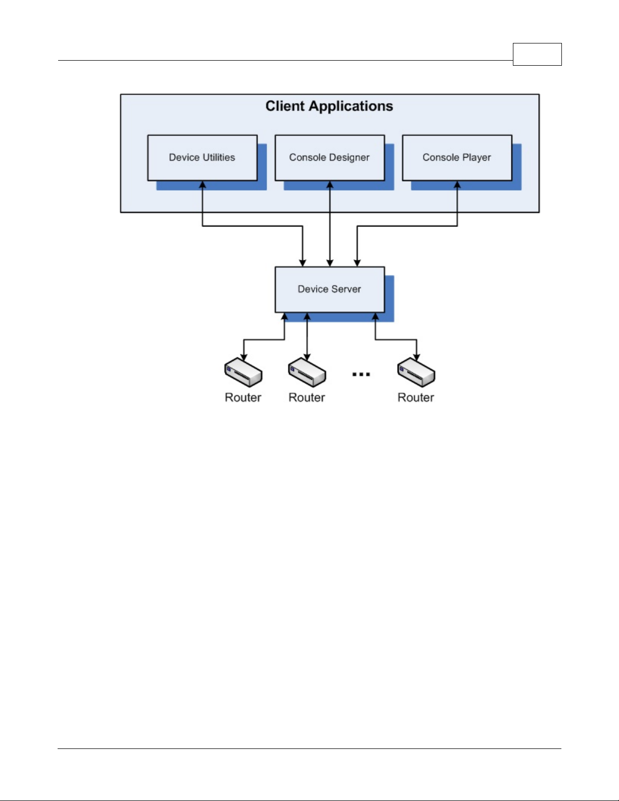
Each of the three types of users interact with a system using three different client applications. Access
to each of the client applications is controlled through a user login. Users configured in a given system
are identified as either Administrator, Designer, or Operator. Administrators have authority to access
all three client components but are primarily concerned with Device Utilities; Designers may access
Console Designer and Console Player; and Operators may only access Console Player and only
those consoles assigned to them by the Designer.
This section provides an overview of each of the Client Components that comprise TyLinx Pro
defines how each of these components serve to fulfill the needs of the Administrator, Designer and
Operator.
1.1.1 Device Server
Device Server
The Device Server is a Windows Service that starts when the computer upon which it is installed
starts. It sits in an idle state until called upon by one of the client applications. When called upon, the
Device Server expects that all physical channels (serial, TCP/IP, and UDP/IP) to which routers are
connected are immediately available for its use. However, when not active and when all client
applications have been closed, the Device Server will free all physical channels.
To perform any device control functions, one or more devices must be configured into the TyLinxPro
database. The Device Server then accesses device configuration to gain control over attached
TyLinx ProTM Architecture
TM
and
© 2012 Sierra Video Systems
Page 12

TyLinx Pro Help12
devices.
1.1.2 Device Utilities
Device Utilities is a client application that is used by Administrators to add devices, test their
connections, and perform various configuration level activities with respect to such devices.
1.1.3 Console Designer
The Console Designer is a client application used by Designers to create Operator control consoles.
An Operator control console contains the controls needed to perform switching of audio/video routing
switchers as well as control content sources and destinations.
1.1.4 Console Player
The Console Player is a client application used by Operators to control audio/video equipment. When
a user logs in, Player loads only those console to which the user has been assigned access. Thus
access to system resources is primarily controlled by the consoles which a particular user may
access.
© 2012 Sierra Video Systems
Page 13

Installation
Part
Page 14

TyLinx Pro Help14
2 Installation
Installation
Requirements for TyLinx Pro:
1. PC Compatible running Windows XP SP2 or Vista
2. 512MB of memory, 1GB or more recommended for routers larger than 32x32
3. 1GHz or faster processor
4. 1024x768 or higher resolution
5. Microsoft SQL Express 2005 (installs during TyLinx Pro installation)
6. .NET Framework 3.5 (install during TyLinx Pro installation)
To install TyLinx Pro, place the CD into the drive. If autorun is enabled the setup will start
automatically. If autorun is not enabled, choose the CD drive from Windows Explorer and double click
setup.exe. The setup wizard will ask you several question including agreeing to the end user's
licensing agreement (EULA). Once agreed to click the Next button until the installation begins. You
will be given the opportunity to set the installation folder for the application. It is recommended that
you leave this at its default setting but not required.
After the installation process is complete you will have 3 new icons on your desktop called TyLinx Pro
Device Utilities, TyLinx Pro Console Designer and TyLinx Pro Console Player. Please refer to the
appropriate help sections for those applications.
© 2012 Sierra Video Systems
Page 15

Quick Start
Part
Page 16
TyLinx Pro Help16
3 Quick Start
Quick Start
The following section contains procedures to do a "simple and quick" setup of your router. For more
advanced setup and configurations see details in the "Admin Utilities", "Console Designer", and
"Console Player" sections of this manual.
Install TyLinx Pro from the CD included with your order. TyLinx Pro can also be downloaded from the
Sierra Video Website http://sierravideo.com/en_software.html
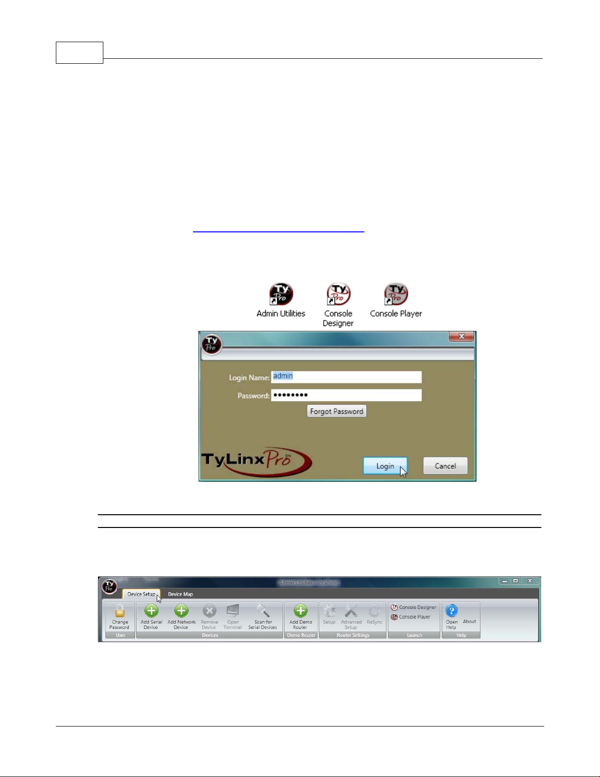
Three icons are placed on your PC desktop.
Open “Admin Utilities”.
Enter the login name and password. Click on “Login”.
Note:
The factory default login name is “admin”; the Password is “password” (case sensitive).
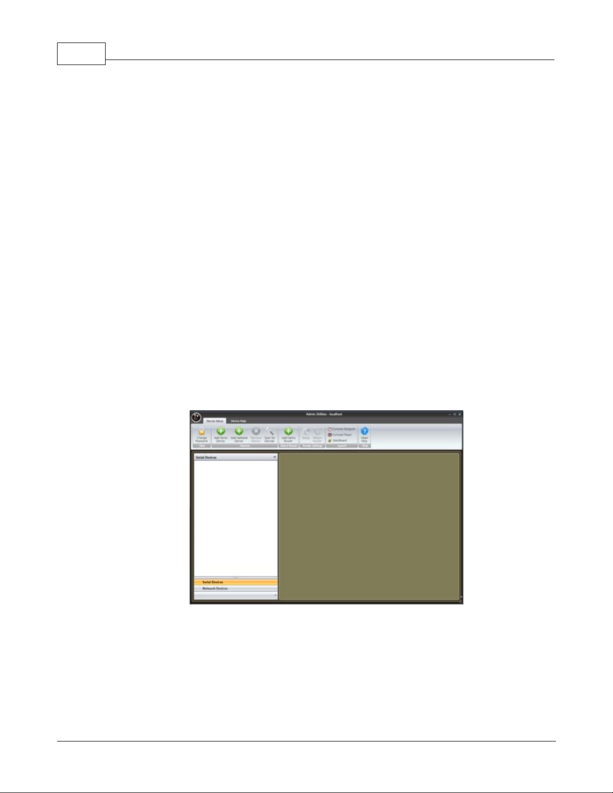
From the Admin Utilities screen, select “Device Setup” tab.
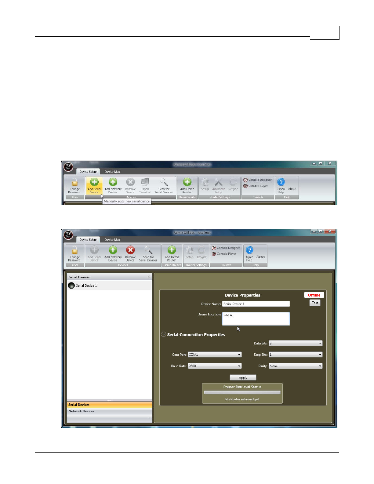
To add a serial device;
Select "Add Serial Device"
© 2012 Sierra Video Systems
Page 17
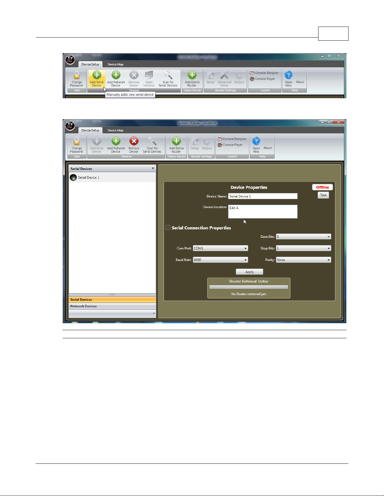
Enter the connection information for the device and select “Apply”.
Quick Start 17
Note:
The connection can be tested by pressing "Test" before proceeding.
© 2012 Sierra Video Systems
Page 18
TyLinx Pro Help18
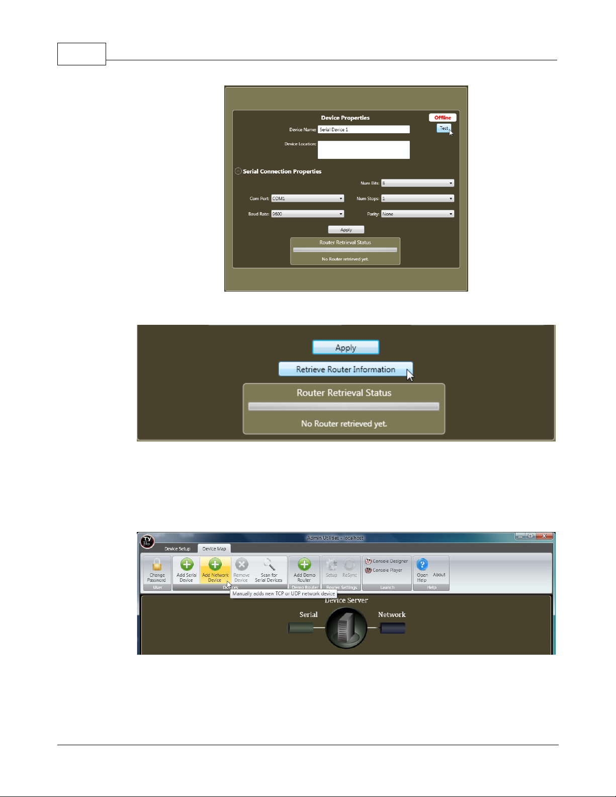
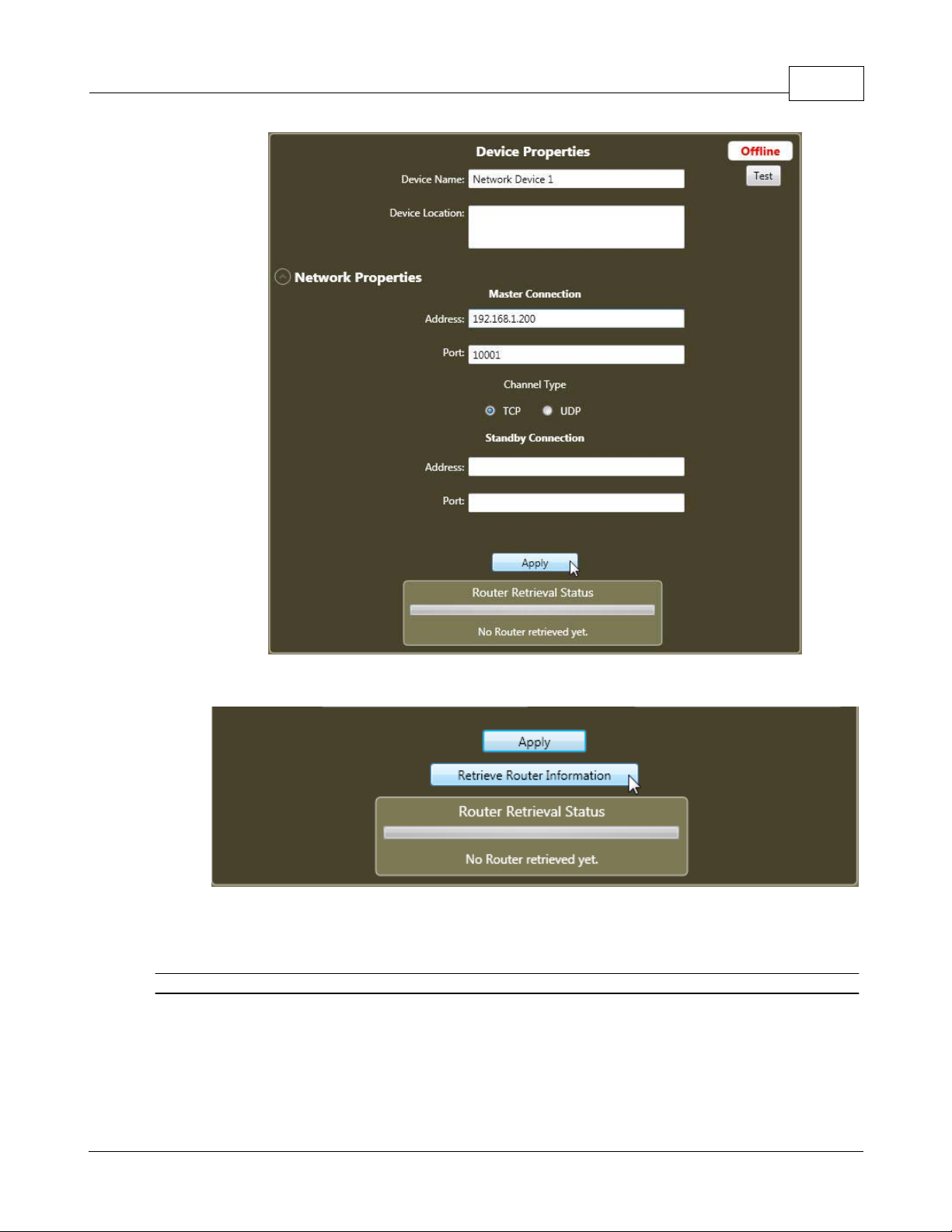
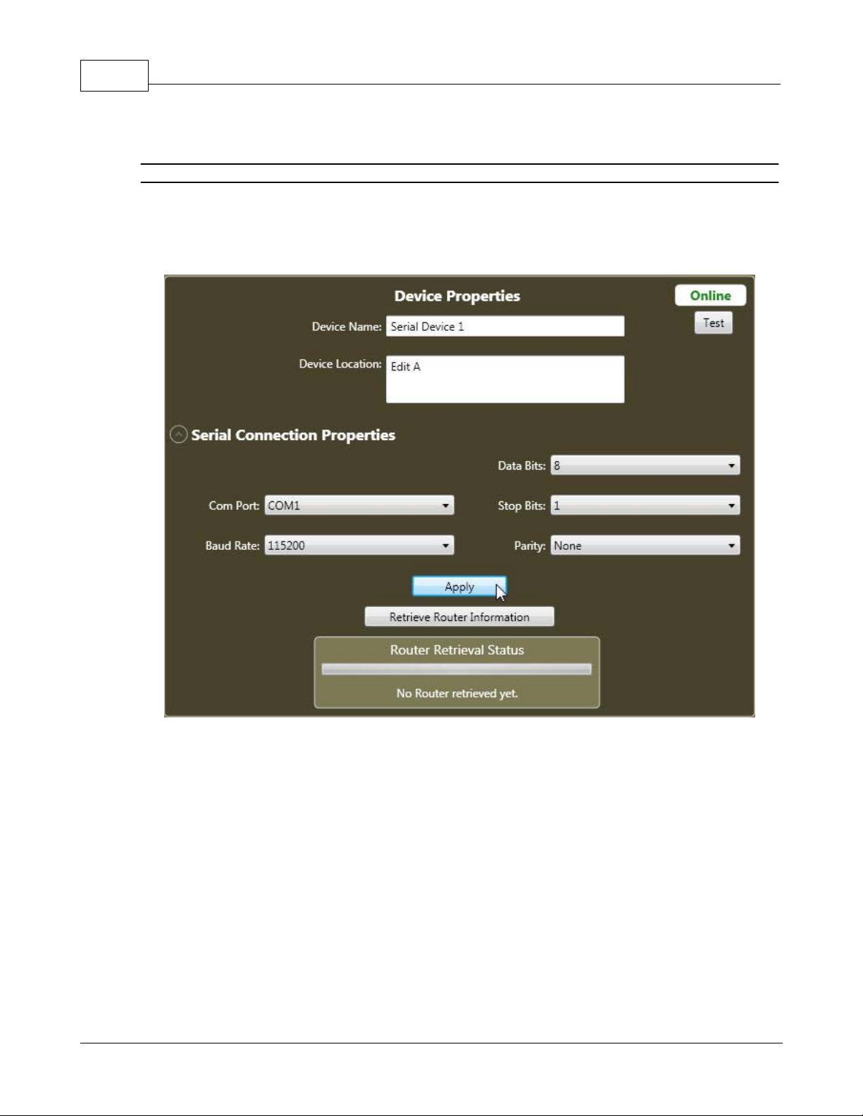
After selecting "Apply", select "Retrieve Router Information" to read the router's current configuration.
To add a Network device;
Select "Add Network Device"
Enter the connection information for the device and select “Apply”.
© 2012 Sierra Video Systems
Page 19
Quick Start 19
After selecting "Apply", select "Retrieve Router Information" to read the router's current configuration.
** A demo router can be added by clicking on "Add Demo Router". This will enable you to "simulate" a
router without an actual router attached.
When a demo router is selected, proceed to "Player" or "Console Designer".
Note:
Connection settings must match the settings in the device. See specific device users guide for factory
defaults or changing communication settings.
If a “Connection is Invalid” is displayed, check cabling and internal device settings.
© 2012 Sierra Video Systems
Page 20
TyLinx Pro Help20
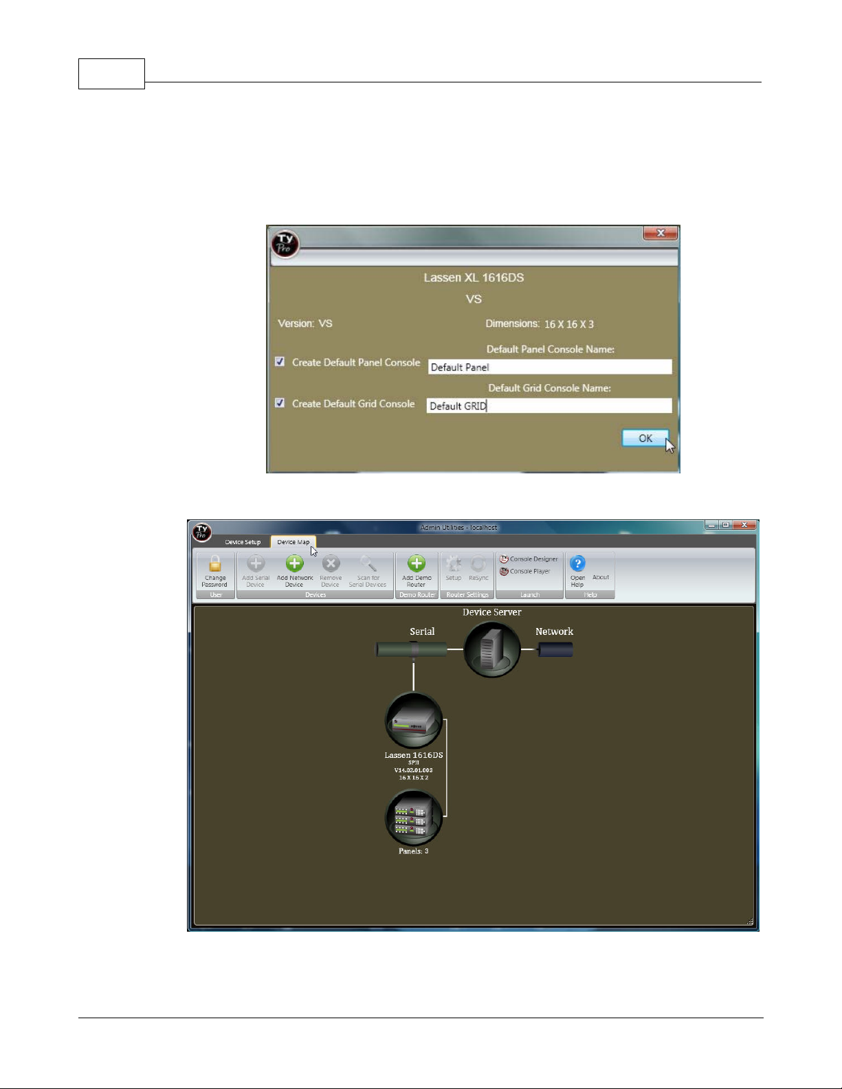
A screen will display indicating the router’s name, size, and version.
This screen allows you to configure the “Player” (router control) screen with basic default switching
screens.
Place a check in the box and enter a name for the panel if you want to configure a "default" panel
and/or grid screen.
Click OK when done. In this example the names "Default Panel" and "Default GRID" are used.
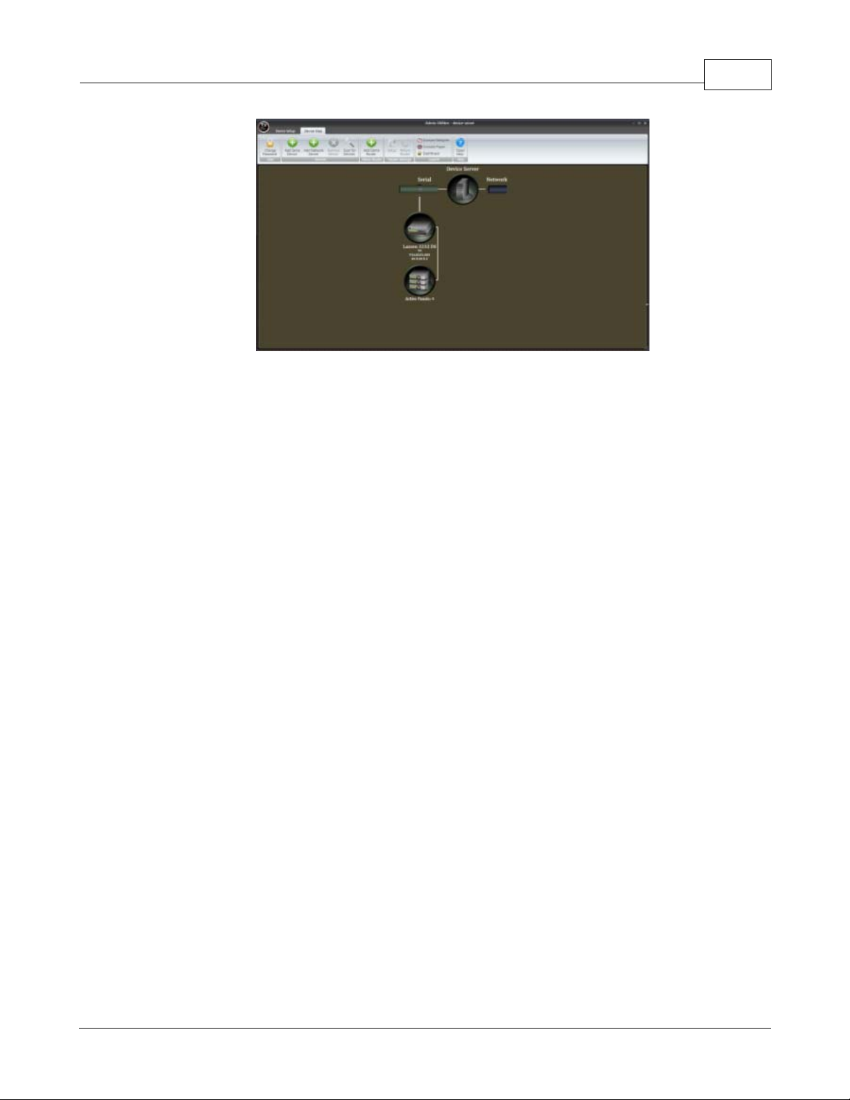
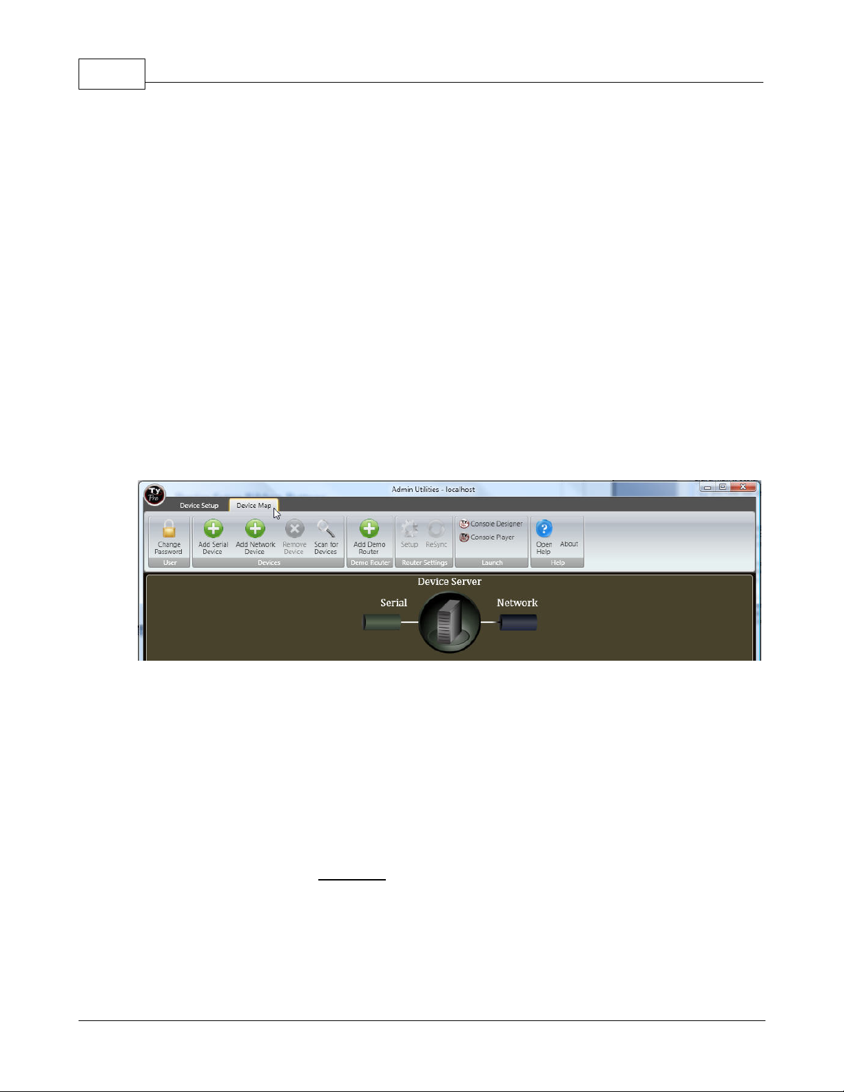
Select the "Device Map" tab.
The Device Map screen will show the "Device Server" (your PC), router, and any connected control
panels.
© 2012 Sierra Video Systems
Page 21
Quick Start 21
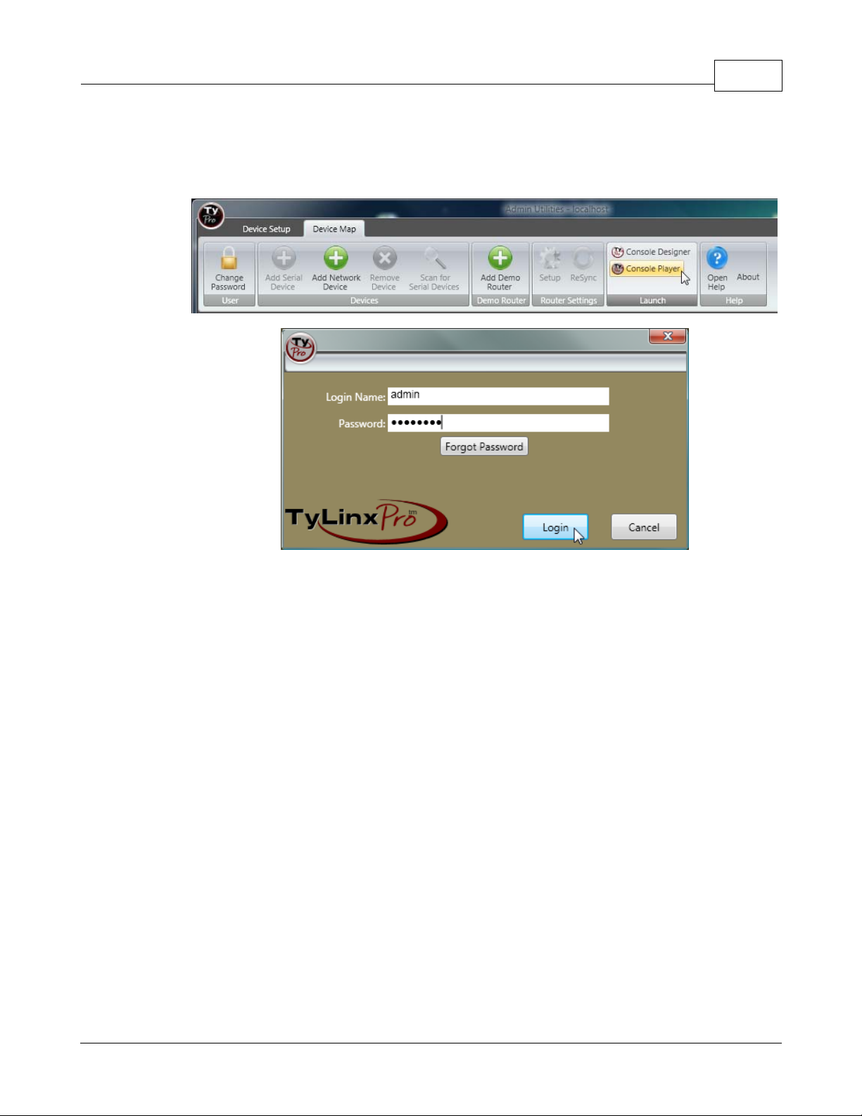
From the Admin Utilities screen (or desktop Icon) select “Launch/ Console Player”.
Enter a login name and password (The factory default login name is “admin”; the Password is
“password”, case sensitive).
© 2012 Sierra Video Systems
Page 22
TyLinx Pro Help22
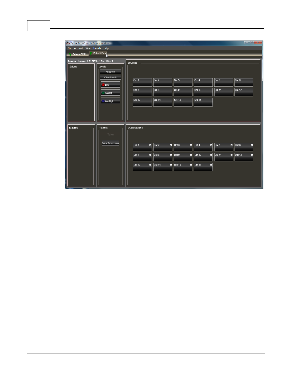
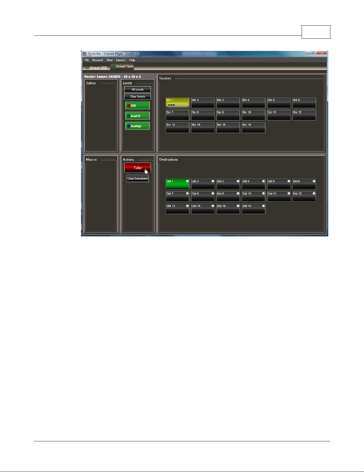
The Player screen will have the default consoles made in the previous instructions.
Click on the Default Panel tab.
To switch the router, click on a Destination.
Select a Source and the level buttons will illuminate, indicating "preset to switch" (enabled).
Clicking on a level button will "deselect" the level to be switched.
The take button will illuminate (preset).
Click on the Take button to initiate the switch.
© 2012 Sierra Video Systems
Page 23
Quick Start 23
Status can be read by hovering over a destination button, with the mouse pointer. The Source
currently connected to that Destination will illuminate yellow.
You can also hover over a Source button and the Destination(s) that the Source is connected to will
illuminate.
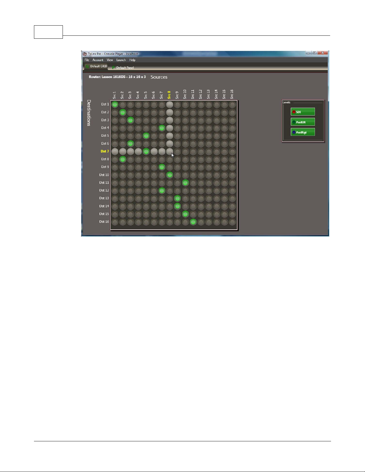
Click on the Default GRID tab.
To perform an all-levels take on the grid console, first select all levels (green indicates enabled) then
click the node symbol that intersects the input and output. The illustration below demonstrates how to
connect Dst 7 to Src 8:
© 2012 Sierra Video Systems
Page 24
TyLinx Pro Help24
© 2012 Sierra Video Systems
Page 25

Admin Utilities
Part
Page 26
TyLinx Pro Help26
4 Admin Utilities
Admin Utilities
This section provides a detailed explanation of the Admin Utilities client and how the Administrator
uses this tool to register devices into the system and configure them.
4.1 Overview
Overview
TyLinx Pro Admin Utilities version 2.0 introduces full featured configuration to the TyLinx Pro line-up.
With this new release the software can do things such as: adjust gains, toggle equalizers, toggle slew
rates, setup control panels, and many other options that were not available in the previous release.
Admin Utilities is part of a three program suite that allows for the creation of a network of routers for
configuration and control. It plays a vital role in this suite by allowing the addition and deletion of
devices and the screens to configure the properties in them. This is a brief outline of those screens
and what they will enable the user to setup and configure in Sierra Video routers.
Quick summary of Setup Screens
General Screens
Device Setup – provides a typical view of the devices connected to TyLinx Pro. The devices
are all listed on the outlook bar, which is the box to the far left of the screen that contains the
serial and network category groups and devices within those categories. A device is any
peripheral that is connected to TyLinx Pro; in the case of 2.0 these devices will only represent
Sierra Video routers. With the Device Setup screen all the connection settings can be
changed for devices added to TyLinx Pro.
© 2012 Sierra Video Systems
Page 27
Admin Utilities 27
Device Map – provides a visual representation of the system topology. You cannot change
connections settings on this screen; however, you can perform all the setup actions available
on the Device Setup View. This view also tells you at a glance which of the routers has panels
connected and there quantity. Once a device is loaded into TyLinx Pro this screen will show
up on startup.
Setup Screens
Router Communications – the first screen that appears when opening the router setup
window. This screen is used to configure the network and serial port settings in the router.
Names –changes the Destination, Source, and Level names in the router.
Salvos – add, delete, and setup salvos in the router.
Audio Gains – adjusts both the input and output gains in the router, if the levels support the
feature.
Output Slew – set the slew of an output to either SD or HD on supported levels.
Input Equalizers –toggles input equalizers on or off for supported levels.
Room Grouping – configures the room groups in supported routers.
Alarm Setup Screen – setup the alarms in supported routers.
Reclockers – adjust reclockers in supported routers.
Advanced Setup
Dimensions – changes the virtual source, destination, and level size of the router.
Mapping – virtually maps the router and import/export from Excel.
Layers – configures the hardware layers in the router and maps them to virtual levels.
© 2012 Sierra Video Systems
Page 28
TyLinx Pro Help28
Microprocessors – upgrades the microprocessor software in the router’s boards.
*TyLinx Pro currently supports Sierra Video Systems routers only.
4.2 Add a Device
Add a Device
Open Admin Utilities;
Select the "Device Map" tab.
The Device Map screen provides a visual representation of the system topology. You cannot change
connections settings on this screen; however, you can perform all the setup actions available on the
Device Setup View (see "Device Setup"). This view also tells you at a glance which of the routers has
panels connected and there quantity. Once a device is loaded into TyLinx Pro this screen will show
up on startup.
Device Setup Ribbon Buttons
Change Password – opens a screen where you the user’s password can be changed.
Add Serial Device – adds a serial device to the server.
Add Network Device – adds a network device to the server.
Remove Device –removes a device from the server. The user is prompted with a confirmation dialog
to ensure devices are not deleted accidentally.
Scan for Devices –scans all serial ports
router is discovered it will automatically be uploaded to TyLinx Pro.
Add Demo Router –adds a demo router to TyLinx Pro for demonstration purposes.
Setup –opens the general router setup screen.
available to the server and looks for Sierra Video routers, if a
© 2012 Sierra Video Systems
Page 29
Admin Utilities 29
ReSync – resynchronize TyLinx Pro with the router. Any changes that have been made to the router
from an outside source will reflect in TyLinx Pro after the resynchronization is complete.
Launch Menu – The Launch menu provides a means to start other applications associated with
TyLinx Pro operations. You can launch the other programs simply by clicking on their icon.
Add a Serial Device;
This section is if communication to the router is via a serial connection. For IP communication, skip to
the section below "Add a Network Device".
Select Add Serial Device;
A dialog will now appear that looks like the following:
© 2012 Sierra Video Systems
Page 30
TyLinx Pro Help30
Enter the serial connections that apply to your router.
Note:
Connection settings must match the settings in the device. See specific device users guide for factory
defaults or changing communication settings.
Select Apply;
When communication with the router is successful, the display in the upper right will indicate "Online".
After selecting "Apply", select "Retrieve Router Information" to read the router's current configuration.
© 2012 Sierra Video Systems
Page 31

Admin Utilities 31
A screen will display indicating the router’s name, size, and version.
This screen allows you to configure the “Player” (router control) screen with basic default switching
screens.
If you want to create a default control panel and/or Grid, place a check in the box and enter a name
for the panel if you want to configure a "default" panel and/or grid screen.
Click OK when done. In this example the names "Default Panel" and "Default GRID" are used.
© 2012 Sierra Video Systems
Page 32

TyLinx Pro Help32
Add a Network Device;
Setting up a network device is very similar to setting up a serial device in Admin Utilities. The first step
is to press the “Add Network Device” button located to the right of the “Add Serial Device” button. This
will add a new network device into TyLinx Pro and select it.
Select Add Network Device;
A dialog will now appear that looks like the following:
© 2012 Sierra Video Systems
Page 33

Admin Utilities 33
The window has everything to configure the network device. It also has a second address field for
redundant processors. The Standby Connection properties are required when the router has
redundant processors with IP. Once the correct settings are entered press the apply button and if the
router is online it will bring up the “Retrieve Router Information” button, press that and the rest of the
steps are the same as adding a serial device.
Enter the Network connection information that applies to your router.
Once the correct settings are entered press the apply button and if the router is online it will bring up
the “Retrieve Router Information” button, press that and the rest of the steps are the same as adding
a serial device.
Note:
Connection settings must match the settings in the device. See specific device users guide for factory
defaults or changing communication settings.
© 2012 Sierra Video Systems
Page 34

TyLinx Pro Help34
4.3 Testing a Connection
Testing a Connection
Click the Test Connection button on the Device Settings dialog to test the interface to a device. A test
pass/fail indication will be presented following test. If the connection is valid, it means that TyLinx Pro
has what it needs to communicate with the device.
If invalid, then some trouble shooting may be required. Some questions to ask that may lead to the
problem are:
is the device powered?
is the communications cable connected?
is the Connection Type set properly?
for serial connections; are properties like baud rate, number of bits, handshaking, etc. set to
router's configuration?
for network connections; are the IP address and/or port number set correctly for TCP or UDP
connection?
4.4 Retrieve Device Information
Retrieve Device Information
Once device communications configuration has been defined and tested, the Administrator should
click the 'Retrieve Device Information' button. This will direct Device Utilities to interrogate the device
for the initial device configuration for the database.
© 2012 Sierra Video Systems
Page 35

Admin Utilities 35
Once the information has been retrieved, the Administrator will be presented with a dialog that will
permit them to create 2 default control consoles. The image below shows the Router Configuration
dialog:
Notice on the dialog shown above, that 2 default control consoles may be created and named. Enter a
meaningful name for both control consoles as they will be used later to identify consoles during
operations. When complete, click the OK button and Device Utilities will create the default control
consoles. Uncheck either Create Default Panel Console and/or Create Default Gird Console if one or
more default console are not to be created.
4.5 Router Setup
Router Setup
The following sections apply to setting up the router's names and operational options.
Access to these features are available by selecting "Setup" from the menu bar on the Device Setup
tab or double clicking on the router icon in the Device Map tab.
© 2012 Sierra Video Systems
Page 36

TyLinx Pro Help36
Not all setup options are available on all models. See the router's Users Manuals for information on
options available.
4.5.1 Router Names
Router Names
The router comes with default names “Src” and “Dst”.
If the router inputs, outputs, and levels have been previously named, TyLinx Pro will display the
names currently programmed in the router. You may want to change these names to meet your
needs.
Names consist of a category and index, such as VTR 1. VTR (short for video tape recorder) as the
category with the number 1 as the index. All VTRs would have the same category (VTR) with a
different index for each video tape recorder.
This method allows you to categorize common inputs or outputs, making naming and switching of
inputs and outputs simpler with the programmable SCP series of remote control panels.
Note:
Names can also be typed in (not to exceed 8 characters).
To edit source, destination, and level names, select Setup from the menu.
© 2012 Sierra Video Systems
Page 37

Then select the "Names" tab.
The edit names dialog appears as shown below:
Admin Utilities 37
Router Name Edit Dialog
© 2012 Sierra Video Systems
Page 38

TyLinx Pro Help38
To change the names highlight the name to change by clicking on it and then enter a new name.
Select a category from the category list on the right. (To enter a new category see "Categories"
below.)
The selected category will be entered and the window will switch to "Indices".
Then select an Index reference.(To enter a new index reference see "Indices" below.)
© 2012 Sierra Video Systems
Page 39

Admin Utilities 39
Categories
To add a new category, select "New Category".
© 2012 Sierra Video Systems
Page 40

TyLinx Pro Help40
Enter a new category name, press enter.
The new category will appear on the category window.
© 2012 Sierra Video Systems
Page 41

Admin Utilities 41
Note:
Category names may not exceed 5 characters.
A category may be renamed or deleted by right clicking on the category button and selecting the
function.
Indices
To add a new index, select "New Index" from the Indices window.
© 2012 Sierra Video Systems
Page 42

TyLinx Pro Help42
Enter a new index reference, press enter.
The new category will appear on the category window.
© 2012 Sierra Video Systems
Page 43

Admin Utilities 43
Note:
Index names may not exceed 5 characters.
An index may be renamed or deleted by right clicking on the category button and selecting the
function.
Changes will be saved in the database and sent to the router as you change focus to other name
fields or click close, thus there is no need for an explicit 'Save' action.
When names are changed in this screen the names are sent to the router and will be reflected on the
front control panel and remote panels with displays.
Names are limited to 8 characters including spaces.
DO NOT repeat names in either the Source or Destination column. Source names can be repeated in
the Destination column and vice-versa.
4.5.2 Salvos
Salvos
A Salvo is a list of crosspoint switches that are downloaded to the routing switcher and switched by a
single “Salvo Take” command.
© 2012 Sierra Video Systems
Page 44

TyLinx Pro Help44
Salvos are stored in the router's CPU and may be accessed by any or all users.
© 2012 Sierra Video Systems
Page 45

Salvo Setup
From the "Setup" window, select the Salvo tab and "Add"
Admin Utilities 45
Enter a salvo name in the dialog box and click "OK".
© 2012 Sierra Video Systems
Page 46

TyLinx Pro Help46
Click on "Add" takes.
Configure the Salvo by selecting the destination(s), sources, and levels from the list below.
More than 1 destination may be selected by holding the "Shift" or "Ctrl" button on the keyboard and
selecting multiple destinations.
When more than 1 destination is selected, the "Add Multiple Takes" must be selected to include all
switches.
All Salvos are sent to the router's CPU when the Salvo window is closed.
© 2012 Sierra Video Systems
Page 47

4.5.3 Audio Gain
Audio Gain
For units with an adjustable audio gain option, select the "Audio Gains" tab from the Setup window.
The current gain settings are read from the router when the "Audio Gains" window is opened.
Admin Utilities 47
Input Gain Adjust
Select inputs.
Gain is adjusted by hovering over the fader, holding down the left mouse button, and moving the fader
up or down.
© 2012 Sierra Video Systems
Page 48

TyLinx Pro Help48
The amount of gain or attenuation is indicated to the left of the fader.
To set gain to unity, click on "Set to Unity" or to set all gains to unity select "Set to All".
Output Gain Adjust
Select outputs.
Repeat process as described above for input gains.
Outputs can be set to "Mute" by placing a check in the appropriate box.
© 2012 Sierra Video Systems
Page 49

4.5.4 AV Muting
A/V Muting
Admin Utilities 49
Overview
Some models of Sierra Video routers have the ability to adjust A/V Muting. If your router has this
option, the following section describes the steps necessary to adjust A/V delay.
A/V muting (delay) is a function that “delays” the video and audio signal of an output for a “user
adjustable” amount of time after a “take” command is sent to the processor. The sync signals will be
immediately upon the “take” command; only the video and audio will be delayed.
This enables the projector (or monitor) time, if input sync rates vary, to adjust to differing sync rates.
The video will display black for a user set duration while the sync only is sent to the output device.
Setting Mute Delay
For Sierra Pro units with an "A/V Muting" option, select the "AV Muting" tab from the Setup window.
© 2012 Sierra Video Systems
Page 50

TyLinx Pro Help50
Mute Delay, in seconds, is adjusted by hovering over the fader, holding down the left mouse button,
and moving the fader up or down.
Changes are immediately sent to the router.
4.5.5 Room Grouping
Room Grouping
Overview
Room Groupings are groups of user defined inputs and outputs. If your router is being switched from
© 2012 Sierra Video Systems
Page 51

Admin Utilities 51
several locations (rooms), you may want to restrict the inputs and/or outputs controlled by each
location.
As an example, your router is being switched from two locations, a boardroom and a conference room
and the boardroom uses different outputs and inputs than the conference room. To prevent accidental
switching of the boardroom outputs or inputs from the conference room or vice versa, you can restrict
the ability of input and output control of each location by setting up “rooms”.
You can also restrict the “level” the room can switch. If you have a video (level 1) and a audio level
(level 2) for a given input, but only the boardroom to switch the audio (level 2), you can restrict the
ability of the boardroom so that only the audio of that input is switched from that room group.
Sierra Video routers hold up to 4 room groups.
Group Setup
For Sierra Pro units with an "Room Grouping" option, select the "Room Grouping" tab from the Setup
window.
Select "Add" Groups.
© 2012 Sierra Video Systems
Page 52

TyLinx Pro Help52
Enter a Room Name.
Inputs, outputs, and levels allowed in the room group are selected by clicking on the appropriate
areas.
© 2012 Sierra Video Systems
Page 53

Admin Utilities 53
All Room Groups are sent to the router's CPU when the Room Grouping window is closed.
4.5.6 Sync Rate Reporting
Sync Rate Reporting
Overview
Some models of Sierra Video routers have the ability to report sync rate using TyLinx Pro. If your
router has this option, the following section describes the steps necessary to report sync rate.
Reporting of the Sync Rate on an input can help troubleshoot installation wiring and determine if a
scaler is required.
Reporting Sync Rates
For Sierra Pro units with an "Sync Rate Reporting" option, select the "Sync Rates" tab from the Setup
window.
© 2012 Sierra Video Systems
Page 54

TyLinx Pro Help54
Sync rates are displayed in the individual source box(s).
4.5.7 Input Equalizers
Input Equalizers
Overview
Some models of Sierra Video Digital routers offer adjustable input equalizers. This
function allows users to bypass any input's auto ranging equalizer.
In the 'ON' mode: The input equalizer is enabled and the routing switcher will
automatically adjust to the cable length connected to the input.
In the 'OFF' mode: The input equalizer is bypassed, and the routing switcher will not
do any cable equalization.
© 2012 Sierra Video Systems
Page 55

Admin Utilities 55
'ON' is the recommended and is the factory default setting.
Input Equalizer Setup
For units with an "Input Equalizer" option, select the "Input Equalizers" tab from the Setup window.
Equalizers are turned on and off by clicking on the On/Off button in the source box.
Multiple sources can be changed by placing a check in the source's box and selecting "Turn Selected
On" or "Turn Selected Off" at the top of the window.
© 2012 Sierra Video Systems
Page 56

TyLinx Pro Help56
Changes are sent to the router upon selection.
4.5.8 Output Slew
Output Slew
Overview
Some models of Sierra Video Digital routers offer adjustable output slew rate. This
function allows users to adjust the slew rate of each output to cope with the varying
formats that the router accepts.
In the 'HD' mode: The router complies with the <= 270psec rise and fall time
spec defined in the SMPTE 292M standard
In the 'SD' mode: The router complies with the >= 400psec and <=1500psec rise and
fall time spec defined in the SMPTE 259M standard.
'HD' is the factory default setting.
Note that if the Slew Rate is set to HD, the routing switcher will pass HD and SD
signals correctly. However a HD signal will not be passed through the routing
switcher if the Slew Rate is set to “SD”.
Output Slew Rate Setup
For units with an "Output Slew Rate" option, select the "Output Slew" tab from the Setup window.
© 2012 Sierra Video Systems
Page 57

Admin Utilities 57
Output Slew is changed by placing a check in the SD or HD box for the appropriate output.
Multiple outputs can be changed by placing a check in the output's box and selecting "Set Selected
To HD" or "Set Selected To SD" at the top of the window.
© 2012 Sierra Video Systems
Page 58

TyLinx Pro Help58
Changes are sent to the router upon selection.
4.5.9 Advanced Setup
Advanced Setup
The Advanced Setup window contains functions that can cause the router to operate
incorrectly or to not operate at all.
Any changes made to this window should be made with the assistance of a Sierra
Video technician.
The following sections apply to setting up the router's Mapping.
Access to these features are available by selecting the router icon in the Device Map tab and pressing
"Ctrl/W" on the keyboard.
© 2012 Sierra Video Systems
Page 59

Admin Utilities 59
Select "Advanced Setup" from the menu bar to access the Advanced Setup window.
The "Dimensions" tab displays the current router size allowing entry of new dimensions (see following
sections).
© 2012 Sierra Video Systems
Page 60

TyLinx Pro Help60
The "Mapping" tab displays the current "virtual" I/O verses the connector number related to the virtual
I/O.
This screen allows changes to the router's mapping tables
© 2012 Sierra Video Systems
Page 61

Admin Utilities 61
4.5.9.1
The "Layers" tab displays the layer/level configuration of the router. This is a "read-only" screen and
does not allow changes to the router.
Mapping
Mapping
Overview
Sierra Video routers are shipped configured as “linear mapped”. That is, all levels switch at the same
time when an I/O is selected.
The term one-to-one mapping, or linear mapping, means that source 1 is assigned to physical input
connector 1, source 2 to connector 2, etc. This is the default mapping that is shipped with each Sierra
router. If one-to-one mapping is adequate, you do not need to follow the instructions in this section for
setting the mapping tables.
In non-mapped (linear mapped) Sierra routers, when a control panel or control program calls for a
connection, or “take”, from source 3 to destination 18, this means that the signal going to the physical
input connector labeled “3” is to be connected to the physical output connector labeled “18”.
Sierra Video routers offer the option of “Virtual Mapping”. In virtual-mapped Sierra routers, a mapping
table stands between the control panel “take” request, and the physical connectors that are switched.
Its purpose is to give the user more flexibility in the way signals are connected to the router, and the
way numbers are assigned to the signals by the router.
© 2012 Sierra Video Systems
Page 62

TyLinx Pro Help62
Source and destination names (virtual names) apply to all levels. That is, you cannot give different
names to a given source on each level. You can only give it a single name that must apply to all
levels. Think of (virtual) source names as names given to source numbers, and think of (virtual)
destination names as names given to destination numbers. Input and output names may be different
on each level. That is, an input may be given one name on level 1, and an entirely different name on
level 2. Think of input names as names given to input connectors, and output names as names given
to output connectors.
Often, an input’s name will be the same on all levels, and likewise for an output’s name. Furthermore,
it will often be the case that a source’s name will be the same as the name of the input it is mapped to,
and likewise for destination names. However, it’s your choice.
A user typically controls a routing switcher by using a control panel to enter and view destination,
source, input and output names and numbers. Below is a summery of the typical process a user
would go through to examine and take a destination using a control panel:
1. Destinations are shown and selected by the user using the destination name and/or the destination
number. The physical output number that the destination maps to, or its name, is not shown on the
control panel.
2. The crosspoint status of a destination is usually shown using the physical input names and/or
numbers on each level. There are two reasons why the virtual source names/numbers are not used:
(a) source names apply to all levels, while input names can be different on each level, and it is often
important when displaying status to be able to see different names on each level; (b) if multiple
mapping is used, displaying the input name rather than the source name reduces confusion by
showing the actual physical signal name, which will be the same for two different source names
with multiple mapping. Because names are often the same on all levels, and the same for a source
and its mapped input, it will often be the case that if source names had been displayed instead, they
would be the same.
3. Some control panels allow the crosspoint status of a destination to be viewed using source names
and/or numbers rather than input names/numbers. The SCP series of control panels can be set to
show status in either form (source names or input names). It is user selectable when programming
the control panel using the SVS GRIP router control software.
4. Takes are composed by the user using either source or input names, or source numbers. A user may
enter either a source name or an input name or a source number for each level of the take he is
composing. An entered name is looked up in both the source and input name tables, to locate the
source number to use for the take. If the name is found in the input name table, the first source that
is mapped to that input is used. The behavior is slightly different depending on whether he is
composing an all-levels (AFV) take, or a breakaway take. If an all-levels take is being composed,
the name is first looked up in the source name table, and if not found, the input name table is
searched for the name. If a breakaway take is being composed, the search order is just the opposite,
with the input name table searched first, and then the source name table. In many cases the search
order would make no difference, because the same names are used for source and its mapped input.
The number of sources and destinations in a Sierra virtual-mapped router can be configured by
the user. It can be many more than the physical size of the router, which can be useful in different
ways.
There are many uses for virtual mapping, such as:
rtual sources can be mapped in such a way as to permit an all-levels take of that source to
1. Vi
accomp
lish what would previously have to have been done with a breakaway take. You could map
some virtual sources on all levels, while mapping others on only a few levels, and leaving other
levels unmapped. This permits doing all-level takes that affect only some levels.
2. You may wish to keep all the signals from one type of machine grouped together in the same group
of source or destination numbers, and yet you may want to hav e the flexibility to add more of these
signals at a later time without having to move a lot of signals from one connector to another.
Suppose that VTR1-VTR8 are assigned to input connectors 1-8, and CAM1-CAM12 are assigned
to input connectors 9-20. The mapping table is set up so that sources 1-8 are VTR1-VTR8, and
sources 9-20 are CAM1-CAM12. Later on, you add VTR9, and you want to make it be source 9,
and make CAM1-CAM12 be sources 10-21. But at the same time you do not want to have to move
© 2012 Sierra Video Systems
Page 63

Admin Utilities 63
all the connectors CAM1-CAM12 down one. You could put VTR9 on input connector 21, and map
source 9 to input 21. You would have to change the mapping of sources 10-21 so that they mapped
to inputs 9-20.
3. In partially-stuffed routers with holes, mapping allows the holes to be “mapped away”, so that
control panels see one continuous set of sources or destinations.
4. Two separate levels can be “joined together” into one level, by mapping first one level, then the
other, to successive sources or destinations. For example, suppose you have two levels, each 16x16.
Sources 1-16 could be mapped to level 1 inputs 1-16 with level 2 unmapped. Sources 17-32 could
be mapped to level 2 inputs 1-16 with level 1 unmapped. Likewise for destinations. You would not
be able to connect source 1 to destination 17, for example, but you could connect any source 1-16
to any destination 1-16, or any source 17-32 to any destination 17-32. You would not have to
concern yourself with levels.
5. A more complete join of two levels could be done by cabling inputs of the two levels together. For
example, if you had a router with two 64x64 analog video levels, you could connect 64 inputs to
the first level and then cable them in parallel to the second level also, so that both levels received
the same 64 inputs. Then, you could map destinations 1-64 to level 1 outputs 1-64, and destinations
65-128 to level 2 outputs 1-64. You would end up with a 64x128 single-level router.
6. One source could be mapped on all levels, while another one might be mapped only on audio
levels. The first would be used to set up all levels of a destination, while the second would be used
to change the audio while leaving the video unchanged. An all-levels take could be done with the
second source, yet only the audio levels would change. Note that this is a use of multiple mapping.
7. If one level is a machine control level, you can selectively map that level only for those sources or
destinations where you want machine control routing to take place.
8. Some signals may include video but not audio, or vice-versa. For these signals, mapping table
entries can be unmapped on those levels where there is no signal. Router inputs and outputs need
not be wasted. For example, if output 17 is used for a monitor’s video signal on level 1 and for a
totally unrelated audio signal on level 2, separate destinations can be mapped to each level,
permitting all-level takes of the MON that don’t affect the audio level, and vice-versa.
Offset Mapping
The most simple and common form of virtual mapping is to separate signal types. This is referred to
as "offset" mapping. An example of this would be a 16x16 two level router. Level 1 being digital video
and level 2 as analog video. Since selecting source 1 to destination 1 will switch both the digital and
analog signals connected to connector 1, a "break-away switch must be made if only the digital video
level is what is desired to switch.
The router can be "mapped" to operate as a 32x32 router with I/O's 1 thru 16 as digital video and I/O's
17 thru 32 as analog video.
TyLinx Pro provides a simple method to accomplish this.
The following examples are for a 16x16 two level router, level 1 being digital video and level 2 as
analog video.
The first step is to expand the router size.
Select the "Dimensions" tab from the menu bar.
© 2012 Sierra Video Systems
Page 64

TyLinx Pro Help64
Enter the Virtual size the router is to be and select "Apply To Router".
Then select the "Mapping" tab from the menu bar.
Select sources to offset.
© 2012 Sierra Video Systems
Page 65

Highlight the sources you want to offset map.
Admin Utilities 65
Select the level(s) to to offset.
Press "Apply Offset Map".
© 2012 Sierra Video Systems
Page 66

TyLinx Pro Help66
After applying offset map you will see the connector numbers change in the mapping table.
Repeat the process for the destinations.
When complete, press "Send Changes to Router".
A countdown window will appear while changes are sent.
When the countdown is complete, press "Reset Router" to store the changes in the router.
© 2012 Sierra Video Systems
Page 67

Admin Utilities 67
The router will reset and mapping will be complete.
The router is now configured to a virtual size of 32x32. The first 16 I/Os are digital video followed by
I/Os 17 through 32 as analog video.
This allows for the operators to separate, by switching, the signal types without doing a “break-away”
switch.
The two signal types will always switch separately.
Complex Router Mapping
When a mapping scheme is required more complex than simple offset mapping. It is possible with
© 2012 Sierra Video Systems
Page 68

TyLinx Pro Help68
TyLinx Pro to generate a excel " Mapping Worksheet" that can be filled out and sent to the router.
From the Mapping tab, select "Generate Mapping Worksheet".
A windows "Save As" dialog box will appear. Enter a name and save.
© 2012 Sierra Video Systems
Page 69

Admin Utilities 69
Open the worksheet and you will see the current mapping and names in your router.
Enter connector numbers and names as desired.
Adding rows will automatically change the virtual size of the router.
When complete, save and close worksheet.
From the Mapping tab, select "Import Mapping Worksheet"
© 2012 Sierra Video Systems
Page 70

TyLinx Pro Help70
A countdown window will appear while changes are sent.
When the countdown is complete, press "Reset Router" to store the changes in the router.
The router will reset and mapping will be complete.
Mapping Examples
In this example the M-100 supports both analog and digital signals therefore both levels are switched
together. VTR-1 is analog only. When VTR-1 is selected only the analog level (level 1) will be
changed.
Overlapping Offset mapped router
Router Sources
Virtual Names Level 1 8x8
Level 2 8x8
I/O Source
Analog
Video
Conn #
Digital
Video
Conn #
© 2012 Sierra Video Systems
Page 71

1 M-100 M-100 1 M-100 1
2VTR 1 VTR 1 2 0
3VTR 2 VTR 2 3 0
4VTR 3 VTR 3 4 0
5VTR 4 VTR 4 5 0
6VTR 5 VTR 5 6 0
7VTR 6 VTR 6 7 0
8VTR 7 VTR 7 8 0
9 DIG 1 0 DIG 1 2
10 DIG 2 0 DIG 2 3
11 DIG 3 0 DIG 3 4
12 DIG 4 0 DIG 4 5
Admin Utilities 71
13 DIG 5 0 DIG 5 6
14 DIG 6 0 DIG 6 7
15 DIG 7 0 DIG 7
8
In this example there are mixed signal formats (audio and video). By mapping this way, when you
select CD 1 only the audio level of the CD is switched. VTR 1 accepts both audio and video, therefore
both levels are switched.
Mixed format mapping
Router Sources
Virtual Names Level 1 8x8
I/O Sources Video Conn # Audio Conn #
1 M-100 M-100 1 M-100 1
2VTR 1VTR 1 2 VTR 1 2
3VTR 2VTR 2 3 VTR 2 3
Level 2 8x8
4VTR 3VTR 3 4 VTR 3 4
5VTR 4VTR 4 5 VTR 4 5
6CG 1 CG 1 6 0
7 CD 1 0 CD 1 6
© 2012 Sierra Video Systems
Page 72

TyLinx Pro Help72
8TBC 1TBC 1 7 0
9DVD 1DVD 1 8 DVD 1 7
10 Audio Rm 0 Audio Rm 8
4.6 Control Panels
Control Panels
Overview
This section applies to all control panels using RS-485 (3 pin mini XLR connector) communication.
Tylinx Pro configures the router for control panels and programs the buttons on the SCP series
programmable control panels.
A Router Is Only As Good As Its Control System...
A good control system is reliable, yet flexible enough to allow the switcher to be controlled in a variety
of ways. It will allow the use of a large number of different control panels. Simple Push Button control
panels to fully programmable panels customized to your individual installation can be configured with
TyLinx Pro.
The physical network structure is RS-485 extended to accommodate a total of up to 64 panels (100
on some models) on a common bus of up to 5,000 feet. The Control System uses a serial protocol
that allows for controlling video and audio levels, AFV, or breakaway. The panel network software is
based on fast polling protocol, the most reliable software method for networking devices on a common
bus. Control panels on the bus can never take over the bus. Instead, the polling master -- which also
is the network interface to the routing switcher -- is always in control.
The Button per Input control panels come in a variety of configurations. These less complex and
easy-to-use panels simply assign a single button to a single input. Single-Bus buttons are assignable
to one output and any combination of levels; the single operation of pressing a switch selects the
desired input. XY Matrix panels have two groups of switches: First press an OUTPUT button to enable
the desired output, then use the row of IN or SOURCE Buttons to initiate the switch.
© 2012 Sierra Video Systems
Page 73

Admin Utilities 73
Configuring Control Panels
After retrieving the router's information a control panel icon will display on the "Device Map" window.
If control panels are added after the router's information is retrieved, select "ReSync" from the menu
bar or right click on the router icon and select "ReSync Router".
© 2012 Sierra Video Systems
Page 74

TyLinx Pro Help74
Double click on the Control Panel icon.
Then select a control panel from the left hand list. Default names for control panels are based on their
specific ID number.
Each control panel must have its own unique ID number (see the specific control panel's manual for
© 2012 Sierra Video Systems
Page 75

details on setting ID numbers).
Admin Utilities 75
This window will indicate the control panel type, panel ID number, and software version.
A control panel name and/or location can be entered (*not required).
© 2012 Sierra Video Systems
Page 76

TyLinx Pro Help76
Destinations and/or Levels can be blocked from control by a panel.
The output(s) the panel can control are selected by "toggling" the destination buttons on or off in the
"Allowed Destinations" window.
Note:
Single bus panels can only control 1 destination.
© 2012 Sierra Video Systems
Page 77

Admin Utilities 77
All, or specific levels, can be controlled by a panel. Select the level(s) to be controlled by the panel by
"toggling" the level buttons on or off in the "Allowed Levels" window.
The “Tally Level” selects which level a Pushbutton panel’s lamps will follow.
Select the Tally Level from the drop down list.
© 2012 Sierra Video Systems
Page 78

TyLinx Pro Help78
If this is a Single Bus control Panel, place a check in the "Single Bus" box.
Configuring Programmable (SCP) Control Panels
The SCP family of panels panels are designed to allow for maximum flexibility in the categorization of
buttons. A button can have multiple functions depending how it is programmed and where the user is
in the sequence of pushes. As an example, the first push on a Button could write “VTR” on the
display. The second push on the same button could add a “1” to “VTR” as a suffix so we would see
“VTR1” on the display. If another number programmed button were pushed, such as a 3, we could
see “VTR13” on the display. The Second Push row would remain enabled until the “Shift”, “Clear”, or
the “Take” button were selected and would force the panel into a different set of actions.
The Shift Push is similar to the Ctrl key on the PC, which allows different functions to be performed on
the panel, such as toggling between “Alpha” and “Sort” on numerical values during a scroll function.
All Buttons in the SCP line of control panels are soft key. That is, every key can be programmed. As
an example, the SCP-112 can become a 12-button salvo panel, or only a 6 destinations and 6
sources control panel.
© 2012 Sierra Video Systems
Page 79

Admin Utilities 79
When SCP Programmable panels are selected, 2 extra tabs display on the menu bar.
Programming
Select the "Programming" tab.
A graphical display of the selected panel will display. (This example is of an SCP-240 programmable
panel.)
Some versions of control panel software allow TyLinx Pro to read the current programming of the
© 2012 Sierra Video Systems
Page 80

TyLinx Pro Help80
buttons on a panel. This does not necessarily mean you have out of date software.
If the version of software in your panel does not allow current button programming to be read the
display will reflect the factory default settings of a panel and the following message will display on the
upper right of the window.
Programming Buttons
There are 3 button modes for the panels;
Normal- The normal mode is the action that takes place when a button is pressed.
Shift- The shift mode is the action that takes place when a "Shift" button is programmed and held
down. This is similar to a PC keyboard operation.
Special Push- The special push mode only applies the the SCP-112 panel
. When “Special Push” is
enabled the action of the button becomes the first push command with the “Normal” row of buttons
becoming the subsequent commands until “Take”, “Select”, or “Clear” is pushed. "Special Push" is
© 2012 Sierra Video Systems
Page 81

Admin Utilities 81
enabled as the factory default.
Details of SCP control panel functions and programming can be found in the following sections.
To program a button, place the mouse pointer over the button and right click.
Select from the drop down list and its sub menus the button programming desired.
LCD Mode
The LCD mode determins the "look" of the LCD display on the panel.
Physical Names- This will display the physical (or actual) names in the router. This should be used
© 2012 Sierra Video Systems
Page 82

TyLinx Pro Help82
when the individual names in a level differ from the virtual (switching) name.
Virtual Names- This will display the virtual name that is used for switching an I/O.
Numbers- This will display the I/O number rather than the I/O name.
Panel Properties
Select the "Panel Properties" tab.
The Panel Properties window sets the "general" look and action of the panel.
Brightness- Controls the brightness of the LCD screen.
Numeric I/O Sorting- Unchecked I/Os are sorted alphanumerically, checked the I/Os are sorted in
numeric order.
Show Unmapped Levels- In a mapped router the panel will display levels that are unmapped by
displaying "Not Mapped" in the status. This will have no affect on the LCD display on mapped routers
© 2012 Sierra Video Systems
Page 83

Admin Utilities 83
and should be left checked.
Enable Preset Level Flash- When this box is checked, a level button that is preset to switch will
flash. Unchecked the level button will steadily illuminate.
Level Hold Down Mode- The level hold down mode affects the response cycle of a level button when
held down. Holding a level button can cycle the level enable from on and all others off, off and all
others on, etc...
Source Select Preset and Take Property- When this box is checked a panel will "take" as soon as a
valid source is entered eliminating the need to program a "Take" button.
When programming the panel is complete, click on "Send To Panel" to complete the process.
The panel programming can be copied to apply to a different panel in the future.
Select "Copy Settings" and enter a name and/or description, then select "Submit".
© 2012 Sierra Video Systems
Page 84

TyLinx Pro Help84
To retrieve the copied settings to apply to another panel, select "Paste Settings". Select the file to
© 2012 Sierra Video Systems
Page 85

paste and select "Submit".
Admin Utilities 85
Send to Panel and the copied settings are complete.
© 2012 Sierra Video Systems
Page 86

TyLinx Pro Help86
4.6.1 SCP-20
General Settings
The “General Settings” window is the first step to programming an SCP panel. The “General”
window allows you to set the output(s) and level(s) you want the panel to control.
From the Device Map window on TyLinx Pro, double click on the control panel icon.
Select the Panel number (ID) of the SCP-20 panel you want to program.
© 2012 Sierra Video Systems
Page 87

Admin Utilities 87
Note:
The General Settings must be configured before proceeding to the Programming screen.
The “Panel Information” window will display the part number and software version of the
selected panel. The SCP-20 panel’s part number is 804020.
© 2012 Sierra Video Systems
Page 88

TyLinx Pro Help88
You can enter a panel name and/or location (optional).
Select the level(s) the panel is to control (toggle on and off).
Select the output(s) the panel is to control.
Note:
Some older versions of Control Panel software do not allow TyLinx Pro to identify the SCP
control panel type.
If the SCP control panel you have selected is identified as “Type Generic” you may have an
older version of software. Older versions of software may still be programmed.
Select the panel Type from the dropdown window under “Change Panel to:” and continue.
© 2012 Sierra Video Systems
Page 89

Admin Utilities 89
All control panels can have outputs blocked, this allows the control panel to status an output,
but prevents the panel from selecting inputs on that output.
Select the outputs you want this panel to control.
Panels can also have levels blocked. “Enable/Disable” the levels you want this panel to
control by clicking on the level boxes in the lower part of the screen.
The “LED Tally Level” section does not apply to the SCP-20 control panel.
© 2012 Sierra Video Systems
Page 90

TyLinx Pro Help90
If the panel is to be a “Single Bus” (only controls 1 output), place a check in the “Single Bus”
box.
Placing a check in the “Single Bus” box will cause the panel to only access and switch the
single selected output.
If there is no check in the box and only one output is selected for the panel to control, the
panel can status the blocked outputs but only switch the selected output.
When selection of allowed outputs and levels is complete, click on “Send to Router”.
© 2012 Sierra Video Systems
Page 91

Programming Panel Buttons
Click on the “Programming” tab at the top of the window.
This will take you to the button programming window.
Admin Utilities 91
Note:
If your panel does not have software that does not allow TyLinx Pro to read the current
programming of the buttons, this screen will reflect the factory default programming.
© 2012 Sierra Video Systems
Page 92

TyLinx Pro Help92
To program a button hover over the button with the mouse pointer, right click, and select from
the dropdown list, the program you would like to place into the button.
Continue this process for each button you want to program.
© 2012 Sierra Video Systems
Page 93

Admin Utilities 93
Functions;
This is a list of functions that can be applied to the panel buttons.
© 2012 Sierra Video Systems
Admin Unlock- Unlocks selected destination. Overrides lock made by any user.
Backspace
Clear
Clear Dest
Clear Source
Dest Lock
Name vs Number
Page
- Causes cursor to move back one character space.
- Clears current entry.
- Clears destination entry and places the cursor in the destination field.
- Clears source entry and places the cursor in the source field.
- Locks current destination from changing to another source.
- Toggles between Alpha and Numeric sort.
- Changes display to next page. If there are more levels than show in LCD
display, Page will display next set of levels.
Salvo Menu
- The “Salvo Menu” function will display the list of Salvos in the LCD of
Page 94

TyLinx Pro Help94
the panel for selection.
None-
Scroll Back
Scroll Forward
Select
Select/Shift
function (moves cursor). Holding down the button is the “Shift” function similar to a
standard computer keyboard.
Select All Levels
function restores all levels to enable if the previous switch was other than all levels.
Take
- Initiates command
This removes any programming from the button.
- Causes lists to display from higher number to lower.
- Causes lists to display from lower number to higher.
- Moves cursor.
- “Select/Shift” is a dual mode function. Pressing once is the “Select”
- Enables all levels Note; all levels are enabled as a default. This
Level;
applied to a panel button the LED for that button will light allowing individual level selection.
After a destination is selected all level buttons will light. Pressing a level button will unselect
the level indicated by extinguishing the light. Holding down the button will cause the panel to
cycle from enabling only the level selected to all levels enabled.
This list contains the levels of control active on the router. When this function is
© 2012 Sierra Video Systems
Page 95

Admin Utilities 95
Salvo;
button gives you a direct link to the Salvo selected.
*A “Salvo Menu” function can be found in the Functions window. This will display the list of
Salvos in the LCD of the panel for selection.
Category;
This programs the button to enter the category name awaiting an index number to complete
the entry.
This window is the list of Salvos. Selecting a Salvo from this list and applying it to a
This list contains the categories as entered in the names screen in TyLinx Pro.
Index:
© 2012 Sierra Video Systems
This list contains the Indices as entered in the names screen in TyLinx Pro. This
Page 96

TyLinx Pro Help96
programs the button to enter the index reference of a category to complete the entry.
Destination;
output.
This is a list of outputs, by name, providing a direct routing path to a selected
Source;
This is a list providing a direct routing path to a selected input.
© 2012 Sierra Video Systems
Page 97

Admin Utilities 97
LCD Mode;
Status” window on the panel. Some models, depending on LCD size, do not support all
setups.
Button Mode;
“normal” and “shift”. Selecting “shift” allows you to program buttons on a “shift” row. The “shift”
row acts similar to a PC keyboard. If a button is programmed is programmed as “Select/Shift”,
holding down that button accesses anything programmed in the “shift” row.
Selecting the different setups will adjust the display of the in the “Source
Physical Names displays the actual source names by level.
Virtual Names displays the virtual
Numbers displays the physical I/O numbers (numeric only).
Clicking on the “Button Mode” button mode button toggles between
source name in all levels.
© 2012 Sierra Video Systems
Page 98

TyLinx Pro Help98
Panel Properties
Select the panel properties tab.
Numeric I/O sorting- Panel lists will display sorted by input or output number. Un-checked
panel will display lists by alpha sort.
Show UnMapped Levels
will hide unmapped levels.
Enable Preset Level Flash
to switch. * If level button is programmed as a shift function, checking this box has no effect
on level button function.
Source Select Preset and Take Property
source is selected. Un-checked will require a “Take” button to be pressed to initiate switch.
Level Hold Down Mode
through a series of enabled and disabled. In the 2-Way Cycle mode, holding down the level
button toggles between all on to only the selected on. 3-Way Cycle Mode, holding down the
level button toggles between selected on, all on, and selected off others on.
- Levels that are unmapped will be displayed in status. Unchecked
- When checked this will cause level display to flash when preset
- If this box is checked, router will “Take” when
- When level buttons are held down for 3 seconds they will cycle
© 2012 Sierra Video Systems
Page 99

Admin Utilities 99
When programming is complete, click on “Send To Panel” to apply programming to the panel.
The LCD screen on the panel will indicate that the buttons are being programmed and
the panel will reset when complete.
Once you have programmed a setup you may save the setup to paste to other panels.
Settings are saved in the TyLinx Pro data base and can be selected to paste to another
SCP-20 in the future.
Click on “Copy Settings”.
A “Save Settings” dialog window will appear allowing entry of a name and description of the
saved settings.
To recall saved settings, click on “Paste Settings” and select the settings you want to apply
© 2012 Sierra Video Systems
Page 100

TyLinx Pro Help100
and click on “Submit”..
Operational Notes
Enter the destination first. After the destination is entered, the button programmed
“Select/Shift” will flash indicating a valid entry. Press either “Select/Shift” to move the cursor to
the “Source” field, and enter the Source. After the “Source” is entered, pressing “Take” will
complete the route.
Names are stored in the router’s CPU. Enter names in the router before programming the
panel.
See the “names” section of the TyLinx Pro help file for details.
When a panel displays a question mark it is an indication that the name entered is not
recognized as a name in the router’s CPU.
The control panel downloads names from the router on power up. If the names in the router
are changed, remove power from the control panel for 10 seconds. Re-applying power will
cause the panel to download the new names.
Note:
The display area of the SCP-20 is limited to 6 characters. Names longer than than 6 characters will be
© 2012 Sierra Video Systems
 Loading...