

Page 1
SIERRA VIDEO SYSTEMS
G.R.I.P. Router Software V3.1.0
User’s Manual
Page 2

Page 3

G . R. I. P . R O U T E R S O F T W A R E
User’s Manual
Sierra Video Systems
P.O. Box 2462 Grass Valley, CA 95945
Tel: (530) 478-1000
Fax: (530) 478-1105
Email: info@sierravideo.com
For Software Version 3.1.0
Publication Date: August 2006
The information contained in this manual is subject to change by Sierra Video System
© Sierra Video Systems
Page 4

Page 5

Table of
Contents
Introduction 1
Overview 1
Installation 3
Operating system requirements 3
GRIP Upgrades 3
PC Com Port Connection 5
Router Setup 7
Starting for the first time 7
New Systems 8
Upgrades 8
Communications Setup 9
Names Setup 10
Category Setup 11
Names 12
Control Panel Settings – General
Settings 13
SCP Series Setup (Other than the
SCP-200) 17
Programming a SCP series panel 18
Panel Properties 20
Audio Gain Setup 21
Adjusting Audio Gain 22
A/V Delay 23
Sync Rate Reporting 25
Sync Termination 26
Software Upgrades 28
Before you start 28
Control panel upgrades 29
Router Upgrades 29
Operation 37
Introduction 37
Main Screen 37
Graphic View 38
Alternate switching method 39
Status Router 39
Salvos 39
Overview 39
Salvo Setup 39
Locks 42
Utilities 43
Introduction 43
Router Setup 44
Special Functions 45
Sequoia Setup 46
PIK Software Upgrades 46
Virtual Mapping 49
Introduction 49
Planning the Router Size and the Mapping
Tables 53
Mapping Your Router Using GRIP 56
Names 60
GRIP Configuration 31
Database Management 31
Options 33
Group Setup 35
Overview 35
Contents I
Page 6

Page 7

Sierra Video Systems
Chapter
1
Introduction
Overview
G.R.I.P. (Graphical Router Interface Program) is a Graphics User Interface, (GUI), based
control system which can program and control most functions in Sierra Video Systems’
(SVS) serial controlled routing switchers. This includes switchers from the Manzanita
family (with serial control) through the large-scale Sequoia switchers.
G.R.I.P. allows users the ability to name sources and destinations, levels, router
configuration, router “mapping”, and set up personalities of individual control panels.
Likewise, G.R.I.P. provides graphical communication with the router processor
eliminating the need for antiquated terminal communication.
G.R.I.P. allows users to build and execute up to 40 “salvos” that can be accessed using
SVS programmable control panels, as well as access from the G.R.I.P. screen itself.
A router database is built in G.R.I.P. and copies can be stored and reinstalled in case of
catastrophic failure of the router or PC.
All routing switchers are simple devices in concept but once a system is developed,
control and configuration can be a tedious and confusing task. G.R.I.P. simplifies the
configuration and control of your switcher as well as retaining data stored in the switcher
in case of failure or processor software updates.
The G.R.I.P. functions are spread throughout the PC environment including the Window
registry and systems directory.
1
Page 8

Page 9

Sierra Video Systems
Chapter
2
Installation
Operating system requirements
P III or better
128 M Ram
1024x768 monitor and video card
Windows 98 or newer
100 M disk space
Set the PC video display to 1024 by 768 pixels, High color (16 bit), small fonts.
If large fonts are used, many GRIP labels will be clipped.
G.R.I.P. requires router software version 7.01 or newer to be installed
version is installed and running, please contact the factory for help in the installation or
you may experience the loss of user data such as Input/Output names. Older versions of
router software do not support all G.R.I.P. functions.
Insert CD ROM (or download exe from the Sierra Video.com web site) and Double-Click
on the “Setup.EXE” icon. Read and accept the software license. Please browse the
“Read Me” file for information on the installation.
For G.R.I.P. to work properly, an RS232 serial Comport is required to interface to the
routing switcher. Earlier versions of switchers may not have the standard RS232
connector to plug into the “PC” serial port using a standard cable. Please check the
router’s manual for the RS232 pin connections of your switcher.
If there is difficulty in Comport selection, please call technical support at SVS. Comport
parameters can be modified at any time within G.R.I.P. under “Routing switcher
Configuration”, “Communications Setup” or by running Regedit.exe and modifying the
“Comport” parameters.
. If an earlier
GRIP Upgrades
It is recommended that you save a copy of your current database before installing a
newer version of GRIP over an earlier version. See the section on Database
Management of this manual, or contact the factory for assistance on locating the
database in GRIP versions 2.1.5 or earlier.
Pay close attention to installations over earlier versions of G.R.I.P. as changes may
require different tables in the database. If an “ODBC” error is displayed, the earlier
version of GRIP that was installed has a different database path than the newer version
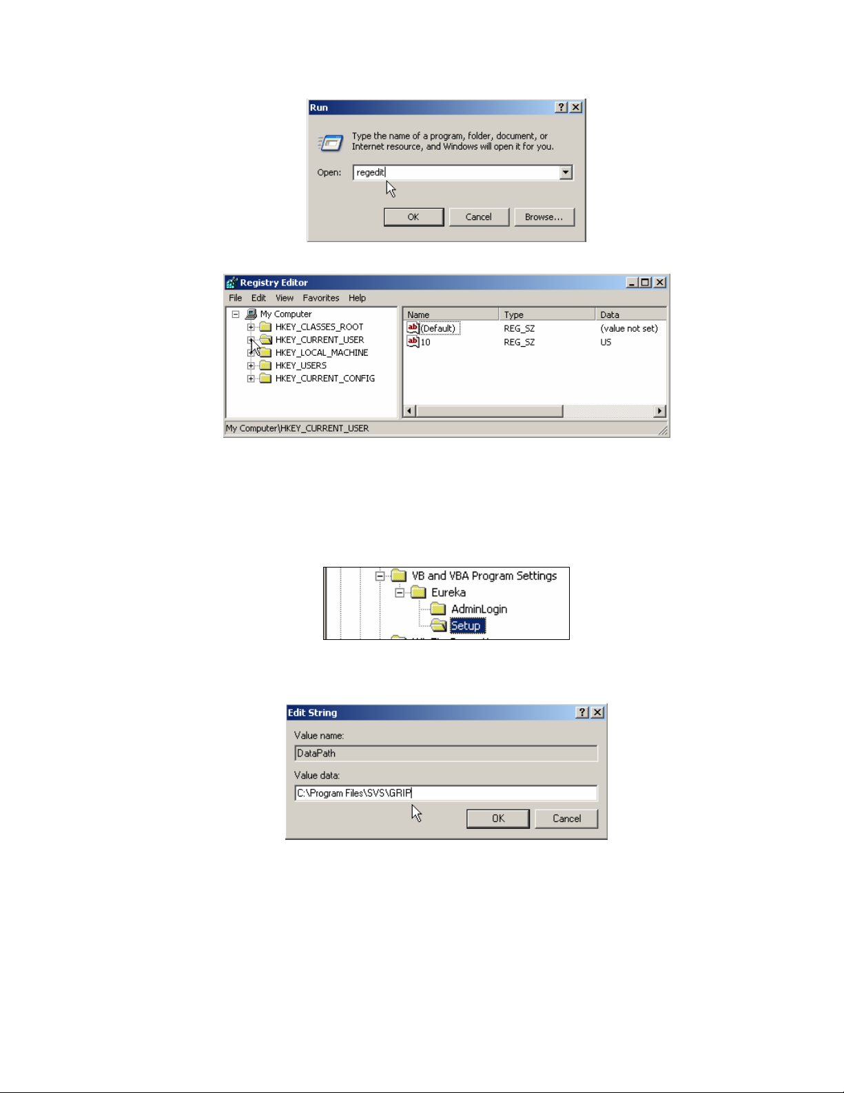
you have installed. This can be corrected by editing the data path in the PC’s registry.
First, select “Run” from the start menu and type “regedit” in the window.
3
Page 10
Sierra Video Systems
Select “OK”. The Registry Editor will open.
Click on the “+” next to HKEY_CURRENT_USER.
Click on the “+” next to Software.
Click on the “+” next to VB and VBA Program Settings.
Click on the “+” next to Eureka.
Click on the folder “Setup”.
In the window on the right, locate “DataPath” in the Name column. If the datapath shown
on the right (in the Data column) does not say C:\Program Files\SVS\GRIP, double click
on the ICON next to “DataPath” and the correct path in the Value data window.
4
Page 11

GRIP 3.1.0
PC Com Port Connection
SVS routing switchers are shipped from the factory with the baud rate set at 9600 Baud.
The Serial cable should be installed into the “Host” port on the back of the switcher and
Com Port 1 on the PC.
The router’s processor is shipped from the factory with the default settings. Please see
the router’s manual for more information regarding processor dipswitch settings.
SVS routing switchers use only 3 pins of a standard 9 pin D serial cable. In most cases
an “off the shelf” one-to-one cable may be used. Refer to the router’s user’s guide for
correct serial connection on the router host port.
PC Serial Cable Connections
Pin RS-232
1 Not Used
2 Transmit
3 Receive
4 Not Used
5 Ground
6 Not Used
7 Not Used
8 Not Used
9 Not Used
Note:
Some versions of Windows do not allow GRIP to turn off the function of pin 8 on your PC. It may
be necessary to remove pin 8 from the serial cable in order for GRIP to perform adequately.
If pin 8 is an issue, the following message will display;
Cabling problem with Pin 8 RS232, please check cabling, exiting Grip & switching to
AutoBaud Check.
* On the computer side, only pins 2, 3, and 5 are used.
5
Page 12

Page 13
Sierra Video Systems
Chapter
3
Router Setup
Starting for the first time
Double click on the GRIP icon. The program will start.
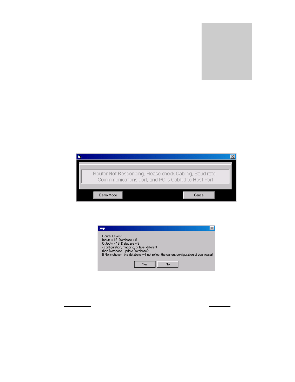
If the following message appears, and your PC cabling is correct, click on “Demo Mode”
and proceed to the Communications Setup section of this manual before continuing.
If the communications setups and serial cable wiring are correct, upon startup, this
Message Box may be displayed:
This message will only appear if the database in GRIP differs from the configuration of
the router.
This dialog box will be displayed for each level of the switching system.
*Warning; If you choose “NO”, the GRIP database will not reflect
the current configuration of your router!
Only select “NO” if you are sure that your router is incorrectly
configured. Proceed to the “Utilities” section to configure your
router. Do not attempt to re-configure your router without
factory assistance.
7
Page 14

Sierra Video Systems
New Systems
The GRIP database contains default settings and must be updated to reflect the size of
you router. You must say “Yes” to the message box so that the GRIP database will reflect
the current size of your router.
If your routing switcher is new, it has the default setup as you ordered unless we have
made other arrangements. Select “Yes” to the message box, the database in G.R.I.P. will
be updated to reflect the current system configuration.
If the routing switcher is currently installed in an operating facility, by selecting “Yes” to
the message box, the database in G.R.I.P. will be updated to reflect the current system
configuration; the settings in the database will be overwritten.
Routing switchers with software version 5.07 or later will update the database with all
routing switcher details including partially stuffed switchers with “Offsets” and/or mapped
systems.
Note:
To verify the database in GRIP matches the information in the router, close GRIP and re-open it
again. When the database is correct and the communication settings are correct, there will be no
messages and the program’s “main screen” will be displayed.
If your router is correctly configured, and you selected “yes” to the message box, proceed to the
Names section.
Upgrades
If you are upgrading your router, such as adding a new level or expanding the I/O size,
select “NO” and proceed to the “Utilities” chapter of this manual.
8
Page 15
GRIP 3.1.0
Communications Setup
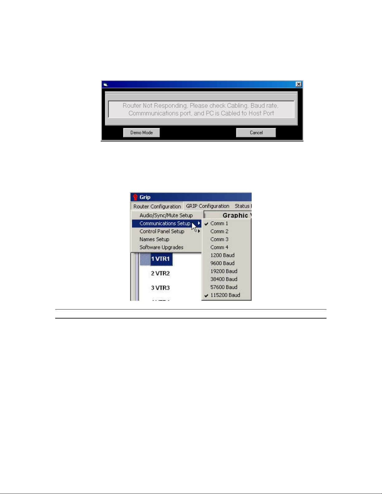
If the following message is displayed, you may need to set the communication
parameters of the software program to match the settings of the router
If the above message appears, click on “Demo Mode” and the program’s “main screen”
will appear.
Select “Communications Setup” in Router Configuration menu.
RS232 serial communications Baud rate and Com Port is selected in the following menu.
The factory default is Com 1, 9600 Baud.
.
Note:
*It is recommended that you set the router’s Host port baud rate and GRIP to 115200 Baud for
optimum performance. Otherwise operation of GRIP may be sluggish.
Be sure that the Baud rate matches the value set in your router. See your specific
router’s manual for details on setting the router’s Baud rate.
Any changes to these settings will cause a message to be displayed asking you to close
and reopen the program. This will initiate the changes.
Once communication has been established with the router and the Program’s database
concurs with the router settings, you may proceed.
9
Page 16
Sierra Video Systems
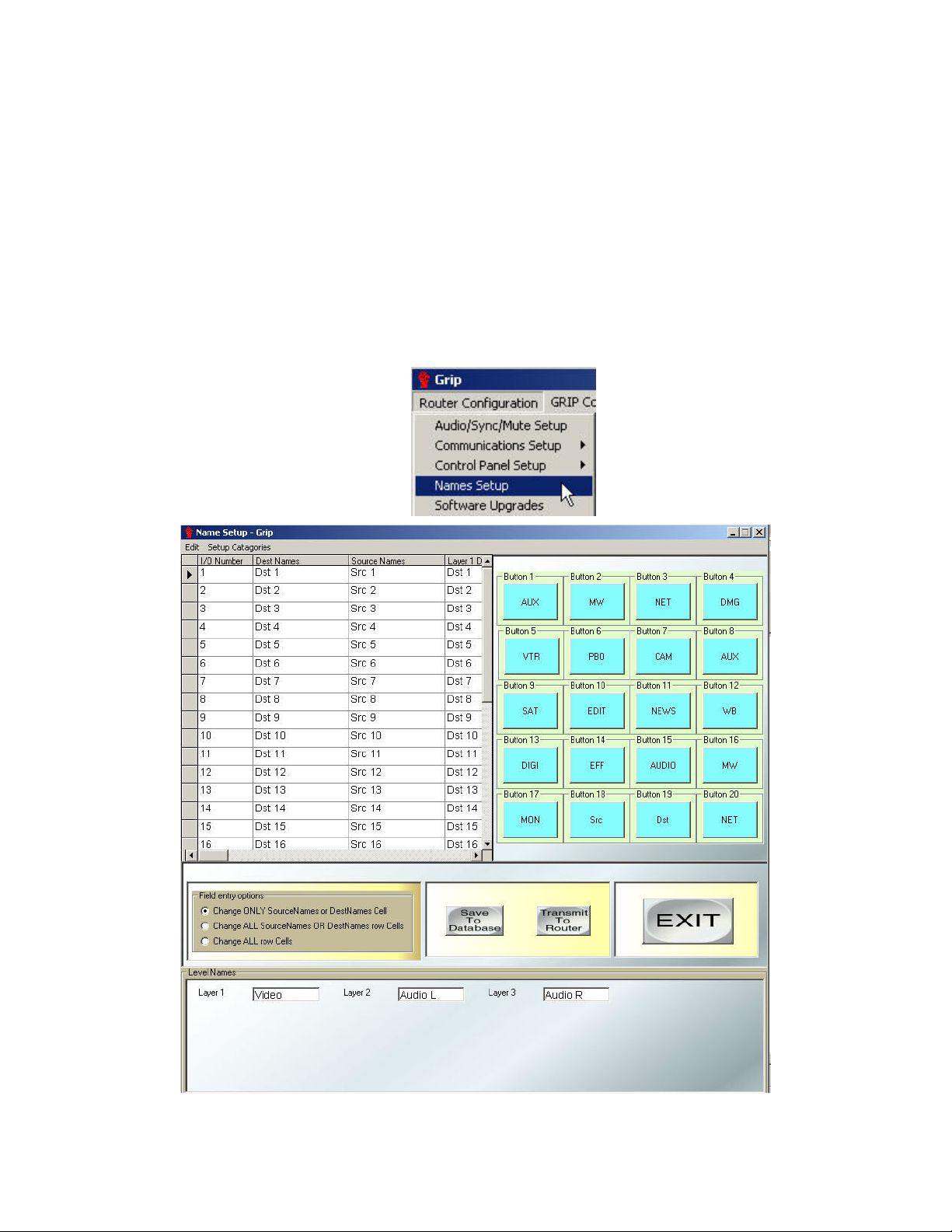
Names Setup
The program comes with default names “Src” and “Dst”. These names are not the names
stored in the router’s processor, they are the names in the GRIP database only. You may
want to change these names to meet your needs.
Names in the GRIP program consist of a prefix and suffix, such as VTR 1. VTR (short for
video tape recorder) as the prefix with the number 1 as the suffix. All VTRs would have
the same prefix (VTR) with a different suffix for each video tape recorder.
This method allows you to categorize common inputs or outputs, making naming and
switching of inputs and outputs simpler with the programmable SCP series of remote
control panels.
Select “Names Setup” from the Router Configuration drop down menu.
10
Page 17
GRIP 3.1.0
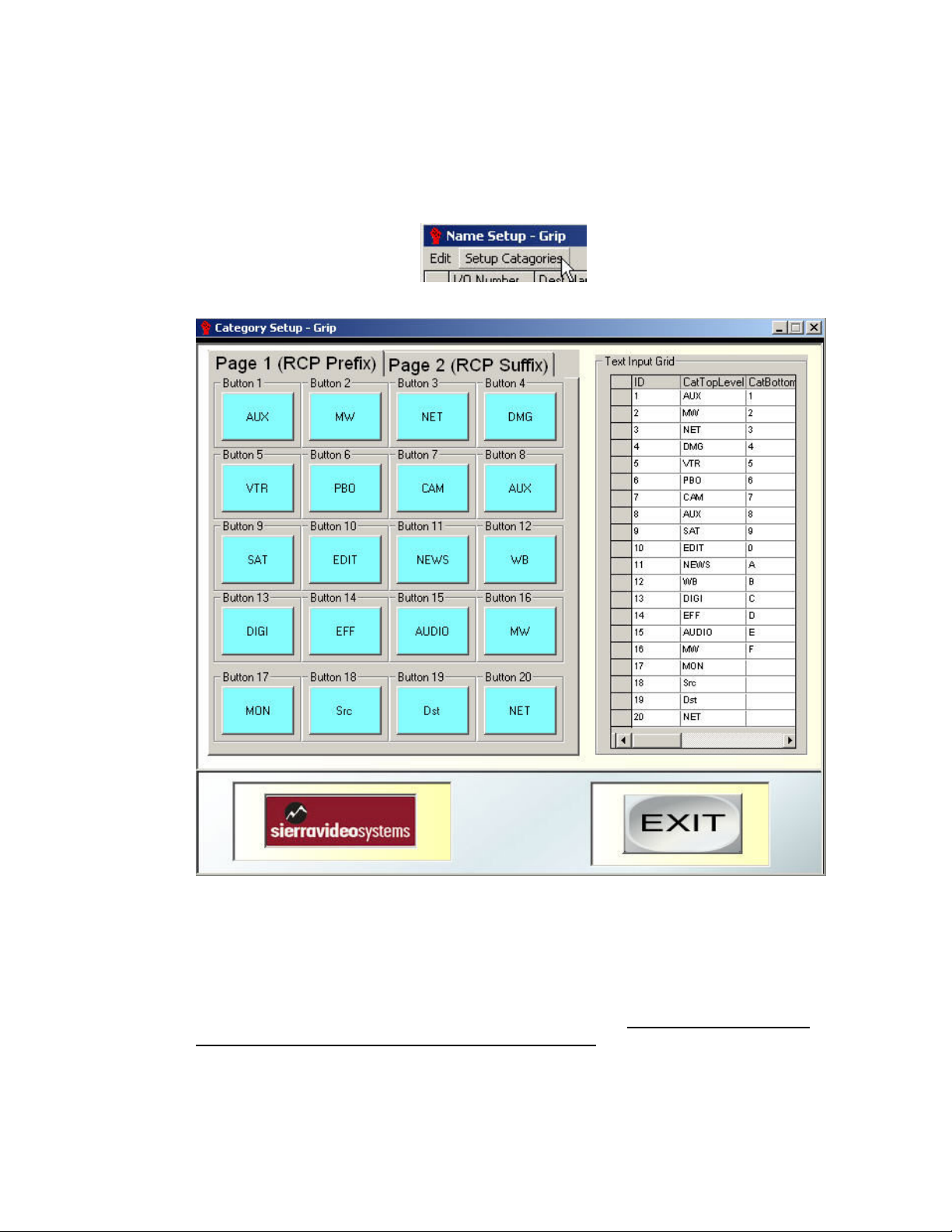
Category Setup
The first step in this process is to setup categories.
Categories are the user defined prefix and suffix.
Select “Category Setup” from the Names Setup screen menu:
The Following screen will be displayed:
This window creates and manages the Categories that are used in the Names window
and the Control Panel setup screen.
Two pages of 10 categories are available to be entered. Page 1 is for the Prefix; page 2
is for the Suffix. Select the button number to be entered in the text input grid and type the
name into the field. This utility is useful when naming Sources and Destinations in the
router. See “Names Setup.”
Entering new text in the excel-like display modifies categories. All changes are immediate
and are set in the Database upon any mouse or tab action.
11
Page 18
Sierra Video Systems
Names
After entering your prefix and suffix, you are ready to name the inputs and outputs. Exit
the Category Setup screen.
12
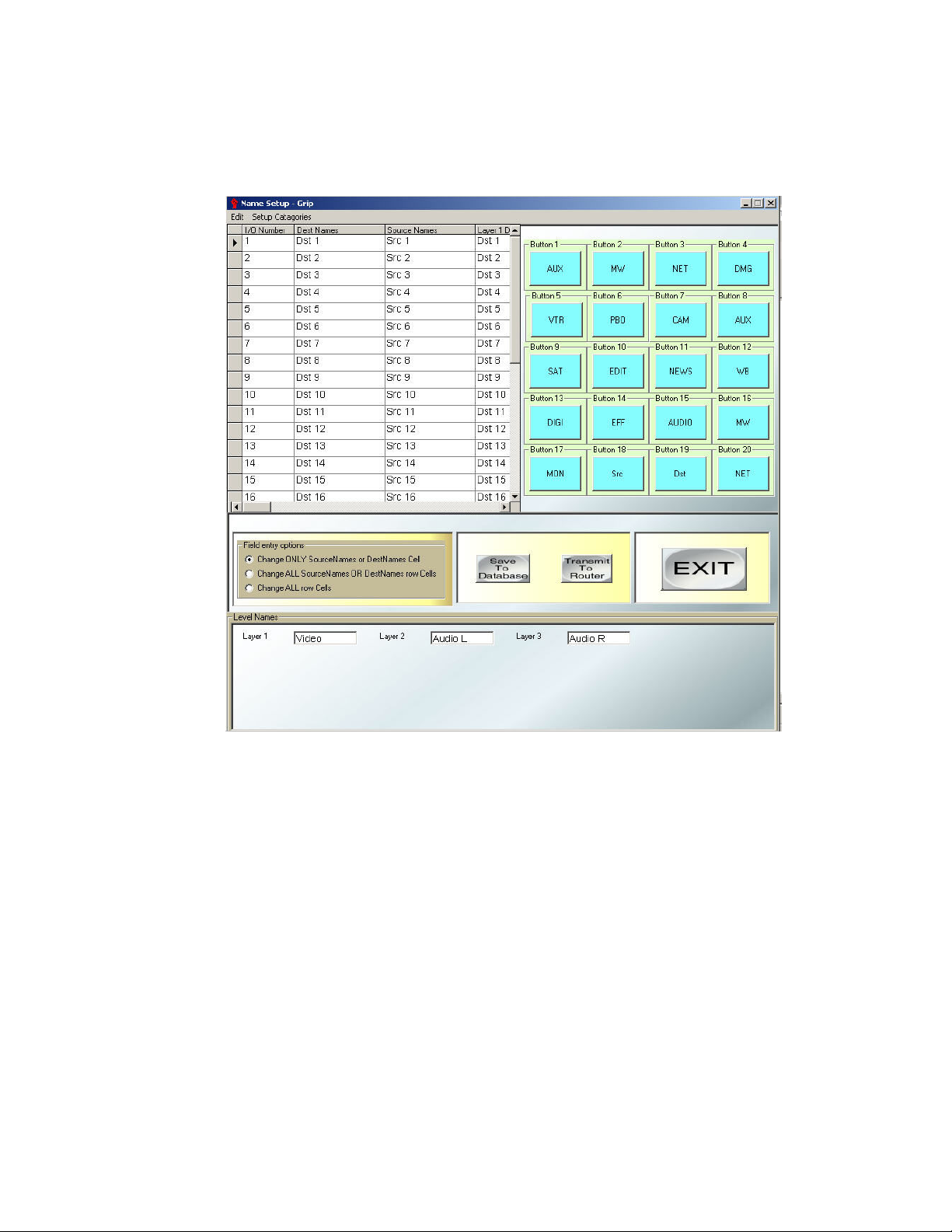
“Field Entry Options” determines how many fields in the spreadsheet get changed after
an entry. Normally all “Levels” of a source or destination have the same name with a
suffix added to the name, such as, VTR1 – (virtual) Dest Name, VTR1Aud R – (Level 2
VTR Audio Right), etc. The Field entry has the following three options:
Change ONLY Source (input) Names or Dest (output) Names Cell – this modifies only
the selected cell.
Change ALL Source Names OR Dest Names Cells – this modifies every other cell,
which corresponds to Sources OR Destinations.
Change ALL row Cells – this modifies every cell, which corresponds to both Sources
AND Destinations.
To enter a name, click on the name cell to be changed, highlighting the cell. Click on the
category button of the Prefix you want to use. The category buttons will change to page 2
allowing entry of a Suffix. Click on a Suffix button. The buttons will stay on page 2 until
you click on a different cell completing your name entry.
As an example, if you wanted to enter “VTR 11”, click on the cell to be named. Click on
the category button “VTR”. “VTR” will be entered in the selected cell. The buttons will
change to page 2. Click on The button programmed 1 twice. The cell should now display
“VTR 11”.
Page 19
GRIP 3.1.0
The names window is an Excel type display for easy alphanumeric name entry.
Downloading names to a large routing switcher can take up to a couple of minutes,
depending on the switcher size. A status bar with a cancel button is displayed as
downloading begins. All downloads are happening in the background mode in the routing
switcher, with routing given the highest priority, hence adding delays to the name
download.
This window has the ability to accept a “Paste” from an Excel spreadsheet.
Enter the Dst (Destination), Src (Source), and level names.
“Save to Database” Saves the names to the GRIP database only (This is for working
offline”.
“Transmit to Router” Sends the names to the router’s processor and saves the
information to the GRIP database.
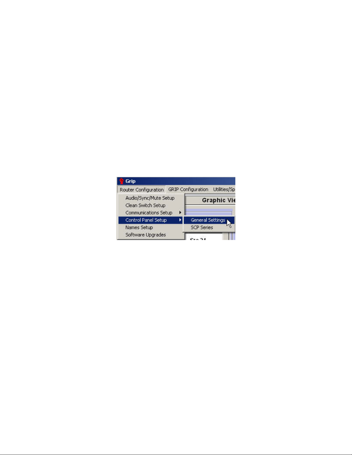
Control Panel Settings – General Settings
This section applies to all control panels using RS-485 (3 pin mini XLR connector)
communication.
Clicking on the “Control Panel Setup/ General Settings” displays the following window
and causes G.R.I.P. to poll the routing switcher for all panels, which are connected on the
SVS control panel bus.
13
Page 20
Sierra Video Systems
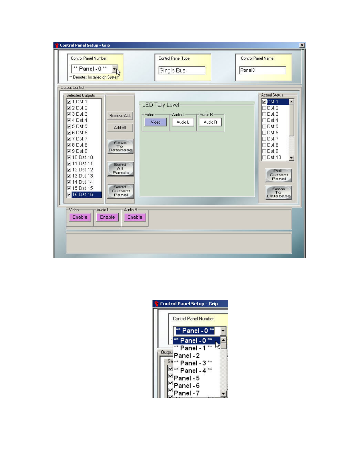
The “Control Panel Setup” window sets and reads the control panel settings of the routing
switcher. Under the “Control Panel Number” list, ** denotes panels detected on the
system.
Select the panel ID number for the panel whose status you want to view.
By pressing the “Poll Current Panel” button, G.R.I.P. sends to the routing switcher a
request for panel output and level control status of the currently selected panel.
14
Page 21

GRIP 3.1.0
Outputs that are enabled are displayed in the “Actual Panel Status” window. The Level
“Enable/Disable” buttons show and set the levels a panel will control.
If a box is checked in the “Actual Panel Status” window, this means the selected panel
can control the “Checked” output. To block or un-block an output, click on the box next
the output(s) listed in the Selected Outputs window.
“Remove All” removes all check marks from the Selected Outputs window.
“Add All” adds checks destinations in the Selected Outputs window.
The Output Control window sends the selected outputs to be controlled, to the panel
(when “Send Current Panel” is pressed).
The Actual Status window displays the current outputs that are controlled by the selected
panel.
All SVS control panels can have outputs blocked, this allows the control panel to status
an output, but prevents the panel from selecting inputs on that output.
15
Page 22

Sierra Video Systems
The “LED Tally Level” selects which level a non SCP Pushbutton panel’s lamps will
follow.
The Level buttons select which levels the panel will control.
Example; If the panel is to be a Video Only control panel, Disable all levels other than the
Video level. When the panel is switched, only the Video level will change.
If the routing switcher and panel have been previously programmed and the setup needs
to be saved to the database, click on the “Save to Database” button.
If changes are made to this screen, The panel can be named to indicate location if
desired.
“Save to Database” saves the data in G.R.I.P. but not to the routing switcher or the
control panel.
“Send Current Panel” downloads the current panel that is selected in the “Control
Panel Number” frame.
16
The “Send All Panels” button downloads ALL the setups for ALL 64 control panels to
the routing switcher.
After sending the Control Panel setup, press “Poll Current Selected Panel” to verify
your settings before closing the window.
Page 23

GRIP 3.1.0
SCP Series Setup (Other than the SCP-200)
The SCP line of control panels requires switcher software version 7.01 or newer for
programming compatibility.
We begin with a brief discussion on the SCP panel’s programmability concepts. These
panels were designed to allow for maximum flexibility in the categorization of buttons. A
button can have multiple functions depending how it is programmed and where the user
is in the sequence of pushes. As an example, the first push on a Button could write “VTR”
on the display. The second push on the same button could add a “1” to “VTR” as a suffix
so we would see “VTR1” on the display. If another number programmed button were
pushed, such as a 3, we could see “VTR13” on the display. The Second Push row would
remain enabled until the “Shift”, “Clear”, or the “Take” button were selected and would
force the panel into a different set of actions.
The Shift Push is similar to the Ctrl key on the PC, which allows different functions to be
performed on the panel, such as toggling between “Alpha” and “Sort” on numerical values
during a scroll function. All Buttons in the SCP line of control panels are soft key. That is,
every key can be programmed. As an example, the SCP-112 can become a 12-button
salvo panel, or only a 6 destinations and 6 sources control panel.
17
Page 24

Sierra Video Systems
Programming a SCP series panel
This section contains general programming information. For detailed SCP panel
programming instructions, see the specific SCP panel’s manual.
Set desired output and level control in the “General Settings” window.
Select “Control Panel Setup/ SCP Series” from the Router Configuration menu.
The following screen will be displayed:
The SCP-112 programming screen will come up as a default until you select the specific
panel you want to program. After pressing Save or Send, GRIP will remember the panel
type according to the ID number.
18
To select the panel you want to program, click on the Control Panel Number List box.
Active panels are denoted by ** before and after the panel address as shown below.
Select the panel you want to program from the list.
Select the tab to reflect the type of panel chosen.
Page 25

GRIP 3.1.0
To program a button, click on a List box, which displays a dropdown list as shown:
There are several lists that group function types.
Select a function by moving the list to the desired function and clicking on the function.
G.R.I.P. puts this selection in the Drag Drop mode so you can now drag the function to
the button that is desired on the Special Push, First Push, and Shift Push rows.
A detailed list of functions can be found in the SCP panel manuals.
19
Page 26

Sierra Video Systems
Panel Properties
By clicking on the “Panel Properties” tab the following screen will be displayed:
Note:
This screen applies operator preferences to the selected panel.
The “Special Push” function is not available on all SCP control panels. The “Special
Push” enable box will be inactive for panels which do not support this function.
*If “Special Push” is enabled, the action of this button becomes the first push command
with the “First Push” row of buttons becoming the subsequent commands until Take,
Select, or Clear is pushed.
When you have finished the configuration, save the information to the database by
clicking on the “Save” button. You may “Send Current” panel configuration or, after
saving the panel setup, select another panel to program.
“Save” the information to the G.R.I.P. database after configuring each panel. “Send All”
will send configuration data for all of the panels to the Router and control panels.
Refer to the SCP panel manual for details of setup.
20
Page 27

GRIP 3.1.0
Audio Gain Setup
Some models of SVS routers have the option to adjust audio gains using GRIP. If your
router has this option, the following section describes the steps necessary to adjust audio
gains.
Select “Audio/Sync/Mute Setup”, from the Router Configuration menu:
The following screen will be displayed:
This is a multi function screen. The following section describes setting audio gains of the
router’s individual inputs and outputs.
Note:
This screen is also used to set Video delay (muting) and sync rate.
21
Page 28

Sierra Video Systems
Adjusting Audio Gain
Enable the screen to adjust audio gain by clicking in the box next to Gain on the right
hand side of the screen:
22
To adjust gain, move the mouse pointer over the fader corresponding the input or output
you want to adjust. Holding down the left click button on the mouse enables you to adjust
the fader.
Holding down the left click button on the mouse also enables you to adjust the fader
using the up/down arrows on your keyboard.
Set the input and output gains to meet your requirements.
Page 29

GRIP 3.1.0
“Poll Router” polls the router for current settings.
“Transmit to router” will send your settings to the router.
“Save to Database” stores your settings in the GRIP database.
“Get from Database” will retrieve the settings stored in the database.
“Set 0dB Gain” will cause all inputs and outputs to return to a unity gain (0db) setting.
“1-16” and “17-32” will cause the screen to display the inputs and outputs 1 through 16 or
17 through 32 for larger routers.
Placing a check in the “Update Router Instantly” box will cause the router to change
settings as you move the fader. This will not cause the information to be stored in the
database. You must press “Save to Database” to store your settings.
A/V Delay
Some models of SVS routers have the ability to adjust A/V delay using GRIP. If your
router has this option, the following section describes the steps necessary to adjust A/V
delay.
A/V muting (delay) is a function that “delays” the video and audio signal of an output for a
“user adjustable” amount of time after a “take” command is sent to the processor. The
sync signals will be immediately upon the “take” command; only the video and audio will
be delayed.
To adjust A/V delay, select Audio/Sync/Mute Setup from the Router Configuration menu
(this is a multi function screen):
Place a check in the Delay box:
23
Page 30

Sierra Video Systems
The following screen will be displayed:
The faders will adjust the delay (muting) time for their corresponding output. The delay
time has an adjustable range from 0 to 10 seconds in .5 second increments.
A “tool tag” will appear indicating the delay setting.
Set output delays to meet your requirements.
“Poll Router” polls the router for current settings.
“Transmit to router” will send your settings to the router.
“Save to Database” stores your settings in the Routing Software program.
“Get from Database” will retrieve the settings stored in the database.
“Set At Unity Gain” has no function in the “delay” mode.
“1-16” and “17-32” will cause the screen to display the outputs 1 through 16 or 17
through 32 for larger routers.
Placing a check in the “Update Router Instantly” box will cause the router to change
settings as you move the fader. This will not cause the information to be stored in the
database. You must press “Save to Database” to store your settings.
24
Page 31

GRIP 3.1.0
Sync Rate Reporting
Some models of SVS routers have the ability to report sync rate using GRIP. If your
router has this option, the following section describes the steps necessary to report sync
rate.
To access the Sync Rate reporting screen, select Audio/Sync/Mute Setup from the
Router Configuration menu:
Place a check in the Sync Rate box of the sync channel you want to measure:
Or
25
Page 32

Sierra Video Systems
The screen will change to the following:
The sync frequencies present on the input H or V channels will be displayed next to the
corresponding input number.
Sync Termination
Some models of SVS routers have the ability to select sync channel input termination
using GRIP. If your router has this option, the following section describes the steps
necessary to report sync rate.
To access the Sync Termination screen, select Audio/Sync/Mute Setup from the Router
Configuration menu:
26
Page 33

GRIP 3.1.0
Place a check in the box of the sync channel you want to set:
or
The screen will change to the following:
Using the faders, the sync termination can be changed to 75ohms or 510ohms.
“Poll Router” polls the router for current settings.
“Transmit to router” will send your settings to the router.
“Save to Database” stores your settings in the GRIP database only.
“Get from Database” will retrieve the settings stored in the database.
“Set At Unity Gain” has no function in the “delay” mode.
27
Page 34

Sierra Video Systems
Software Upgrades
From time to time software upgrades will be available from SVS. Check our web site
sierravideo.com for available downloads, or contact the factory.
Before you start
If you are upgrading router software, be certain that the database reflects the
configuration of your router (i.e. names, router size, ect.). Upgrading software can cause
your router to lose information previously stored in the processor. When the upgrade is
complete you must resend the router’s configuration that is stored in the database (see
below).
Upgrading software can take several minutes at slower baud rates. For a quicker
download time change the router and the Router Software to a faster baud rate.
Download the software upgrade to a folder on your PC. Open the GRIP program and
click on “Router Configuration” from the drop down list, select “Software upgrades”.
The following window will be displayed;
28
Page 35

GRIP 3.1.0
Control panel upgrades
Active panels will show with a panel part number after the panel ID. Click on the box next
to the panel to be upgraded. Click on “Select File and Send”. A Windows’ open box will
appear. Select the file you have downloaded and click on open. The file will be sent to the
panel you have selected.
Router Upgrades
Click on Router Upgrade, placing a check in the box. Click on “Select File and Send”. A
Windows’ open box will appear. Select the file you have downloaded and click on open.
The file will be sent to the router’s processor.
Important; After the software download, the router’s processor may return to the factory
default (9600). Be certain that the baud rate of the router and the Router Software
program are set the same before continuing.
After the download is complete click on the Restore Router button to send the
configurations stored in the database to the router’s processor.
The router will reset the router when done.
29
Page 36

Page 37

Sierra Video Systems
Chapter
4
GRIP
Configuration
The GRIP Configuration dropdown menu contains functions that effect the operation of
the GRIP program. The Group Setup option sets up “groups” of inputs and outputs that
are accessible to some models of SVS routers but is always accessible to GRIP.
Database Management
After setting up your router, we recommend you save a copy of the database in a “safe”
location, or medium, in case of PC failure.
Select “Database Management” from the configuration menu;
The following screen will be displayed;
31
Page 38

Sierra Video Systems
To save a copy of the current database, press “Save Copy of Database”. A windows
“Save As” screen will open:
The “Save As” screen will open to the current location of the GRIP database. The current
database will always be named Eureka.mdb. You may re-name the database to any
name you choose, and select the location to store the copy.
32
To retrieve a saved database, open the Database Management screen and press “Select
New Database”. A windows “Open” screen will open:
Page 39

GRIP 3.1.0
Navigate to the location of your saved database, select it, and press “Open”.
You will be prompted to exit GRIP and re-open. After exiting and re-opening GRIP the
new database will be installed.
Options
A checkmark in front of any option means that this option is selected.
“Enable Router Polling” GRIP updates router status every time a switch is made and
whenever a destination is highlighted. Checking this option causes G.R.I.P. to ask for a
destination status every 15 seconds. GRIP will update the “Status Display” with current
routing switcher crosspoint status.
“Double Click Takes” tells G.R.I.P. to instantly take a doubled clicked source if a
“Destination” in the “Status” window is selected. This option is effected for only the
selected destination.
“Graphic View- 1 to All Enable” When this option is selected and you are in the
Graphic View screen, selecting a source will cause the selected source to be sent to all
outputs. This is a troubling shooting operation and should not be selected for normal
operation.
33
Page 40

Sierra Video Systems
“Show Groups” displays the Group Tabs most often used for room grouping. There is
no limit on the number of groups, but the tabs will no longer display names at some point.
“Physical I/O Number in Lists” displays a number corresponding to the order of the
table in the Status, Source, and Preset windows. This option is handy for troubling
shooting and initial setup.
“Press Take for a Salvo Take” tells G.R.I.P. whether to instantly send a Salvo Take
command or wait for the user to click on the “Salvo Take” button.
“Display Salvo” displays the Tabs and Salvos when checked or hides them
(unchecked).
“SCP Setup Classic” Displays alternate setup screen in SCP control panel setup.
“Classic” setup screen resembles SCP setup screen in earlier versions of GRIP.
“Large Graphics” Changes display size on Graphic View Screen.
“Version 7 and Newer Router Code” Newer versions of router software is capable of
sending data faster than older versions. The factory default is set to version 7 or newer. If
you are running this program on an older router, version 7.0 or older, disable this option.
34
Page 41

GRIP 3.1.0
Group Setup
Overview
Room Groupings are groups of user defined inputs and outputs. If your router is being
switched from several locations (rooms), you may want to restrict the inputs and/or
outputs controlled by each location.
As an example, your router is being switched from two locations, a boardroom and a
conference room and the boardroom uses different outputs and inputs than the
conference room. To prevent accidental switching of the boardroom outputs or inputs
from the conference room or vice versa, you can restrict the ability of input and output
control of each location by setting up “rooms”.
You can also restrict the “level” the room can switch. If you have a video (level 1) and a
audio level (level 2) for a given input, but only the boardroom to switch the audio (level 2),
you can restrict the ability of the boardroom so that only the audio of that input is
switched from that room group.
Select “Group Setup” in GRIP Configuration menu:
The Following screen will be displayed:
The Group Setup screen was designed for room groupings, that is, it only displays a
“user defined” number of Sources and Destinations with an AFV (all levels), single level,
or multi level group. Clicking on the Tab with the desired group name will fill the List
boxes with the sources, destinations, and levels from the database, for that group.
Double clicking on a Destination in the “Destination” List box causes G.R.I.P. to add the
selected destination to the “Destinations” List box. This also can be accomplished with
the Selected/Current Sources List box by using the feature of ALL levels or only selected
levels. Levels are selected or deselected by clicking on the level button.
35
Page 42

Sierra Video Systems
A Group can be renamed by typing in new text in the Textbox named “Group Name”.
Clicking the “Save Group” button will save the group name and all selected sources,
destinations and level configurations.
Configure Room Groups to meet your requirements.
“Save Group” will save the selected Group to the database.
“Delete Group” removes selected Group from the database.
“Add Group” adds a new Group to the tab at the top of the Group Setup screen.
“AFV” selects all levels.
“Send Room Groups” stores Group configurations to the router.
36
Page 43

Sierra Video Systems
Chapter
5
Operation
Introduction
Main Screen
The following is the GRIP Main Screen. Select the Main Screen tab at the top of the
window. ToolTips have been used extensively throughout the software and by holding the
mouse over most functions/buttons/windows; a tool tip will pop up after a few seconds.
37
Page 44

Sierra Video Systems
By clicking on a “Destination” in the “Status” window, G.R.I.P. will send a command to
Poll the routing switcher and place the status in the status window along with all level
status shown in the textboxes in the Level windows (Labeled “Lvl 1”). By double clicking
on a Destination in the status window, the destination is added to a “List” in the Preset
window. This preset can be left in the preset window as long as desired. While selected
in the preset window, Sources and Source levels can change on that destination until it is
cleared from the Preset Window. Double clicking on an item in the preset window deletes
the line. Clicking on “Clear”, clears all entries in the Preset Window.
By using the Mouse click while holding down the Ctrl key or the Shift key, multiple
destinations can be selected. Pressing on the “>>” button located in the “Sources” Frame
moves all selected Destinations into the preset window. Selecting a Source and Pressing
the “Send to all Dests” sends the selected Source to ALL Destinations in the preset
window. This also can be accomplished by pressing the “A” key on the PC Keyboard.
Clicking on a Destination in the Preset window selects a Destination that can be modified
with a different source or a single level source. A single level source change is
sometimes called a “Breakaway” while an all level change is sometimes call an Audio
Follow Video or “AFV” switch.
By selecting a Group Tab, the Destination and Source windows fill in specific Destination,
Sources, and Levels, which are defined in the Group Setup window (see the “Room
Grouping section of this manual).
Graphic View
Select the Graphic View tab at the top of the window. The following screen will display;
38
The Graphic View window displays the status of all I/Os. I/Os can be switched from this
screen by clicking on the source button on the desired destination row.
Levels can be selected for “break-away” by clicking on the appropriate level buttons at
the bottom of the screen.
Page 45

GRIP 3.1.0
Alternate switching method
The router can also be switched by selecting “Routing + Salvos” from the menu.
• Select the level(s) you want to change.
• Select the destination.
• Select the Source.
• Select “Take Route” to make the switch.
Stored Salvos can also be switched from this menu. Select the salvo from the drop
down menu and “Take” (see the Salvo section of this manual for Salvo details).
Status Router
Clicking on “Status Router” will cause GRIP to request all I/O data from the router and
update the Destination information in the Status column.
Salvos
Overview
A Salvo is a list of crosspoint switches that are downloaded to the routing switcher and
switched by a single “Salvo Take” command.
GRIP Software allows up to 40 Salvos to be named and stored in the routing switcher.
The program is limited to 160 takes per salvo.
Salvo Setup
To program a salvo, enter the desired Destination/Source combinations in the preset
window and click on the “Save Salvo” Button. All salvo buttons begin to flash between red
and light blue, indicating a selection must be made. If a name is desired, type the name
into the “Salvo Name” Textbox in the lower right hand corner of the window. Click on the
desired flashing salvo button. The newly entered name is displayed on the salvo button,
the button stops flashing and the salvo is stored in the routing switcher and available to
all control points of the routing system.
39
Page 46

Sierra Video Systems
To exit the “Save Salvo” mode without saving, click on the “Clear” button.
The salvo name will be displayed in most control panels. For example, Salvo 1 in the
example below is named “1 to 1”. This name will appear in all control panels capable of
executing the “Salvo Take” command.
40
Page 47

GRIP 3.1.0
When “Press Take for a Salvo Take” is checked in the Configuration/ Options menu, the
Salvo “list” will be displayed in the Preset window, and will remain after “Take Salvo” is
pressed. Press “Clear” to clear the Preset window.
41
Page 48

Sierra Video Systems
Locks
You may want to “Lock” a destination in order to prevent someone on the system from
changing the source from another location.
By selecting a Destination in the Status Window and clicking on the “Lock” button, an
individual selection will be locked which will be signified by a flashing lock (unlock) button
and a Red and Black “L” displayed in the Status window. The “Lock” button changes to
“Unlock”. To unlock a Destination, select the “Locked” Destination and press the “Unlock”
button. The button will change back to normal.
42
Page 49

Sierra Video Systems
Chapter
6
Utilities
Introduction
The utilities screen is for changing the size configuration of your router to be different
from the factory configuration as ordered. This would apply if you are adding levels or
expanding the size of your router. This should only be done with factory instructions.
To access the utilities/special functions menus, press Ctrl/Shift/U on the PC keyboard.
The item “Utilities/Special Functions” will appear on the menu bar. Select “Utilities” from
the drop down list.
The following screen will display:
43
Page 50

Sierra Video Systems
Router Setup
If your router is configured incorrectly, and you have selected “No” to the message box,
continue with this section to configure your router.
Note:
Do not attempt re-configuration of your router without factory assistance.
Select “Utilities” from the “File” drop down menu.
The Following screen will be displayed:
44
Page 51

GRIP 3.1.0
G.R.I.P. can control up to 16 levels of a switching system. The example above shows a
routing switcher that has three layers, a 16 x 16 video level with two levels of 16x16
audio.
To add or remove a layer, click on the “Level Enabled/Disabled” Button. Select “Router
Type,” from the drop down list. Enter the actual size of the routing switcher in the
“Number of Destinations” and “Number of Sources” text boxes. A partially stuffed routing
switcher should have the actual number of destinations and sources. For example, a
64x64 Yosemite analog video routing switcher stuffed to 32 inputs and 32 outputs, “32”
should be typed in each of the text boxes.
A Partially stuffed Yosemite routing switcher or a mapped routing switcher can be setup
and initialized using this window. Select the frame size and I/O type of each layer of your
router.
The routing switcher must be reset after a download for all the changes to take effect.
Caution, if frame size and mapping information are changed, the routing switcher will
make routing changes during a download, so do not download during facility operations.
The router can be reset from the “Special Functions” menu. (See below).
When this screen is completed;
“Save to Database” stores your settings in the GRIP database only.
“Send to Router” saves the information in the GRIP database and sends the information
to the router’s processor.
“Reset All” resets the GRIP database to the GRIP default settings (not the router’s
default settings).
Note:
The router must be reset to initiate the changes.
Click on “Router Reset” in the “Special Functions” menu and reset the router to initiate the
changes in the router’s processor. The router can also be reset by turning power off and turning
on again.
Special Functions
Menu items include Sequoia Setup, PIK Software Upgrades, and a Router Reset
function.
Before making any changes in these screens, we advise you to call the factory for proper
configuration settings.
45
Page 52

Sierra Video Systems
Sequoia Setup
If you have a Sequoia Router and you need to change the configuration, use the
following screens.
Before making changes using the Sequoia Setup window, we advise you to call the
factory for proper configuration settings. The factory will send a configuration file to you.
Download this file to a folder your PC.
Select Sequoia Setup from the Special Functions menu:
The following screen will be displayed:
Click on “Select File and Send”. A Windows’ open box will be displayed. Select the file
you have downloaded and click on open. The file will be sent to the router’s processor.
Reset the router when done.
PIK Software Upgrades
PIK software is the program used in Sequoia Router’s PC boards.
Do not attempt this without factory assistance
download to your PC.
Select PIK Software Upgrades from the Special Functions menu in the Router Setup
screen:
46
. The factory will send you a file to
Page 53

GRIP 3.1.0
The following screen will be displayed:
Select the type of Card you want to upgrade. Press “Select Hex File and Send”. A
Windows’ open box will appear. Select the file you have downloaded and click on open.
The file will be sent to the selected card.
47
Page 54

Page 55

Sierra Video Systems
Chapter
7
Virtual Mapping
Introduction
Sierra Video Systems routers are shipped configured as “linear mapped”. That is, all
levels switch at the same time when an I/O is selected.
The term one-to-one mapping, or linear mapping, means that source 1 is assigned to
physical input connector 1, source 2 to connector 2, etc. This is the default mapping that
is shipped with each Sierra router. If one-to-one mapping is adequate, you do not need
to follow the instructions in this section for setting the mapping tables.
In non-mapped (linear mapped) Sierra routers, when a control panel or control program
calls for a connection, or “take”, from source 3 to destination 18, this means that the
signal going to the physical input connector labeled “3” is to be connected to the physical
output connector labeled “18”.
Sierra Video Systems routers offer the option of “Virtual Mapping”. In virtual-mapped
Sierra routers, a mapping table stands between the control panel “take” request, and the
physical connectors that are switched. Its purpose is to give the user more flexibility in the
way signals are connected to the router, and the way numbers are assigned to the
signals by the router.
There are two mapping tables, one for sources and one for destinations. Each mapping
table simply assigns a physical connector number to each source or destination number.
To help keep things straight, Sierra uses the following nomenclature when discussing
virtual mapping. The term source means a source number called for by a control panel or
control program doing a “take”. Likewise, the term destination means a destination
number called for by a control panel or control program doing a “take”.
The term input is reserved to mean a physical input connector on the router frame.
Likewise, the term output means a physical output connector on the router frame.
The source mapping table simply assigns, for each source number on each level, a
physical input connector number on that level. And likewise, the destination mapping
table assigns, for each destination number on each level, a physical output connector
number on that level.
49
Page 56

Sierra Video Systems
For example, the mapping table could be set to assign physical input connector 39 to
source number 1 on level 1. If so, then when a control panel requests a “take” of source 1
on level 1, it will be the signal connected to physical connector 39 that actually gets
routed.
It is also possible to set a mapping table entry to unmapped, meaning that that source or
destination on that level does not map to any physical connector, and therefore a take of
that source or destination will have no effect.
The term multiple mapping refers to mapping more than one source to the same physical
connector. Multiple mapping is not permitted with destinations
example, it is possible to map sources 3 and 98 both to physical input connector 20.
Multiple mapping can sometimes lead to confusion, especially when viewing status
displays on some control panels, so it is advisable to avoid it. However, some customers
can use it to great advantage.
In order to make it easier for users to work with large routers containing many sources
and destinations, Sierra routers support the assignment of alphanumeric names to
sources, destinations, inputs, and outputs. Control panels and control programs can use
these names to display router crosspoint status and to allow the user to compose “takes”.
Source and destination names (virtual names) apply to all levels. That is, you cannot give
different names to a given source on each level. You can only give it a single name that
must apply to all levels. Think of (virtual) source names as names given to source
numbers, and think of (virtual) destination names as names given to destination numbers.
Input and output names may be different on each level. That is, an input may be given
one name on level 1, and an entirely different name on level 2. Think of input names as
names given to input connectors, and output names as names given to output
connectors.
, only with sources. For
Often, an input’s name will be the same on all levels, and likewise for an output’s name.
Furthermore, it will often be the case that a source’s name will be the same as the name
of the input it is mapped to, and likewise for destination names. However, it’s your choice.
A user typically controls a routing switcher by using a control panel to enter and view
destination, source, input and output names and numbers. Below is a summery of the
typical process a user would go through to examine and take a destination using a
control panel:
1. Destinations are shown and selected by the user using the destination name and/or the
destination number. The physical output number that the destination maps to, or its name, is
not shown on the control panel.
2. The crosspoint status of a destination is usually shown using the physical input names and/or
numbers on each level. There are two reasons why the virtual source names/numbers are not
used: (a) source names apply to all levels, while input names can be different on each level,
and it is often important when displaying status to be able to see different names on each level;
(b) if multiple mapping is used, displaying the input name rather than the source name reduces
confusion by showing the actual physical signal name, which will be the same for two different
source names with multiple mapping. Because names are often the same on all levels, and the
same for a source and its mapped input, it will often be the case that if source names had been
displayed instead, they would be the same.
3. Some control panels allow the crosspoint status of a destination to be viewed using source
names and/or numbers rather than input names/numbers. The SCP series of control panels can
be set to show status in either form (source names or input names). It is user selectable when
programming the control panel using the SVS GRIP router control software.
4. Takes are composed by the user using either source or input names, or source numbers. A user
may enter either a source name or an input name or a source number for each level of the take
he is composing. An entered name is looked up in both the source and input name tables, to
locate the source number to use for the take. If the name is found in the input name table, the
50
Page 57

GRIP 3.1.0
first source that is mapped to that input is used. The behavior is slightly different depending on
whether he is composing an all-levels (AFV) take, or a breakaway take. If an all-levels take is
being composed, the name is first looked up in the source name table, and if not found, the
input name table is searched for the name. If a breakaway take is being composed, the search
order is just the opposite, with the input name table searched first, and then the source name
table. In many cases the search order would make no difference, because the same names are
used for source and its mapped input.
The number of sources and destinations in a Sierra virtual-mapped router can be configured
by the user. It can be many more than the physical size of the router, which can be useful in
different ways.
There are many uses for virtual mapping, such as:
1. Virtual sources can be mapped in such a way as to permit an all-levels take of that source to
accomplish what would previously have to have been done with a breakaway take. You could
map some virtual sources on all levels, while mapping others on only a few levels, and leaving
other levels unmapped. This permits doing all-level takes that affect only some levels.
2. You may wish to keep all the signals from one type of machine grouped together in the same
group of source or destination numbers, and yet you may want to have the flexibility to add
more of these signals at a later time without having to move a lot of signals from one connector
to another. Suppose that VTR1-VTR8 are assigned to input connectors 1-8, and CAM1CAM12 are assigned to input connectors 9-20. The mapping table is set up so that sources 1-8
are VTR1-VTR8, and sources 9-20 are CAM1-CAM12. Later on, you add VTR9, and you
want to make it be source 9, and make CAM1-CAM12 be sources 10-21. But at the same time
you do not want to have to move all the connectors CAM1-CAM12 down one. You could put
VTR9 on input connector 21, and map source 9 to input 21. You would have to change the
mapping of sources 10-21 so that they mapped to inputs 9-20.
3. In partially-stuffed routers with holes, mapping allows the holes to be “mapped away”, so that
control panels see one continuous set of sources or destinations.
4. Two separate levels can be “joined together” into one level, by mapping first one level, then
the other, to successive sources or destinations. For example, suppose you have two levels,
each 16x16. Sources 1-16 could be mapped to level 1 inputs 1-16 with level 2 unmapped.
Sources 17-32 could be mapped to level 2 inputs 1-16 with level 1 unmapped. Likewise for
destinations. You would not be able to connect source 1 to destination 17, for example, but you
could connect any source 1-16 to any destination 1-16, or any source 17-32 to any destination
17-32. You would not have to concern yourself with levels.
5. A more complete join of two levels could be done by cabling inputs of the two levels together.
For example, if you had a router with two 64x64 analog video levels, you could connect 64
inputs to the first level and then cable them in parallel to the second level also, so that both
levels received the same 64 inputs. Then, you could map destinations 1-64 to level 1 outputs
1-64, and destinations 65-128 to level 2 outputs 1-64. You would end up with a 64x128 singlelevel router.
6. One source could be mapped on all levels, while another one might be mapped only on audio
levels. The first would be used to set up all levels of a destination, while the second would be
used to change the audio while leaving the video unchanged. An all-levels take could be done
with the second source, yet only the audio levels would change. Note that this is a use of
multiple mapping.
7. If one level is a machine control level, you can selectively map that level only for those
sources or destinations where you want machine control routing to take place.
8. Some signals may include video but not audio, or vice-versa. For these signals, mapping table
entries can be unmapped on those levels where there is no signal. Router inputs and outputs
need not be wasted. For example, if output 17 is used for a monitor’s video signal on level 1
and for a totally unrelated audio signal on level 2, separate destinations can be mapped to each
level, permitting all-level takes of the MON that don’t affect the audio level, and vice-versa.
51
Page 58

Sierra Video Systems
The most simple and common form of virtual mapping is to separate signal types. In this
example a 4x4 router has 2 levels, one level of Analog Video and 1 level of Digital video.
The router as shipped from the factory is configured;
Virtual Name Level 1 (Analog) Level 2 (Digital)
I/O Source Ana Vid Connector # Dig Vid Connector #
1 Src 1 Src 1 1 Src 1 1
2 Src 2 Src 2 2 Src 2 2
3 Src 3 Src 3 3 Src 3 3
4 Src 4 Src 4 4 Src 4 4
5 Src 5 Src 5 5 Src 5 5
6 Src 6 Src 6 6 Src 6 6
7 Src 7 Src 7 7 Src 7 7
8 Src 8 Src 8 8 Src 8 8
The router can be “Virtually Mapped” to;
Virtual Name Level 1 (Analog) Level 2 (Digital)
I/O Source Ana Vid Connector # Dig Vid Connector #
1 Src 1 Src 1 1 No Map 0
2 Src 2 Src 2 2 No Map 0
3 Src 3 Src 3 3 No Map 0
4 Src 4 Src 4 4 No Map 0
5 Src 5 Src 5 5 No Map 0
6 Src 6 Src 6 6 No Map 0
7 Src 7 Src 7 7 No Map 0
8 Src 8 Src 8 8 No Map 0
9 Src 9 No Map 0 Src 9 1
10 Src 10 No Map 0 Src 10 2
11 Src 11 No Map 0 Src 11 3
12 Src 12 No Map 0 Src 12 4
13 Src 13 No Map 0 Src 13 5
14 Src 14 No Map 0 Src 14 6
15 Src 15 No Map 0 Src 15 7
16 Src 16 No Map 0 Src 16 8
52
The router is now configured to a virtual size of 16x16. The first 8 I/Os are analog video
followed by I/Os 8 through 16 as digital video.
This allows for the operators to separate, by switching, the signal types without doing a
“break-away” switch.
The two signal types will always switch separately.
Page 59

GRIP 3.1.0
Planning the Router Size and the Mapping Tables
Before actually making changes to the router mapping tables, spend time working out the
desired mapping scheme. To do this, a brief introduction to the Sierra Video Systems
virtual mapping scheme is useful.
Rough out the mapping tables on paper first. The basic tasks are to decide which router
inputs will receive signals from which machines; likewise for the outputs; choose names
for each of these input and output signals; decide which source numbers are to be
assigned to each input connector on each level; and likewise which destination numbers
are to be assigned to each output connector on each level.
Keep multiple mapping possibilities in mind (assigning multiple sources numbers to the
same input connector).
Give each input and output signal that is to be connected to your router a name. Names
can be up to 8 characters (including spaces) to allow control panels and programs to
display information compactly and succinctly. Every input and output signal must have a
UNIQUE name, there should be no duplicates. Usually the name of the device that the
signal comes from or goes to is used as the signal name.
A different name may be chosen for each level of the router, although often the same
name is used. For example, in a three-level router with one video and two audio levels,
signals from a VTR might be named VTR1 on all three levels. Usually, the physical input
signal names will be what the user sees when status is displayed for a crosspoint. The
physical output signal names currently have little significance, although some control
systems may choose to make use of them.
When choosing names, use prefixes with numeric suffixes as much as possible, e.g.
“CAM1”, “CAM2”, “CAM3”, so that mnemonic control panels with a limited number of
buttons for selecting a prefix (CAM) can be effectively used. Names can contain any
printable ASCII characters, including spaces and both upper and lower case letters, but
they cannot include “*” or “!” or “~” characters. Sometimes spaces can be a problem, if a
name has a space and the user enters the name without one, the control panel may not
be able to find it (and vice-versa).
Decide which signals are to be grouped together (on different levels) under a single
physical input or output connector number. Usually this is obvious: the signals (e.g. video
and audio) going to or coming from a device are normally grouped together. Sometimes,
though, a device has only one form of signal, e.g. a graphics workstation might process
video signals but not audio. There are at least a couple cases to consider:
1. Some signals come from or go to one device, while the remaining ones come from or go to
another device, but the entire set of signals is normally switched as a group. Example: video
signal from a workstation that is normally used together with an audio signal from an audio
“sweetener” device of some sort.
2. A device supports only some of the signals, e.g. video only; in order to not waste router inputs
or outputs, the other router levels (e.g. audio levels) of the router input or output connected to
that device will be used by some other device that only supports those other signals (e.g. only
supports audio signals). Normally the two sets of signals are NOT switched together, but they
are nevertheless assigned to the same router input or output connector number (on different
levels) so as not to waste router inputs/outputs.
In either case (1) or (2), all the signals are assigned to a single physical input or output
connector number.
These signal groupings are actually not a rigid requirement, because the mapping tables
allow signals to be regrouped at will. Thus, for example, although it would be typical (and
recommended) to place the video and audio signals from VTR1 together under the same
53
Page 60

Sierra Video Systems
physical input connectors (e.g. input #4 connector) on three levels (VIDEO, AUD L, AUD
R) of a 3-level router, you could in fact place VTR1 video on VIDEO input connector #4,
put VTR1 audio left on AUD L connector #18, and put VTR1 audio right on AUD R
connector #44. You could still switch all three signals together using all-level takes, by
setting up the mapping table properly. This type of scrambled arrangement might at times
be necessary because some partially-stuffed routers may have holes in the video
connector numbering sequence but not in the audio connector numbering sequence. It
might also be a consequence of other factors, and is perfectly okay to do, though the
typical case, again, is to group signals from one machine together on the same input or
output connector number.
Example:
Decide which physical connectors to use for each source or destination signal group.
Normally this is a matter of simply assigning connectors in order, e.g. Input #1, Input #2,
etc. However, for partially-stuffed routers containing holes in the input or output
numbering, it is necessary to skip over the holes. Thus, a router with a potential for 96
inputs, but which actually has only 24 inputs, might use input connectors #1-#8, then skip
over #9-#32 and use #33-#40, skip #41-#64, use #65-#72, etc. Refer to your router user
manual for information about holes.
Choose the number of virtual sources and virtual destinations that the router is to have.
You can have up to 256 sources and 256 destinations in the Tahoe family of routers,
256x256 in the Yosemite family and even bigger in the Sequoia Family (contact the
factory for information regarding other product families). Normally you would choose an
option larger than your basic physical router size, to give you extra sources and
destinations to use. (You might choose to keep it under 100x100 if you desire to have 2digit input and output numbers rather than 3-digit ones, creating slightly shorter
crosspoint commands and status-back commands used by panels and control software,
but typically this wouldn’t be a concern).
Choose one or more input signals, each on a different level, that are to be switchable
together as a group using an all-level take, and assign a source number, beginning with
#1, to this group of input signals. Any levels may be left out of the source assignment,
that is, those levels may be unmapped for that source. Most of the time, all levels will be
included. In some cases, only some of them will be. For example, for a given group of
input signals, you might choose to use two source numbers, one that switches the video
input signal only, leaving the audio levels alone, and a second that switches the audio
input signals only, leaving the video level alone. Repeat this process until all input
signals, on all levels, have been assigned to at least one source number.
Give each source number a name. The same constraints in terms of number of
characters, allowable characters, and recommendations for prefixes and suffixes apply
here as for the choice of physical input and output names. When the source device is
different on different levels, a name must be chosen that applies to all levels. The name
54
Page 61

GRIP 3.1.0
will be what the user uses to compose a “take”. Often the source name will be the same
as the corresponding physical input name that it will map to.
When building the mapping table, keep control panel requirements in mind. If you have
non-programmable single-bus or X-Y control panels that are smaller in size than the
number of sources (e.g. a 16-button single-bus panel on a router in which you are
assigning 128 sources), remember that the panels will only be able to access the first N
sources, where N is the number of panel source select buttons. So, in that case you
would want to assign the first N sources to those input connectors that are to be
switchable using those control panels!
Also keep source-destination restrictions in mind. If you need to be able to restrict certain
sources so that they cannot be routed to certain destinations, all such restrictions apply to
all levels of any given source-destination pair. If you restrict level 1, then all levels are
restricted. If multiple mapping is used, all sources that map to a given input must be
restricted in order to restrict that input.
Note that if a physical input connector is not assigned to at least one source number,
then that physical input connector is useless and cannot be switched. Therefore, always
make sure that every physical input connector on each level is assigned to at least one
source number.
Remember that a source number must be assigned to each group of signals that is to be
switched together as an all-levels take. It is always possible to switch any combination of
sources using a breakaway take, even if no source number was assigned to that
particular combination, but breakaway takes are more cumbersome to set up, so
frequently used combinations should be assigned a source number. In the example
below, source “AUDCON1” was created because it is desired to switch Audio Console 1
on the two audio levels without also switching “CAM1” on the video level, without having
to specify a breakaway take. This is called multiple mapping.
Since the mapping table permits any physical input connectors to take part in an all-levels
Take, you can see that in a sense, even an all-levels Take can be kind of like a
breakaway. A new definition of an all-levels Take might be appropriate: it is a Take
where the user specifies a single number or name of a single row in the mapping table.
Conversely, a breakaway Take is a Take where the user can specify a separate source
number or name for each level.
When you have finished assigning source numbers, you might have a table something
like this:
55
Page 62

Sierra Video Systems
Mapping Your Router Using GRIP
Router mapping configuration changes can be implemented using the GRIP router
configuration and control software.
The basic tasks are to decide which router inputs will receive signals from which
machines; likewise for the outputs; choose names for each of these input and output
signals; decide which source numbers are to be assigned to each input connector on
each level; and likewise which destination numbers are to be assigned to each output
connector on each level as described in the previous section of this manual..
You must first install and run the GRIP program according to the instructions in the GRIP
manual. Select “yes” to update the GRIP database to match your router’s current
configuration for all levels.
Once the GRIP main screen opens, press Ctrl/Shift/U simultaneously. The
“Utilities/Special Functions” menu item will appear on the menu bar.
56
Page 63

GRIP 3.1.0
Select “Utilities” from the drop down list.
The following window will display.
Select “File”. From the drop down menu select “Display Router Setup Table”.
In the “Router Setup Table” set the virtual Inputs and Outputs of your router. The virtual
I/O numbers are in the row titled “Virtual” (Row ID 1).
The physical I/Os are displayed in the rows below. These numbers represent the actual
(physical) size of the router levels.
57
Page 64

Sierra Video Systems
Active levels of the router are indicated by a Layer number in the “Layer” column.
This is an example of a router mapped with 75x84 virtual I/Os with 8 levels of different
sizes of actual (physical) levels.
Enter the “virtual” size of your router in the ID 1 row as worked out on the mapping
spreadsheet.
Close the Router Table when done.
58
Page 65

GRIP 3.1.0
From the “Utilities” window, select “File/ Display Mapping Table” to display the GRIP
mapping window.
Place a check in the box “DO NOT recalculate mapping table or number of Virtual I/Os
before download”. This is very important. If this box is NOT checked, GRIP will
automatically configure the router as linear mapped.
The first column represents the Virtual number of I/Os available in the router’s
processor
. The number of Virtual I/Os shown can be greater than the number entered in
59
Page 66

Sierra Video Systems
the “Router Table” but
entered.
The remaining columns represent the physical
number to the left of the row.
Enter the physical connector number according to your spreadsheet. Pay careful
attention to your entries.
When all entries are complete and verified, (double check that you have placed a check
in the box “DO NOT recalculate mapping table or number of Virtual I/Os before
download” or all your entries will be lost) and “click on “Send to Router”.
After the configuration data is sent to the router click on “Router Reset”. The router must
be reset (power cycle) in order for changes to be set.
Close the mapping Table.
Close the Utilities Screen.
Names
The next step in the mapping process is to enter the names in the router according to
your spreadsheet. Un-mapped areas are indicated by “No Map” in the name cell. Name
cells are directly related to the mapping table.
The GRIP program comes with default names “Src” and “Dst”. These names are not are
not the names stored in the router’s processor, they are the names in the GRIP database
only. You may want to change these names to meet your needs.
you are limited to the virtual I/Os numbers you have previously
connector associated with the Virtual I/O
Refer to the “Names” section in the “Router Setup” chapter of this manual.
© Sierra Video Systems
60
 Loading...