

Sierra Video 7272HD-3G User Manual
SIERRA VIDEO
Aspen 7272 HD/SDI 3G Routing Switcher
Models: 7272HD-3G
User’s Manual


ASPEN 7272 HD/SDI 3G ROUTING SWITCHER
User’s Manual
Sierra Video
P.O. Box 2462 Grass Valley, CA 95945
Tel: (530) 478-1000
Fax: (530) 478-1105
Email: info@sierravideo.com
Version 2.0
Publication Date: September 2014
The information contained in this manual is subject to change by Sierra Video


Regulator y Warnings & Safety Information
The information in the following section provides important warnings and safety guidelines for
both the operator and service personnel. Specific warnings and cautions may be found
throughout this manual. Please read and follow the important safety precautions noting especially
those instructions relating to risk of fire, electrical shock and injury to persons.
Any instructions in this manual that require opening the equipment cover or enclosure are
intended for use by qualified service personnel only. To reduce the risk of electrical shock, do not
perform any servicing other than what is contained in the operating instructions unless you are
qualified.
Warnings
Heed all warnings on the unit and in the operating instructions.
Disconnect AC power before installing or removing device or servicing unit.
Cautions
Do not use this product in or near water.
This product is grounded through the grounding conductor of the power cord.
To avoid electrical shock, plug the power cord into a properly wired receptacle
before connecting inputs or outputs.
Route power cords and other cables so that they are not likely to be damaged, or
create a hazard.
Dangerous voltages exist at several points in this product. To avoid personal
injury, do not touch unsafe connections and com ponents when the power is on.
Have qualified personnel perform safety checks after any comp leted service.
To reduce risk of electrical shock, be certain to plug each power supply cord
into a separate branch circuit employing a separat e ser vi ce gr o und.
If equipped with redundant power, this unit has two power cords. To reduce the
risk of electrical shock, disconnect both power cords before servicing.
Operate only with covers and enclosure panels in place – Do Not operate this
product when covers or enclosure panels are removed.
This is an FCC class A product. In a domestic environment, this product may
cause radio interference, in which case the user may be required to take
necessary measures.
Use the proper AC voltage to supply power to the switcher. When installing
equipment, do not attach the power cord to building surfaces.

SIERRA VIDEO
Cautions (continued)
Use only the recommended interconnect cables to connect the switcher to other
Follow static precautions at all times when handling the equipment.
Power this product only as described in the installation section of this manual.
Leave the sides of the frame clear for air convection cooling and to allow room
Only an authorized Sierra Video technician should service the switchers. Any
If installed in a closed or multi-unit rack assembly, the operating ambient
Installation of the equipment in a rack should be such that the amount of air flow
frames.
for cabling. Slot and openings in the frame are provided for ventilation and
should not be blocked.
user who makes changes or modifications to the unit without the expressed
approval of Sierra Video will void the warranty.
temperature of the rack environment may be greater than the room ambient
temperature. Therefore, consideration should be given to installing the
equipment in an environment compatible with the manufacturer’s maximum
rated ambient temperature (TMRA).
required for safe operation of the equipment is not compromised.
Other connections between peripherals of this equipment may be made with low
voltage non-shielded computer data cables.
Network connections may consist of non-shielded CAT 5 cable.
Do not cover chassis ventilation slots or block enclosure openings.
FCC Notice
This equipment has been tested and found to comply with the limits for a Class A digital device, pursuant
to Part 15 of the FCC rules. These limits are designed to provide reasonable protection against harmful
interference when the equipment is operated in a commercial environment. This equipment generates,
uses, and can radiate radio frequency energy and, if not installed and used in accordance with the
instruction manual, may cause harmful interference to radio communications. Operation of this equipment
in a residential area is likely to cause harmful interference in which case the user will be required to
correct the interference at the expense of the user.
The user may find the following publication prepared by the Federal Communications Commission
helpful:
“How to Identify and Resolve Radio-TV Interference Problems” (Stock number 004-000-00345-4).
Available exclusively from the Superintendent of Documents, Government Printing Office,
Washington, DC 20402 (telephone 202 512-1800).
Warning
Changes or modifications not expressly approved by the party responsible for compliance to Part 15 of
the FCC Rules could void the user’s authority to operate the equipment.

SIERRA VIDEO
Power Supply Cords
Use only power cord(s) supplied with the unit.
If power cord(s) were not supplied with the unit, select as follows:
For units installed in the USA and Canada: select a flexible, three-conductor power cord that is
UL listed and CSA certified, with individual conductor wire size of #18 AWG, and a maximum
length of 4.5 meters. The power cord terminations should be NEMA Type 5-15P (three-prong
earthing) at one end and IEC appliance inlet coupler at the other end. Any of the following types
of power cords are acceptable; SV, SVE, SVO, SVT, SVTO, SVTOO, S, SE, SO, SOO, ST, STO,
STOO, SJ, SJE, SJO, SJOO, SJT, SJTOO, SP-3, G, W.
For units installed in all other countries; select only a flexible, three-conductor power cord,
approved by the cognizant safety organization of your country. The power cord must be Type
HAR (Harmonized), with individual conductor wire size of 0.75 mm². The power cord terminations
should be a suitably rated earthing-type plug at one end and IEC appliance inlet coupler at the
other end. Both of the power cord terminations must carry the certification label (mark) of the
cognizant safety organization of your country.
A non-shielded power cord may be used to connect AC power to every component and peripheral
of the system.
Connect an external 16 AWG or larger wire from earth ground to the chassis of the system as
designated by the earth ground symbol.
North American Power Supply Cords
This equipment is supplied with North American power cords with molded grounded plug (NEMA15P) at one end and molded grounding connector (IEC 320-C13) at the other end. Conductors
are CEE color coded, light blue(neutral), brown(line), and green/yellow(ground). Operation of the
equipment at voltages exceeding 130VAC will require power supply cords that comply with NEMA
configurations.
International Power Supply Cords
If shipped outside North America, this equipment is supplied with molded ground connector (IEC
320-C13) at one end and stripped connectors (50/5mm) at the other end. Connections are CEE
color coded, light blue (neutral), brown(line), and green/yellow(ground). Other IEC 320-C13 type
power cords can be used if they comply with safety regulations of the country in which they are
installed.
EMC Regulatory Notices
Federal Communications Commission (FCC) Part 15 Information: This device complies with Part
15 of the FCC standard rules. Operation is subject to the following conditions:
This device may not cause harmful interference
This device must accept any interference received including interference that may cause
undesirable operations.
Delivery Damage Inspection
Carefully inspect the frame and exterior components to be sure that there has been no shipping
damage.


Table of
Contents
Overview 1
Aspen 7272 HD/SDI 3G 1
Introduction 1
Model Suffix Designations 1
Model 7272 HD-3G 2
Installation 3
Introduction 3
Rack Mounting 3
Dimensions 3
Connecting To Video Devices 4
Connecting Peripherals 4
Reference Connector 5
AC Power Connections 5
Configuration 7
Ethernet Setup 7
Change Network Parameters 9
Change Serial Port Settings 10
Mode 10
Names 11
Salvos 12
Overview 12
Salvo Setup 12
Advanced 13
System Information 13
Inputs 14
Input Equalizers 14
Output Reclockers 16
Reference Settings 18
Reference Formats 19
Layers 20
Multi-Frame Systems 21
Dual Link Mode 22
GUI Panel 24
Alerts 26
Changing Password 27
Software Updates 28
Factory Defaults 29
Operation 31
Introduction 31
Web Page 31
Button Colors 31
Switching the Routing switcher 32
V and A Buttons 32
Destination based Switching 32
Break-away Switching 32
Destination based Status 32
Source based Switching 33
Source based Status 33
Salvo 33
Control via 9-pin Connectors 34
Control via Ethernet 34
HOST Protocol 35
Introduction 35
Command Summary 37
Commonly Used Switching Commands 42
Troubleshooting 43
Front Panel Error Indications 43
Power and Indicators 44
Video Signal 45
Control 46
Switching Malfunctions 46
Technical Support 46
Specifications 47
Warranty 49
Contents - 1

SIERRA VIDEO
Overview
Aspen 7272 HD/SDI 3G
Introduction
The Sierra Video Aspen 7272 HD-3G routing switchers are compact units offering digital
video boards that work with SDI video SMPTE 259M-C, HD SMPTE 292M, and 3G
SMPTE 424M. These unique routing switchers can also route DVB-ASI signals.
Chapter
1
Remote control is available using an RS-232/422 serial interface or an Ethernet port.
This manual covers the Aspen 7272 HD/SDI routing switcher. The 7272 HD/SDI system
accommodates, audio follow video (AFV), or breakaway (split) routing.
Model Suffix Designations
Model Suffix Designations
7272 Routing Switcher size
HD Multi-format HD/SDI Digital Video
1
SIERRA VIDEO
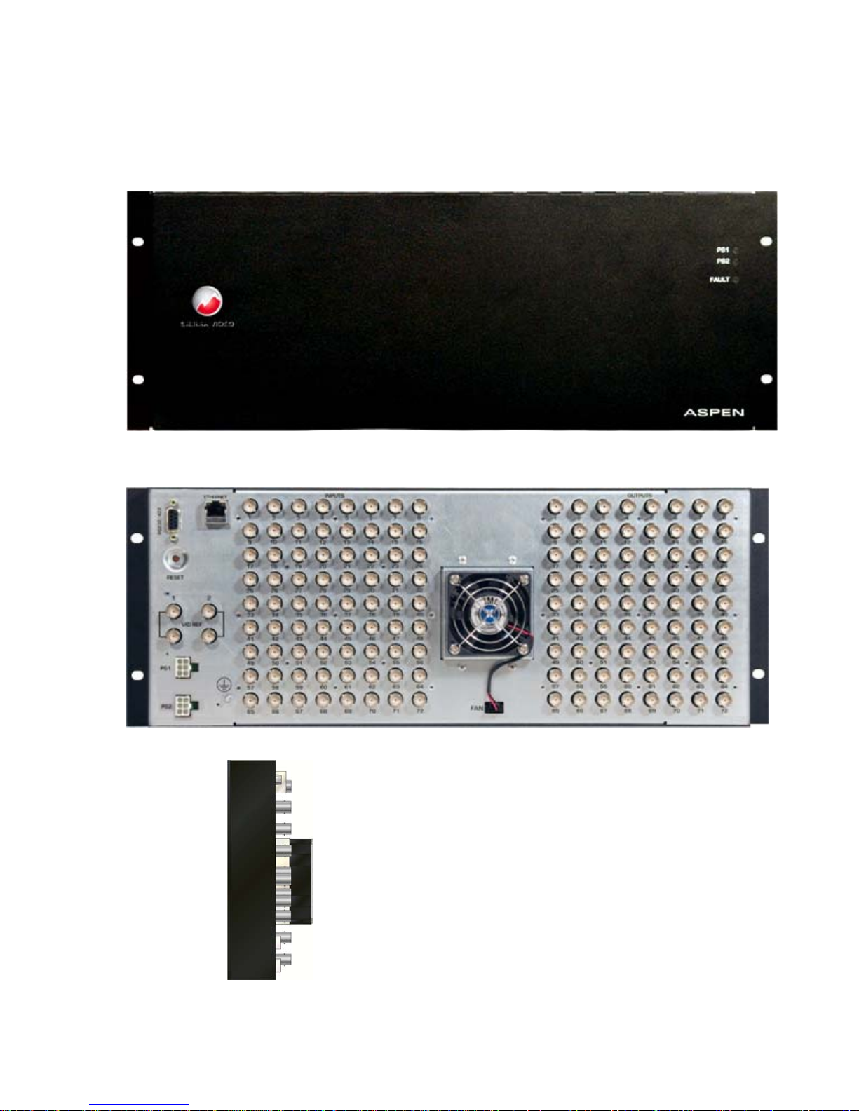
Model 7272 HD-3G
Frame Front Panel
Frame Back Panel
Side
2

SIERRA VIDEO
Installation
Introduction
Installation procedures are similar for all frames covered under this manual. Exceptions, if
any, have been noted in each of the following paragraphs.
Rack Mounting
Carefully inspect the frame to ensure that there has been no shipping damage. Make
sure all shipping material is removed from the routing switcher frame.
Chapter
2
The routing switcher described in this manual can be rack mounted in a standard 19"
(RU) EIA rack assembly and includes rack "ears" at the ends of the front of the frames. It
does not require spacing above or below the unit for ventilation.
To rack mount any of the routing switchers, simply place the unit's rack ears against the
rack rails of the rack, and insert proper rack screws through each of the holes in the rack
ears. Always rack mount the routing switcher prior to plugging the unit into a power
receptacle or attaching any cables.
CAUTION!
The operating temperature range of this product is 0 to 40ºC. Do not exceed the maximum (40ºC)
or minimum (0ºC) operating temperature.
If installed in a closed or multi-rack assembly, the operating ambient temperature of the rack
environment may be greater than the room ambient temperature. Therefore, consideratio n should
be given to installing the equipment in an environment compatible with the manufacturer’s
maximum rated ambient temperature.
Installation of the equipment in a rack should be such that the amount of air flow to the sides of
the routing switcher required for safe operation of the equipment is not compromised.
Dimensions
Aspen 7272 Series HD-3G Routing switcher frame is 4 rack units high, 19” wide, and 2.5” deep.
3
SIERRA VIDEO
r
(Op
Connecting To Video Devices
Video sources and output devices (such as monitors, or recorders) may be connected to
the routing switchers through the BNC type connectors located on the back of the unit.
Keep in mind that the output signal format will be that of the input signal format.
To ensure the highest quality of video routing and switching, special attention should be
observed to cables and connectors.
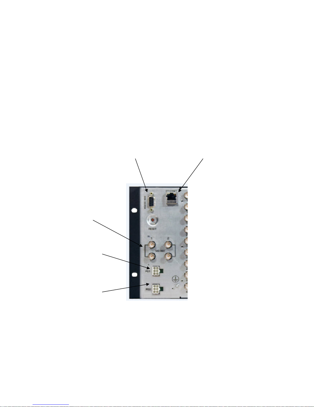
Connecting Peripherals
Control panels, video reference inputs, and power are all connected to the rear of the
frame. The peripherals area may vary depending on the model size and type.
RS-232/422
Control connector
Looping Video
Referencing
Inputs
Primary Power
Connection
Redundant Power
Connection
tional)
10/100 Base T
Ethernet Connecto
4

Reference Connector
There are 4 BNC connectors labeled "VID REF1" and “VID REF 2”. These are "looping"
inputs for SMPTE analog video referencing. Connect composite, or tri-level sync to either
BNC. If desired, use the second BNC to loop the signal to another device. If the loop is
not used, terminate the second BNC with 75 ohms.
If a video reference signal is connected and the router is configured to use redundant
references, the routing switcher, will cause all switching to occur during the vertical
interval of the reference per SMPTE RP-168 and the supported video format standards
shown on page 19. If no reference signal is available or the router is configured for “no
references”, the routing switcher will switch at a random point rather than during the
vertical interval of the reference signal.
AC Power Connections
Aspen routing switchers offer optional redundant power supplies. The redundant power
supply must be ordered seperately. The power supplies have universal AC inputs
100VAC- 240VAC. Voltage selection is not necessary because the power supply senses
the correct AC input automatically.
ASPEN HD/SDI 3G ROUTING SWITCHER
The primary and optional redundant power supplies are external AC to DC converters.
Connect an external 16 AWG or larger wire from earth ground to the chassis of the
system as designated by the earth ground symbol.
CAUTION!
Only an authorized Sierra Video technician can service the switchers. Any user who
makes changes or modifications to the unit without the expressed approval of the
manufacturer will void the warranty
Use the proper AC voltage to supply power to the switcher.
Use only the factory provided AC-DC desktop power supply to supply power to the
switcher.
Use only the recommended interconnect cables to connect the switcher to other frames.
5

SIERRA VIDEO
Configuration
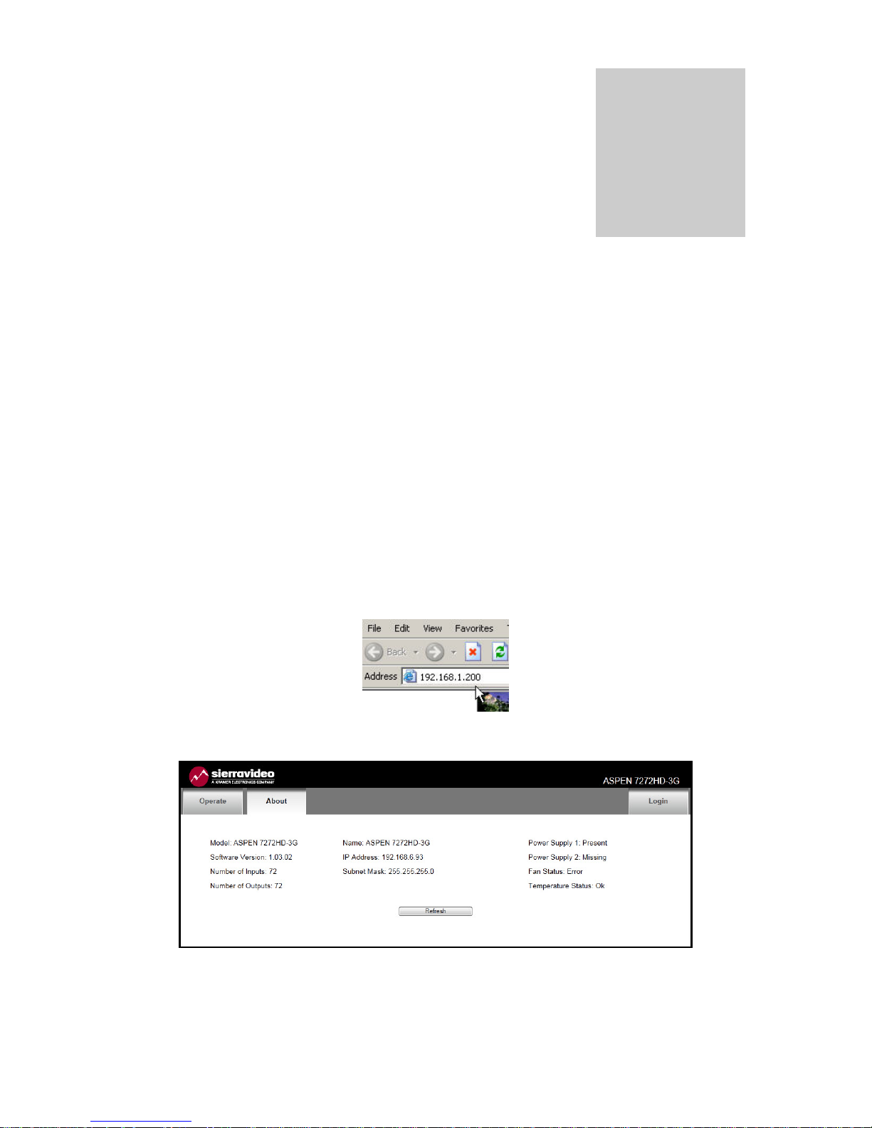
Ethernet Setup
Default IP settings;
IP Address- 192.168.1.200
Subnet mask- 255.255.255.0
Gateway IP Address- 0.0.0.0
Chapter
3
To configure the IP port, the routing switcher must first be connected to your PC. This
can be done by connecting cable to your PC and the routing switcher directly, or the
routing switcher may be added to your existing network. The routing switcher defaults to
an IP address of 192.168.1.200 which will not conflict with other devices in most systems.
If there is an IP address conflict, direct connection must be used to configure the routing
switchers Ethernet port. Once your PC and the routing switcher are on the same Ethernet
network, open your internet browser and type in the default address of the routing
switcher in the address line of the internet browser.
This will open a web page generated by the routing switcher. Routing switcher
information is displayed on this page.
7
SIERRA VIDEO
Note:
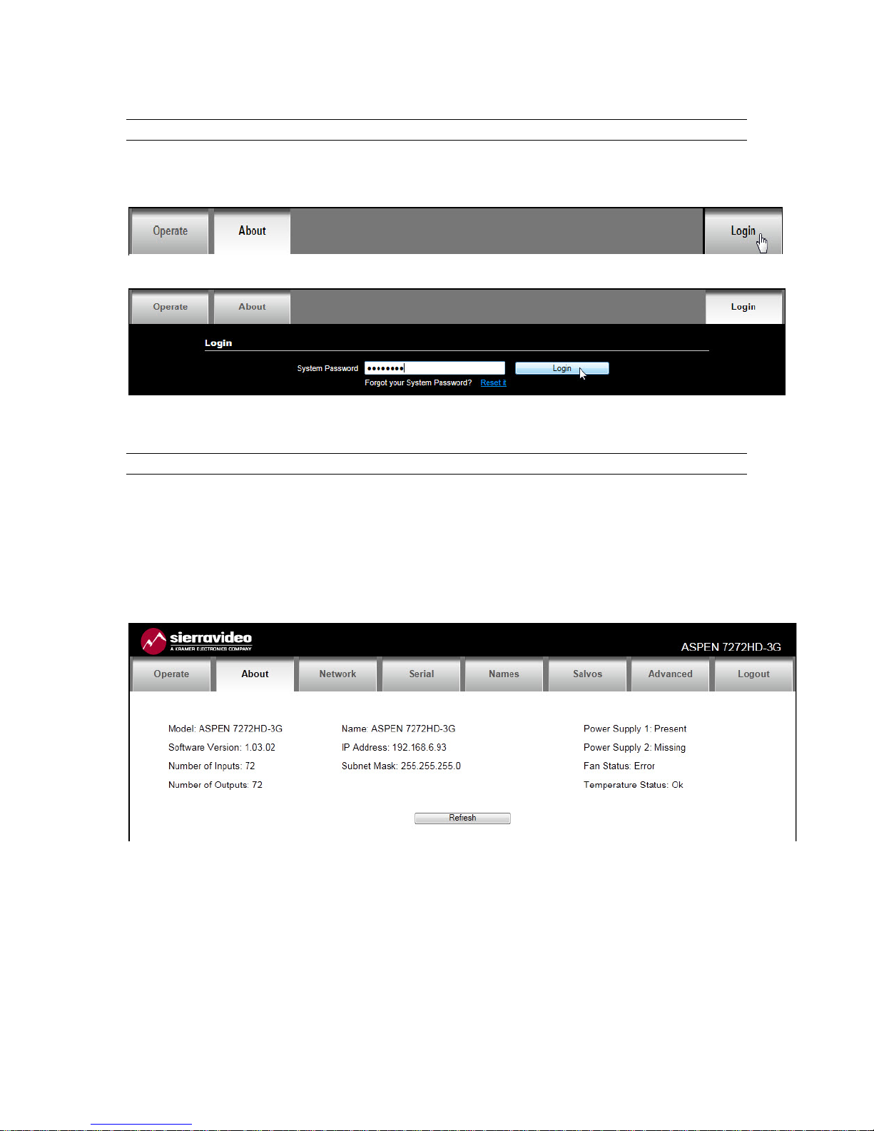
The “Operate” tab is discussed in Chapter 4 “Operation”.
You must login to set or modify Routing switcher parameters. To login, select the login button.
Enter the password and select “Login”.
Note:
The factory default password is “password”. To change the password see the section “Changing
Password” at the end of this chapter.
After a successful login, you will be provided with additional tabs as shown below.
The “refresh” button will re-read the current settings in the routing switcher.
8
 Loading...