

Page 1
Sierra Video Systems Digilinx Audio Analog to Digital Converter
The Sierra Video Systems 507140 contains 2 identical stereo 24 bit Analog to Digital Converters. Each
converter has full differential inputs and both AES and SPIF outputs are available. The converters can be
locked to an external AES audio stream or used free running using an extremely stable internal oscillator
with selectable sample rates of 32Khz, 44.1Khz, and 48Khz.
Input and Output Connections:
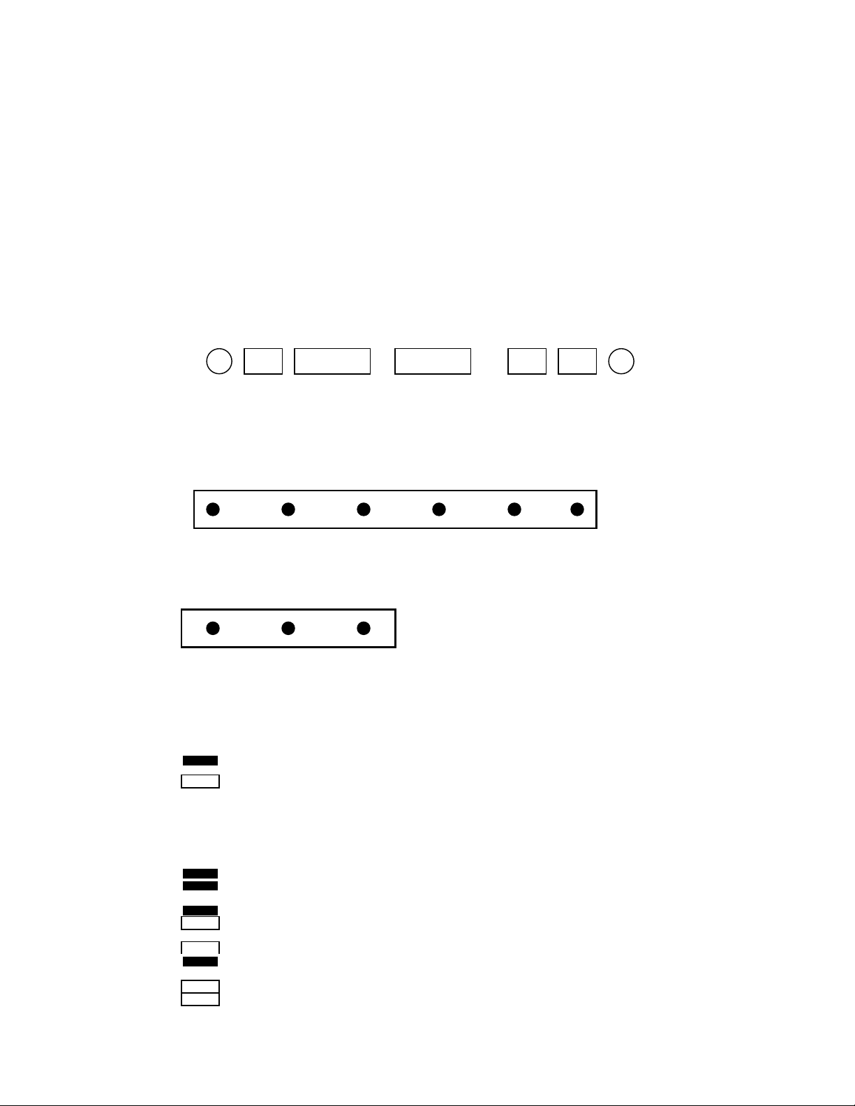
Looking at the back panel of the module, here are the electrical connectors for the card;
A Channel A Channel B Channel External B Channel
Output Output Inputs Inputs Ref Output Output
SPIF AES AES SPIF
For each input connector, the pin outs are;
Left Channel Right Channel
- +
Jumper Settings:
For each output terminal connector, and the external reference input, the pin outs are;
+
• Jumper Definitions:
The Following Graphics are used to describe the jumper setting on the board.
Indicates that a Suite Case Jumper is installed on the indicated header
Indicates that there is NO jumper installed on the indicated header
•
Sample Rate Adjustment
JP13 is used to change the internal Sample Rate Clock for this board. Both Channel A and
Channel B use the same sample rate clock.
48 KHz sample rate
32 KHZ sample rate
44.1 KHz sample rate
INVALID setting - do not use
Gnd Gnd
Gnd
-
:
- +
Page 2
• Output Impedance Adjustment:
The Output impedance can be adjusted separately for the A Channel and the B Channel.
JP4, JP5, and JP6 control the A Channel while JP7, JP8 and JP9 co ntrol the B Channel. Either
output can be set to either a 110 ohm output @ 5 volts peak to peak or 75 ohms @ 1 volt peak to
peak. The output signal is simultaneously available on both the BNC and terminal strip
connectors, however when operating with a 110 ohm output impedance the signal on the BNC is
1/2 amplitude as compared with the terminal strip.
JP4, JP5, and JP6 form the same pattern as JP7, JP8, and J9 on the board and the suite case
jumpers are set in the same pattern for each set of these connectors.
110 ohm Output 75 ohm Output
JP6 (or JP9) JP6 (or JP9)
JP4 (or JP7) JP4 (or JP7)
JP5 (or JP8) JP5 (or JP8)
Page 3

Input Gain Adjustment:
JP3 controls the gain of the input stage for both the A Channel and the B Channel of the Board.
The gain is adjustable in 5 dB steps with a range from a maximum input signal level of +29 dBu to
a maximum input signal level of -1 dBu. 0 dBFs refers to the maximum digital signal level that
can be transmitted out of the Analog to Digital converter. These levels refer to the maximum
signal level. In order to avoid distortion it is recommended that the operating level used be
significantly lower to allow headroom for peak signals to be passed without overload ing the
converter. In a typical application, the normal operating level should be set to be between 16 DB
and 24 DB below the maximum input signal level (depending on the type of audio input being
converted).
Not recommended - Amplifiers will clip Before 0 dBFs is reached
+29 dBu Max Input => 0 dBFs Output
+24 dBu Max Input => 0 dBFs Output
+19 dBu Max Input => 0 dBFs Output
+14 dBu Max Input => 0 dBFS Output
+9 dBu Max Input => 0 dBFs Output
+4 dBu Max Input => 0 dBFs Output
-1 dBu Max Input => 0 dBFs Output
Page 4

• External Reference:
The converter can be set to a sample rate based on an external digital audio reference signal. The
external reference must be a valid digital audio signal. An internal AES receiver will lock to the
reference input signal and if present the sample rates of both channels of the converters can be
switched to the clock derived from this input reference. One position on JP1 is use select the used
of the external reference signal. Only the jumper closest to the JP1 silk screen markings is used.
If a suite case jumper is installed the external reference is used as the conversion clock. If no
jumper is installed the internal clock generator is used for the conversion clock.
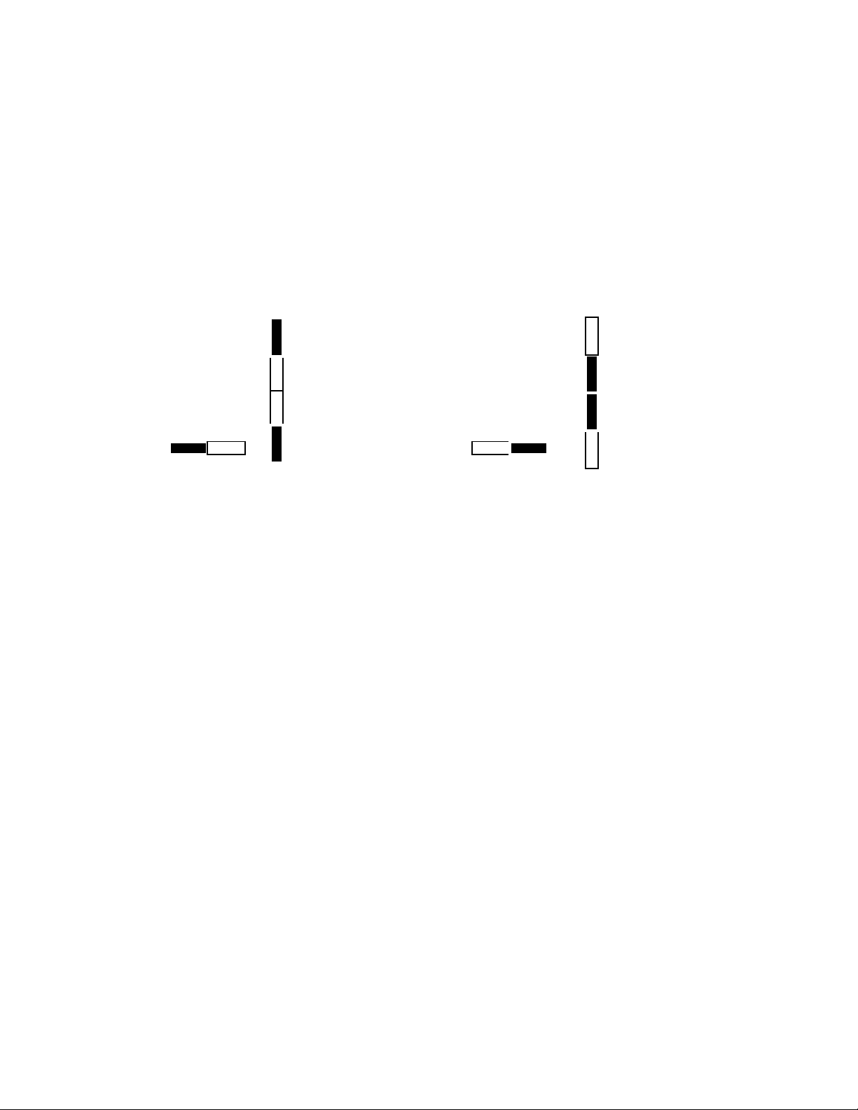
The external reference can be set to be either 110 ohms input impedance or 75 ohm input
impedance using JP2 and JP3 as indicated below;
110 ohm Impedance 75 ohm Impedance
• Unused Jumpers:
At the present time, Jumpers JP11 and JP12 are un-used by the circuitry and are reserved for use
by possible future enhancements of the board.
• Factory default settings:
When the Analog to Digital converter is shipped from the factory, there board is set to use the
internal clock for the conversion running at a 48Khz sampling rate, 110 ohms output impedance in
differential mode (AES), and the maximum input signal is set to +24 dBu.
Page 5

Specifications:
Input
4 analog audio inputs configured as 2 stereo pair
Impedance: > 20Kohm
Common Mode Regection Better than -60 dB
Maximum Input Level Adjustable in 5 dB step from -1 dBu to +29 dBu
Outputs
AES output 110 ohm balanced
SPIF output 75 ohm unbalanced
Jitter < +/- 20 nsec
Conversion
128xFs Digital over sampling filter
Sample rates 32Khz, 44.1Khz, 48Khz or locked to an external reference
Signal to noise -95 dB min (typical -105 dB) A-Weighted
THD 0.006% @ maximum input level
0.01% @ -20dB from max input level
Frequency Response 20Hz to 20Khz +-0.2 dB (48Khz sampling rate)
 Loading...