

Page 1

SIERRA VIDEO SYSTEMS
Composite Video to 270Mbps Video Converter
User’s Guide
507109-00
V 1.1
Page 2
Introduction
The Composite Video to 270Mbps Digital Video Converter accepts analog composite video signals
compatible with US NTSC, Japanese NTSC, std. PAL and PAL-M standards. The incoming signal is
digitized and decoded into a component video signal in the digital domain. The resulting digital component
signal is then passed through a user adjustable blanking circuit which allows cropping of noise along the
left, right, and top of the raster. The resulting signal is then converted into a SMPTE 259 compliant serial
stream and buffered to provide two serial digital component video signals via rear panel BNC connectors.
The amplitude of the analog input signal is adjustable over a +/- 20% range using trimDAC’s; allowing
local and remote control of a traditionally analog adjustment. Pedestal offset is automatically corrected to
track gain changes, but can be adjusted by the user to correct for non-standard sources. An internal ‘clean
up’ PLL keeps serial video phase noise low, even with imperfect video sources. SmartLinx functionality
allows all module controls to be accessed remotely via SVS control panels or a Windows 95/98/NT PC.
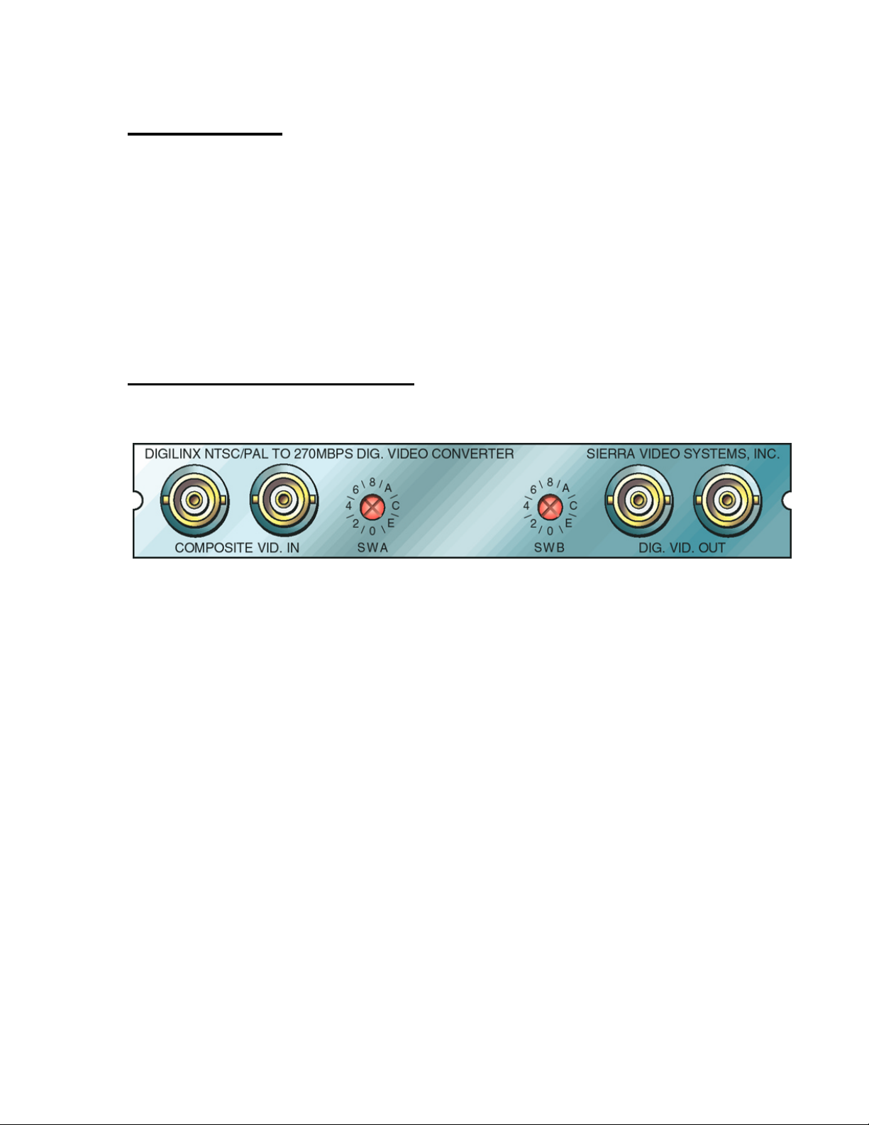
Peripheral Connections
The rear panel provides the following signal connections to the user:
COMPOSITE VID. IN - These two BNC connectors serve as the analog composite video signal
inputs to the product. Two are provided to allow the user to ‘loop through’ the source. The
unused input must be terminated in 75 Ohms. Signals applied here are fed to the digitizer and to
the clock generation circuitry for the module.
DIG. VID. OUT - These two BNC connectors provide serial digital component video signal outputs
from the product. They are copies of one another and either may be used without affecting the
other.
Composite to 270Mbps Video Converter User’s Guide 2
Page 3

Rear Panel Control
The settings stored in the module can be entered and recalled via the two switches on the rear of the
module. This section describes the use of these switches. Note that a ‘nibble’ is a number from 0 to 15.
SWA - Switch A is used to select the parameter to be adjusted by switch B. These are the parameters and
their corresponding switch positions:
Table 1: SWA Positions and Their Functions
Sw. Function
Pos. Selected
0 Set 4 LSB’s of vertical blanking (0 for least blanking)
1 Set 4 MSB’s of vertical blanking (0 for least blanking)
2 Set 4 LSB’s of left edge blanking adjustment (in 74nsec. steps)
3 Set 4 MSB’s of left edge blanking adjustment (in 1.2usec. steps)
4 Set 4 LSB’s of right edge blanking adjustment (in 74nsec. steps)
5 Set 4 MSB’s of right edge blanking adjustment (in 1.2usec. steps)
6 Unused
7 Select ‘no source’ default video standard (0=U.S. NTSC, 1=Jap. NTSC, 2=std. PAL,
3=PAL-M)
8 Set 4 LSB’s of video ADC gain
9 Set 4 MSB’s of video ADC gain
A Set 4 LSB’s of setup
B Set 4 MSB’s of setup
C-D Unused.
E Set EEPROM reg. in which to save parameters.
F Recall parameters from EEPROM register.
SWB - Switch B expresses the numeric value of the parameter pointed to by Switch A. If Switch A enters
and leaves any mode without Switch B being changed, the parameter value stored in RAM for that mode
will not be influenced by the switch value. If Switch B is changed, the parameter pointed at by Switch A
will take on the value of Switch B until Switch A is changed to another setting. Here is an example of how
to set the video DAC gain to zero when Switch B is initially set to ‘0’:
1) set switch A to position 9,
2) change switch B to any value other than zero,
3) set switch B to zero,
4) set switch A to position 8,
5) change switch B to any value other than zero,
6) set switch B to zero.
In other words, to tell the module you want to change a value you must change switch B.
During numeric nibble entries, Switch B’s value expresses a hexadecimal number. This means switch
position A indicates a value of 10, position B, a value of 11, position C, a value of 12, position D, a value of
Composite to 270Mbps Video Converter User’s Guide 3
Page 4

13, position E, a value of 14, and position F indicates a value of 15. Note that some values are not available
for some switches because some values don’t have 256 possible choices. When the limit for such a switch
is reached, the parameter being adjusted will simply stop changing as the switch is moved to larger settings.
Parameter Storage
The present operating values can be stored to EEPROM for the present video standard by setting SWA to
position E and changing SWB to position 1. Note that SWB must CHANGE; even if that means moving it
away from the desired position and back again. The storage to EEPROM occurs when SWA is then moved
OUT of position E. If SWB is set to any value except 1, moving SWA out of position E will NOT result in
parameter storage to EEPROM. Note that separate storage locations exist for all 4 video standards.
Parameter Recall
The present operating values can be recalled from EEPROM for the present video standard by setting SWA
to position F and setting SWB to position 0 or 1. Position 0 recalls factory calibrated settings which cannot
be altered by the user. As SWB is changed, the modules behavior will reflect the parameters previously
stored in the corresponding EEPROM register. Setting SWB to any value except 0-1 will result the recall
of the customer settings for the present standard. The module can automatically load any parameter set upon
power application if SWA is moved OUT of position F after the desired parameter set has be selected with
SWB.
Blanking Adjustments
Vertical and horizontal blanking can be adjusted to remove production or source information which is not
desirable in the outgoing video signal. While vertical blanking is variable in NTSC, horizontal blanking
provided by the incoming digital video signal is always fixed. It is important to remember that this products
vertical blanking line selector extends into areas commonly blanked by the incoming digital video signal,
but that this product will never UN-blank lines of video explicitly blanked by the blanking bits embedded in
the standard video signal.
Vertical blanking adjustments are performed in a spatially contiguous fashion. This means that, as the
blanking control is incremented, lines of video from both fields are unblanked to provide the appearance of
a contiguous, progressive change in the vertical blanking boundary. Note that no blanking adjustment is
provided at the bottom of the active picture.
Horizontal blanking, by definition of the video standards, always eliminates active pixels in the source
material (unless it is set to zero). Because it changes data within the active portion of the video line, these
transitions take place over a number of pixels. If these transitions occurred over a single pixel, the analog
reconstruction filters would ‘ring’, producing ghosting and even sync disruption at each blanking transition.
Values of ‘0’ indicate that the video edge in question is not being modified by the module in any way. All
other values progressively increase the blanking area in 74 nsec. increments using 5 pixel (370 nsec.) long
transitions
Setup Adjustment
The black level, or setup, of the component signal can be varied from its nominal level in 1LSB steps over a
256 LSB range. The factory values for these numbers reflect the nominal setup value for the selected
standard (7.5 IRE units for NTSC, 0 IRE units for Japanese NTSC or PAL).
Composite to 270Mbps Video Converter User’s Guide 4
Page 5

Video ADC Gain
Unlike other products performing digital processing and using video DAC’s, this module does not scale the
composite video signal with digital multipliers. The overall gain is changed by adjusting analog parameters,
providing the user with as much dynamic range at –20% gain as at +20% gain. No analog input offset
adjustment is provided because the module calculates static offset corrections as the gain is changed.
Video Mode Selection
The video mode selection is used to set standard specific values (including gains and blanking values)
without having to provide video input. If the user has made a default standard selection of std. PAL and a
525 line signal arrives, the module will automatically change to US NTSC mode during the 525 line
signal’s presence. If a 525 line standard is selected as default and a 625 line signal is applied to the input,
the module will automatically change to std. PAL mode during the 625 line signal’s presence.
Specifications
Video Input Standard US NTSC, Japanese NTSC, PAL-M, PAL-N
Video Input Connector BNC female X 2 looping unterminated
Video Input Return Loss >35dB @ 10MHz(75 Ohm referenced)
Video Input Range 1Vp-p +/- 20%
Video Output Standard ` SMPTE 259
Video Output Connector BNC female
Video ADC Quantization 10 bits
Video Input Flatness +/- 0.2 dB from 100 KHz to 5 MHz
Video Output Serial Jitter <350 psec p-p with 10 Hz high pass filter.
Time Delay approx. 2H + 1.85usec.
Power Consumption 5V, <1A
8V, <0.5A
-8V, <0.1A
Operating Temperature Range 0 to 50 C, non-condensing
Operating Humidity Range 0 to 95% RH
Composite to 270Mbps Video Converter User’s Guide 5
 Loading...