

Page 1

AirLink LX40
Hardware User Guide
41112510
Rev 1
Page 2

AirLink LX40 Series Hardware User Guide
Important
Notice
Safety and
Hazards
Due to the nature of wireless communications, transmission and reception of data
can never be guaranteed. Data may be delayed, corrupted (i.e., have errors) or be
totally lost. Although significant delays or losses of data are rare when wireless
devices such as the Sierra Wireless modem are used in a normal manner with a
well-constructed network, the Sierra Wireless modem should not be used in
situations where failure to transmit or receive data could result in damage of any
kind to the user or any other party, including but not limited to personal injury,
death, or loss of property. Sierra Wireless accepts no responsibility for damages
of any kind resulting from delays or errors in data transmitted or received using
the Sierra Wireless modem, or for failure of the Sierra Wireless modem to
transmit or receive such data.
Do not operate the Sierra Wireless modem in areas where blasting is in progress,
near medical equipment, near life support equipment, or any equipment which
may be susceptible to any form of radio interference. In such areas, the Sierra
Wireless modem MUST BE POWERED OFF. The Sierra Wireless modem can
transmit signals that could interfere with this equipment.
The driver or operator of any vehicle should not operate the Sierra Wireless
modem while in control of a vehicle. Doing so will detract from the driver or
operator's control and operation of that vehicle. In some states and provinces,
operating such communications devices while in control of a vehicle is an offence.
Warning: EXPLOSION HAZARD–DO NOT DISCONNECT WHILE CIRCUIT IS LIVE
UNLESS THE AREA IS KNOWN TO BE NON-HAZARDOUS.
Limitation of
Liability
Avertrissement: RISQUE D’EXPLOSION-NE PAS DEBRANCHER TANT QUE LE
CIRCUIT EST SOURS TENSION, A MOINES QU’IL NE S’AGISSE D’UN
EMPLACEMENT NON DANGEREUX.
Warning: DO NOT USE THE USB CONNECTOR IN A HAZARDOUS AREA.
Avertrissement: NE PAS UTILISER DE CONNECTEUR USB DANS LES
ENVIRONNEMENTS DANGEREUX.
Warning: DO NOT USE THE RESET BUTTON IN A HAZARDOUS AREA.
Avertrissement: NE PAS UTILISER LE BOUTON DE RESET DANS UN
ENVIRONNEMENT DANGEREUX.
The information in this manual is subject to change without notice and does not
represent a commitment on the part of Sierra Wireless. SIERRA WIRELESS AND
ITS AFFILIATES SPECIFICALLY DISCLAIM LIABILITY FOR ANY AND ALL
DIRECT, INDIRECT, SPECIAL, GENERAL, INCIDENTAL, CONSEQUENTIAL,
PUNITIVE OR EXEMPLARY DAMAGES INCLUDING, BUT NOT LIMITED TO,
LOSS OF PROFITS OR REVENUE OR ANTICIPATED PROFITS OR REVENUE
Rev 1 November 2018 2 41112510
Page 3
Preface
ARISING OUT OF THE USE OR INABILITY TO USE ANY SIERRA WIRELESS
PRODUCT, EVEN IF SIERRA WIRELESS AND/OR ITS AFFILIATES HAS BEEN
ADVISED OF THE POSSIBILITY OF SUCH DAMAGES OR THEY ARE
FORESEEABLE OR FOR CLAIMS BY ANY THIRD PARTY.
Notwithstanding the foregoing, in no event shall Sierra Wireless and/or its affiliates
aggregate liability arising under or in connection with the Sierra Wireless product,
regardless of the number of events, occurrences, or claims giving rise to liability,
be in excess of the price paid by the purchaser for the Sierra Wireless product.
Patents This product may contain technology developed by or for Sierra Wireless Inc. This
product includes technology licensed from QUALCOMM
manufactured or sold by Sierra Wireless Inc. or its affiliates under one or more
patents licensed from MMP Portfolio Licensing.
®
. This product is
Copyright © 2018 Sierra Wireless. All rights reserved.
Trademarks Sierra Wireless
are registered trademarks of Sierra Wireless.
Windows
Corporation.
Macintosh
the U.S. and other countries.
QUALCOMM
under license.
Other trademarks are the property of their respective owners.
®
, AirPrime®, AirLink®, AirVantage® and the Sierra Wireless logo
®
and Windows Vista® are registered trademarks of Microsoft
®
and Mac OS X® are registered trademarks of Apple Inc., registered in
®
is a registered trademark of QUALCOMM Incorporated. Used
Contact
Information
Sales information and technical
support, including warranty and returns
Web: sierrawireless.com/company/contact-us/
Global toll-free number: 1-877-687-7795
6:00 am to 5:00 pm PST
Corporate and product information Web: sierrawireless.com
Rev 1 November 2018 3 41112510
Page 4

Contents
Introduction to the LX40 . . . . . . . . . . . . . . . . . . . . . . . . . . . . . . . . . . . . . . . . . . . . . . . . . . .7
Key Features . . . . . . . . . . . . . . . . . . . . . . . . . . . . . . . . . . . . . . . . . . . . . . . . . . . . . . . . . 7
Description . . . . . . . . . . . . . . . . . . . . . . . . . . . . . . . . . . . . . . . . . . . . . . . . . . . . . . . . . . . 8
Sample Power Consumption Scenarios . . . . . . . . . . . . . . . . . . . . . . . . . . . . . . . . . . . . . 9
Accessories . . . . . . . . . . . . . . . . . . . . . . . . . . . . . . . . . . . . . . . . . . . . . . . . . . . . . . . . . . 9
Warranty. . . . . . . . . . . . . . . . . . . . . . . . . . . . . . . . . . . . . . . . . . . . . . . . . . . . . . . . . . . . . 9
Installation and Startup . . . . . . . . . . . . . . . . . . . . . . . . . . . . . . . . . . . . . . . . . . . . . . . . . .10
Tools and Materials Required. . . . . . . . . . . . . . . . . . . . . . . . . . . . . . . . . . . . . . . . . . . . 10
Installation Overview . . . . . . . . . . . . . . . . . . . . . . . . . . . . . . . . . . . . . . . . . . . . . . . . . . 10
Step 1—Insert the SIM Card . . . . . . . . . . . . . . . . . . . . . . . . . . . . . . . . . . . . . . . . . . . . 11
Step 2—Mount and Ground the LX40 Chassis . . . . . . . . . . . . . . . . . . . . . . . . . . . . . . 11
Grounding the LX40 . . . . . . . . . . . . . . . . . . . . . . . . . . . . . . . . . . . . . . . . . . . . . . . . .12
Flat Mount . . . . . . . . . . . . . . . . . . . . . . . . . . . . . . . . . . . . . . . . . . . . . . . . . . . . . . . .13
Mounting in a High Vibration Environment . . . . . . . . . . . . . . . . . . . . . . . . . . . . . . . .14
DIN Rail Mount . . . . . . . . . . . . . . . . . . . . . . . . . . . . . . . . . . . . . . . . . . . . . . . . . . . . .15
Step 3—Connect the Antennas . . . . . . . . . . . . . . . . . . . . . . . . . . . . . . . . . . . . . . . . . . 16
Recommended Antenna Separation . . . . . . . . . . . . . . . . . . . . . . . . . . . . . . . . . . . .17
Step 4—Connect the Data Cables. . . . . . . . . . . . . . . . . . . . . . . . . . . . . . . . . . . . . . . . 17
Step 5—Connect the Power . . . . . . . . . . . . . . . . . . . . . . . . . . . . . . . . . . . . . . . . . . . . 17
Cable Strain Relief . . . . . . . . . . . . . . . . . . . . . . . . . . . . . . . . . . . . . . . . . . . . . . . . . .18
Fusing . . . . . . . . . . . . . . . . . . . . . . . . . . . . . . . . . . . . . . . . . . . . . . . . . . . . . . . . . . .18
Power Connector on the LX40 . . . . . . . . . . . . . . . . . . . . . . . . . . . . . . . . . . . . . . . . .19
Wiring Diagrams . . . . . . . . . . . . . . . . . . . . . . . . . . . . . . . . . . . . . . . . . . . . . . . . . . . .20
Step 6—I /O Configuration . . . . . . . . . . . . . . . . . . . . . . . . . . . . . . . . . . . . . . . . . . . . . . 22
Step 7—Check the Router Operation . . . . . . . . . . . . . . . . . . . . . . . . . . . . . . . . . . . . . 28
LED Behavior . . . . . . . . . . . . . . . . . . . . . . . . . . . . . . . . . . . . . . . . . . . . . . . . . . . . . .29
Ethernet LEDs . . . . . . . . . . . . . . . . . . . . . . . . . . . . . . . . . . . . . . . . . . . . . . . . . . . . .30
Step 8—Configure the Software . . . . . . . . . . . . . . . . .
. . . . . . . . . . . . . . . . . . . . . . . . 31
Reboot the LX40. . . . . . . . . . . . . . . . . . . . . . . . . . . . . . . . . . . . . . . . . . . . . . . . . . . . . . 32
Reset the LX40 to Factory Default Settings . . . . . . . . . . . . . . . . . . . . . . . . . . . . . . . . . 32
Recovery Mode . . . . . . . . . . . . . . . . . . . . . . . . . . . . . . . . . . . . . . . . . . . . . . . . . . . . . . 33
Rev 1 November 2018 4 41112510
Page 5

Contents
Specifications . . . . . . . . . . . . . . . . . . . . . . . . . . . . . . . . . . . . . . . . . . . . . . . . . . . . . . . . . . 34
Certification and Interoperability . . . . . . . . . . . . . . . . . . . . . . . . . . . . . . . . . . . . . . . . . 34
Mobile Network Operator Certification. . . . . . . . . . . . . . . . . . . . . . . . . . . . . . . . . . . . . 34
Network Technology . . . . . . . . . . . . . . . . . . . . . . . . . . . . . . . . . . . . . . . . . . . . . . . . . . 35
Environmental Testing . . . . . . . . . . . . . . . . . . . . . . . . . . . . . . . . . . . . . . . . . . . . . . . . . 35
Host Interfaces. . . . . . . . . . . . . . . . . . . . . . . . . . . . . . . . . . . . . . . . . . . . . . . . . . . . . . . 36
SIM Card Interface. . . . . . . . . . . . . . . . . . . . . . . . . . . . . . . . . . . . . . . . . . . . . . . . . . . . 37
Mechanical Specifications . . . . . . . . . . . . . . . . . . . . . . . . . . . . . . . . . . . . . . . . . . . . . . 37
Screw Torque Settings. . . . . . . . . . . . . . . . . . . . . . . . . . . . . . . . . . . . . . . . . . . . . . . . . 37
Operating Voltage . . . . . . . . . . . . . . . . . . . . . . . . . . . . . . . . . . . . . . . . . . . . . . . . . . . . 37
Power Specifications . . . . . . . . . . . . . . . . . . . . . . . . . . . . . . . . . . . . . . . . . . . . . . . . 37
Protocols . . . . . . . . . . . . . . . . . . . . . . . . . . . . . . . . . . . . . . . . . . . . . . . . . . . . . . . . . . . 38
Wi-Fi Performance . . . . . . . . . . . . . . . . . . . . . . . . . . . . . . . . . . . . . . . . . . . . . . . . . . . . 39
Wi-Fi Channels Supported. . . . . . . . . . . . . . . . . . . . . . . . . . . . . . . . . . . . . . . . . . . . . . 39
Radio Frequency Bands . . . . . . . . . . . . . . . . . . . . . . . . . . . . . . . . . . . . . . . . . . . . . . . 40
Radio Module Conducted Transmit Power . . . . . . . . . . . . . . . . . . . . . . . . . . . . . . . . . 44
Mechanical Specifications . . . . . . . . . . . . . . . . . . . . . . . . . . . . . . . . . . . . . . . . . . . . . . 46
Regulatory Information . . . . . . . . . . . . . . . . . . . . . . . . . . . . . . . . . . . . . . . . . . . . . . . . . . 47
Important Information for North American Users . . . . . . . . . . . . . . . . . . . . . . . . . . . . . 47
RF Exposure . . . . . . . . . . . . . . . . . . . . . . . . . . . . . . . . . . . . . . . . . . . . . . . . . . . . . . 48
Accessories . . . . . . . . . . . . . . . . . . . . . . . . . . . . . . . . . . . . . . . . . . . . . . . . . . . . . . . . . . . 51
DC Power Cable (Black Connector) . . . . . . . . . . . . . . . . . . . . . . . . . . . . . . . . . . . . . . 51
Rev 1 November 2018 5 41112510
Page 6

AirLink LX40 Series Hardware User Guide
AC Power Adapter (Black Connector) . . . . . . . . . . . . . . . . . . . . . . . . . . . . . . . . . . . . . 52
AC Power Adapter Input . . . . . . . . . . . . . . . . . . . . . . . . . . . . . . . . . . . . . . . . . . . . . 52
AC Power Adapter Output . . . . . . . . . . . . . . . . . . . . . . . . . . . . . . . . . . . . . . . . . . . . 52
AC Power Adapter Environmental Specifications . . . . . . . . . . . . . . . . . . . . . . . . . . 53
AC Power Adapter Reliability and Quality Control . . . . . . . . . . . . . . . . . . . . . . . . . . 53
AC Power Adapter Safety Standards . . . . . . . . . . . . . . . . . . . . . . . . . . . . . . . . . . . 53
AC Power Adapter EMC Standards . . . . . . . . . . . . . . . . . . . . . . . . . . . . . . . . . . . . 53
AC Power Adapter Hazardous Substances . . . . . . . . . . . . . . . . . . . . . . . . . . . . . . . 54
AC Power Adapter Energy Efficiency . . . . . . . . . . . . . . . . . . . . . . . . . . . . . . . . . . . 54
Index. . . . . . . . . . . . . . . . . . . . . . . . . . . . . . . . . . . . . . . . . . . . . . . . . . . . . . . . . . . . . . . . . 55
Rev 1 November 2018 6 41112510
Page 7

1: Introduction to the LX40
This hardware user guide is for the Sierra Wireless® AirLink® LX40 LTE Router.
Features and specifications described in this user guide apply to all variants of the
LX40 unless otherwise noted.
The AirLink LX40 is designed for Commercial and Enterprise LTE network
connectivity.
LX40 provides purpose-built, secure, reliable, managed Cellular LTE networking in
building automation, digital signage, taxis, ATMs, kiosks and point-of-sale terminals.
As part of the AirLink Essential series, the LX40 is designed to meet the
environmental and performance requirements of these applications, while delivering
superior reliability and uninterrupted operation in fixed, indoor and protected outdoor
environments.
LX40 is available with optional Wi-Fi and rated for shock and vibration. It offers Dual
Band 802.11ac Wi-Fi.
The LX40 comes in LTE Cat 4 regional variants, and a Global LPWA (Low-Power
Wide Area) variant offering LTE-M/NB-IoT for applications where low data rates,
enhanced cellular coverage and global deployment is required.
Key Features
1
• LTE Cat-4 and Cat-M1/NB1 (LX40 variants)
• 2.4/5 GHz 802.11ac Wi-Fi (Wi-Fi models only)
• Gigabit Ethernet port (LAN/WAN)
• 1 configurable GPIO
• Power over Ethernet (IEEE 802.3af)
• USB 2.0 Micro-B Connector
For information on configuring these features, refer to the ALEOS Software
Configuration User Guide.
Rev 1 November 2018 7 41112510
Page 8
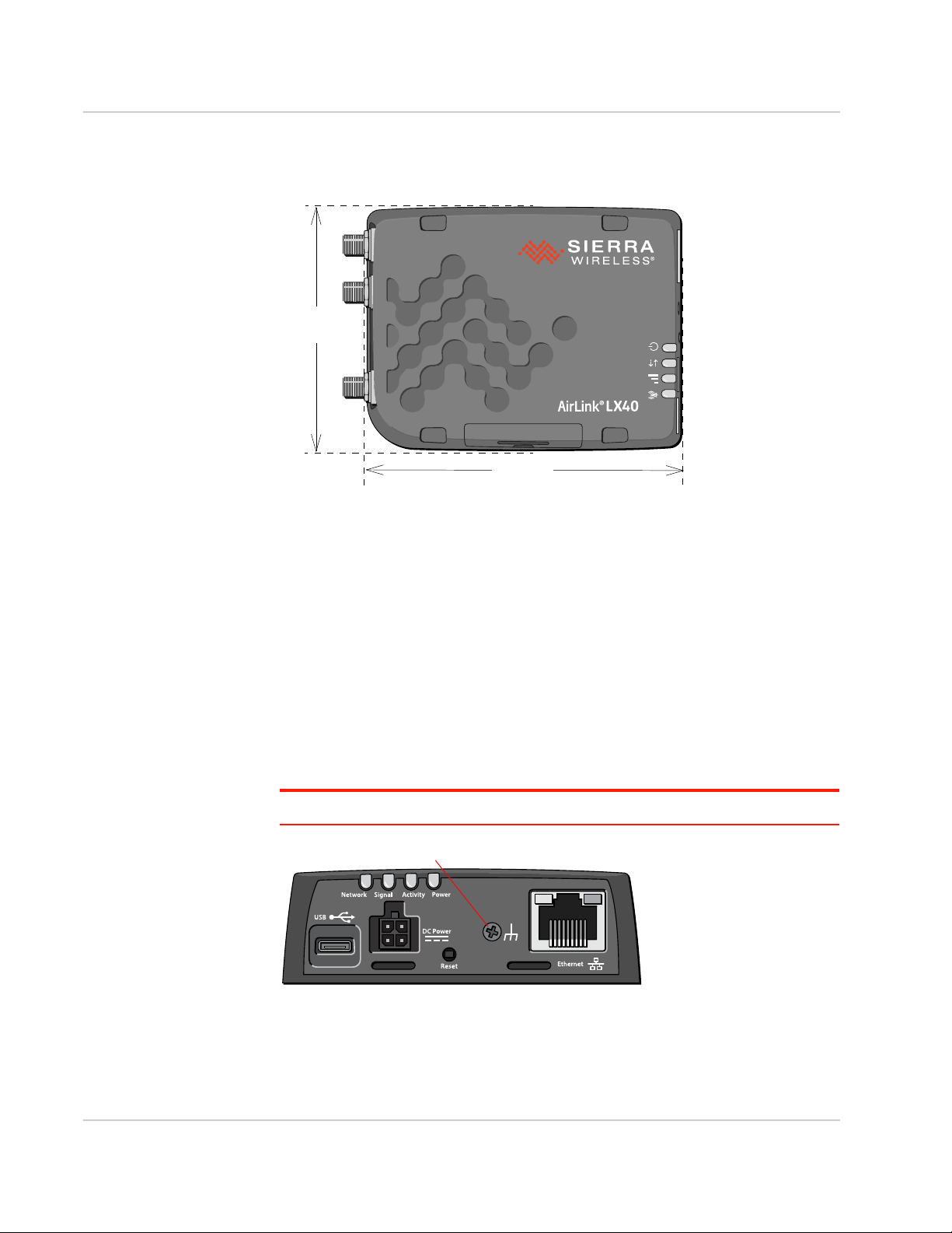
AirLink LX40 Series Hardware User Guide
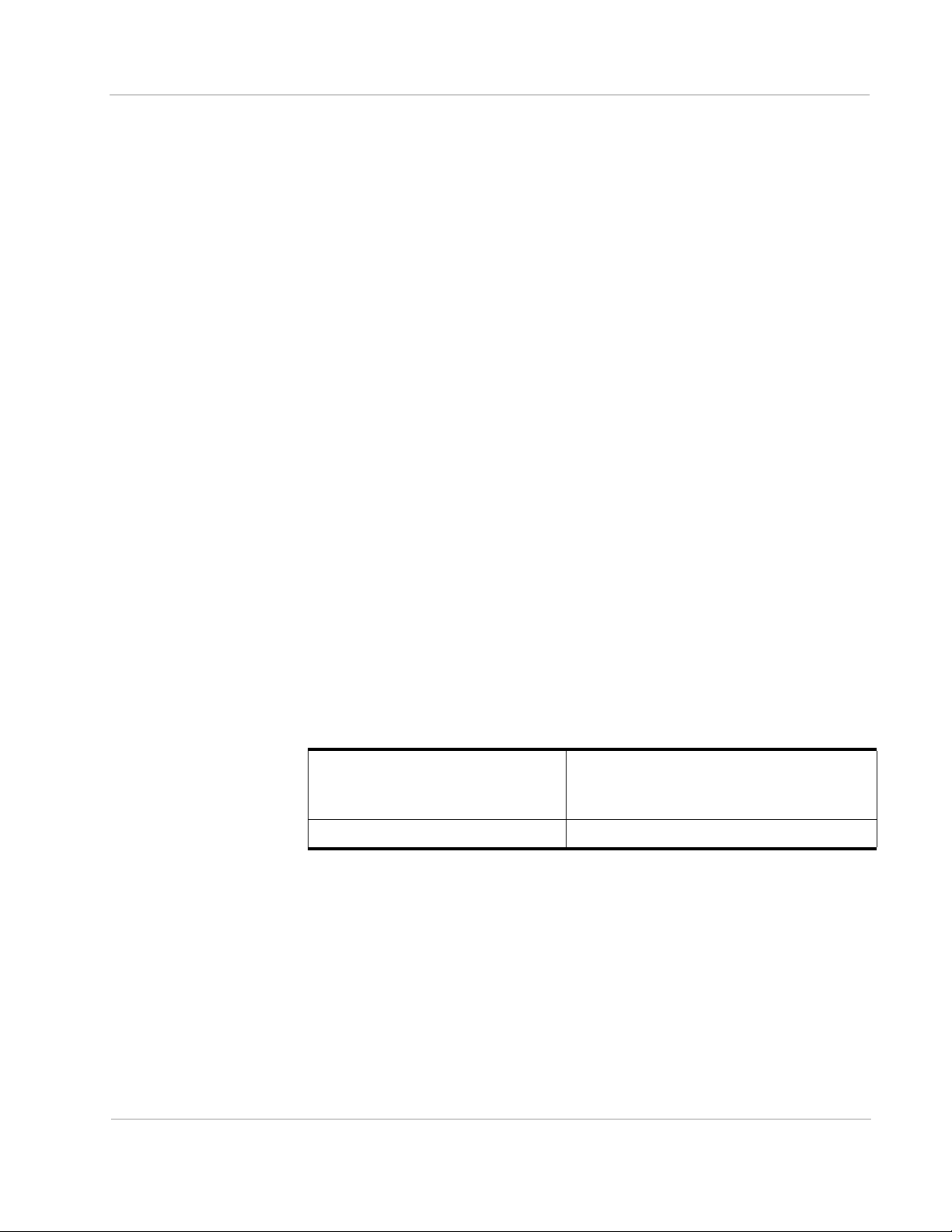
Power Connector
(See page 17.)
Mini-SIM 2FF Card slot
(See Insert the SIM Card
on page 18)
Cellular Antenna Connector
Diversity Antenna Connector
USB 2.0 Micro-AB Port
(See Ethernet on page 36.)
(See USB on page 36.)
Reset button
(See page 32.)
RJ-45 Ethernet Port
LEDs (See LED Behavior on page 29.)
Wi-Fi Antenna Connector*
(See Connect the Antennas on page 16.)
*Wi-Fi model
Grounding screw
(See page 11.)
Description
Figure 1-1: LX40 Connectors, LEDs and SIM Card Holder
Rev 1 November 2018 8 41112510
Page 9
Sample Power Consumption Scenarios
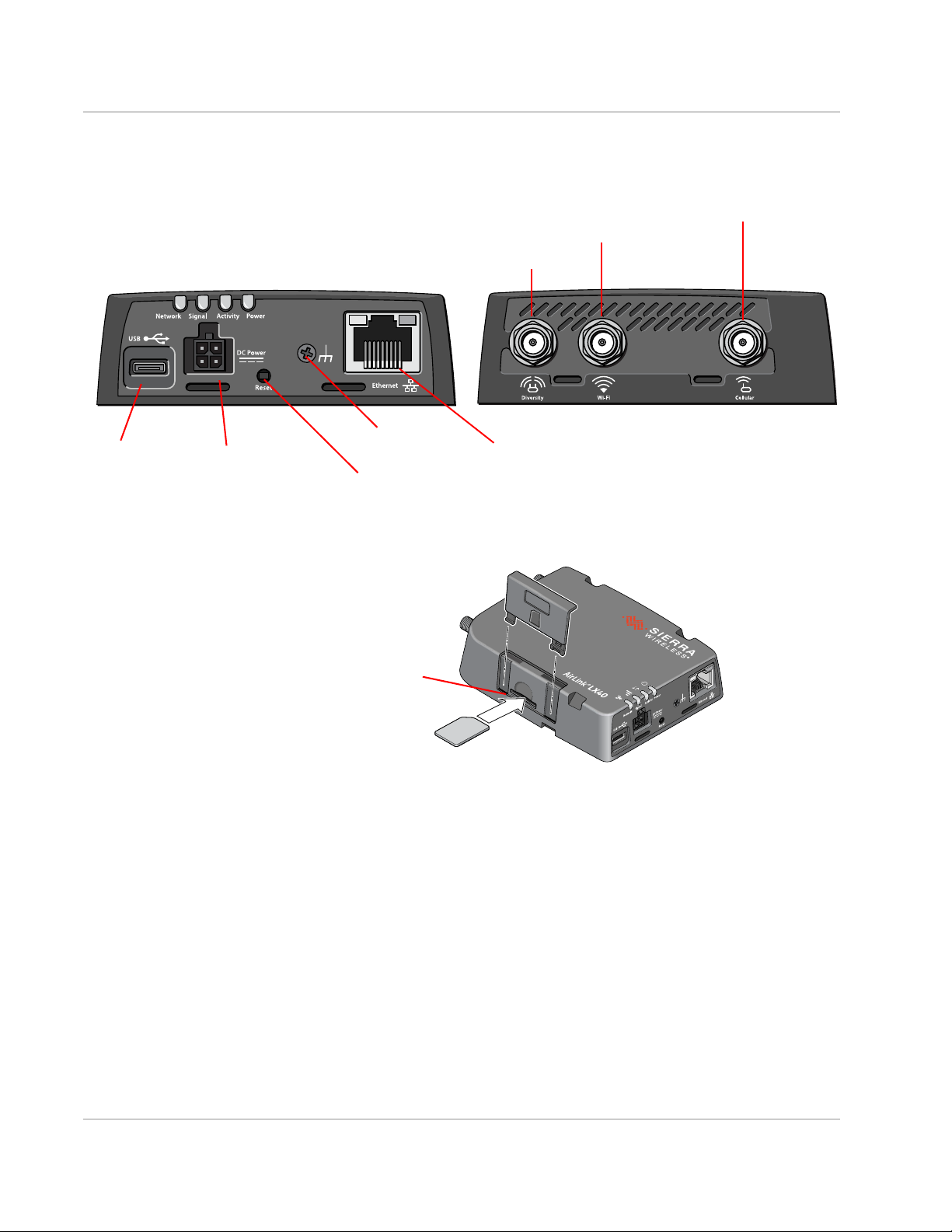
Table 1-1: Power Consumption Scenarios
Introduction to the LX40
Scenario Radio Ethernet USB Wi-Fi
Standby Mode — — — — 20 mW
Ethernet
(10 BaseT)
Ethernet
(100 BaseT)
Ethernet (GigE) Idle Attached 1000 BaseT Full duplex Disabled Disabled 1000 mW
Wi-Fi AP 5GHz Idle Attached Disabled Disabled Enabled
Typical Use
(non-Wi-Fi)
Typical Use
(Wi-Fi)
Maximum Power
(non-Wi-Fi)
Maximum Power
(Wi-Fi)
Idle Attached 10 BaseT Full duplex Disabled Disabled 700 mW
Idle Attached 100 BaseT Full duplex Disabled Disabled 750 mW
(idle)
Attached and
connected (20 dBm)
Attached and
connected (20 dBm)
Attached and
connected (23 dBm)
Attached and
connected (23 dBm)
100 BaseT Full duplex Enabled Idle Disabled 3250 mW
100 BaseT Full duplex Enabled Idle Enabled
Enabled (1000 BaseT full
duplex with Auto negotiation
as speed setting)
Enabled (1000 BaseT full
duplex running with Auto
negotiation as speed
setting)
Enabled
(pinging)
Enabled
(pinging)
(idle)
Disabled 5250 mW
Enabled
(1000
BaseT full
duplex
running)
Powera
(1.7 mA)
(58.3 mA)
(62.5 mA)
(83.3 mA)
110 0 mW
(91.6 mA)
(270.8 mA)
3700 mW
(308.3 mA)
(437.5 mA)
6250 mW
(520.8 mA)
7500 mW
(PoE)
Inrush Current 1 A @ 12 V (Averaged over 100 s)
a. Power consumption was measured at 12 V unless noted.
Accessories
The following items come with the LX40 router:
• DC power cable
• Quick Start Guide
The following items can be ordered separately from Sierra Wireless:
• Universal AC power adapter (part number 2000579)
· Voltage input: 100–240 VAC
· Current output: 1.5 A
Warranty
The LX40 comes with a 3-year warranty, and has an optional 2-year warranty
extension.
Rev 1 November 2018 9 41112510
Page 10

2: Installation and Startup
This chapter shows how to connect, install and start the AirLink LX40. It also
describes the front panel LEDs, and I/O functionality.
Note: Field wiring and connections in hazardous locations must be connected as per the wiring
methods requirement for Class 2 circuits mentioned in the National Electric Code and the
Canadian Electric Code.
Note: The LX40 Series gateway installation must be done by a qualified technician.
Tools and Materials Required
• Power supply—AC or DC (DC power cable is supplied by Sierra Wireless)
· Not required if using Power over Ethernet
• A SIM card (provided by your mobile network operator)
• Small slot-head screwdriver (to remove SIM door)
• Computer with Ethernet cable
• LTE MIMO antennas— Main and Diversity
· Diversity antenna not required for CatM1/NB-IoT
• Wi-Fi antenna (LX40 Wi-Fi model only)
2
Installation Overview
The steps for a typical installation are:
1. Insert the SIM card — page 11.
2. Mount and ground the LX40 chassis— page 11.
3. Connect the antennas— page 16.
4. Connect the data cables— page 17.
5. Connect the power— page 17.
6. Check the router operation— page 28.
7. Configure the software— page 31.
The following sections describe these steps in detail. Read these sections carefully
before performing the installation.
Warning: The default ACEmanager password is printed on the device label. You should
always change the default password after logging in to ACEmanager. However, if the unit must
be reset to factory default settings, your custom password may also be reset to default
(depending on the Reset Mode configured in ACEmanager). Before installation, please record
the default password and store it in a secure place. See also Reset the LX40 to Factory Default
Settings on page 32.
Rev 1 November 2018 10 41112510
Page 11
Installation and Startup
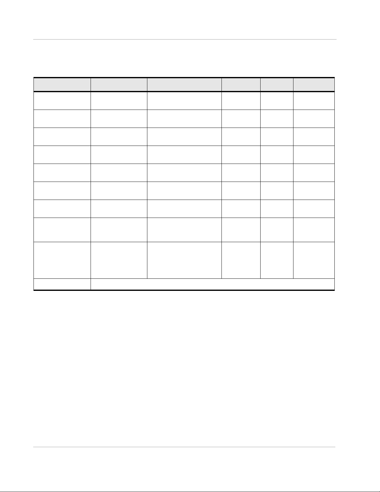
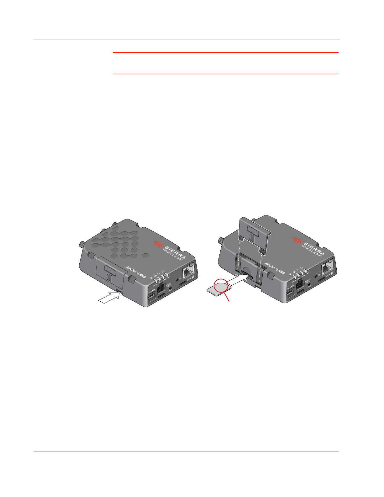
Note the orientation of notched corner
for proper SIM card alignment.
Note: Depending on where you are installing the LX40, you may want to mount the router
before connecting the antenna, cables and power.
Step 1—Insert the SIM Card
If the SIM card has not already been installed, insert the SIM card into the router
before connecting any external equipment or power to the router.
To install the SIM card:
1. Remove the SIM card cover. Press the tab with a screwdriver while sliding the
cover upwards.
2. Orient the SIM card as shown in Figure 2-1 (with the gold contacts facing
down).
3. Gently slide the SIM card into the slot until it clicks into place.
To remove the SIM card, press the SIM card in, and release it. Gently grip the
SIM card and pull it out.
4. Replace the SIM card cover.
Figure 2-1: Installing the SIM Card
Step 2—Mount and Ground the LX40 Chassis
You can mount the LX40 on a flat surface, and secure it using a mounting bracket
(see Flat Mount on page 13). If you are installing the LX40 in a high-vibration
environment, you can further secure the LX40 to the mounting bracket using
nylon cable ties.
Mount the router where:
• There is easy access for attaching the cables
• Cables will not be constricted, close to high amperages or exposed to
extreme temperatures
Rev 1 November 2018 11 41112510
Page 12
AirLink LX40 Series Hardware User Guide
103 mm
4 1/16 in.
79 mm
3 1/8 in.
Grounding point
• The front panel LEDs are easily visible
• There is adequate airflow
• It is away from direct exposure to the elements, such as sun, rain, dust, etc.
Figure 2-2: Mounting and Grounding the LX40
Grounding the LX40
Sierra Wireless strongly recommends that you always ground the chassis using
the grounding point shown in Figure 2-3.
For DC installations (with a fixed “system” ground reference), Sierra Wireless
recommends grounding the LX40 chassis to this system ground reference.
To ensure a good grounding reference, connect one end of a short 18 AWG or
larger gauge wire with a ring terminal connector to the ground terminal on the
LX40 and connect the other end to your main grounding point.
The ground terminal comes with an M2.5 × 6 mm screw. You can use a longer
M2.5 screw if the terminal connector on your ground wire requires one.
Note: Do not overtighten the grounding screw. Tighten to a maximum torque of 0.4 kg/cm.
Figure 2-3: Ground connector
Rev 1 November 2018 12 41112510
Page 13
Installation and Startup
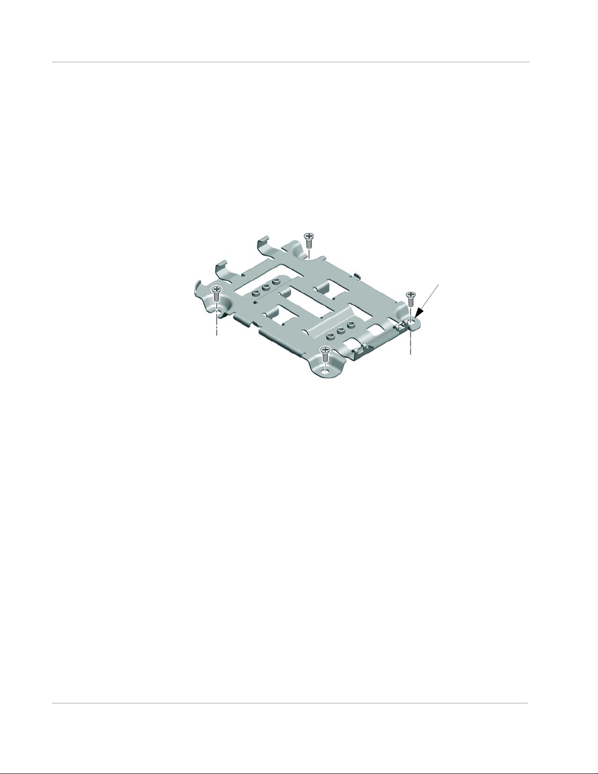
Holes are Ø 4.3 mm (M4 compatible;
use hardware appropriate for your
mounting surface)
Flat Mount
To mount the LX40 permanently to any surface or if you are mounting the LX40
on a DIN rail, order an LX40 mounting bracket kit (P/N 6001221) from Sierra
Wireless. The kit contains:
• Mounting bracket
• DIN rail clip (35 mm EN 50022) (see DIN Rail Mount on page 15)
• Screws for attaching the DIN rail clip to the mounting bracket
To mount the LX40 on a flat surface:
1. Attach the bracket to the mounting surface, using the attachment points
shown in Figure 2-4.
Figure 2-4: Mounting Bracket, showing attachment points
2. Snap the LX40 onto the bracket (see Figure 2-5 on page 14).
a. Angle the LX40 with the antenna connectors downwards, and fit the
bracket clasps against the indentations on the end of the LX40. The
raised edge of the bracket should match the rounded corner of the LX40.
b. Bring the other end of the LX40 down onto the bracket and snap it into
place. The bracket clasps should fit into the indentations on the end of the
LX40.
Rev 1 November 2018 13 41112510
Page 14
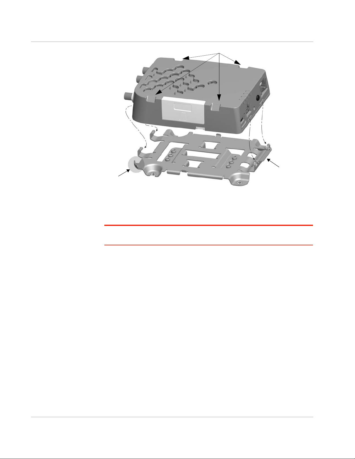
AirLink LX40 Series Hardware User Guide
Raised edge
Notches for cable ties
Step a: Attach
antenna end
Step b: Snap other
end into place.
Press the tab to
disengage the clasps
if removing the LX40.
Figure 2-5: Attaching the LX40 to the bracket
Mounting in a High Vibration Environment
Note: If you are mounting the LX40 in a high vibration area, Sierra Wireless strongly
recommends using two nylon cable ties to secure the LX40 on the bracket.
1. Thread the ties beneath the bracket.
2. Wrap the ties around the LX40, using the notches in the LX40 casing (see
Figure 2-5) to align the ties.
3. Tighten and secure the ties around the LX40 and trim off the excess length of
the ties.
Rev 1 November 2018 14 41112510
Page 15
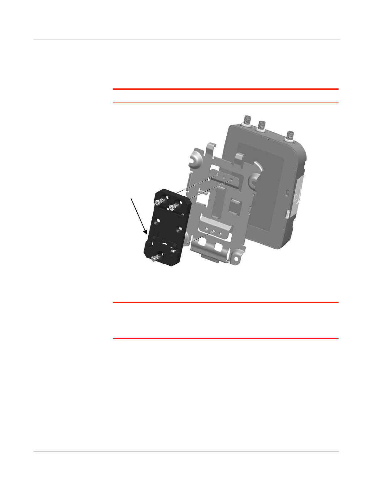
Installation and Startup
Ensure spring clip
is at the bottom
To mount the LX40 with antenna
connectors pointing down, rotate the
DIN clip 180 degrees before attaching.
DIN Rail Mount
You can mount the LX40 on a DIN rail in a vertical orientation, with the antenna
connectors pointing up or down.
Note: The DIN rail mounting clip should only be used on a horizontally-mounted DIN rail.
Rev 1 November 2018 15 41112510
Figure 2-6: Attaching the DIN Rail Mounting Clip
To attach the LX40 to a horizontally mounted DIN rail:
Note: Before installing the LX40 in its final location, you may want to install the SIM card
(see page 11), attach antennas (see page 16), power up the device (see page 17) and test
the network connectivity (see page 28). After a successful test, you can remove cables and
antennas and proceed with the procedure below.
1. Secure the LX40 in the mounting bracket, as described on page 13.
2. Use the screws provided to attach the DIN clip to the bracket. Attach the clip
in the direction to achieve the desired position for the LX40. In the final orientation, the spring clip should be at the bottom. Torque the screws to a
maximum of 1.1 N-m (10 in-lb.).
3. Attach the DIN rail clip to a horizontal DIN rail, with the spring clip at the
bottom.
Page 16

AirLink LX40 Series Hardware User Guide
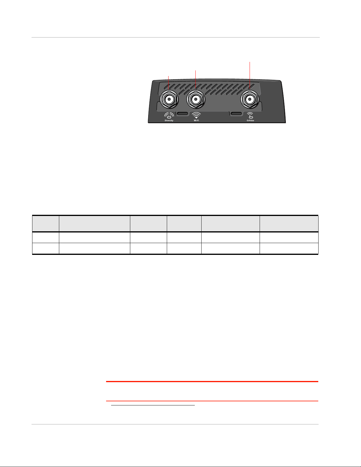
Step 3—Connect the Antennas
Warning: This router is not intended for use close to the human body. Antennas should
be at least 8 inches (20 cm) away from the operator.
The LX40 has two SMA female antenna connectors:
• Cellular antenna connector: Primary receive and transmit antenna connector
• Cellular Diversity antenna connector: LTE MIMO and 3G Diversity
The AirLink LX40 with Wi-Fi also has:
• One reverse polarity SMA male connector for the Wi-Fi antenna.
Sierra Wireless recommends cabling out the antenna.
The LX40 supports 2.4 GHz (2400–2500 MHz) and 5GHz
(4900–5900 MHz) Wi-Fi bands. See Wi-Fi Channels Supported on page 39
for more information.
For regulatory requirements concerning antennas, see Maximum Antenna Gain
on page 48.
Note: The antenna should not exceed the maximum gain specified in RF Exposure on
page 48. In more complex installations (such as those requiring long lengths of cable and/
or multiple connections), you must follow the maximum dBi gain guidelines specified by the
radio communications regulations of the Federal Communications Commission (FCC),
Industry Canada, or your country’s regulatory body.
Note: Take extra care when
attaching the antennas to
the SMA connectors. Finger
tight (approximately 0.6 –
0.8 Nm 5–7 in-lb.) is sufficient and the max torque
should not go beyond
1.1 Nm (10 in-lb.).
To install the antennas:
1. Connect the cellular antenna to the SMA cellular antenna connector.
Mount the cellular antenna so there is at least 20 cm between the antenna
and the user or bystander.
2. Connect a second antenna to the SMA diversity antenna connector.
For 3G networks, the second antenna operates as a diversity antenna, providing a second receive path.
For 4G networks, the second antenna operates as a MIMO antenna, providing
a second receive path and a second transmit path.
3. For Wi-Fi-capable routers, connect the Wi-Fi antenna to the SMA Wi-Fi
connector.
Note: If the antennas are located away from the router, keep the cables as short as
possible to prevent the loss of antenna gain. Route the cables so that they are protected
from damage and will not be snagged or pulled on. There should be no binding or sharp
corners in the cable routing. Excess cabling should be bundled and tied off. Make sure the
cables are secured so their weight will not loosen the connectors from the router over time.
Rev 1 November 2018 16 41112510
Page 17
Installation and Startup
Cellular antenna connector
Diversity antenna connector
Wi-Fi antenna connector
Figure 2-7: Antenna Connectors
Recommended Antenna Separation
The recommended antenna separation is related to the band frequency/
wavelength. To accommodate the shortest frequency/longest wavelength band
supported by the LX40, Sierra Wireless recommends a minimum antenna
separation of 214 mm for best results, and if necessary, a separation of 107 mm
for acceptable results.
Table 2-1: Frequency /Wavelength Range and Recommended Antenna Separation for the
AirLink LX40
Service Wavelength Range for LX40 Frequency
LTE Longest 700 428 214 107
LTE Shortest 2600 115 58 29
(MHz)
Wavelength
(
) (mm)
Best Antenna
Separation (mm) (1/2
Good Antenna
Separation (mm) (1/4
)
Step 4—Connect the Data Cables
The LX40 has the following ports for connecting data cables:
• USB (Micro-AB)
• Ethernet (RJ-45)— Use a Cat 5e or Cat 6 Ethernet cable
Step 5—Connect the Power
The AirLink LX40 comes with a 3 meter (10 ft.) DC power cable. You can also
purchase an optional AC adapter.
The LX40 can also use Power over Ethernet. An Ethernet cable connected to a
compatible
connection to the LX40 power connector (see Figure 2-8 on page 19) is required.
1
network switch or router can supply power to the LX40. No
)
Rev 1 November 2018 17 41112510
Warning: Electrical installations are potentially dangerous and should be performed by
personnel thoroughly trained in safe electrical wiring procedures.
1. The LX40 is a 802.3af Powered Device
Page 18

AirLink LX40 Series Hardware User Guide
The LX40 supports an operating voltage of 7 V–36 V, but because low voltage
standby mode is enabled by default, you must supply more than 9 V at startup.
In cases where both PoE and DC power are connected, PoE will power the LX40
when DC voltage is below 20 V.
If you want to operate the router at a lower voltage, you can change the low
voltage standby settings once the router is up and running. For more information,
refer to the ALEOS Software Configuration User Guide (Services chapter).
Cable Strain Relief
Sierra Wireless recommends using cable strain relief for installations in highvibration environments.
Place the cable strain relief within 200 mm (8 in.) of the LX40 to reduce the mass
of cable supported by the power connector under vibration. Ideally, the strain
relief mounting for the DC cable should be attached to the same object as the
LX40, so both the router and cable vibrate together. The strain relief should be
mounted such that it does not apply additional stress on the power connector.
The cable should not be taut and should not pull the power connector at an angle.
Fusing
For DC installations, Sierra Wireless recommends fusing the power input using a
4 A, fast blow fuse on the V
rating over the operating temperature range.
line, recommended to have no more than ±10% de-
in
Rev 1 November 2018 18 41112510
Page 19

Power Connector on the LX40
For more information, see wiring diagrams on page 20.
For I/O information,
see page 22.
Pin 3 (White)
On/Off (Ignition) control
Pin 1 (Red)
Power
Pin 4 (Green)
GPIO
Pin 2 (Black)
Ground
Figure 2-8: DC Power Cable Connections (Colors indicate DC cable wire colors)
Table 2-2: Power Connector Pin and DC Cable Wires
Installation and Startup
Pin Name DC Cable
Description Type
Wire Color
1 Power Red Main power supply for device
PWR
Note: If you want to turn the LX40 on/off using a control line, Sierra
Wireless strongly recommends that you connect the On/Off control line to
Pin 3 and apply continuous power on Pin 1.
2 Ground Black Main device ground PWR
3 On/Off
control
White For installations where the LX40 is to be turned on/off, use the white wire
connected to Pin 3 in the DC cable. The LX40 is off when this pin is either
open-circuit or grounded, and on when this pin is connected to power. The
LX40 should not be turned off by simply disconnecting the power.
Pin 3 can be connected to an external switch.
Note: If you do not connect pin 3 to a switch, you MUST connect it to the
positive terminal of your power supply or battery. If you are using a Sierra
Wireless AC adapter, the connection is inside the cable.
Note: When the LX40 is using PoE, On/Off control is ignored.
I
Rev 1 November 2018 19 41112510
4 GPIO Green User configurable digital input/output or analog voltage sensing input.
Connect to switch, relay or external device. For more information, see
Step 6—I/O Configuration on page 22 and refer to the ALEOS Software
Configuration User Guide.
I/O
Page 20

AirLink LX40 Series Hardware User Guide
LX40 router
Power
Ignition Sense
I/O
Ground
DC power source
1
3
4
2
7.5 A Fuse
LX40
DC Power Source
2 Ground
4 I/O
1 Power
3 On/Off
4 A fuse
Wiring Diagrams
If you do not use the AC power adapter to power the LX40, you can wire the
supplied DC cable to your power supply. You have various options for wiring
power to the LX40, depending on your application.
Note: If using PoE as a power source, connections to the 4-pin power connector are not
required.
Basic Installation with DC Power
For installations using DC power, connect the wires as shown in the figure below.
You can configure Low voltage disconnect to force the router into Standby mode
when the voltage is low. Voltage is monitored on Pin 1 (red wire).
Figure 2-9: Fixed Installation without I/O
• Pin 1 (Power) —Use the red wire in the DC cable to connect Pin 1 to the
power source. Include a 4 A, fast blow fuse, recommended to have no more
than ±10% de-rating over the operating temperature range, in the input power
line. Sierra Wireless recommends using a continuous (unswitched) DC power
source.
• Pin 2 (Ground)— Use the black wire in the DC cable to connect Pin 2 to
ground. See also Step 2— Mount and Ground the LX40 Chassis on page 11.
• Pin 3 (On/Off control)— Connected to power
Basic Installation with I/O Input Triggered by Standby
Mode
If you want to use the I/O to monitor an external device such as a motion detector,
remote solar panel, or a remote camera, refer to Figure 2-10. You can configure
the I/O line to wake the router up for a configured length of time, and use low
voltage disconnect to put the router in Standby mode if the voltage falls below a
configured value.
Rev 1 November 2018 20 41112510
Page 21

Installation and Startup
LX40 router
Power
Ignition Sense
I/O
Ground
Motion sensor
DC power source
1
3
4
2
7.5 A Fuse
LX40
DC Power Source
2 Ground
4 I/O
1 Power
3 On/Off
4 A fuse
Motion Sensor
Figure 2-10: Fixed Installation with I/O
• Pin 1 (Power) —Use the red wire in the DC cable to connect Pin 1 to the
power source. Include a 4 A, fast blow fuse, recommended to have no more
than ±10% de-rating over the operating temperature range, in the input power
line. Sierra Wireless recommends using a continuous (unswitched) DC power
source.
• Pin 2 (Ground)— Use the black wire in the DC cable to connect Pin 2 to
ground. See also Step 2— Mount and Ground the LX40 Chassis on page 11.
• Pin 3 (On/Off control)— Connected to power
• Pin 4 (GPIO)—Use the green wire for I/O configurations. See Step 6 — I /O
Configuration on page 22.
Rev 1 November 2018 21 41112510
Page 22

AirLink LX40 Series Hardware User Guide
4
Power Connector
Step 6—I/O Configuration
You can use Pin 4 on the LX40 power connector for I/ O configuration.
Figure 2-11: I/O Pin-out for the LX40 Power Connector
You can use the I/O pin as:
· Pulse counter
(See Table 2-3 on page 23 and Figure 2-12 on page 23.)
· Digital input
(See Table 2-3 on page 23 and Figure 2-13 on page 24.)
· High side pull-up/dry contact switch input
(See Table 2-5 on page 25 and Figure 2-14 on page 25.)
· Analog input
(See Table 2-6 on page 26 and Figure 2-15 on page 26.)
· Low side current sink
(See Table 2-7 on page 27 and Figure 2-17 on page 27.)
· Digital outputs/ open drain
(See Table 2-8 on page 28 and Figure 2-18 on page 28.)
Rev 1 November 2018 22 41112510
For more information, refer to the ALEOS Software Configuration User Guide.
Note: You can configure the GPIO Pin 4 in ACEmanager or ALMS to trigger standby
mode, to sink current, or to pull up the voltage. If you are using the I / O line to trigger
standby mode, you cannot configure it to sink current or pull up the voltage. Likewise, if
you are using the I/O line to either sink current or pull up the voltage, you cannot use it to
trigger standby mode.
Note: During bootup, the I/O settings remain in their default state: the internal pull-up
resistor is disabled, and output current sink switch is open. After bootup, any custom I/O
settings are applied. This may take approximately 30 seconds after the gateway is
restarted or powered on.
Page 23

Installation and Startup
LX40
Digital Pulse
Generator
V
in
Internal pull-up
resistor
Off (default)*
Z
in!Nſ
Protection
Circuitry
VLowƊ9
V
HighƋ9
Pin 4 (power connector)
* Configurable on the ACEmanager I/O tab
You can use the I/O pin in conjunction with events reporting to configure the LX40
to send a report when the state of the monitored router changes, for example
when a switch is opened or closed. For more information, refer to the ALEOS
Software Configuration User Guide (Events Reporting chapter).
Pulse Counter
You can use the green wire to connect Pin 4 to a pulse counter. The digital pulse
counter is not available in Standby mode.
Figure 2-12: Digital Input / Pulse Counter
Maximum frequency: 140 Hz
Duty cycle: 20%–80%
Note: Values may vary, depending on signal noise.
Table 2-3: Pulse Counter
Pull-up State Minimum Typ i c a l Maximum
Off Low — — 1.0 V
High 2.7 V — V
in
Digital Input
You can use the green wire to connect Pin 4 to a digital input to detect the state of
a switch, or to monitor an external device such as a motion detector, a remote
solar panel, or a remote camera. Digital input can also be used with the standby
timer.
The primary digital input of Pin 4 on the power connector can be used to wake the
router from standby.
Rev 1 November 2018 23 41112510
Page 24

AirLink LX40 Series Hardware User Guide
LX40
Digital Input
Vin
Internal pull-up
resistor
Off (default)*
Protection
Circuitry
VHighƋ9
Pin 4 (power connector)
* Configurable on the ACEmanager I/O tab
Figure 2-13: Digital Input
Table 2-4: Digital Input
Pull-up State Minimum Typ i c a l Maximum
Off Low — — 1.0 V
High 2.7 V — V
in
Rev 1 November 2018 24 41112510
Page 25

Installation and Startup
*Depending on the load, this value can range from Vin to Vin - 2.5 V.
** Configurable on the ACEmanager I/O tab
LX40
Vin*
Internal pull-up
resistor (10K)
On**
I
Source
= 1.1 mA (Typ)
Protection
Circuitry
Output Off (default)**
Pin 4 (power connector)
High Side Pull-up / Dry Contact Switch Input
You can use the green wire to connect Pin 4 to a dry contact switch. The dry
contact switch is not available in Standby mode.
Figure 2-14: High Side Pull-up / Dry Contact Switch Input
Table 2-5: High Side Pull-up / Dry Contact Switch Input
Minimum Typical Maximum Comments
Source Current 0.6 mA
= 7 V
V
in
V
out
Vin - 2.5 V — V
1.1 mA
= 12 V
V
in
3.5 mA
= 36 V
V
in
in
Analog Input
You can connect Pin 4 on the power connector to an analog sensor. As an analog
input (voltage sensing pin), the router monitors voltage changes in small
increments. This allows you to monitor equipment that reports status as an
analog voltage.
The pin detects inputs of 0.5– 5 V or 0.5 – 10 V referenced to ground. When used
with a sensor to transform values into voltages, the pin can monitor
measurements such as temperatures, sensors, or input voltage.
Using ACEmanager, you can select the range of voltage to be monitored to be
0–5 V or 0– 10 V. For low input voltages, 0–5 V provides better accuracy.
Maximum current the voltage output can
provide (depends on V
The voltage on Pin 4 when the high side
pull-up is enabled (depends on V
power consumption)
)
in
and
in
Rev 1 November 2018 25 41112510
Page 26

AirLink LX40 Series Hardware User Guide
LX40
Vin
Internal pull-up
resistor
Off (default)*
Z
in!Nſ
Protection
Circuitry
Pin 4 (power connector)
Solar panel or battery
Output Off (default)*
+
–
* Configurable on the ACEmanager I/O tab
Microprocessor
CPU
Sample every 250 ms,
Reading from the CPU
Updates UI
Events Reporting
When a reading is received,
based on 20 measurements
when change is significant
or 2.5 minutes has passed
with no change
Pin 4 on the power connector
Analog input
Figure 2-15: Analog Input
Table 2-6: Analog Input
Pull-up Minimum Typ i c al Maximum
Off Analog Input Range 0.5 V — 5 V, 10 V
(configurable)
Analog Input Accuracy -1.5% 0.50% 1.5%
Data sampling is handled by a dedicated microprocessor. In order to filter noisy
signals, twenty measurements are taken over a 250 ms interval. The
measurements are averaged to generate a sample. If the change since the last
sample is significant, a notification is sent to the CPU for updating the current
value displayed in the user interface and for use by Events Reporting.
Changes are considered significant if the change is 200 mV or more (when the
range of monitored voltage is 0–5 V) or 350 mV or more (when the range of
monitored voltage is 0– 10 V). If there has not been a significant change to the
parameter being monitored, the CPU reads a sample every 2.5 minutes, which
detects small changes.
Figure 2-16: Analog Input Sampling and Reading
Note: The same method is used to sample the input voltage and the internal board
temperature for Events Reporting. The significant changes are 300 mV for the input
voltage and 1 ºC for the board temperature.
Rev 1 November 2018 26 41112510
Page 27

Installation and Startup
LX40
Vin
Vin
Internal pull-up
resistor
Off
Protection
Circuitry
Pin 4 (power connector)
External solenoid/relay circuit
ISink = 500 mA (Typ)*
* See Table 2-7 on page 27 for more details.
Low Side Current Sink Output
You can use Pin 4 as a low side current sink; for example, to drive a relay.
Figure 2-17: Low Side Current Sink
Table 2-7: Low Side Current Sink
Pull-up State Minimum Typical Maximum Comments
Off On 300 mA 500 mA 850 mA I_Typical = 25°C
I_Min = 65°C
I_Max = -30°C
Off Off — 0 mA — Vin = 12
Note: The router protection circuitry has a high-impedance (~200 kΩ) path to ground. If
Pin 4 is connected to 12 V, there will be a small current flow (~100 μA) into Pin 4 during
bootup. This flow is countered when the internal pull-up resistor (10 kΩ) becomes active
after bootup. Depending on your application, you may need to install an external pull-up
resistor (10 kΩ) in order to nullify the small input current flow for the first 30 seconds during
bootup.
Rev 1 November 2018 27 41112510
Page 28

AirLink LX40 Series Hardware User Guide
LX40
Vin
Vcc
External Pull-Up
Resistor
Internal pull-up
resistor
Off
Protection
Circuitry
Pin 4 (power connector)
On/Off
Digital Output/Open Drain
Digital output/open drain, used to drive an external digital input, for example, is
available using Pin 4 on the power connector.
Figure 2-18: Digital Output/Open Drain
Table 2-8: Digital Output /Open Drain
Pull-up State Minimum Typica l Maximum Comments
Off Off Open Circuit — — —
Active Low — — 0.5 V 5 mA, 5 V
Step 7—Check the Router Operation
1. When power is supplied to the AirLink LX40 router, it powers up automatically,
as indicated by the flashing LEDs. If it does not turn on, ensure that the:
· Power connector is plugged in and supplying voltage greater than 9 VDC.
Note: Although the LX40 operates in the range 7–36 VDC, low voltage standby mode
is enabled by default. In order to avoid the router powering on in standby mode,
ensure that it is supplied with more than 9 VDC at startup. (You can change the low
voltage standby mode settings once the router is operational. If the Power LED is red,
the router is in standby mode.)
· On/Off control (pin 3) is connected to the battery or power source (see
Step 5—Connect the Power on page 17 for details).
Rev 1 November 2018 28 41112510
Page 29

LED Behavior
Table 2-9: LED Behavior
LED Color / Pattern Description
Power Off No power, or input voltage ≥ 36 VDC or ≤ 7 VDC
Solid Green Power is present.
Solid Red Standby mode
If you want to operate the router using less than 9 V, change the Low Voltage
Standby settings (In ACEmanager, see Services > Power Management).
Note: You can configure the Power LED to flash slowly or turn off during
Low Voltage Standby mode. In ACEmanager, see Services > Power
Management.
Installation and Startup
Solid Amber Entering low power mode or system low level boot.
Flashing Green When you press the Reset button for less than 5 seconds, flashing green
indicates when to release the reset button to reboot the router.
Flashing Red When you press the Reset button for 5 – 20 seconds, flashing red indicates
when to release the Reset button to reset the router to the factory default
settings.
Flashing Amber When you press the Reset button for more than 20 seconds, flashing amber
indicates when to release the Reset button to enter Recovery mode. (See
Recovery Mode on page 33.)
Activity Flashing Green Traffic is being transmitted or received over the WAN interface.
Flashing Red Traffic is being transmitted or received over the serial port. This behavior
Flashing Amber Traffic is being transmitted or received over both the WAN interface and the
Signal Solid Green Good signal (equivalent to 3 –5 bars)
Solid Amber Fair signal (equivalent to 2 bars)
Flashing Amber Poor signal (equivalent to 1 bar)
Flashing Red Inadequate (equivalent to 0 bars)
only appears if the LX40 is configured to display it.
serial port. This behavior only appears if the LX40 is configured to display it.
If possible, Sierra Wireless recommends moving the router to a location with
a better signal.
Sierra Wireless recommends moving the router to a location with a better
signal.
Rev 1 November 2018 29 41112510
Page 30

AirLink LX40 Series Hardware User Guide
Table 2-9: LED Behavior
LED Color / Pattern Description
Note: The quality of the signal strength is measured using the appropriate parameters for the radio technology in use.
Network Solid Green Connected to an LTE network
Solid Amber Connected to a 3G or 2G network
Flashing Green Connecting to the network
Flashing Green
(3 sec. on/1 sec. off)
Flashing Red No network available
Flashing Red / Amber Network Operator Switching is enabled, but the router is unable to locate the
ALL Green LED chase Radio module reconfiguration/firmware update or Network Operator
Amber LED chase ALEOS software update is in progress
Solid Amber ALEOS software update complete
Red LED chase Recovery mode
WAN over Wi-Fi (LX40 is in Wi-Fi client mode)
required firmware. For more information, refer to the ALEOS Software
Configuration User Guide (Admin chapter).
Switching is in progress
Ethernet LEDs
The connector has two LEDs that indicate speed and activity. When looking into
the connector:
• Activity—The right LED indicates the link status:
· Solid—Link
· Blinking Amber—Activity
· Off—No link
• Connection Speed—The left LED indicates the Ethernet connection speed:
· Solid Green— 1000 Mbps (Gigabit)
· Off—10/100 Mbps
Rev 1 November 2018 30 41112510
Page 31

Installation and Startup
Step 8—Configure the Software
You can configure the ALEOS software on the LX40 using:
• ACEmanager (browser-based application)
• AirLink Management Service (cloud-based application)
• AirLink Mobility Manager (unified software platform deployed in the enterprise
data center)
• AT Commands
Configuring with ACEmanager
To access ACEmanager:
1. Connect a laptop to the router with an Ethernet cable.
2. Launch your web browser and go to http://192.168.13.31:9191.
Note: It takes the router from 1 to 2 minutes to respond after power up.
Figure 2-19: ACEmanager login window
3. Enter the default password (printed on the device label) and click Log In.
Note: For system security, ensure that you change the default password as soon as
possible.
4. Refer to the ALEOS Software Configuration User Guide for information on
how to use ACEmanager to configure your LX40.
Configuring with AirLink Management Service
AirLink Management Service (ALMS) allows remote management of all your
routers from one user interface.
Some of its features include:
• Centralized, remote monitoring for all your AirLink routers
• Continuous status monitoring of important health data such as signal strength
• Location monitoring, including world map views
Rev 1 November 2018 31 41112510
Page 32

AirLink LX40 Series Hardware User Guide
• Complete ALEOS reporting and configuration, including historical views of
ALEOS information
• Configure individual routers or use templates to perform batch configurations
of your AirLink routers
• Single-click over-the-air firmware updates to all your routers
• Compatible with all carriers or mobile network operators
To get started, either call your AirLink reseller or visit:
www.sierrawireless.com/ALMS
Configuring with AMM
AirLink Mobility Manager (AMM) is a Network Management solution that enables
simplified management, control and monitoring of connected AirLink routers. AMM
is a licensed, unified software platform deployed in the enterprise data center. It
enables:
• Mobile network and asset management
• Over-the-air registration, configuration and software updates
• Consolidated network view of an entire fleet, in-field applications and mobile
assets, using a virtual dashboard to monitor, report, manage, and troubleshoot all mobile resources as required.
If you require a network management solution deployed in your data center,
contact your Sierra Wireless sales representative for a demonstration of the AMM
capabilities.
Configuring with AT Commands
For a complete list of AT commands, refer to the ALEOS Software Configuration
User Guide.
Reboot the LX40
To reboot the LX40, either:
• On the router, use a tool such as a paper clip or small screwdriver to press
the Reset button for less than 5 seconds. (Release the button when the
Power LED flashes green.) The reset button is recessed approximately 5 mm
(1/4 inch), which prevents casual use of a pen for resetting the router. The
Reset button is small, so ensure that the tool fully contacts the button.
• In ACEmanager, click the Reboot button on the toolbar.
Reset the LX40 to Factory Default Settings
To reset the router to the factory default settings:
• In ACEmanager, go to Admin > Advanced and click the Reset to Factory
Default button.
Rev 1 November 2018 32 41112510
Page 33

Installation and Startup
Note: When you use ACEmanager to reset the router to the factory default settings, some
settings such the user password, network ID, network password, custom APNs, low
voltage standby are preserved by default. However, you can configure the LX40 Reset
Mode to reset all values, including the user password. For more details, refer to the
ALEOS Software Configuration User Guide (Admin chapter).
–Or–
• On the router, press the Reset button for between 5 and 20 seconds.
(Release the button when the Power LED flashes red.)
Once the LEDs resume their normal operating behavior, the reset is
complete.
Warning: Using the Reset button as described above resets all settings to default,
including the user password, no matter what Reset Mode you have configured in ACEmanager. The Reset button can be disabled in ACEmanager if required. Before installation,
please record the default password on the device label and store it in a secure place.
Recovery Mode
If the router fails to boot properly, it automatically enters recovery mode, or, if the
router is unresponsive to ACEmanager input and AT commands, you can
manually put the router into recovery mode.
Recovery mode enables you to update the ALEOS software and return the router
to working order. (For details, refer to the ALEOS Software Configuration User
Guide—Configuring your router chapter.)
To enter Recovery mode manually:
• On the router, press the Reset button for more than 20 seconds. (Release the
button when the Power LED flashes amber.)
To recover the router:
• Update ALEOS using the Recovery mode interface. Once the new ALEOS
version is successfully uploaded and installed, the router reboots and exits
recovery mode. When the process is complete, the ACEmanager login
screen appears.
Note: After the recovery, you need to reload the radio module firmware store and templates.
To exit Recovery mode, if it has been inadvertently entered, do one of the following:
• Press the reset button on the router to reboot it.
• Click the Reboot button on the Recovery screen.
• Wait 10 minutes. If no action is taken within 10 minutes of the device entering
Recovery mode (for example, if the Recovery screen has not been loaded by
the web browser), it automatically reboots and exits Recovery mode.
For more information, refer to the ALEOS Software Configuration User Guide
(Gateway Configuration chapter).
Rev 1 November 2018 33 41112510
Page 34

3: Specifications
This chapter describes the LX40 router specifications.
Certification and Interoperability
Note: All certifications listed below are pending. Some are in progress; others are planned.
Emissions / Immunity • FCC
Safety • CB Scheme
3
• Industry Canada
• UL 60950
Industry Certification
for Vehicles
Environmental
Compliance
GSM/HSPA+
Certifications
• ISO7637-2
• SAE J1455 (Shock & Vibration)
• RoHS 2011/65/EU (RoHS 2)
• WEEE
• REACH
• PTCRB
• GCF-CC
• RED
Mobile Network Operator Certification
Note: Certifications listed below are pending. Some are in progress; others are planned.
• Verizon Wireless
• AT&T
• T-Mobile USA
• Rogers
• Bell Mobility1
• Telus
1
1
1. Certification planned
Rev 1 November 2018 34 41112510
Page 35

Specifications
Network Technology
LTE and HSPA
For a list of supported bands, see Table 3-3 on page 40 and Table 3-4 on
page 40.
Environmental Testing
Test Method Category Description
MIL-STD-810G,
Test method 514.6
MIL-STD-810G,
Test method 516.6,
Procedure 1
MIL-STD-810G,
Test methods
501.5, 502.5
MIL-STD-810G,
Test methods
501.5, 502.5
MIL-STD-810G,
Test method 507.5
Vibration Frequency range: 5 Hz–500 Hz
Spectrum level: 2.24G on all axes for 8 hours/axis
Operating mode: powered on
Mechanical Shock Half-sine 40G, 15–23 ms,
(+/-X, +/-Y, +/-Z directions, 10 times per axis)
Operating mode: powered on
Temperature Rugged category: -30 °C to 65 °C
2-hour soak each temp high/low 3 cycles
ramp <= 3 °C/minute
Operating mode: powered on
Temperature Rugged category: -40 °C to 85 °C
2-hour soak each temp high/low 50 cycles
ramp <= 3 °C/minute
Operating mode: unpowered
Humidity 10 × 48-hour cycles:
• Before starting cycles, condition to 23 °C and
50% relative humidity for 24 hours
• 2-hour ramp to 60 °C (90% humidity), hold 6
hours
• 8-hour ramp down to 30 °C (85% to 90% rela-
tive humidity), hold 8 hours
• After finishing cycles, condition to 23 °C and
50% relative humidity for one hour
Operating mode: powered on
IEC 61000-4-2 Electrostatic
Discharge
IEC 60068-2-32 Free Fall Test 1 m drop height
+/-2 kV, +/-4 kV, +/-6 kV, +/-8 kV (Contact and Air)
+/-15 kV (Air at antenna connector)
Operating mode: powered on
6 drops onto concrete, 2 per axis: X, Y, Z
Operating mode: unpowered
Rev 1 November 2018 35 41112510
Page 36

AirLink LX40 Series Hardware User Guide
Test Method Category Description
IEC 60068-2-70
Part 2, Test Xb
ISTA 2A 2001,
test categories 1,
4, 5, & 6
Marking
Package In shipping packaging.
Host Interfaces
Antenna
connectors
USB
• On all units:
• Cellular SMA
• SMA Diversity
• On units with Wi-Fi option:
• One RP SMA Wi-Fi
Note: Do not use the USB port in a potentially explosive environment.
• USB 2.0 Micro-AB connector complies with USB Version 2.0
for high speed operation
• Can be configured to operate in one of two modes:
• Virtual Ethernet Port: The LX40 behaves as if the PC were
connected to an Ethernet port, allowing access to the Internet
and the LX40’s internal web server. This is the default setting.
• Virtual Serial Port: The LX40 behaves as if it was
connected to a standard serial port. The primary use of this
interface is for the AT command line interface of ALEOS and
for diagnostic access to the radio module.
By default, the USB port is configured as a virtual Ethernet port.
• A Windows driver must be installed on the PC in order to
support USB use. The drivers are available for download on
Sierra Wireless’ support web site:
source.sierrawireless.com/resources/airlink/software_downloads/airlink_usb_driver/
• The ALEOS Software Configuration User Guide contains the
details of USB mode configuration and driver installation.
• Sierra Wireless recommends you:
• Use a USB 2.0 cable
• Connect directly to your computer for best throughput.
The markings are rubbed with water for 10 cycles,
then with lubricating oil for 10 cycles.
Operating mode: unpowered
Cargo vibration and drop test.
Ethernet • 10/100/1000 Base-T RJ-45 Ethernet
• Auto-crossover support
• Auto-negotiation detects the speed of the connecting device
Rev 1 November 2018 36 41112510
Page 37

Specifications
SIM Card Interface
The LX40 has one 6-pin SIM socket for a mini-SIM (2FF) SIM card, operated at
1.8 V/3.3 V. This interface is compliant with the applicable 3GPP standards for
USIM.
Mechanical Specifications
For mechanical drawings, dimensions, and weight, see Mechanical Specifications
on page 46.
• Housing—The LX40 is made of rugged injection-molded plastic.
• RoHS2—The LX40 complies with the Restriction of Hazardous Substances
Directive 2011/65/EU (RoHS2). This directive restricts the use of hazardous
materials in the manufacture of various types of electronic and electrical
equipment.
Screw Torque Settings
Antennas: Finger tight (5– 7 in-lb) is sufficient. The max torque should not go
beyond 1.1 N-m (10 in-lb).
Operating Voltage
By default, the router is configured to enter Standby mode at 9 V. If you want to
operate the router at less than 9 volts, power it on using at least 9 V, launch
ACEmanager, go to Services > Power Management and adjust the Standby mode
settings.
The maximum ripple voltage to guarantee analog input accuracy must be
100 mVpp.
Power Specifications
Power over Ethernet: 13 W, Type 1 Power Device, compatible with IEEE 802.3af.
Table C-1: DC Power Supply Specifications
Pin Name Specification Parameter Minimum Maximum
1 VCC Voltage range VCC 7 V 36 V
Rev 1 November 2018 37 41112510
Page 38

AirLink LX40 Series Hardware User Guide
Table C-2: On/Off Control Specifications
Pin Name Current Sink Specification Parameter Minimum Maximum
3 On/Off control,
Ignition Sense
(Input only)
Note: If you do not connect this pin to the ignition, you MUST connect it to the positive terminal of your power supply or
battery. The device looks for a qualified voltage on this pin as part of the power up sequence. If it doesn’t see it, the
device will not turn on. If you are using a Sierra Wireless AC power adapter, the connection is inside the cable.
Note: The Pin 3 connection for On/Off control is not required when using PoE.
240 kΩ Input low state voltage
(maximum)
Input high state voltage
(minimum guaranteed)
V
IL
V
IH
— 1.0 V
2.5 V V
in
Protocols
• Network: TCP/IP, UDP/ IP, DNS
• Routing: NAT, Host Port Routing, DHCP, PPPoE, VLAN, VRRP, Reliable
Static Route
• Applications: SMS, Telnet/SSH, Reverse Telnet, SMTP, SNMP, SNTP
Rev 1 November 2018 38 41112510
Page 39

Wi-Fi Performance
Specifications
Technology Frequency MIMO
802.11n 2.4 GHz 1 × 1 72 Mbps
5 GHz 1 × 1 100 Mbps 150 Mbps
802.11ac 5 GHz 1 × 1 87 Mbps 200 Mbps 433 Mbps
a. Theoretical maximum performance. Actual data rates vary.
20 MHz
a
40 MHz
a
80 MHz
Wi-Fi Channels Supported
2.4 GHz 1 - 2.412 GHz
2 - 2.417 GHz
3 - 2.422 GHz
4 - 2.427 GHz
5 - 2.432 GHz
6 - 2.437 GHz
7 - 2.442 GHz
8 - 2.447 GHz
9 - 2.452 GHz
10 - 2.457 GHz
11 - 2.462 GHz
a
5 GHz Ch. 36 (5.180 GHz) 20 MHz, 20/40 MHz, 80 MHz
Ch. 40 (5.200 GHz) 20 MHz, 20/40 MHz, 80 MHz
Ch. 44 (5.220 GHz) 20 MHz, 20/40 MHz, 80 MHz
Ch. 48 (5.240 GHz) 20 MHz, 20/40 MHz, 80 MHz
Ch. 149 (5.745 GHz) 20 MHz, 20/40 MHz, 80 MHz
Ch. 153 (5.765 GHz) 20 MHz, 20/40 MHz, 80 MHz
Ch. 157 (5.786 GHz) 20 MHz, 20/40 MHz, 80 MHz
Ch. 161 (5.805 GHz) 20 MHz, 20/40 MHz, 80 MHz
Ch. 165 (5.825 GHz) 20 MHz
Rev 1 November 2018 39 41112510
Page 40

AirLink LX40 Series Hardware User Guide
Radio Frequency Bands
To determine which radio module your gateway has, refer to the label on the
bottom of the gateway, or in ACEmanager, go to Status > About, and check the
Radio Module Type field.
Note: All carrier radio module firmware support indicated in Ta bl e 3- 3, Table 3-4,
Table 3-5, Table 3-6 and Table 3 -7 is provisional.
Table 3-3: LX40 Radio Module WP7601 North America and EMEA
Radio Technology Module Firmware Band Frequencies
LTE Band 4 Tx: 1710 – 1755 MHz
Verizon Wireless
Rx: 2110–2155 MHz
Band 13 Tx: 777–787 MHz
Rx: 746–756 MHz
Table 3-4: LX40 Radio Module WP7603 North America
Radio
Technology
LTE Band 2 Tx: 1850 – 1910 MHz
Module Firmware Band Frequencies
Generic AT&T
Rx: 1930– 1990 MHz
Band 4 Tx: 1710 – 1755 MHz
Rx: 2110–2155 MHz
Band 5 Tx: 824 –849 MHz
Rx: 869– 894 MHz
Band 12 Tx: 699–716 MHz
Rx: 729 –746 MHz
WCDMA Band 2 Tx: 1850–1910 MHz
Rx: 1930– 1990 MHz
Band 4 Tx: 1710 – 1755 MHz
Rx: 2110–2155 MHz
Band 5 Tx: 824 –849 MHz
Rx: 869– 894 MHz
Rev 1 November 2018 40 41112510
Page 41

Table 3-5: LX40 Radio Module WP7607 EMEA
Specifications
Radio
Technology
LTE Band 1 Tx: 1920 – 1980 MHz
Module Firmware Band Frequencies
Generic
Rx: 2110– 2170 MHz
Band 3 Tx: 1710–1785 MHz
Rx: 1805–1880 MHz
Band 7 Tx: 2500–2570 MHz
Rx: 2620–2690 MHz
Band 8 Tx: 880–915 MHz
Rx: 925 –960 MHz
Band 20 Tx: 832–862 MHz
Rx: 791 –821 MHz
Band 28 Tx: 703–748 MHz
Rx: 758 –803 MHz
WCDMA Band 1 Tx: 1920 – 1980 MHz
Rx: 2110– 2170 MHz
Band 8 Tx: 880–915 MHz
Rx: 925–960 MHz
GSM/GPRS/
EDGE
E-GSM 900 Tx: 880–915 MHz
Rx: 925–960 MHz
DCS 1800 Tx: 1710–1785 MHz
Rx: 1805–1880 MHz
Rev 1 November 2018 41 41112510
Page 42

AirLink LX40 Series Hardware User Guide
Table 3-6: LX40 Radio Module WP7609 Australia and New Zealand
Radio
Technology
LTE Band 1 Tx: 1920–1980 MHz
Module Firmware Band Frequencies
Generic
Rx: 2110– 2170 MHz
Band 3 Tx: 1710–1785 MHz
Rx: 1805–1880 MHz
Band 5 Tx: 824– 849 MHz
Rx: 869–894 MHz
Band 7 Tx: 2500–2570 MHz
Rx: 2620–2690 MHz
Band 8 Tx: 880– 915 MHz
Rx: 925 –960 MHz
Band 28 Tx: 703–748 MHz
Rx: 758 –803 MHz
WCDMA Band 1 Tx: 1920–1980 MHz
Rx: 2110– 2170 MHz
Band 5 Tx: 824– 849 MHz
Rx: 869– 894 MHz
Band 8 Tx: 880– 915 MHz
Rx: 925–960 MHz
Table 3-7: LX40 Radio Module WP7702 Worldwide
Radio
Technology
LTE Band 1 Tx: 1920–1980 MHz
Module Firmware Band Frequencies
Generic
Rx: 2110– 2170 MHz
Band 2 Tx: 1850 – 1910 MHz
Rx: 1930– 1990 MHz
Band 3 Tx: 1710 – 1785 MHz
Rx: 1805–1880 MHz
Band 4 Tx: 1710 – 1755 MHz
Rx: 2110–2155 MHz
Band 5 Tx: 824 – 849 MHz
Rx: 869–894 MHz
Rev 1 November 2018 42 41112510
Page 43

Table 3-7: LX40 Radio Module WP7702 Worldwide
Specifications
Radio
Technology
Module Firmware Band Frequencies
Generic
Band 8 Tx: 880 – 915 MHz
Rx: 925–960 MHz
Band 12 Tx: 699–716 MHz
Rx: 729 –746 MHz
Band 13 Tx: 777–787 MHz
Rx: 746 –756 MHz
Band 17 Tx: 704–716 MHz
Rx: 734 –746 MHz
Band 18 Tx: 815–830 MHz
Rx: 860 –875 MHz
Band 19 Tx: 830–845 MHz
Rx: 875 –890 MHz
Band 20 Tx: 832–862 MHz
Rx: 791 –821 MHz
Band 26 Tx: 814–849 MHz
Rx: 859 –894 MHz
Band 28 Tx: 703–748 MHz
Rx: 758 –803 MHz
GSM/GPRS GSM 850 Tx: 824 – 849 MHz
Rx: 869– 894 MHz
E-GSM 900 Tx: 880– 915 MHz
Rx: 925–960 MHz
DCS 1800 Tx: 1710–1785 MHz
Rx: 1805–1880 MHz
PCS 1900 Tx: 1850– 1910 MHz
Rx: 1930–1990 MHz
Rev 1 November 2018 43 41112510
Page 44

AirLink LX40 Series Hardware User Guide
Radio Module Conducted Transmit Power
The following tables provide radio module conducted transmit power
specifications. The radio module type is printed on the label on the bottom of the
router and is available in ACEmanager (Status > About).
Table 3-8: Radio Module WP7601 Conducted Transmit Power
Band Conducted Tx
Power (dBm)
LTE
Bands 4, 13 +23±1 Connectorized (Class 3)
Notes
Table 3-9: Radio Module WP7603 Conducted Transmit Power
Band Conducted Tx
Power (dBm)
LTE
Bands 2, 4, 5, 12 +23±1 Connectorized (Class 3)
WCDMA
Band 2
Band 4
Band 5 (UMTS 850 12.2 kbps)
+23±1 Connectorized (Class 3)
Notes
Table 3-10: Radio Module WP7607 Conducted Transmit Power
Band Conducted Tx
Power (dBm)
Notes
LTE
Bands 1, 3, 7, 8, 20, 28 +23±1 Connectorized (Class 3)
WCDMA
Bands 1, 8 +23±1 Connectorized (Class 3)
GSM/GPRS/EDGE
E-GSM 900 +33±1 GMSK mode (Class 4)
+27±1 8PSK mode (Class E2)
DCS 1800 +30±1 GMSK mode (Class 1)
+26±1 8PSK mode (Class E2)
Rev 1 November 2018 44 41112510
Page 45

Table 3-11: Radio Module WP7609 Conducted Transmit Power
Specifications
Band Conducted Tx
Power (dBm)
LTE
Bands 1, 3, 5, 7, 8, 28 +23±1 Connectorized (Class 3)
WCDMA
Bands 1, 5, 8 +23±1 Connectorized (Class 3)
Notes
Table 3-12: Radio Module WP7702 Conducted Transmit Power
Band Conducted Tx
Power (dBm)
LTE
Bands 1, 2, 3, 4, 5, 8, 12, 13, 17, 18,
19, 20, 26, 28
GSM/GPRS/EDGE
GSM 850 +32±1 GMSK mode (Class 4)
E-GSM 900 +32±1 GMSK mode (Class 4)
+23±1 Connectorized (Class 3)
+27±1 8PSK mode (Class E2)
Notes
+27±1 8PSK mode (Class E2)
DCS 1800 +29±1 GMSK mode (Class 1)
+26±1 8PSK mode (Class E2)
PCS 1900 +29±1 GMSK mode (Class 1)
+26±1 8PSK mode (Class E2)
Rev 1 November 2018 45 41112510
Page 46

AirLink LX40 Series Hardware User Guide
Front view
Weight: 0.76 kg (1.68 lb.)
Top view
79 mm
(3 1/8 in.)
103 mm (4 1/16 in.)
111 mm (4 3/8 in.)
25 mm
(1 in.)
Mechanical Specifications
Figure 3-1: LX40 Mechanical Specifications
Rev 1 November 2018 46 41112510
Page 47

4: Regulatory Information
Important Information for North American Users
Note: This equipment has been tested and found to comply with the limits for a Class B digital
device, pursuant to part 15 of the FCC Rules. These limits are designed to provide reasonable
protection against harmful interference in a residential installation. This equipment generates,
uses and can radiate radio frequency energy and, if not installed and used in accordance with
the instructions, may cause harmful interference to radio communications. However, there is no
guarantee that interference will not occur in a particular installation. If this equipment does
cause harmful interference to radio or television reception, which can be determined by turning
the equipment off and on, the user is encouraged to try to correct the interference by one or
more of the following measures:
• Reorient or relocate the receiving antenna.
• Increase the separation between the equipment and receiver.
• Connect the equipment into an outlet on a circuit different from that to which the receiver is
connected.
• Consult the dealer or an experienced radio/TV technician for help.
4
Warning: Changes or modifications to this device not expressly approved by Sierra Wireless
could void the user's authority to operate this equipment.
Rev 1 November 2018 47 41112510
Page 48

AirLink LX40 Series Hardware User Guide
RF Exposure
In accordance with FCC/IC requirements of human exposure to radio frequency
fields, the radiating element shall be installed such that a minimum separation
distance of 20 cm should be maintained from the antenna and the user's body.
Warning: This product is only to be installed by qualified personnel.
To comply with FCC/IC regulations limiting both maximum RF output power and
human exposure to RF radiation, the maximum antenna gain must not exceed the
specifications listed below for the device used.
Maximum Antenna Gain
The antenna gain must not exceed the limits and configurations shown in the
following tables:
Table 4-1: WP7601 Maximum Antenna Gain
FCC ID/IC Number
N7NWP76A 2417C-WP76A
Device Frequency Band
AirLink LX40 4 6
13 6
Maximum Antenna Gain (dBi)
Table 4-2: WP7603 Maximum Antenna Gain
FCC ID/IC Number
N7NWP76C 2417C-WP76C
Device Frequency Band
AirLink LX40 2 6
4 6
5 6
12 6
Maximum Antenna Gain (dBi)
Rev 1 November 2018 48 41112510
Page 49

Table 4-3: WP7607/7609 Maximum Antenna Gain
FCC ID/IC Number
N7NWP76C 2417C-WP76C
Regulatory Information
Device Frequency Band
Maximum Antenna Gain (dBi)
AirLink LX40 1 Must not exceed antenna gains due to RF
exposure and ERP/EIRP limits, as listed in
3
the module’s FCC grant.
7
8
20
28
Table 4-4: WP7702 Antenna Gain Specifications
FCC ID/IC Number
N7NWP77B 2417C-WP77B
Maximum antenna gain (dBi)
Device Frequency Band
AirLink LX40 2 9 8
b
4
5 7 6
Standalone Collocated
6 6
a
12 6 6
13 6 6
c
17
6 6
26 7 6
GSM 850 4 3
PCS 1900 3 3
a. Antenna gain limit when module collocated with Wi-Fi/Wimax/BT radios
b. B4— CAT-M1 only
c. B17 — CAT-NB1 only
Table 4-5: WP76XX/WP7702 Collocated Radio Transmitter
Specifications
Device Technology Frequency (MHz) EIRP Limit (dBm)
AirLink LX40 WLAN 2400–2500 25
5150–5850 27
Rev 1 November 2018 49 41112510
Page 50

AirLink LX40 Series Hardware User Guide
WEEE Notice
If you purchased your AirLink LX40 in Europe, please return it to your dealer or
supplier at the end of its life. WEEE products may be recognized by their wheeled
bin label on the product label.
Rev 1 November 2018 50 41112510
Page 51

A: Accessories
12
3
4
Power connector (end view)
Power connector housing (side view)
Pin Wire color Open
1
2
3
4
Red
Black
White
Green
3048 mm (10 ft.) core cable
Power connector housing
Warning label
Male housing
Female crimp terminals
DC Power Cable (Black Connector)
Table A-1: DC Power Cable
DC Power Cable
Part Number 2000522
Product Release 2016
Components:
1 UL2464 20 AWG × 4 core cable
4 Molex female crimp terminals /AWG 20-24, 250V, 5 A max, phosphor bronze
tin-plated (part number 43030-0001)
1 Molex male 2×2P Ph: 3.0 mm housing, 250V, 5 A max, PA65 black
UL94V-O (part number 43025-0408)
A
Rev 1 November 2018 51 41112510
Figure A-1: DC Cable Specifications
Page 52

AirLink LX40 Series Hardware User Guide
AC Power Adapter (Black Connector)
Table A-2: AC Power Adapter
AC Power Adapter
Part Number 2000579
Product Release 2016
AC Power Adapter Input
Table A-3: Input Specifications
Input
Input Voltage 90 VAC 100–240 VAC 264 VAC
Input Frequency 47 Hz 50 / 60 Hz 63 Hz
Minimum Typical Maximum
Note: Input voltage range is 90 VAC to 264 VAC.
Maximum input current is 500 mA at 100– 240 VAC.
Inrush current will not exceed 75 A at 100–240 VAC input and maximum load from a
cold start at 25°C.
AC Power Adapter
Table A-4: AC Power Adapter Output Specifications
Minimum Typ ical Maximum Test conditions
Output Voltage 11.4 VDC 12.0 VDC 12.6 VDC 0 ~ 1.5 A loading
Output
Rev 1 November 2018 52 41112510
Page 53

Accessories
AC Power Adapter Environmental Specifications
Table A-5: AC Power Adapter Environmental Specifications
Operating
Operating Temperature 0°C ~ 40°C (operates normally)
Relative Humidity 10% ~ 90%
Altitude Sea level to 2,000 meters
Vibration
Non-operating
Storage Temperature -30°C ~ 70°C
Relative Humidity 10% ~ 90%
Vibration and Shock MIL-STD-810D, method 514
1.0 mm, 10– 55 Hz, 15 minutes per cycle for each axis (X, Y, Z)
AC Power Adapter Reliability and Quality Control
AC Power Adapter MTBF
When the power supply is operating within the limits of this specification, the
MTBF is at least 200,000 hours at 25°C (MIL-HDBK-217F).
AC Power Adapter Safety Standards
The power supply is certified with the following international regulatory standards:
Table A-6: AC Power Adapter Safety standards
Regulatory
Agency
Country or
Region
Certified Standard
UL USA Approved UL60950-1
GS Europe Approved EN60950-1
CE Europe Approved EN60950-1
SAA Australia Approved AS/NZS 60950
CCC China Approved GB4943
CUL Canada Approved CSA C22.2 NO.60950-1
AC Power Adapter EMC Standards
The power supply meets the radiated and conducted emission requirements for
EN55022, FCC Part 15, Class B, GB9254.
Rev 1 November 2018 53 41112510
Page 54

AirLink LX40 Series Hardware User Guide
AC Power Adapter Hazardous Substances
• EU Directive 2011/65/EU “RoHS”
• EU Directive 2012/19/EU “WEEE”
• REACH
AC Power Adapter Energy Efficiency
The AC adapter complies with International Efficiency Levels, as shown in
Table A-7.
Table A-7: AC Adapter Energy Efficiency
Supplied Input No-load Power
Consumption
115 VAC, 60 Hz Less than 0.1 W Greater than 85% VI
230 VAC, 50 Hz Less than 0.3 W Greater than 80.4% V
Average Active
Mode Efficiency
International
Efficiency Level
Rev 1 November 2018 54 41112510
Page 55

Index
A
AC power adapter, specifications, 52
Accessories, 9
ACEmanager, 31
AirLink Management Service, 31
ALEOS software, 31
AMM, 32
Analog input, 25
Antenna
Connecting, 16
Gain, 48
Maximum gain, 48
Recommended separation, 17
AT commands, 32
C
Cables, connecting, 17
Certification
Mobile Network Operator, 34
Communication
AT commands, using, 32
Command line prompt, using, 28
Conducted transmit power, 44
Configuring the router
AirLink Management Service, 31
AT commands, 32
Current sink, 27
D
DC power cable
Specifications, 51
Wires, 19
Digital I/O specifications, 38
Digital output, 28
Digital output/open drain, 28
E
Ethernet, LEDs, 30
F
Features, 7
Fusing, 18
G
I/O auxiliary connector, 22
Input
Analog, 25
Dry contact switch, 25
Ignition switch, 23
Installation
Connect data cables, 17
Connect power cable, 17
Connecting antennas, 16
Fixed (with I/O), 20
Fixed (without I/O), 20
Overview, 10
Tools and materials required, 10
IP address, obtaining with command line prompt, 28
L
LED
Description of LED, 28
Ethernet, 30
Low side current sink output, 27
LTE, bands supported, 35
M
MIMO, 16
Mounting
On DIN rail, 13, 15
MTBF
AC adapter, 53
O
Open drain, 28
Operating voltage, 37
Output, digital, 28
P
Pinging the router with command line prompt, 28
Power
Connecting, 17
Connector, 17
input specifications, 37
power supply specifications, 37
Power consumption, sample scenarios, 9
Protocols, 38
Pull-up resistor, 25
Pulse counter, 23
Grounding the chassis, 12
H
Host Interfaces, 36
I
I / O Configuration, 22
R
Rebooting, 32
Recovery mode, 33
Regulatory information, 47
Regulatory specifications, 53
Reset to factory default settings, 32
RF exposure, 48
RF specifications, 16
Rev 1 November 2018 55 41112510
Page 56

AirLink LX40 Series Hardware User Guide
S
Screw Torque, 37
Software, configure, 31
Specifications, 34
Environmental, 34
Regulatory, 53
RF, 16
Standards, regulatory, 53
T
Tools required for install, 10
V
Voltage, input and ripple range, 37
W
Warranty, 9
WEEE, 50
Wi-Fi performance, 39
Wiring diagrams, 20
Rev 1 November 2018 56 41112510
 Loading...