

Sierra InnovaMass 241i, InnovaMass i Series, InnovaMass 240i, InnovaMass 24i-IM Instruction Manual

InnovaMass® iSeries
Models 240i & 241i
Vortex Volumetric Flow &
Multivariable Mass Vortex Flow Meters
Instruction Manual
Part Number: 24i-IM
Version D, November 2016

GLOBAL SUPPORT LOCATIONS: WE ARE HERE TO HELP!
For Global Service Centers, go to
http://www.sierrainstruments.com/facilities.html
CORPORATE HEADQUARTERS
5 Harris Court, Building L Monterey, CA 93940
Phone (831) 373-0200 (800) 866-0200 Fax (831) 373-4402
info@sierrainstruments.com
www.sierrainstruments.com
EUROPE HEADQUARTERS
Bijlmansweid 2 1934RE Egmond aan den Hoef
The Netherlands
Phone +31 72 5071400 Fax +31 72 5071401
sales@sierrainstruments.nl
ASIA HEADQUARTERS
Second Floor Building 5, Senpu Industrial Park
25 Hangdu Road Hangtou Town
Pu Dong New District, Shanghai, P.R. China
Postal Code 201316
Phone: + 8621 5879 8521 Fax: +8621 5879 8586
IMPORTANT CUSTOMER NOTICE- OXYGEN SERVICE
Unless you have specifically ordered Sierra’s optional O2 cleaning, this flow meter may not be fit for oxygen
service. Sierra Instruments, Inc., is not liable for any damage or personal injury, whatsoever, resulting from
the use of Sierra Instruments standard mass flow meters for oxygen gas. You are responsible for cleaning
the mass flow meter to the degree required for your oxygen flow application. However, some models can
only be properly cleaned during the manufacturing process.
© COPYRIGHT SIERRA INSTRUMENTS 2015
No part of this publication may be copied or distributed, transmitted, transcribed, stored in a retrieval system,
or translated into any human or computer language, in any form or by any means, electronic, mechanical,
manual, or otherwise, or disclosed to third parties without the express written permission of Sierra
Instruments. The information contained in this manual is subject to change without notice.
TRADEMARKS
InnovaMass®, qTherm®, Dial-a-Gas™, Dial-a-Pipe™, MassBalance™ and Raptor II™ are trademarks of
Sierra Instruments, Inc. Other product and company names listed in this manual are trademarks or trade
names of their respective manufacturers.
2
Get detailed instructions on the Smart Interface Portal (SIP) software in the Smart
Interface Portal instruction manual.
Table of Contents
Chapter 1: Introduction ............................................................................................................................. 7
Chapter 2: Installation Installation Overview ......................................................................................... 13
Chapter 3: Operation & Programming .................................................................................................... 34
Chapter 4: Troubleshooting & Repair ...................................................................................................... 82
Appendix A: Product Specifications ....................................................................................................... 85
Appendix B: Flow Meter Calculations ..................................................................................................... 97
Appendix: C Glossary ............................................................................................................................. 99
Appendix D: ATEX and IECEx Certified EX Units ................................................................................. 102
Appendix E: Warranty Policy ................................................................................................................ 115
3

Warnings and Cautions
Symbol Key
Symbol
Symbol
Meaning
Descripition
Warning
This statement appears with information that is important to
protect people and equipment from damage. Pay very close
attention to all warnings that apply to your application.
Caution
This statement appears with information that is important for
protecting your equipment’s performance. Read and follow all
cautions that apply to your application.
Note and Safety Information
We use caution and warning statements throughout this book to draw your attention
to important information.
General Safety Information
We use caution and warning statements throughout this book to draw your
attention to important information.
Warning!
Consult the flow meter nameplate for specific flow meter approvals before any hazardous
location installation.
Hot tapping must be performed by a trained professional. U.S. regulations often require a
hot tap permit. The manufacturer of the hot tap equipment and/or the contractor
performing the hot tap is responsible for providing proof of such a permit.
All flow meter connections, isolation valves and fittings for cold/hot tapping must have
the same or higher pressure rating as the main pipeline.
For insertion flow meter installations, an insertion tool must be used for any installation
where a flow meter is inserted under pressure greater than 50 psig.
To avoid serious injury, DO NOT loosen a compression fitting under pressure.
To avoid potential electric shock, follow National Electric Code or your local code when
wiring this unit to a power source. Failure to do so could result in injury or death. All AC
4

power connections must be in accordance with published CE directives. All wiring
procedures must be performed with the power off.
Before attempting any flow meter repair, verify that the line is not pressurized. Always
remove main power before disassembling any part of the mass flow meter.
When using toxic or corrosive gases, purge the line with inert gas for a minimum of four
hours at full gas flow before installing the flow meter.
Caution!
Calibration must be performed by qualified personnel. Sierra strongly recommends that
you return your flow meter to the factory for calibration.
In order to achieve accurate and repeatable performance, the flow meter must be installed
with the specified minimum length of straight pipe upstream and downstream of the flow
meter’s sensor head.
For insertion flow meter installations, the sensor alignment pointer must point
downstream in the direction of flow.
The AC wire insulation temperature rating must meet or exceed 85°C (185°F)
Receipt of System Components
When receiving a Sierra mass flow meter, carefully check the outside
damage incurred in shipment. If the carton is damaged, notify the local carrier and
submit a report to the factory or distributor. Remove the packing slip and check that all
ordered components are present. Make sure any spare parts or accessories are not
discarded with the packing material. Do not return any equipment to the factory
without first contacting Sierra Customer Service
packing
carton for
.
Technical Assistance
If you encounter a problem with your flow meter, review the configuration
information for each step of the installation, operation, and setup procedures.
Verify that your settings and adjustments are consistent with factory
recommendations. Installation and troubleshooting information can be found in the
Chapter 2 (Installation) and Chapter 4 (Troubleshooting) of this manual.
If the problem persists after following the troubleshooting procedures outlined in
Chapter 4 of this manual, contact Sierra Instruments by fax or by e-mail (see inside
front cover). For urgent phone support you may call (800) 866-0200 or (831) 373-0200
between 8:00 a.m. and 5:00 p.m. PST. In Europe, contact Sierra Instruments Europe at
+31 72 5071400
5879 8521.
information:
. In the Asia-Pacific region, contact Sierra Instruments Asia at +
When contacting Technical Support, make sure to include this
8621
5

The flow range, serial number, and Sierra order number (all marked
on the meter nameplate)
The software version (visible at start up)
The problem you are encountering and any corrective action taken
Application information (gas, pressure, temperature and piping
configuration)
Using This Manual
This manual provides information needed to install and operate both the 240i Inline and 241i
Insertion InnovaMass vortex flow meters.
Chapter 1 includes the introduction and product description
Chapter 2 provides information needed for installation
Chapter 3 describes system operation and programming
Chapter 4 covers troubleshooting and repair
Appendix A - Product Specifications
Appendix B - Flow Meter Calculations
Appendix C – Glossary
Appendix D - ATEX and IECEx Certified EX Units
Appendix E – Warranty Policy
Register Your Product Today
Warranty Statement
All Sierra products are warranted to be free from defects in material and workmanship and will be
repaired or replaced at no charge to Buyer, provided return or rejection of product is made within
a reasonable period but no longer than one (1) year for calibration and non-calibration defects,
from date of delivery. To assure warranty service, customers must register their products online
on Sierra’s website. Online registration of all of your Sierra products is required for our warranty
process.
Read complete warranty policy at www.sierrainstruments.com/warranty
Register Warranty Online
Register now at www.sierrainstruments.com/register. Learn more about Sierra’s warranty policy
at www.sierrainstruments.com/warranty
6

Chapter 1: Introduction
InnovaMass. Reinvented.
In the 1990s, Sierra designed and introduced InnovaMass, the first multivariable mass vortex flow
meter in the world. Through a single process connection, InnovaMass now empowered customers
with mass flow rate, volumetric flow rate, density, temperature and
pressure. Five instruments in one.
InnovaMass’ innovative new features introduced a welcome force-multiplier. With five high
accuracy measurements available from a single device, total cost-of-ownership plummeted.
Lower initial cost, less complex installation, and reduced maintenance costs contributed to
significant customer savings.
Today, with the latest hyper-fast microprocessors, robust software applications, and our new
automated state-of-the-art flow calibration facility, the completely re-designed InnovaMass
240i/241i “iSeries” delivers precision, performance, and application flexibility never before
possible.
The Vortex “i” Series Introduces Comprehensive Flow Energy Management
To meet process control demands, flow energy in the form of steam, compressed air, natural gas
and water must be measured and managed with greater precision than ever before. Increased
control over resulting flow energy costs drives increased productivity and competitiveness.
The reinvented InnovaMass 240i and 241i delivers a revolution in flow energy management with
these new iSeries features:
Raptor II microprocessor is 10x faster to run robust software applications
Field diagnostics, validation, and adjustment through onboard Smart Interface Portal
Rapid update of latest features with field firmware upgrade capability
FloPro™ software application improves point-velocity accuracy for insertion version
Complete suite of digital communications for turnkey networking & automation
Patented MassBalance™ sensor in tandem with Raptor II for mechanical and digital
signal processing breakthroughs
240i Inline/241i Insertion
Mass or volumetric flow monitoring of gases, liquids and steam
Measures five process variables with one process connection: mass flow, volumetric
flow, density, pressure, temperature
Insertion version for 2 inch (50.8 mm) or greater; inline to 8 inches (DN 200)
Accuracy of up to 0.7% of reading; temperature to 392 °F (200 °C); pressure to 750 psig
(50 barg)
Raptor II OS flow engine builds and measures complex liquid and gas mixtures
Raptor II OS and MassBalance technology extends range down to Reynold’s numbers
below 5000
Smart Interface Portal assures field validation and allows for easy configuration
Datalogging capability
Dial-A-PipeTM: Change pipe size in the field
Dial-A-FluidTM: Change fluid in the field
Three configurable 4-20 outputs
7
Multiple languages
Figure B: Out Of Phase Vibration
Signals
HART, Modbus, Profibus DP, Foundation Fieldbus, USB, RS-232
AGA-8 density equations
Approvals: CE, cFMus, ATEX, PED, IECEx
Raptor II OS Flow Engine Powers Advanced Field Flexibility
Originally developed as the operating system for our QuadraTherm thermal mass flow meter,
Raptor II OS is the “flow-engine” inside every InnovaMass iSeries vortex meter. Raptor II uses
advanced digital signal processing and proprietary mathematical algorithms to enhance the flow
signal, while also calculating the thermodynamic properties of the gas, liquid or steam being
measured in real-time.
Raptor II accomplishes the following:
Easily manages all five process variables in real time
It has Apps: Robust field flexibility with applications like FloPro, Dial-A-Pipe, Dial-A-
Fluid, and ValidCal Diagnostics
Allows for field firmware upgrades of latest features and improvements
Real-time adjustments for temperature, pressure, density, or compressibility variations
improves application flexibility
Improves the overall accuracy and flow range with improved external noise cancellation
Enhances velocity signal for greater sensitivity at low flows
Interfaces with the Smart Interface Portal software to read and adjust the meter in the
field
Includes a fluid database with nearly all liquids, gases, and complete steam tables
Manages real-time fluid density and viscosity (including AGA-8) calculation
Enables creation of unique fluid mixtures with qMix
The Vortex Principle Features Nature’s Magic
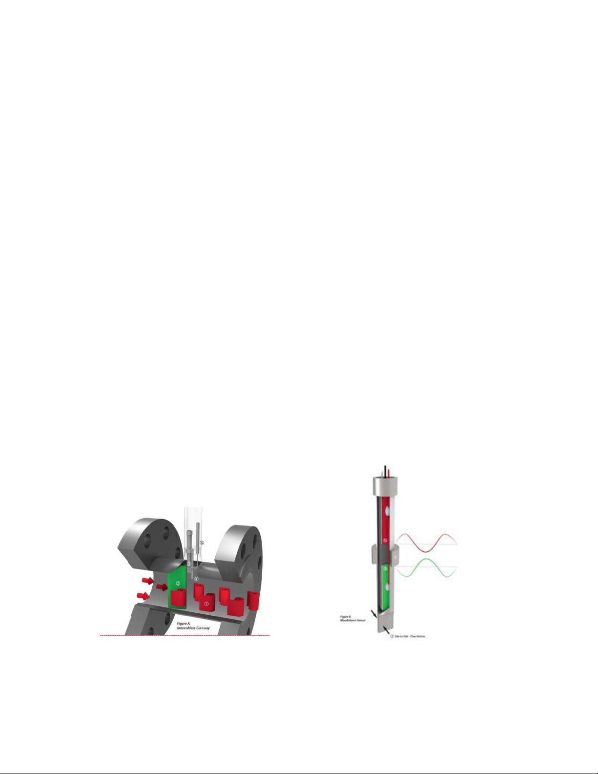
Figure A: InnovaMass Cutaway
8
Very similar to the way a tree branch in a fast-flowing stream creates swirls or vortices in the
downstream flow, Figure A shows the alternating vortices (1) shed by the bluff body (2) inside
every InnovaMass. These vortices flex the instrument piezoelectric sensor tab (3), producing a
frequency output that is directly proportional to the flow rate.
Multivariable mass flow is achieved when a temperature sensor (4) is immersed in the flow
stream to measure the temperature of the flowing gas, liquid or steam. Simultaneously, a pressure
sensing port (5) leads up to an isolated pressure transducer.
MassBalance™ Sensor
Figure B takes a close-up view of (3) in Figure A above. This cutaway view of the sensor features
our patented MassBalance technology which works mechanically with DSP (Digital Signal
Processing) to cancel out external vibration influences. The MassBalance sensor has two sensing
beams (1 a & 1 b) isolated from each other by a mechanical ground (2). A piezoelectric crystal is
mounted inside the vortex-sensing beam (1 b) in a cantilevered (fixed at one end) fashion in the
flow path for sensing vortices shed from the bluff body. A second piezoelectric crystal is mounted
in a vibration-sensing beam (1 a), for sensing external vibrations only, extending in a cantilevered
fashion away from the vortex-sensing beam. The vortices formed by the flow around the shedder
bar push the sensor tab (3) “side-to-side,” flexing the piezoelectric crystals and causing them to
generate a voltage pulse with a frequency proportional to the flow rate.
The entire assembly is affected by vibration. Vibration affects sensor 1 a and 1 b equally, so the
two sets of piezoelectric crystals are configured to cancel out the vibration signal while only
sensor 1 b feels the “side-to-side” flow signal.
The waveforms above illustrate the vibration signals from the two opposing sensing beams inside
the MassBalance sensor. They are designed to be 180° out of phase from each other and when
added together effectively eliminate the vibration component. The sensor is mechanically
balanced and provides a very clean flow velocity signal where it undergoes advanced digital
signal processing. This clean velocity signal leads to enhanced noise and vibration rejection,
allowing measurement sensitivity at low flows.
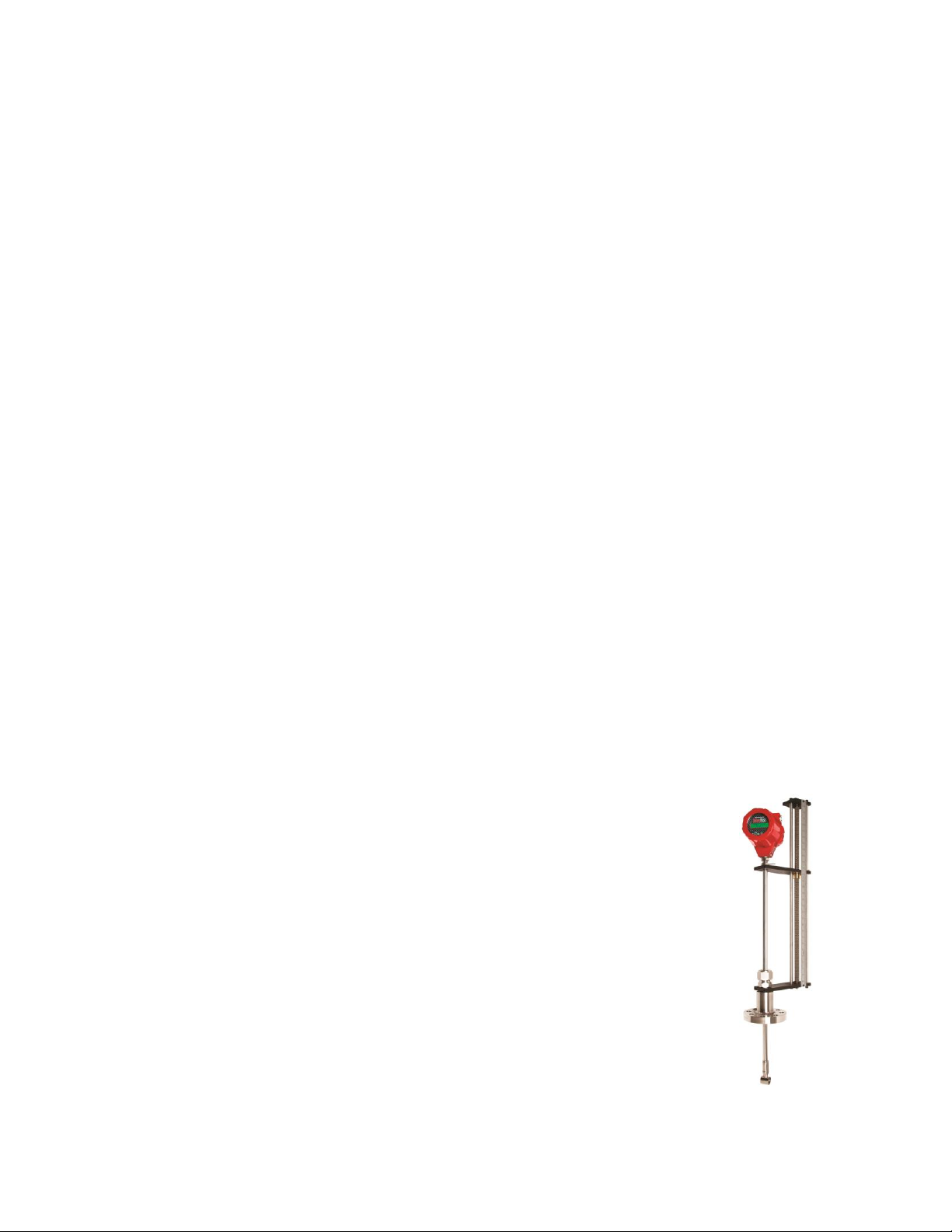
The Flexibility of Insertion
The 241i insertion vortex meter is an economical solution for applications from 2inch (50.8mm) pipes to 72 inches (1.8 M) in diameter and larger. Volumetric or
multivariable measurement is possible with a single pipe insertion point, greatly
reducing installation costs (Figure B). The 241i can be hot tapped into applications
with an optional probe retractor (shown right). More compact probe lengths are
available based on application requirements.
Raptor II OS Enhances Accuracy with FloPro™
Driven by Raptor II OS, the 241i insertion has a vastly improved flow profile
calculation using a proprietary application called FloPro. With all insertion point
velocity flow meters, knowing the flow profile inside the pipe or duct is key to stable
and reliable accuracy. Traditional insertion meters use a simple formula from Miller
that calculates flow profile assuming turbulent flow only.
FloPro makes no assumptions. It applies a sophisticated mathematical calculation for higher
resolution and understanding of flow profile. In addition to turbulent flow, FloPro calculates
9
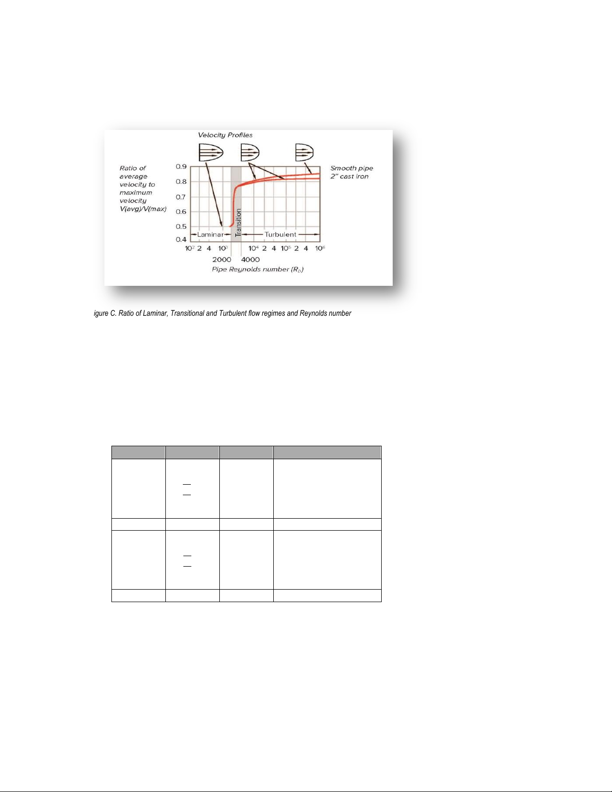
laminar and transitional flow in real-time as they would occur inside the pipe or duct (See Figure
Gas
Liquid
Vmin
√
25
⍴
𝑓𝑡/𝑠
1 ft/s
English (lb/ft3)
Vmax
300 ft/s
30 ft/s
Vmin
√
37
⍴
𝑚/𝑠
0.3 m/s
Metric (kg/m3)
Vmax
91 m/s
9.1 m/s
C). This results in increased accuracy, particularly at low flow rates of Reynolds Number of 5000
and below.
Figure C. Ratio of Laminar, Transitional and Turbulent flow regimes and Reynolds number
(Source: Richard Miller, Flow Measurement Engineering Handbook.)
Flow Velocity Range
To ensure trouble-free operation, vortex flow meters must be correctly sized so that the flow
velocity range through the meter lies within the measurable velocity range (with acceptable
pressure drop) and the linear range.
The measurable range is defined by the minimum and maximum velocity using the following
table.
Figure D. Flow Velocity Range
The pressure drop for series 241i insertion meters is negligible. The pressure drop for 240i Series
inline meters is defined as:
P = .00024 V
P = .000011 V
2
English units (P in psi, in lb/ft3, V in ft/sec)
2
Metric units (P in bar, in kg/m3, V in m/sec)
10

Re =
V D
St =
f d
V
The linear range is defined by the Reynolds number. The Reynolds number is the ratio of
the inertial forces to the viscous forces in a flowing fluid and is defined as:
Where
Re = Reynolds Number
= mass density of the fluid being measured
V = velocity of the fluid being measured
D = internal diameter of the flow channel
= viscosity of the fluid being measured
The Strouhal number is the other dimensionless number that quantifies the vortex phenomenon.
The Strouhal number is defined as:
Where
St = Strouhal Number
f = frequency of vortex shedding
d = shedder bar width
V = fluid velocity
InnovaMass meters exhibit a constant Strouhal number across a large range of Reynolds numbers,
indicating a consistent linear output over a wide range of flows and fluid types. Below this linear
range, the intelligent electronics in InnovaMass automatically corrects for the variation in the
Strouhal number with the Reynolds number. The meter’s smart electronics corrects for this nonlinearity via its simultaneous measurements of the process fluid temperature and pressure. This
data is then used to calculate the Reynolds number in real time.
Temperature Measurement
InnovaMass flow meters use a 1000 ohm platinum resistance temperature detector (PRTD) to
measure fluid temperature.
Pressure Measurement
InnovaMass flow meters incorporate a solid-state pressure transducer isolated by a 316 stainless
steel diaphragm. Digital compensation allows these transducers to operate within a 0.5% of full
scale accuracy band within the entire ambient temperature range of -40°F to 140°F (-40 to 60°C).
Thermal isolation of the pressure transducer ensures the same accuracy across the allowable
process fluid temperature range of -40°F to 392°F (-40 to 200°C).
Flow Meter Configurations
InnovaMass Vortex Mass Flow Meters are available in two model configurations:
• 240i Series inline flow meter (replaces a section of the pipeline)
• 241i Series insertion flow meter (requires a compression fitting, packing gland, or probe
retractor to “cold” tap or a “hot” tap into an existing pipeline)
11

Both the inline and insertion configurations are similar in that they both use identical electronics
and have similar sensor heads. Besides installation differences, the main difference between an
inline flow meter and an insertion flow meter is their method of measurement.
For an inline vortex flow meter, the shedder bar is located across the entire diameter of the flow
body. Thus, the entire pipeline flow is included in the vortex formation and measurement. The
sensing head, which directly measures velocity, temperature and pressure is located just
downstream of the shedder bar.
Insertion vortex flow meters have a shedder bar located across the diameter of a short tube. The
velocity, temperature and pressure sensor are located within this tube just downstream of a builtin shedder bar. This entire assembly is called the insertion sensing head. It fits through any entry
port with a 1.875 inch minimum internal diameter.
The sensing head of an insertion vortex flow meter directly monitors the velocity at a point in the
cross-sectional area of a pipe, duct, or stack (referred to as “channels”). The velocity at a point in
the pipe varies as a function of the Reynolds number. The insertion vortex flow meter computes
the Reynolds number and then computes the total flow rate in the channel. The output signal of
insertion meters is the total flow rate in the channel. The accuracy of the total flow rate
computation depends on adherence to the piping installation requirements given in Chapter 2. If
adherence to those guidelines cannot be met, contact the factory for specific installation advice
Multivariable Options
The 240i or 241i models are available with the following options: V, volumetric flow meter; VT,
velocity and temperature sensors; VTP, velocity, temperature, and pressure sensors.
Line Size/Process Connections/Materials
The 240i Inline model is built for line sizes 1 through 8-inch flanged design using ANSI 150, 300,
600 or DN PN 16, 40, or 64 class flanges.
The 241i insertion model can be used in line sizes 2 inch and greater and is built with a
compression fitting or packing gland design using 2-inch NPT, or 2-inch flanged connections
(ANSI 150, 300, 600 or DN PN16, 40, or 64 class flanges). The packing gland design can be
ordered with a retractor.
InnovaMass flow meter electronics are available mounted directly to the flow body, or remotely
mounted. The electronics housing may be used indoors or outdoors, including wet environments.
Available input power options are DC or AC powered. Three analog output signals are available
for flow rate, temperature, and pressure. An alarm relay output, a pulse output signal for remote
totalization and RS-232, USB, Modbus, HART, Profibus DP, and Foundation Fieldbus
communications are also available.
InnovaMass flow meters include a local 2 x 16 character LCD display housed within the
enclosure. Local operation and reconfiguration is accomplished using six pushbuttons operated
via finger touch. The electronics include nonvolatile memory that stores all configuration
information. The nonvolatile memory allows the flow meter to function immediately upon power
up, or after an interruption in power. All flow meters are calibrated and configured for the
customer’s flow application.
12

Consult the flow meter nameplate for specific flow meter approvals before
any hazardous location installation.
Chapter 2: Installation
Installation Overview
Sierra’s InnovaMass Vortex Flow Meter installations are simple and straightforward. Both the
240i Inline and 241i Insertion type flow meter installations are covered in this chapter. After
reviewing the installation requirements given below, see page 14 for 240i installation instructions.
See page 16 for 241i installation instructions. Wiring instructions begin on page 23.
Flow Meter Installation Requirements
Before installing the flow meter, verify the installation site allows for these considerations:
1. Line pressure and temperature will not exceed the flow meter rating.
2. The location meets the required minimum number of pipe diameters upstream and
downstream of the sensor head as illustrated in Figure 1, page 14.
3. Safe and convenient access with adequate overhead clearance for maintenance purposes.
4. Verify that the cable entry into the instrument meets the specific standard required for
hazardous area installations. The cable entry device shall be of a certified flameproof
type, suitable for the conditions of use and correctly installed. The degree of protection
of at least IP66 to EN 60529 is only achieved if certified cable entries are used that are
suitable for the application and correctly installed. Unused apertures shall be closed with
suitable blanking elements.
5. For remote installations, verify the supplied cable length is sufficient to connect the flow
meter sensor to the remote electronics.
Also, before installation check your flow system for anomalies such as:
leaks
valves or restrictions in the flow path that could create disturbances in the flow profile
that might cause unexpected flow rate indications
Unobstructed Flow Requirements
Select an installation site that will minimize possible distortion in the flow profile. Valves,
elbows, control valves and other piping components may cause flow disturbances. Check your
specific piping condition against the examples shown below. In order to achieve accurate and
repeatable performance install the flow meter using the recommended number of straight run pipe
diameters upstream and downstream of the sensor.
Note: For liquid applications in vertical pipes, avoid installing with flow in the downward
direction because the pipe may not be full at all points. Choose to install the meter with flow in
the upward direction if possible.
13
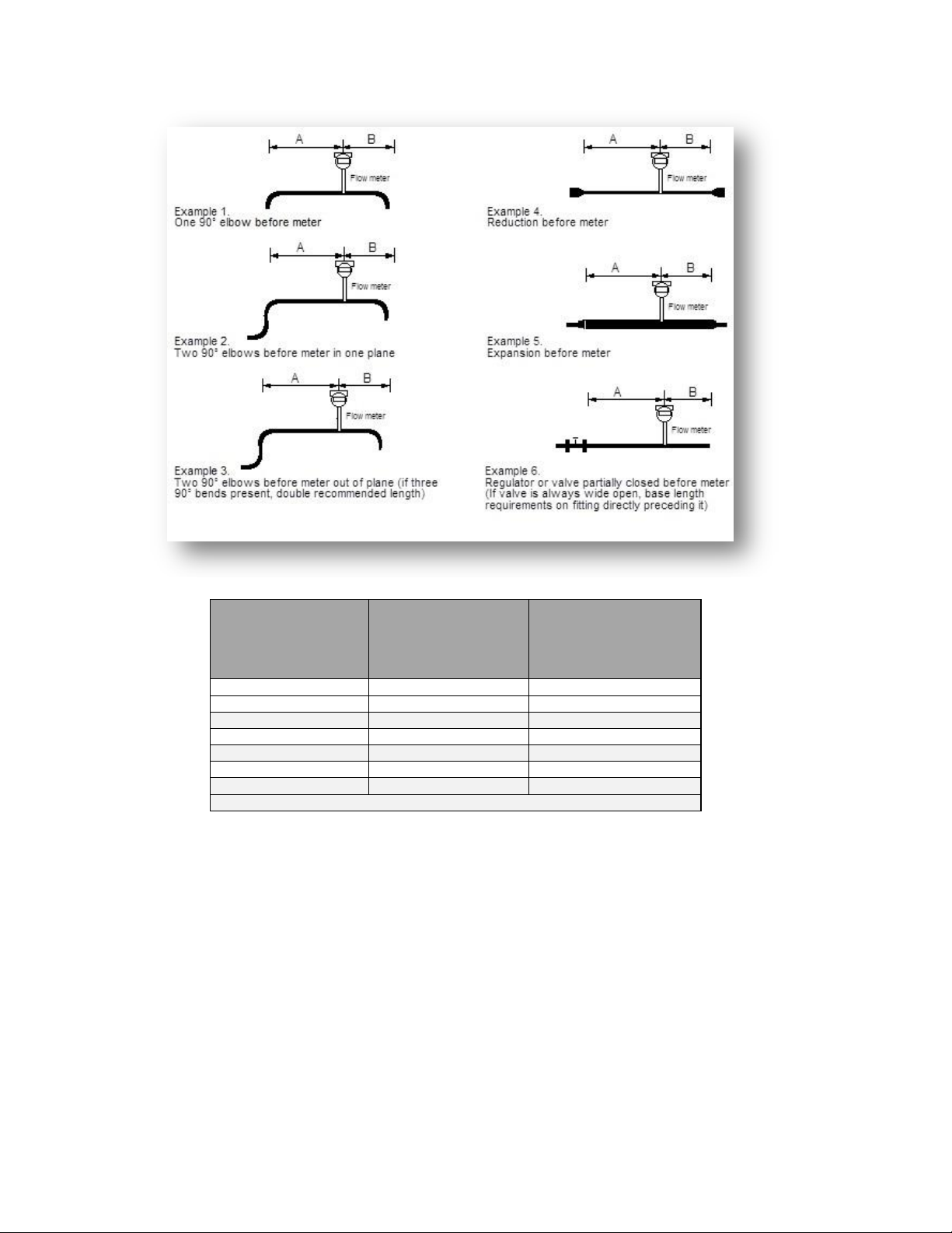
Minimum Required
Upstream
Diameters
Minimum Required
Downstream Diameters
Example A B
1
10 D
5 D
2
15 D
5 D 3 25 D
10 D
4
10 D
5 D 5 20 D
5 D 6 25 D
10 D
D=Internal diameter of channel. N/A=Not applicable
240i Inline Flow Meter Installation
Unless otherwise noted on the application datasheet (ADS), the meter inside diameter is equal to
the same size nominal pipe ID in schedule 80. For example, a 2-inch meter has an ID of 1.939
inches (2 inch schedule 80). Do not install the meter in a pipe with an inside diameter
smaller than the inside diameter of the meter. For schedule 160 and higher pipe, a special
meter is required. Consult the factory before purchasing the meter.
The InnovaMass 240i meters require customer-supplied gaskets. When selecting gasket material
make sure that it is compatible with the process fluid and pressure ratings of the specific
installation. Verify that the inside diameter of the gasket is larger than the inside diameter of the
flow meter and adjacent piping. If the gasket material extends into the flow stream, it will disturb
the flow and cause inaccurate measurements.
Figure 1: Recommended Pipe Length Requirements for Installation, 240i/241i Series
14
Vortex flow meters are not suitable for two-phase flows (i.e., liquid and gas
mixtures). For horizontal pipelines having a process temperature above 300°
F (149°C), mount the meter at a 45 or 90-degree angle to avoid overheating
the electronics enclosure.
When using toxic or corrosive gases, purge the line with inert gas for a
minimum of four hours at full gas flow before installing the flow meter.
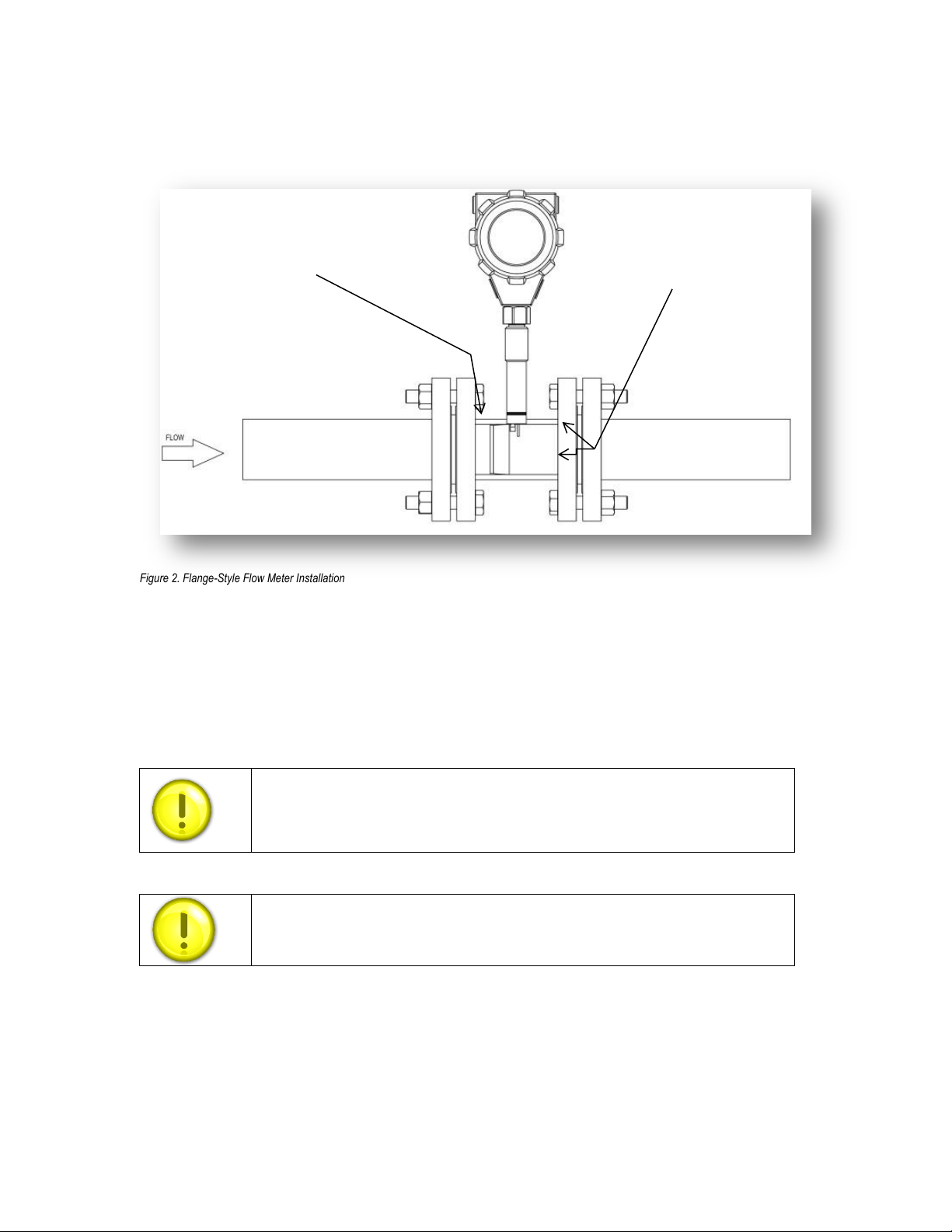
Shedder bar (bluff
body) is positioned
upstream of the
sensor
Note: Do not allow
any gasket
material to extend
into the flow profile
Figure 2. Flange-Style Flow Meter Installation
Flange-Style Flow Meter Installation
Install the flange-style meter between two conventional pipe flanges of the same nominal size as
the flow meter. If the process fluid is a liquid, make sure the meter is located where the pipe is
always full. This may require locating the meter at a low point in the piping system.
When installing the meter make sure the body marked with a flow arrow is positioned with the arrow
head pointing in the direction of flow. Installing the meter opposite this direction will result in
completely inaccurate flow measurement. To install the meter:
1. Turn off the flow of process gas, liquid or steam. Verify that the line is not pressurized.
Confirm that the installation site meets the required minimum upstream and downstream
pipe diameters.
15
1
2
34
1
2
34
5
6
7
8
1
5
9
3
7
11
2
6
10
4
8
12
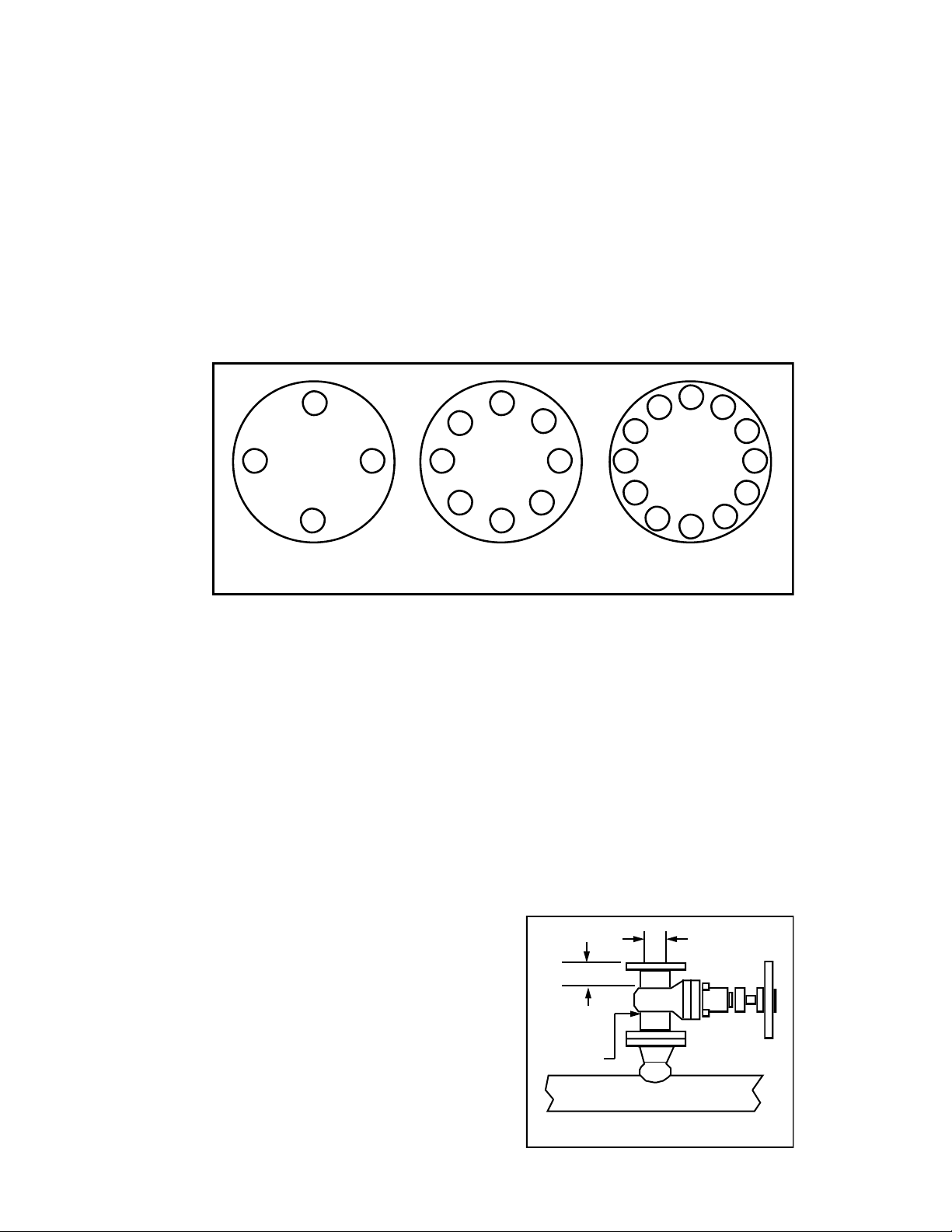
4-bolt 8-bolt 12-bolt
1.875-inch min.
valve bore
2-inch min.
2-inch
valve size
Isolation Valve Requirements
2. Seat the meter level and square on the mating connections with the flow arrow on the
upstream side, with the arrow head pointing in the direction of flow. Position a gasket in
place for each side. Make sure both gaskets are smooth and even with no gasket material
extending into the flow profile. Obstructions in the pipeline will disturb the flow and cause
inaccurate measurements.
3. Install bolts in both process connections. Tighten the nuts in the sequence shown in the
image below. Check for leaks after tightening the flange bolts. The required bolt load for
sealing the gasket joint is affected by several application-dependent factors, therefore the
required torque for each application may be different. Refer to the ASME Pressure Vessel
Code guidelines for bolt tightening standards.
241i Insertion Flow Meter Installation
Prepare the pipeline for installation using either a cold tap or hot tap method described on the
following pages. Refer to a standard code for all pipe tapping operations. The following tapping
instructions are general in nature and intended for guideline purposes only. Before installing the
meter, review the mounting position and isolation value requirements given below.
Mounting Position
Allow clearance between the electronics enclosure top and any other obstruction when the meter
is fully retracted.
Isolation Valve Selection
An isolation valve may be used with 241i meters.
It must meet the following requirements:
1. A minimum valve bore diameter of 1.875
inches is required, and the valve’s body size
should be two inches. Normally, gate valves
are used.
2. Verify that the valve’s body and flange rating
are within the flow meter’s maximum
operating pressure and temperature.
3. Choose an isolation valve with at least two
inches existing between the flange face and
16
the gate portion of the valve. This ensures that the flow meter’s sensor head will not
When using toxic or corrosive gases, purge the line with inert gas for a
minimum of four hours at full gas flow before installing the flow meter.
All flow meter connections, isolation valves and fittings for cold tapping
must have the same or higher pressure and temperature rating as the main
pipeline.
interfere with the operation of the isolation valve.
Cold Tap Guidelines
Refer to a standard code for all pipe tapping operations. The following tapping instructions are
general in nature and intended for guideline purposes only.
1. Turn off the flow of process gas, liquid or steam. Verify that the line is not pressurized.
2. Confirm that the installation site meets the minimum upstream and downstream pipe
diameter requirements. See Figure 1, page 14.
3. Use a cutting torch or sharp cutting tool to tap into the pipe. The pipe opening must be at
least 1.875 inches in diameter. (Do not attempt to insert the sensor probe through a
smaller hole.
4. Remove all burrs from the tap. Rough edges may cause flow profile distortions that could
affect flow meter accuracy. Also, obstructions could damage the sensor assembly when
inserting into the pipe.
5. After cutting, measure the thickness of the cut-out and record this number for calculating
the insertion depth.
6. Weld the flow meter pipe connection on the pipe. Make sure this connection is within
± 5° perpendicular to the pipe centerline.
7. Install the isolation valve (if used).
8. When welding is complete and all
fittings are installed, close the isolation
valve or cap the line. Run a static
pressure check on the welds. If pressure
loss or leaks are detected, repair the joint
and re-test.
9. Connect the meter to the pipe process
connection.
10. Calculate the sensor probe insertion depth and insert the sensor probe into the pipe
as described on the following pages.
17

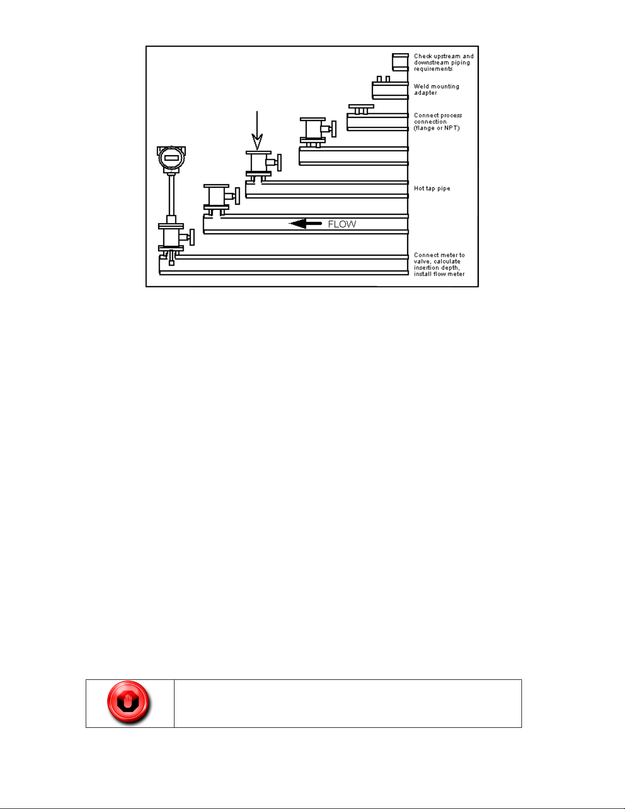
Hot Tap Guidelines
Hot tapping must be performed by a trained professional. U.S. regulations
often require a hot tap permit. The manufacturer of the hot tap equipment
and/or the contractor performing the hot tap is responsible for providing
proof of such a permit.
All flow meter connections, isolation valves, and fittings for hot tapping
must have the same or higher pressure and temperature rating as the main
pipeline.
Refer to a standard code for all pipe tapping operations. The following tapping
instructions are general in nature and intended for guideline purposes only.
1. Confirm that the installation site meets the minimum upstream and downstream pipe
diameter requirements.
2. Weld a two inch-inch mounting adapter on the pipe. Make sure the mounting adapter
is within ± 5° perpendicular to the pipe centerline (See previous page under
“Isolation Valve Selection”). The pipe opening must be at least 1.875 inches in
diameter.
3. Connect a two inch process connection on the mounting adapter.
4. Connect an isolation valve on the process connection. The valve’s full open bore
must be at least 1.875 inches in diameter.
5. Run a static pressure check on the welds. If pressure loss or leaks are detected, repair
the joint and re-test.
6. Connect the hot tapping equipment to the isolation valve, open the isolation valve and
drill at least a 1.875 inch diameter hole.
7. Retract the drill, close the isolation valve, and remove the hot tapping equipment.
8. Connect the flow meter to the isolation valve and open the isolation valve.
9. Calculate the sensor probe insertion depth and insert the sensor probe into the pipe as
described pages 17-19.
18
Connect isolation
valve and test for
leaks
xxxxxxxxxxxxxxxxxxxx
xxxxxxxxxxxxxxxxxxxx
xxxxxxxxxxxxxxxxxxxx
xxxxxxxxxxxxxxxxxxxx
Purge pipe
Figure 4. Hot Tap Sequence
An insertion tool must be used for any installation where a flow meter is
inserted under pressure greater than 50 psig.
Flow Meter Insertion
The sensor head must be properly positioned in the pipe. For this reason, it is important that
insertion length calculations are carefully followed. A sensor probe inserted at the wrong depth in
the pipe will result in inaccurate readings.
Insertion flow meters are applicable to pipes 2-inches and larger. For pipe sizes ten inches and
smaller, the centerline of the meter’s sensing head is located at the pipe’s centerline. For pipe sizes
larger than ten inches, the centerline of the sensing head is located in the pipe’s cross section five
inches from the inner wall of the pipe; i.e., its “wetted” depth from the wall to the centerline of the
sensing head is five inches.
Standard Probe length, S, of the stem is 33.5 inches (850.9 mm).
Compact Probe length is 16.5 inches (419.1 mm).
Use the Correct Insertion Formula
Depending on your flow meter’s process connection, use the applicable insertion length formula
and installation procedure as follows:
Flow meters with a compression type connection (NPT or flanged) follow the instructions
beginning on page 19.
Flow meters with a packing gland type connection (NPT or flanged) follow the instructions
beginning on page 21.
19
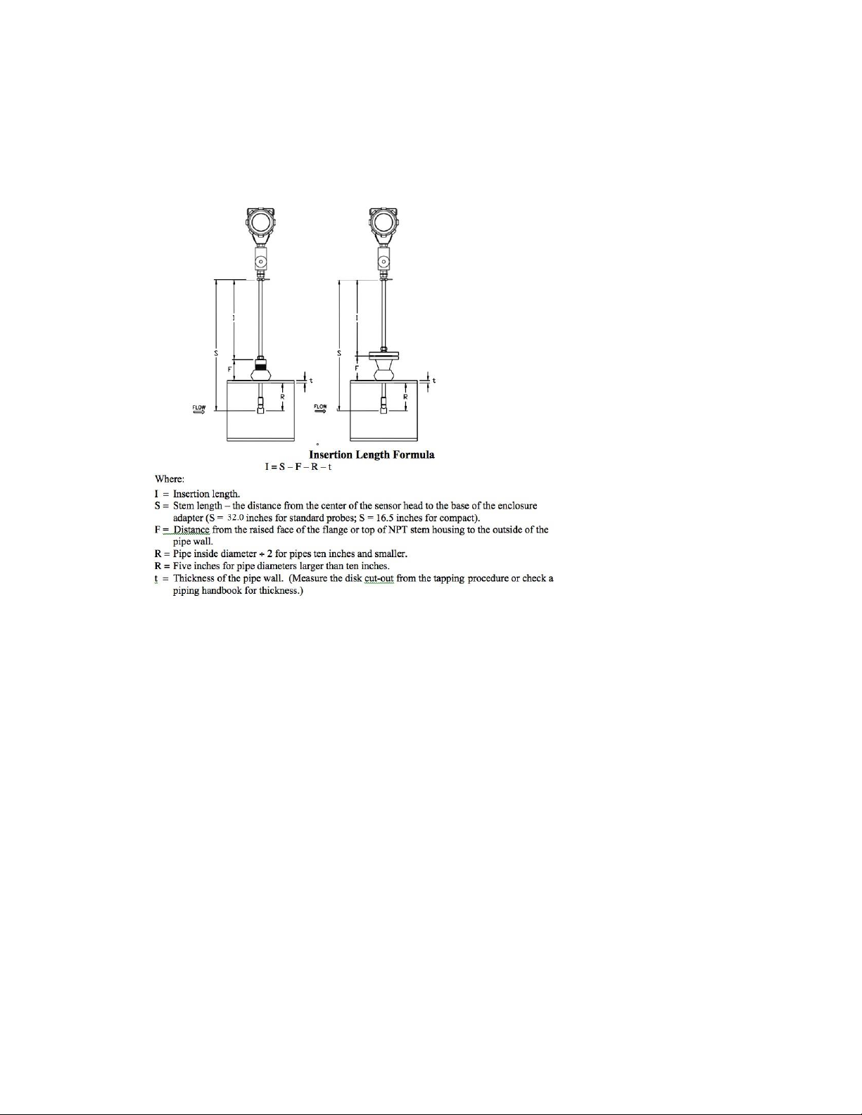
Installing Flow Meters with a Compression Connection
Use the following formula to determine insertion length for flow meters (NPT and flanged) with a
compression process connection. The installation procedure is given on the next page.
Figure 5. Insertion Calculation (Compression Type)
Example:
To install a 241i meter with a standard probe (S = 32.0 inches) into a 14-inch schedule 40 pipe, the
following measurements are taken:
F=3 inches
R=5 inches
t=0.438 inches
The insertion length for this example is 23.56 inches. Insert the stem through the fitting until an
insertion length of 23.56 inches is measured with a ruler.
20
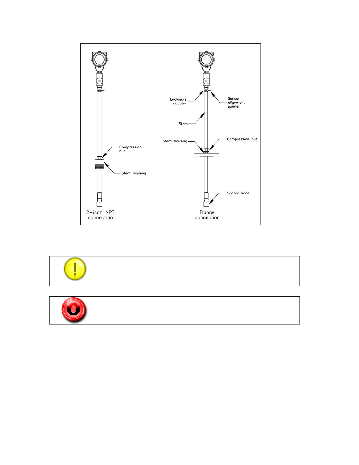
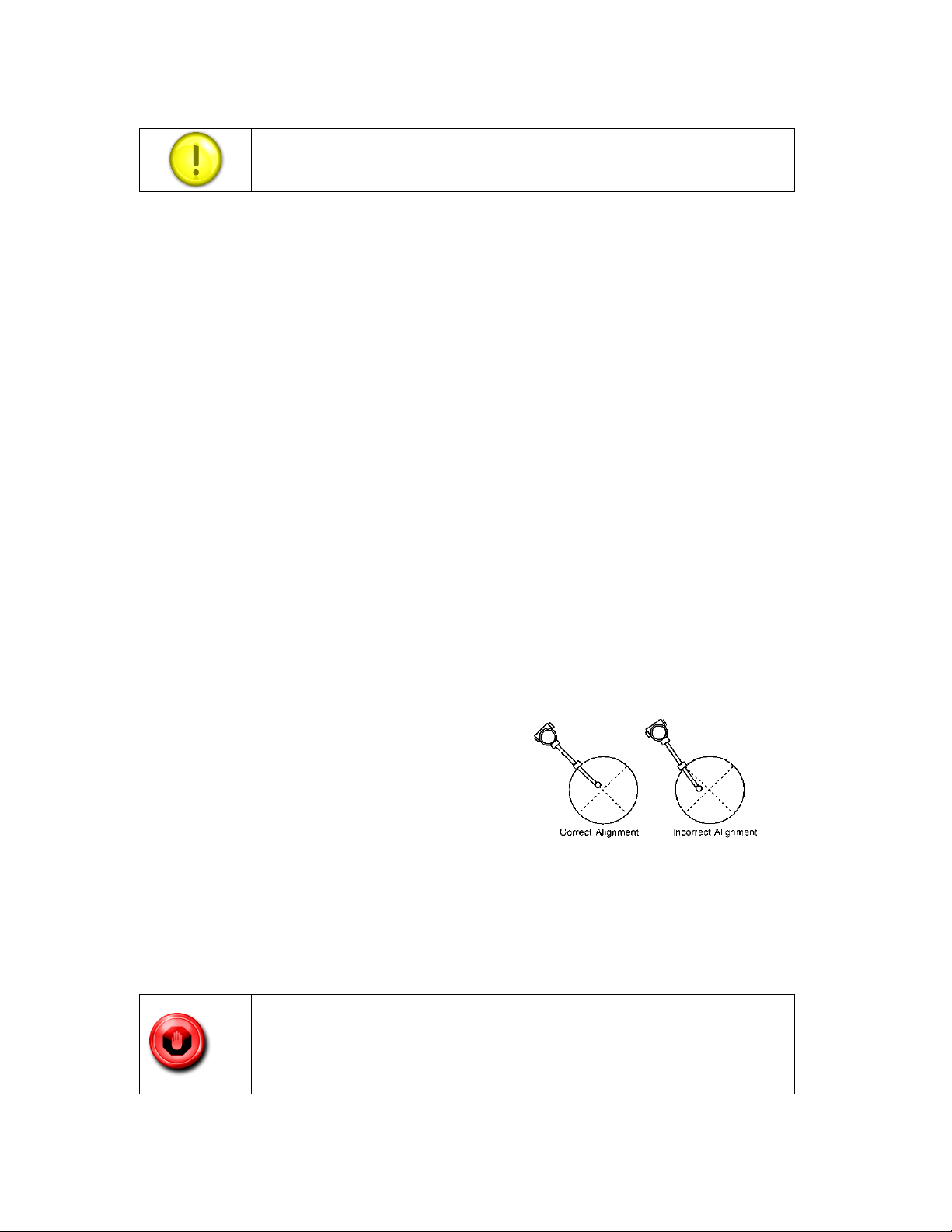
Insertion Procedure for Meters with a Compression Connection
The sensor alignment pointer must point downstream, in the direction of
flow.
To avoid serious injury, DO NOT loosen the compression fitting under
pressure.
Figure 6. Insertion Flow Meter with Compression Type Fitting
1. Calculate the required sensor probe insertion length.
2. Fully retract the stem until the sensor head is touching the bottom of the stem
housing. Slightly tighten the compression nut to prevent slippage.
3. Bolt or screw the flow meter assembly into the process connection. Use Teflon tape or
pipe sealant to improve the seal and prevent seizing on NPT styles.
4. Hold the meter securely while loosening the compression fitting. Insert the sensor
into the pipe until the calculated insertion length, I, is measured between the base of
the enclosure adapter and the top of the stem housing, or to the raised face of the
flanged version. Do not force the stem into the pipe.
21
5. Align the sensor head using the sensor alignment pointer. Adjust the alignment pointer
parallel to the pipe and pointing downstream.
6. Tighten the compression fitting to lock the stem in position. When the compression
fitting is tightened, the position is permanent.
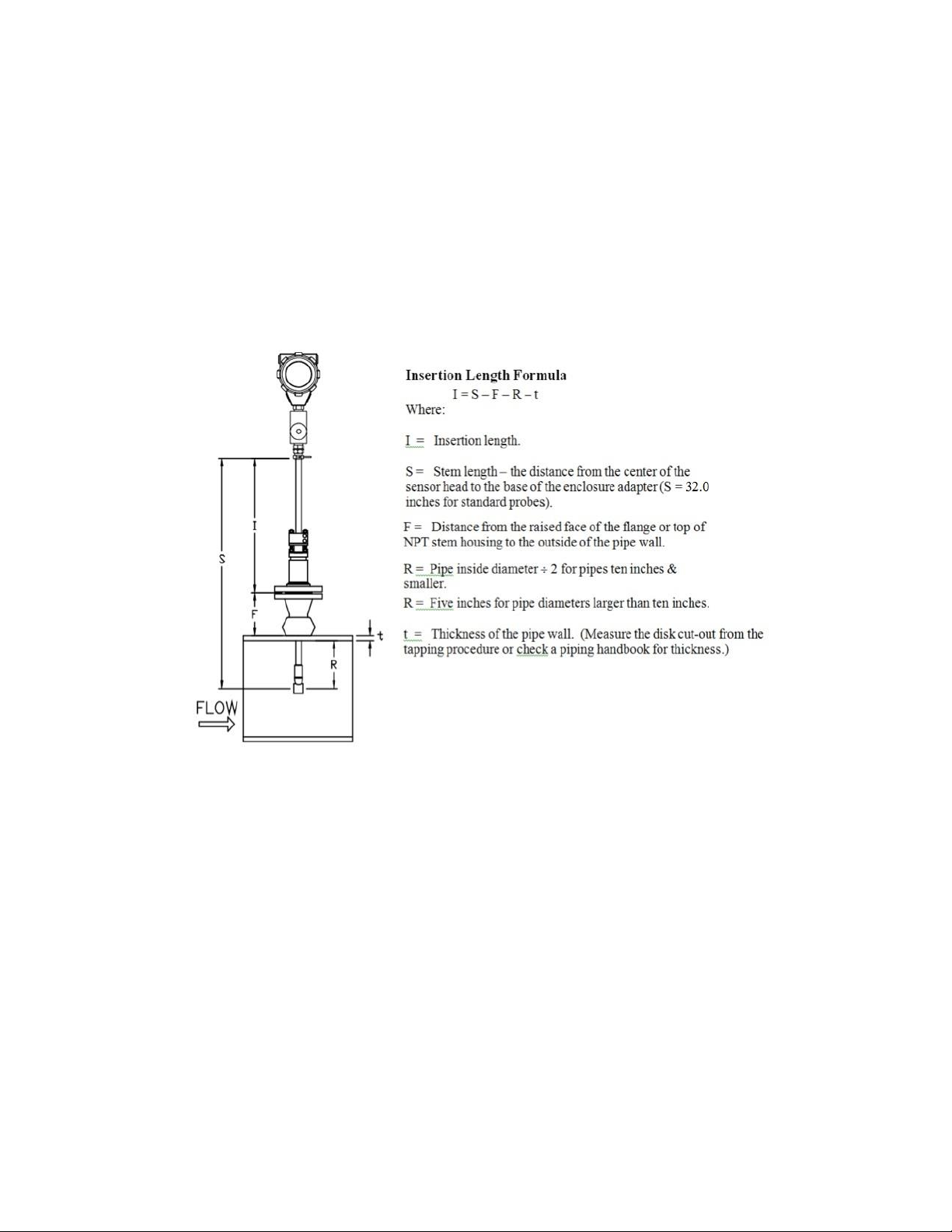
Installation of Meters with Packing Gland Connection
Use the following formula to determine insertion depth for meters with a packing gland connection (NPT
and flanged)
Figure 7. Insertion Calculation
Example:
To install a 241i Flow Meter with a standard probe (S = 32.0) into a 14-inch schedule 40 pipe, the
following measurements are taken:
F = 3 inches
R = 5 inches
t = 0.438 inches
The example insertion length is 23.56 inches.
22
Insertion Procedure for Flow Meters (Packing Gland Connection)
Failure to adhere to these guidelines may result in water damage that is
not covered under Sierra’s Warranty Policy.
The line pressure must be less than 50 psig for installation.
The sensor alignment pointer must point downstream, in the direction of
the flow.
1. Calculate the required sensor probe insertion length.
2. Fully retract the stem until the sensor head is touching the bottom of the stem housing.
Remove the two top stem clamp nuts and loosen two stem clamp bolts. Slide the stem
clamp away to expose the packing gland nuts. Loosen the two packing gland nuts.
3. Align the sensor head using the sensor alignment pointer. Adjust the alignment
pointer parallel to the pipe and pointing downstream.
4. Insert the sensor head into the pipe until insertion length, I, is achieved. Do not force
the stem into the pipe.
5. Tighten the packing gland nuts to stop leakage around the stem. Do not torque over
20 ft-lbs.
6. Slide the stem clamp back into position. Torque stem clamp bolts to 15 ft-lbs.
Replace the stem clamp nuts and torque to 10-15 ft-lbs.
Wiring Connections-Protection of Your Meter
To protect your investment and be certain of a long reliable service life, we have compiled some
guidelines (from experience) that will aid your installation team in properly protecting the
electronics from the application environment. These instruments have been designed for and
proven reliable in some of the most extreme process conditions in industry: Mining, Oil and Gas,
Water, Wastewater etc. The key however is to follow best practices to insure a proper seal to
protect the internal components of this precision instrument.
Water penetration can lead to a damaged flow meter. Sierra’s "E" HALE ex-proof enclosures are
rated to a NEMA4X, IP66 rating. This provides protection against, rain, sleet, snow and
splashing water, but water can damage the sensor, electronics or wiring terminals if the meter is
not properly installed and maintained.
23

To minimize the potential for water damage, Sierra Instruments recommends the following:
Install conduit seals near the enclosures on all ports.
Use a cable gland design that provides shielded cable termination and an environmental
seal against dirt and water.
Do not bend, kink, or otherwise distort the cable at the entry points to the cable glands.
Route conduit or cable using a drip loop or drain as close as possible to the enclosure
ports unless the cable slopes directly down.
If the factory cable glands are replaced to install other adapter fittings, conduit fittings,
cable glands, or any other modification to the cable entry points be sure to use a good
quality thread sealant on all NPT threads as well as verifying they are all tightened and
sealed appropriately so as not to leak.
Be certain to use NPT threads when connecting to the housing. Some electrical fittings
are not tapered but will fit in the NPT ports of the enclosure. Sufficient Teflon tape and
pipe dope is recommended to insure a leak tight seal.
If you are uncertain of the conditions the interior of the housing is subjected to over time,
a small temporary datalogger can be placed in the housing to record temperature and
humidity to establish a baseline. Corrective action can be made based on this data before
instrument degradation sets in. Contact Sierra Instruments for suggested sources of small
dataloggers.
Keep the enclosure lids sealed tight using the supplied o-rings.
As part of the lid o-ring inspections look for any signs of condensation inside of the
enclosure. If condensation or signs of condensation/corrosion are found be sure all
fittings/seals are securely tightened as well as a desiccant bag can be used and replaced as
needed. This can be particularly important if the temperature is cycled.
24
Specific Wiring Related Requirements for Agency Approved cFMus and ATEX/IECEx
Wiring Entry
Wiring Entry
Certified Units
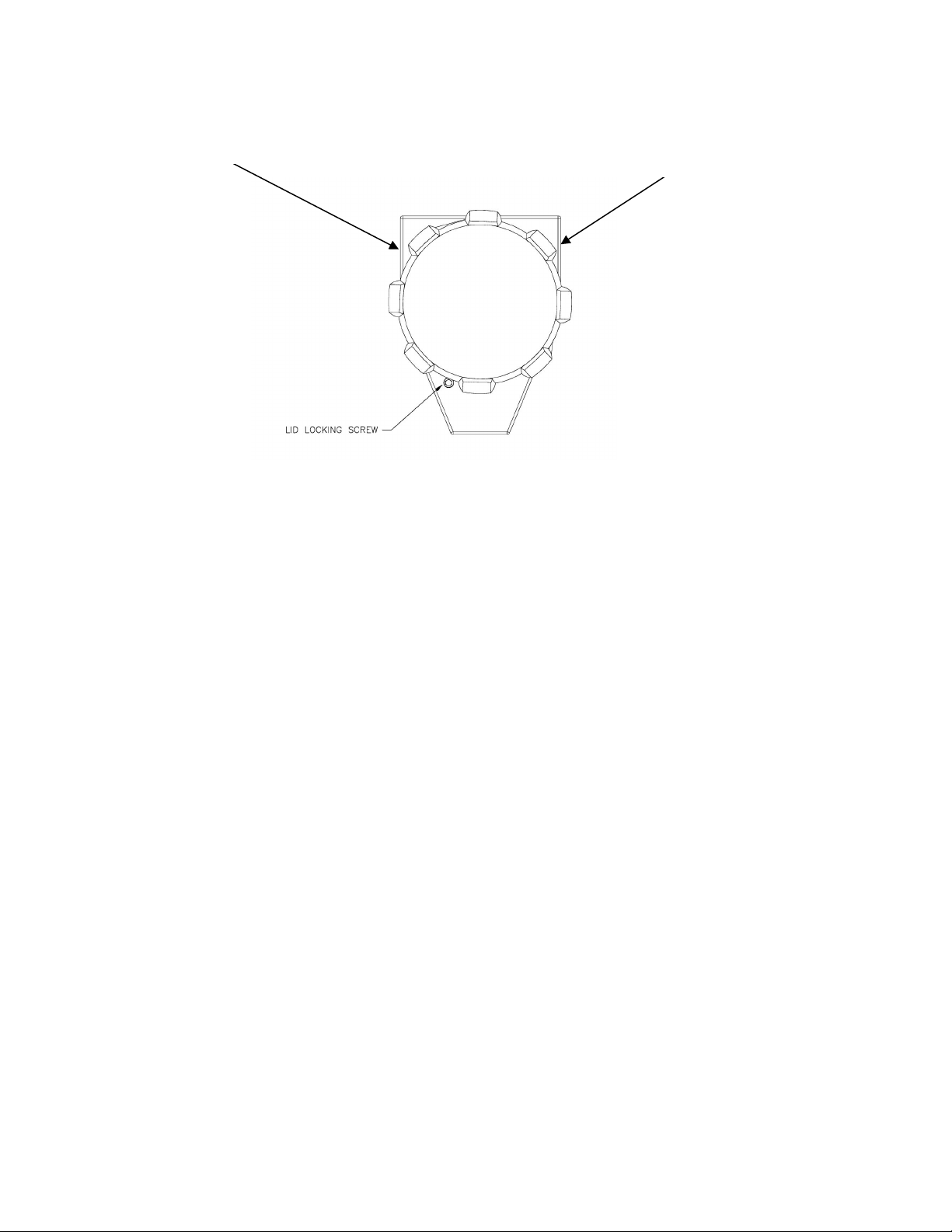
Figure 8. InnovaMass 240i and 241i Main and Remote Enclosure Shown with wiring entries
Shown above, the input power and signal wiring entry threads on the enclosures are ¾ inch -14
female NPT threads according to the NPT requirements of ANSI B1.20.1 plus +0.5 to +2.0 turns
deeper.
Unused entries are to be sealed with suitably certified plugs.
Field wiring should be rated 80°C (176°F) or above.
Flameproof/explosion proof joints should not be repaired, contact Sierra Instruments in
the event that repair of the joints is necessary.
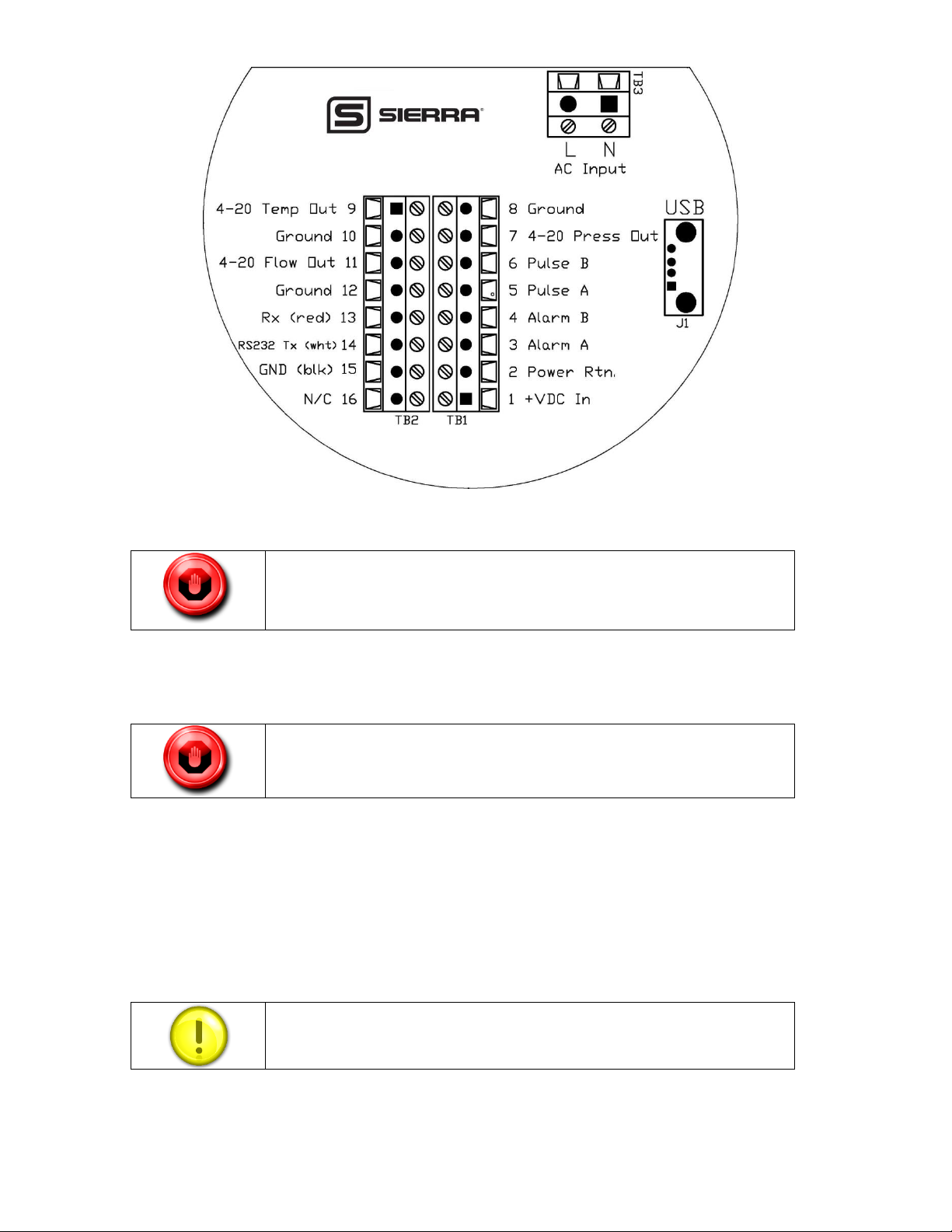
General Terminal Board Layout
Use the terminal blocks located inside the cap of the flow meter enclosure for all wiring
connections. Make sure to observe all CE compliance requirements for AC wiring connections
given on page 23. Note 4-20 mA outputs are configurable. Typically this will be flow,
temperature and pressure, as illustrated with Figure 9. All wiring procedures must be performed
with the power off and following good ESD practices.
25
To avoid potential electric shock, follow National Electric Code safety
practices or your local code when wiring this unit to a power source and to
peripheral devices. Failure to do so could result in injury or death. All AC
power connections must be in accordance with published CE directives.
Safety is guaranteed as long as the covers are correctly screwed and
locked.
Note: that this very minor adjustment, if necessary, does not affect the leak
integrity of the enclosure.
Figure 9. Wiring Access
Particular Recommendations: Lid Locking
The lid locking screws are #10-24 Socket Head Cap Screws (SHC Screw) that use a 5/32-inch
hex head wrench/driver to adjust (See Figure 10, page 24). To lock the lids, firmly tighten
down/secure the lid and then back out the associated SHC screw firmly so that the lid is secured
and locked in place.
If one of the ribs/bumps on the lid happens to line up so it is blocking access to the SHC screw,
then either slightly tighten the lid or loosen the lid slightly, just enough to gain access to the lid
locking SHC screw.
To un-lock the lid allowing for removal, just turn in the associated SHC screw so that it is no
longer in contact with the lid; then the lid can be removed. There are two lids to be locked on the
26
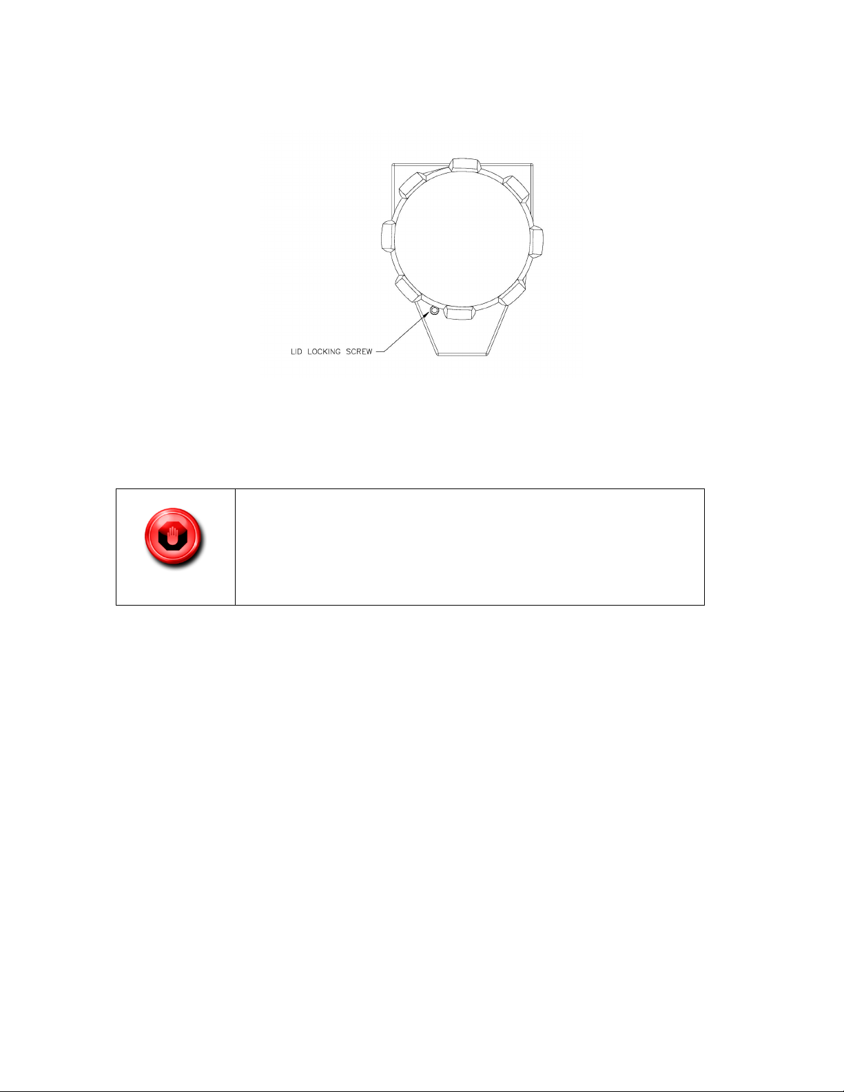
main enclosure and two lids to be locked on the remote enclosure (if E4 feature was ordered)
DO NOT OPEN WHEN AN EXPLOSIVE ATMOSPHERE IS
PRESENT
DO NOT OPEN WHEN ENERGIZED
POTENTIAL ELECTROSTATIC CHARGING HAZARD—SEE
INSTRUCTIONS
Figure 10. InnovaMass Main and Remote Enclosure Shown With Lid Locking Screw
enclosures in order to maintain the safety ratings.
The following warnings should be obeyed:
To minimize an electrostatic charging hazard on the exterior of the enclosures both the main and
remote (if E4 option ordered) enclosures should be connected to earth ground, see below for more
details.
1. Earthing: The Sierra Instruments units must be connected to a good quality earth. The
units are provided with internal and external earthing terminals.
2. External Earthing: The external earthing connections are located on the boss on the
outside of both the main housing and remote housing (E4 option if ordered) and consist
of an 18-8SS pan head Phillips screw (10-24 UNC-2B thread) and a serrated tooth #10
ring terminal for 16-14 AWG wire.
3. Internal Earthing: The internal earthing connection is located in the main and remote
(E4 option if ordered) housing terminal side and consist of an 18-8SS pan head Phillips
screw (10-24 UNC-2B thread) and a serrated tooth #10 ring terminal for 16-14 AWG
wire.
27
Input Power Wiring
All wiring procedures must be performed with the power Off.
The AC wire insulation temperature rating must meet or exceed 80 °C
(176°F).
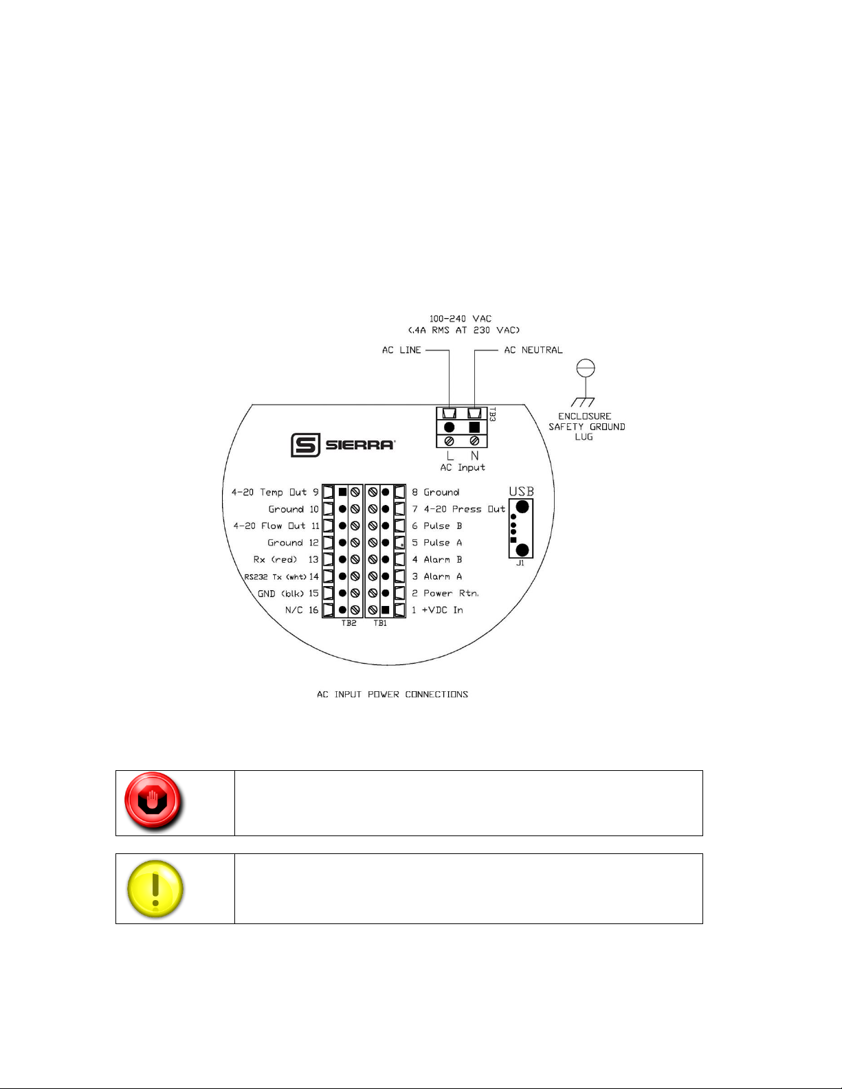
AC Power Wiring
The AC power wire size must be 26 to 16 AWG with the wire stripped 1/4 inch (6 mm).
Connect 100 to 240 VAC (0.2 Amps RMS at 230 VAC) to the neutral and line terminals
on the terminal block. Connect the ground wire to the safety ground lug. Torque all
connections to 4.43 to 5.31 in-lbs (0.5 to 0.6 Nm).
The Hazardous-Area enclosure has two separate conduit entries to maintain separation
between AC input power and output signal wiring. To eliminate the possibility of
noise interference, use a separate cable entry for the AC power and signal lines. See
Figure 11.
Figure 11: AC Input Power Connections
28
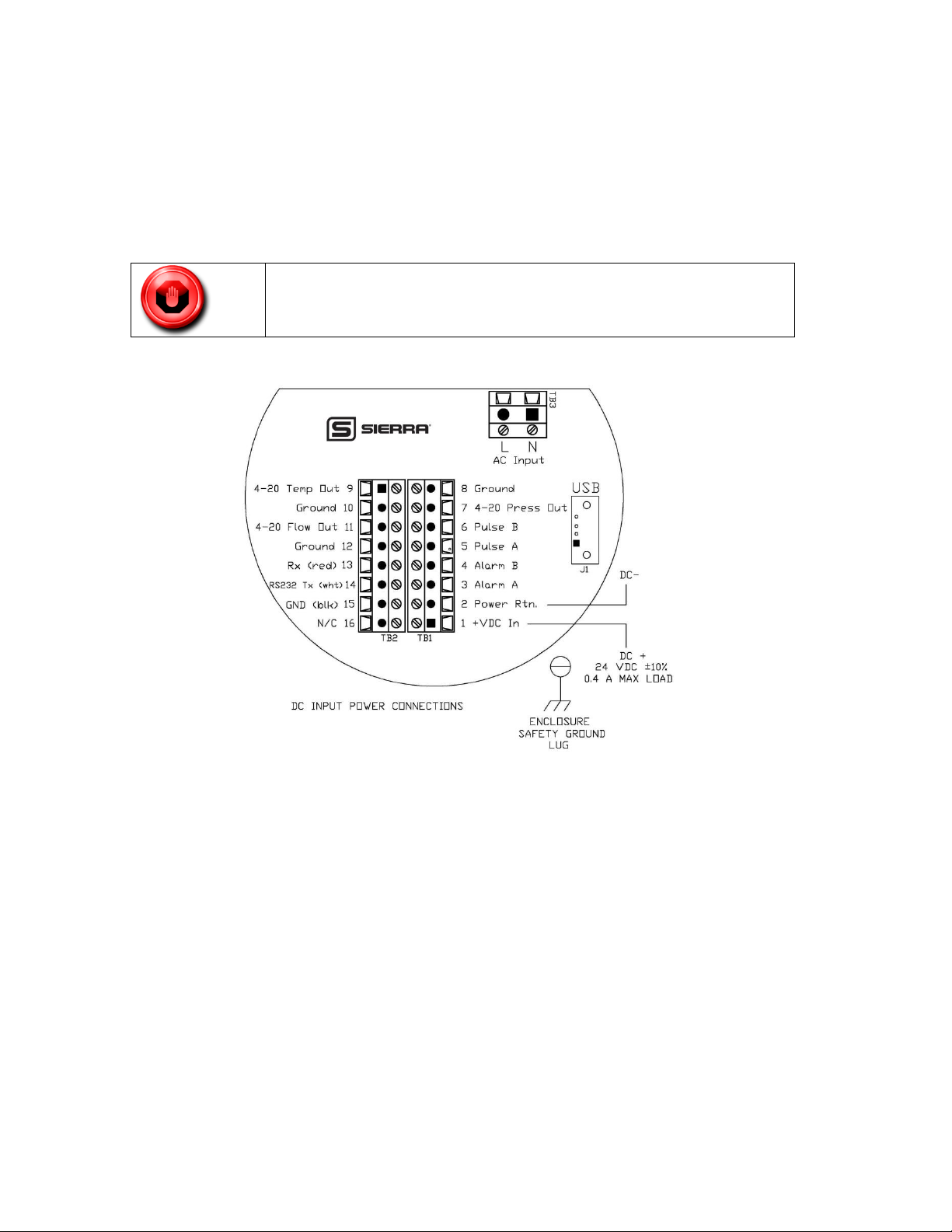
DC Power Wiring
All wiring procedures must be performed with the power off.
The DC power wire size must be 26 to 16 AWG with the wire stripped 1/4 inch (6 mm). Connect
24 VDC +/- 10% (0.4 amp load, maximum) to the terminals marked on the terminal block.
Connect the earth ground wire to the safety ground log. Torque all connections to 4.43 to 5.31 inlbs (0.5 to 0.6 Nm).
If conduit seals are used, they must be installed within 18 inches of the enclosure. See Figure
12.
Figure 12: DC Input Power Connections
Output Signal Wiring
You must use metal cable glands that provide cable screen clamping. The cable screen
should be connected to the gland and shielded at both ends over 360 degrees. The
shield should be terminated to an earth ground.
For all installations not using metal conduit, two ferrite beads should be added, one
on each end of the I/O cable. This is to maintain CE related EMI/RFI protection.
Good quality (highest impedance at 100MHz) broadband ferrites should be used; a
solid cylindrical ferrite (recommended) usually has better performance than a clamp
on ferrite. The ferrites should fit as tight as possible to the OD of your cable. See
Figure 14.
29
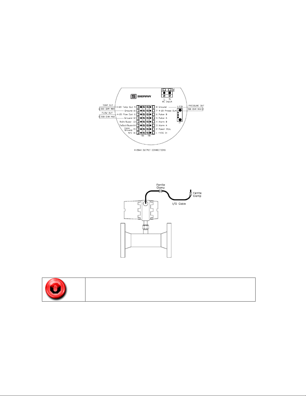
4-20 mA Output Wiring
Do not externally power the 4-20mA output loop. It is a self-powered
loop.
All InnovaMass 240i/241i Series flow meters are equipped with calibrated 4-20 mA output
signals for flow, temperature, and pressure.
The 4-20 mA current loop output is non-isolated. Max load 500 ohms.
Figure 13. 4-20mA Output Connections
Figure 14. Ferrite Installation (Ferrite not required for conduit)
Alarm Output Wiring
One alarm output contact is included on the flow meter terminal block. The alarm output is
driven by an optical relay that is normally-open single-pole. The relay is isolated and
requires a separate power supply (isolated). The voltage of the alarm output is the same as the
voltage supplied to the circuit.
To use an external power supply for an isolated alarm output, connect as shown in Figure 15.
You may set low, high or window alarms for temperature, pressure, totalizer, mass flow or
volumetric flow
.
30
 Loading...