


InnovaMass® 240i/241i Series BACnet
Instruction Manual
BACnet Device Specification for Models: 240i and 241i Volumetric & Multivariable Mass Vortex Flow Meter

Part Number: IM240i/241i BACnet Version V2 April 2018

Global Support Locations: We are here to help!
CORPORATE HEADQUARTERS
5 Harris Court, Building L Monterey, CA 93940 Phone (831) 373-0200 (800) 866-0200 Fax (831) 373-4402 info@sierrainstruments.com www.sierrainstruments.com
EUROPE HEADQUARTERS Bijlmansweid 2 1934RE Egmond aan den Hoef The Netherlands Phone +31 72 5071400 Fax +31 72 5071401 sales@sierrainstruments.nl
ASIA HEADQUARTERS
Second Floor Building 5, Senpu Industrial Park 25 Hangdu Road Hangtou Town Pu Dong New District, Shanghai, P.R. China Postal Code 201316 Phone: + 8621 5879 8521 Fax: +8621 5879 8586 orders@sierra-asia.com
For Global Service Centers, go to http://www.sierrainstruments.com/facilities.html
IMPORTANT CUSTOMER NOTICE- OXYGEN SERVICE
Sierra Instruments, Inc. is not liable for any damage or personal injury, whatsoever, resulting from the use of Sierra Instruments standard mass flow meters for oxygen gas. You are responsible for determining if this mass flow meter is appropriate for your oxygen application. You are responsible for cleaning the mass flow meter to the degree required for your oxygen flow application.
© COPYRIGHT SIERRA INSTRUMENTS 2018
No part of this publication may be copied or distributed, transmitted, transcribed, stored in a retrieval system, or translated into any human or computer language, in any form or by any means, electronic, mechanical, manual, or otherwise, or disclosed to third parties without the express written permission of Sierra Instruments. The information contained in this manual is subject to change without notice.
TRADEMARKS
InnovaFlo® and InnovaMass® are trademarks of Sierra Instruments, Inc. Other product and company names listed in this manual are trademarks or trade names of their respective manufacturers.
Warnings and Cautions
"Warning," "Attention," and "Note" statements are used throughout this manual to draw your attention to important information.
| Symbol Key | ||||
|---|---|---|---|---|
| Symbol |
Symbol
Meaning |
Descripition | ||
| Warning |
"Warning" statements appear with information that is important to
protect people and equipment from damage. Pay very close attention to all warnings that apply to your application. Failure to comply with these instructions may damage the meter and cause personal injury. |
|||
| ! | Caution |
"Attention" indicates that failure to comply with stated instructions
may result in damage or faulty operation of the meter. |
||
| (!) | Note | "Note" indicates that ignoring the relevant requirements or precautions may result in flow meter damage or malfunction. | ||

Warning! Agency approval for hazardous location installations varies between flow meter models. Consult the flow meter nameplate for specific flow meter approvals before any hazardous location installation.
Warning! Hot tapping must be performed by a trained professional. U.S. regulations often require a hot tap permit. The manufacturer of the hot tap equipment and/or the contractor performing the hot tap is responsible for providing proof of such a permit.
Warning! All wiring procedures must be performed with the power off.
Warning! To avoid potential electric shock, follow National Electric Code safety practices or your local code when wiring this unit to a power source and to peripheral devices. Failure to do so could result in injury or death. All AC power connections must be in accordance with published CE directives.
Warning! Do not power the flow meter with the sensor remote (if applicable) wires disconnected. This could cause over-heating of the sensors and/or damage to the electronics.
Warning! Before attempting any flow meter repair, verify that the line is de-pressurized.
Warning! Always remove main power before disassembling any part of the mass flow meter.

Caution! Before making adjustments to the device, verify the flow meter is not actively monitoring or reporting to any master control system. Adjustments to the electronics will cause direct changes to flow control settings.
Caution! All flow meter connections, isolation valves and fittings for hot tapping must have the same or higher-pressure rating as the main pipeline.
Caution! Changing the length of cables or interchanging sensors or sensor wiring will affect the accuracy of the flow meter. You cannot add or subtract wire length without returning the meter to the factory for recalibration.
Caution! When using toxic or corrosive gases, purge the line with inert gas for a minimum of four hours at full gas flow before installing the meter.
Caution! The AC wire insulation temperature rating must meet or exceed 80°C (176°F).
Caution! Printed circuit boards are sensitive to electrostatic discharge. To avoid damaging the board, follow these precautions to minimize the risk of damage:
- before handling the assembly, discharge your body by touching a grounded, metal object
- handle all cards by their edges unless otherwise required
- when possible, use grounded electrostatic discharge wrist straps when handling sensitive component
Receipt of System Components
When receiving a Sierra mass flow meter, carefully check the outside packing carton for damage incurred in shipment. If the carton is damaged, notify the local carrier and submit a report to the factory or distributor. Remove the packing slip and check that all ordered components are present. Make sure any spare parts or accessories are not discarded with the packing material. Do not return any equipment to the factory without first contacting Sierra Customer Service.
Technical Assistance
If you encounter a problem with your flow meter, review the configuration information for each step of the installation, operation, and setup procedures. Verify that your settings and adjustments are consistent with factory recommendations. Installation and troubleshooting information can be found in the InnovaMass 240i/241i Series Product Instruction Manual.
If the problem persists after following the troubleshooting procedures outlined in the 640S or 780S product manuals, contact Sierra Instruments by fax or by E-mail(see inside front cover). For urgent phone support you may call (800) 866-0200 or (831) 373-0200 between 8:00 a.m. and 5:00 p.m. PST. In Europe, contact Sierra Instruments Europe at +31 20 6145810. In the Asia-Pacific region, contact Sierra Instruments Asia at +86-21-58798521. When contacting Technical Support, make sure to include this information:
- The flow range, serial number, and Sierra order number (all marked on the meter nameplate)
- The software version (visible at start up)
- The problem you are encountering and any corrective action taken
- Application information (gas, pressure, temperature and piping configuration)
Register Your Product Today
Warranty Statement
All Sierra products are warranted to be free from defects in material and workmanship and will be repaired or replaced at no charge to Buyer, provided return or rejection of product is made within a reasonable period but no longer than one (1) year for calibration and non-calibration defects, from date of delivery. To assure warranty service, customers must register their products online on Sierra's website. Online registration of all of your Sierra products is required for our warranty process. Read complete warranty policy at www.sierrainstruments.com/warranty.
Register Warranty Online
Register now at www.sierrainstruments.com/register. Learn more about Sierra's warranty policy at www.sierrainstruments.com/warranty
Table of Contents
| Chapter 1: Introduction | 7 |
|---|---|
| BACnet MS/TP Description | 7 |
| Chapter 2: BACnet Installation | 8 |
| Overview 2-Wire Topology RS-485 Network | 8 |
| Electrical Connections | 9 |
| AC Power Wiring | 9 |
| DC Power Wiring. | 10 |
| Connecting the RS-485 Network Wires | .11 |
| Cable | 11 |
| Terminator | 12 |
| Line Polarization | 12 |
| Shield Wire Grounding | 12 |
| Cabling & Wiring Do's and Don'ts | 12 |
| Chapter 3: InnovaMass 240i/241i Com Settings | .14 |
| Baud Rate and MAC Address Configuration | .14 |
| Chapter 4: Supported BACnet Services/Objects | .16 |
| Acronyms and Definitions | .17 |
| BACnet Supported Device, Object & Property Table | .18 |
| Chapter 5: Engineering Units | .25 |
| Units Not Supported by BACnet | 25 |
| Chapter 6: Troubleshooting Tips | .27 |
| Other Troubleshooting Tips | 28 |
Chapter 1: Introduction
This manual will explain the function and operation of the optional BACnet interface for Sierra Instruments InnovaMass® 240i/241i iSeries vortex mass flow meter.
This document is intended to be a complement to other 240i/241i® documentation by providing a complete description of the InnovaMass iSeries from a BACnet communication perspective. It is also intended to be a technical reference for BACnet capable host application developers, system integrators and knowledgeable end users. This manual assumes the reader already has a working knowledge of BACnet protocol requirements and terminology. For specific operations of the InnovaMass 240i and 241i vortex flow meter, consult the InnovaMass 240i/241i iSeries Instruction manual.
BACnet MS/TP Description
BACnet is a communications protocol for Building Automation and Control (BAC) networks that is governed by the American Society of Heating, Refrigerating and Air-Conditioning Engineers (ASHRAE), SSPC 135, ANSI, and ISO 16484-5 standard protocol.
The BACnet Master---slave/token-passing (MS/TP) driver implements a data link protocol that uses the services of the RS-485 physical layer. The MS/TP bus is based on BACnet standard protocol SSPC-135, Clause 9. BACnet MS/TP protocol is a peer-to-peer, multiple master protocols based on token passing. Only master devices can receive the token, and only the device holding the token is allowed to originate a message on the bus. The token is passed from master to master using a small message in consecutive order starting with the lowest address. Slave devices on the bus only communicate on the bus when responding to a data request from a master device.

Caution!
To fully understand the InnovaMass and its functions please read the InnovaMass instruction manual.
Chapter 2: BACnet Installation
Overview 2-Wire Topology RS-485 Network
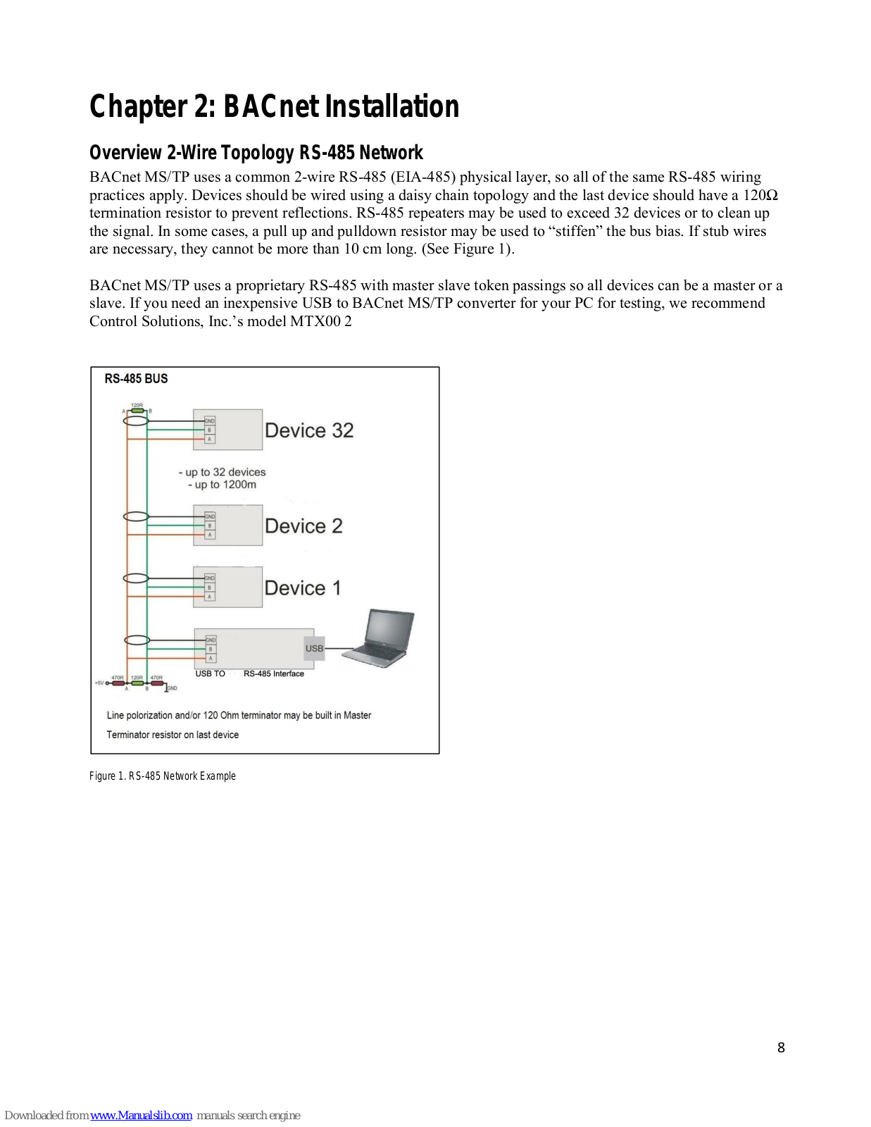
BACnet MS/TP uses a common 2-wire RS-485 (EIA-485) physical layer, so all of the same RS-485 wiring practices apply. Devices should be wired using a daisy chain topology and the last device should have a 120Ω termination resistor to prevent reflections. RS-485 repeaters may be used to exceed 32 devices or to clean up the signal. In some cases, a pull up and pulldown resistor may be used to "stiffen" the bus bias. If stub wires are necessary, they cannot be more than 10 cm long. (See Figure 1).
BACnet MS/TP uses a proprietary RS-485 with master slave token passings so all devices can be a master or a slave. If you need an inexpensive USB to BACnet MS/TP converter for your PC for testing, we recommend Control Solutions, Inc.'s model MTX00 2

Figure 1. RS-485 Network Example
Electrical Connections-Input
All electrical connections are made on the terminal board inside the InnovaMass enclosure. For detailed instructions on installing your InnovaMass iSeries meter, please read the InnovaMass 240i/241i Instruction Manual. For complete wiring instructions please see Chapter 2 of the 240i/241i instruction manual.
Input Power Wiring
AC Power Wiring
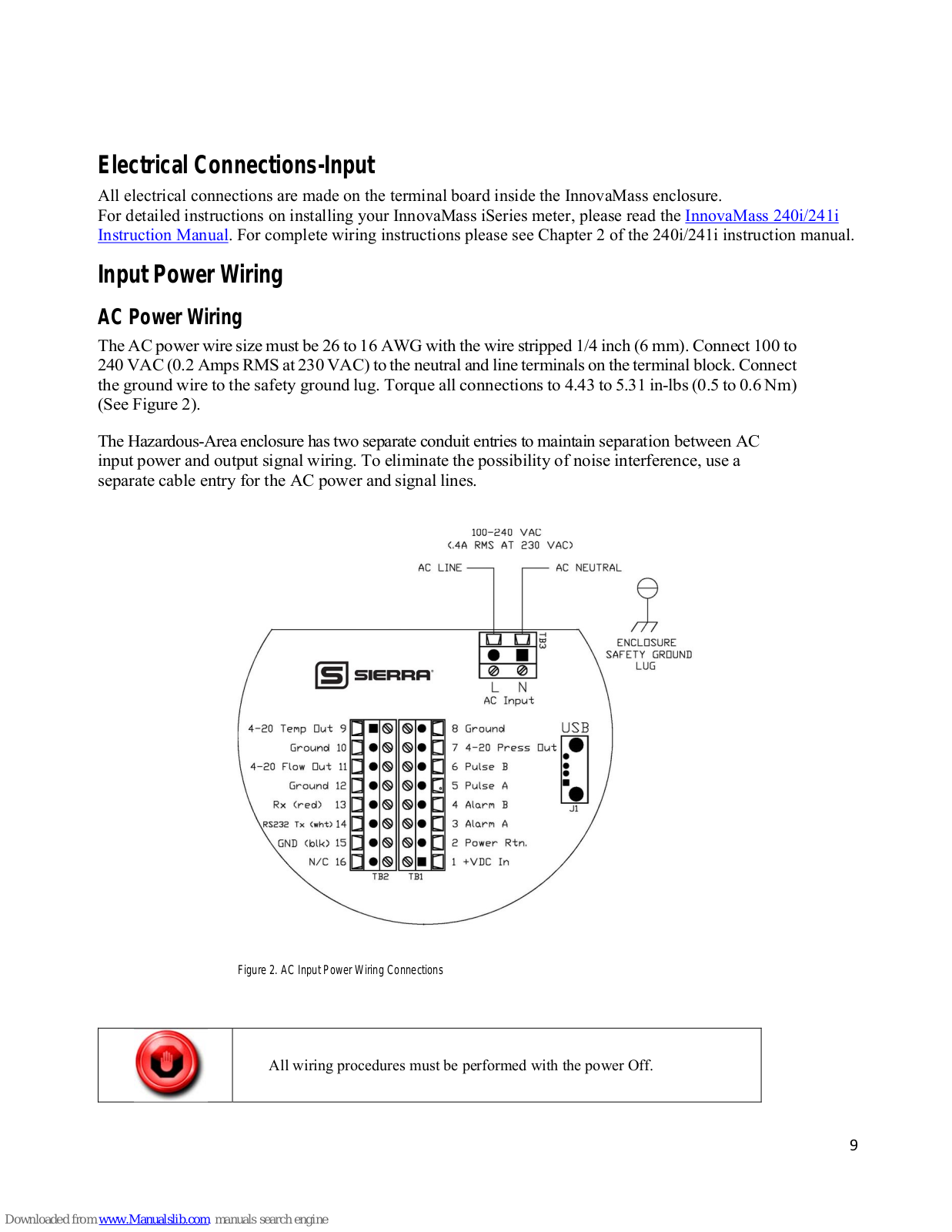
The AC power wire size must be 26 to 16 AWG with the wire stripped 1/4 inch (6 mm). Connect 100 to 240 VAC (0.2 Amps RMS at 230 VAC) to the neutral and line terminals on the terminal block. Connect the ground wire to the safety ground lug. Torque all connections to 4.43 to 5.31 in-lbs (0.5 to 0.6 Nm) (See Figure 2).
The Hazardous-Area enclosure has two separate conduit entries to maintain separation between AC input power and output signal wiring. To eliminate the possibility of noise interference, use a separate cable entry for the AC power and signal lines.

Figure 2. AC Input Power Wiring Connections

All wiring procedures must be performed with the power Off

The AC wire insulation temperature rating must meet or exceed 80 °C (176°F).
DC Power Wiring
The DC power wire size must be 26 to 16 AWG with the wire stripped 1/4 inch (6 mm). Connect 24 VDC +/-10% (0.4 amp load, maximum) to the terminals marked on the terminal block. Connect the earth ground wire to the safety ground log. Torque all connections to 4.43 to 5.31 in-lbs (0.5 to 0.6 Nm). See Figure 3.
If conduit seals are used, they must be installed within 18 inches of the enclosure.

Figure 3. DC Input Power Wiring Connections

Connecting the RS-485 Network Wires

Caution!
The InnovaMass is equipped with an optical isolated RS-485 interface. Grounding the RS-485 common (15) would defeat this.
- 1. Connect your 2-wire RS-485 network to terminal 13 (A-) and your wire RS-485 to terminal 14 (B+).
- 2. Connect the RS-485 common (sheild wire) to terminal Com 15 (See Figure 4).

Figure 4. BACnet RS-485 Network Wire Connection
Cable
It is recommended that you use a shielded twisted pair type of cable (reduces radiated and received EMI). Use a 24 AWG shielded twisted pair cable, with low capacitance like Belden 9841.
Terminator
Reflections in a transmission line can cause communication errors. To minimize the reflection, it is required to place 120Ω terminator resistors at both ends of the cable. Never place a terminator resistor somewhere along the cable. Some gateways, PLCs, and other types of devices have terminator resistors built-in. If so, do not add another one. Using an Oscilloscope, you can see what a reflection looks like, and how it can confuse the data (See Figure 5):

Figure 5 Reflections in Transmission Line
Line Polarization
RS-485 uses three voltage levels, "1", "0", and idle. In noisy environments, it may be necessary to polarize the lines to ensure that the receivers stay in a constant state when the idle "no signal" is present. In most cases, the master does this already.
Commercially available isolated RS-485 repeaters in the middle of your wire run will "clean up" the signals and polarize the idle voltage. This is very useful for long wire runs and noisy environments.
Shield Wire Grounding
We use a RS-485 chip that has 1,5000 volts of isolation (See Figure 4). For electrical noise, it's best to keep the shield wire isolated from Earth ground and only connect it to terminal 16 and the signal ground at the Master.
Occasionally, you may have no choice but to share the network with a device that has a non-isolated RS-485 chip. Usually, you can get by with this. If you still have trouble, you may need to use an isolated RS-485 repeater to separate it from the rest of the network.
Summary: Cabling & Wiring Do's and Don'ts
- 1. Use a 24 AWG shielded twisted pair cable, with low capacitance, 120Ω impedance like Belden 9841.
- 2. Never put the RS-485 wires in the same conduit as AC power. Ideally, DC power wires should be run in separate conduit if possible to prevent interference issues.
- 3. Both ends of the RS-485 network cable should have 120 Ω resistors to prevent reflections. Before the network is running you should be able to verify this with a simple DMM. You should measure about 60Ω total. (Two 120Ω resistors in parallel)
- 4. Terminals A- and B+ connections will be connected to the twisted wire pair in the center of the cable.
- 5. The cable shield wire needs be connected terminal C. It's better if the shield it is not connected to Earth ground. However, some other RS-485 devices on your network may already Earth grounded this shield. This is still acceptable, but it's best that this device is near the master.
- 6. Wires between RS-485 devices need to be wired in a daisy-chain pattern. They should never be wired with separate home-runs back to the master in a Star pattern. When daisy chaining the Modbus A/B wires you should either twist the wires together and solder or use a crimp ferrule, this would still allow the bus to be connected even if the meter A/B wires were disconnected at one 240i.
- 7. Keep the wires as short as possible inside the enclosure and maintain the wire twist as much as possible.
-
8. The meter enclosure should always be Earth grounded. This prevents Electrostatic and Electromagnetic noise from interfering with the meter's microprocessor or the BACnet data. In addition, it also provides for safety, EMI, RFI, and ESD protection. Both the main and remote (if E4 option ordered) enclosures should be connected to Earth ground, see below for more details.
- A. External Earth Grounding: The external Earth connections are located on the boss on the outside of both the main housing and remote housing (E4 option if ordered) and consist of an 18-8SS pan head Phillips screw (10-24 UNC-2B thread) and a serrated tooth #10 ring terminal for 16-14 AWG wire.
- B. Internal Earth Grounding: The internal Earth connection is located in the main housing terminal side and consist of an 18-8SS pan head Phillips screw (10-24 UNC-2B thread) and a serrated tooth #10 ring terminal for 16-14 AWG wire.
Chapter 3: InnovaMass 240i/241i Com Settings
The BACnet MS/TP bus can be configured using the InnovaMass 240i/241i SIP. It can communicate at one of three baud rates: 9600, 19200 and 38400. It is very important that all of the devices on the MS/TP bus be set to communicate at the same baud rate.
Baud Rate and MAC Address Configuration
The Baud rate and MAC (MS/TP) address are changed using the Smart Interface Portal (SIP) software. Download software at http://www.sierrainstruments.com/products/sip/sip-innovamass.html. Once the SIP software is installed, select "Hardware Configuration" from the dropdown list (See Figure 6). In the "Hardware Configuration" screen, select available MS/TP Baud rates are 9600, 19200 and 38400. The "MS/TP MAC Address" of 1 to 127 may be selected (See Figure 6).

Figure 6. InnovaMass 240i/241i SIP Main Menu Dropdown
| SS 24 | 01/24 | 11 |
(
|
||||
|---|---|---|---|---|---|---|---|
| IETER DISPLAY |
Docume
MEI Hardware Co |
nts and Downloa
TER CONTROL Infiguration |
25 | ||||
|
Relay "A"
Off Force On Totalizer Pulse Row Alarm Temperature Alarm Pressure Alarm Totalizer Alarm Reloar |
Relay "B"
Off Force On Totalizer Pulse Row Alam Temperature Alam Pressure Alam Totalizer Alam |
USB UART
Display UART Display UART MSTP Baud MSTP Address Terminal UART |
UART Emulation
Default Default 38400 2 Default |
MS Delay | Frame Delay 1 50 10 10 1 | Locked | |
| ure 7. InnovaMass Si | P Hardware Configur | ation Menu | **** |
Select Port:
MS/TP |
сома | ~ |
Chapter 4: Supported BACnet Services/Objects
A BACnet object represents physical or virtual equipment information, as a digital input or parameters. The InnovaMass 240i/241i Series vortex mass flow meter uses the following object types:
- a. Device Object (1)
- b. Analog Input (21)
- c. Binary Input (10)
- d. Binary Output (1)
Each object type defines a data structure composed by properties that allow the access to the object information. The table on the following pages shows the implemented properties for each InnovaMass 240i/241i Vortex Mass Flow Meter object type.
| Supported BACnet Services/Objects | |||||
|---|---|---|---|---|---|
| BACnet Interoperability Building Blocks | Services | Support | |||
| DS-RP-B | Read Property | Execute | |||
| DS-WP-B | Write Property | Execute | |||
| DM-DDB-B | Read Property Multiple | Execute | |||
| DM-DOB-B | Write Property Multiple | Execute | |||
| DM-DCC-B | Who-Is | Execute | |||
| DS-RPM-B | IAm | Initiate | |||
| DS-WPM-B | Who-Has | Execute | |||
| I-Have | Initiate | ||||
| Device Communication Control | Execute | ||||
Supported BACnet Services/Objects
Acronyms and Definitions
| Acronyms and Definitions | ||||
|---|---|---|---|---|
| Item | Description | |||
| APDU | Application Protocol Data Unit | |||
| BACnet | Building Automation and Control Network Data communication protocol | |||
| MS/TP | MasterSlave Token passing (a twisted pair RS485 network created by BACnet) | |||
| BIBB | BACnet Interoperability Building Block (Specific individual function blocks for data exchange | |||
| BV | Binary Value | |||
| BI | Binary Input | |||
| AI | Analog Input | |||
| RP | Read Property | |||
| WP | Write Property | |||
| RPM | Read Property Multiple | |||
| WPM | Write Property Multiple. | |||
| DDB | Dynamic Device Binding | |||
| DOB | Dynamic Object Binding | |||
| DCC | Device communication Control | |||
BACnet Supported Device, Object & Property Table
| BACnet Object Name | Obj, Instance | BACnet Object Property | Default/Sample Values |
|---|---|---|---|
| Object Identifier | MAC | ||
| Object Name | 240i Flowmeter | ||
| Object Type | Flowmeter | ||
| System Status | Operational | ||
| Vendor Name | Sierra Instruments | ||
| Vendor Identifier | ASHRA# 722 | ||
| Model Name | 240i | ||
| Firmware Revision | v1.2.07 | ||
| Application Software Version | v1.2.07 | ||
| Location | NULL | ||
| Description | NULL | ||
| Device1 | Day 1 | Protocol Version | 1 |
| Device1 | Dev, 1 | Protocol Revision | 12 |
| Protocol Services Supported | |||
| Protocol Object Types Supported | |||
| Object List | |||
| Max APDU Length Accepted | 480 | ||
| Segmentation Supported | No | ||
| APDU Timeout | 6000 | ||
| Number Of APDU Retries | 3 | ||
| Max Master | 127 | ||
| Max Info Frames | 1 | ||
| Device Address Binding | |||
| Database Revision | 0 | ||
| Object Identifier | AI-1 | ||
| Object Name | Flow | ||
| Object Type | Analog Input | ||
| Present Value | 1 | ||
| Flow | AI, 1 | Description | Used for measurement of Flow |
| Status Flags | F,F,F,F { } | ||
| Event State | NORMAL | ||
| Out Of Service | 0 | ||
| Units | cubic_feet_per_minute | ||
| BACnet Object Name | Obj, Instance | BACnet Object Property | Default/Sample Values |
|---|---|---|---|
| Object Identifier | AI-2 | ||
| Object Name | Temperature1 | ||
| Object Type | Analog Input | ||
| Present Value | 70 | ||
| Temperature1 | AI, 2 | Description | Int. Temperature |
| Status Flags | F,F,F,F { } | ||
| Event State | NORMAL | ||
| Out Of Service | 0 | ||
| Units | degrees_fahrenheit | ||
| Object Identifier | AI-3 | ||
| Object Name | Temperature2 | ||
| Object Type | Analog Input | ||
| Present Value | 123.4 | ||
| Temperature2 | AI, 3 | Description | Ext. Temperature |
| Status Flags | F,F,F,F { } | ||
| Event State | NORMAL | ||
| Out Of Service | 0 | ||
| Units | degrees_fahrenheit | ||
| Object Identifier | AI-4 | ||
| Object Name | Pressure | ||
| Object Type | Analog Input | ||
| Present Value | 14.7 | ||
| Pressure | AI, 4 | Description | Fluid Pressure |
| Status Flags | F,F,F,F { } | ||
| Event State | NORMAL | ||
| Out Of Service | 0 | ||
| Units | pounds_per_square_inch | ||
| Object Identifier | AI-5 | ||
| Object Name | Energy Flow | ||
| Object Type | Analog Input | ||
| Present Value | 1 | ||
| Energy Flow | AI,5 | Description | Energy Flow in Fluid |
| Status Flags | F,F,F,F { } | ||
| Event State | NORMAL | ||
| Out Of Service | 0 | ||
| Units | btus | ||
| Object Identifier | AI-6 | ||
| Object Name | Totalizer | ||
| Object Type | Analog Input | ||
| Present Value | 1235 | ||
| Totalizer | AI,6 | Description | Flow Totalizer |
| Status Flags | F,F,F,F { } | ||
| Event State | NORMAL | ||
| Out Of Service | 0 | ||
| Units | cubic_feet |
| BACnet Object Name | Obj, Instance | BACnet Object Property | Default/Sample Values |
|---|---|---|---|
| Object Identifier | AI-7 | ||
| Object Name | Alarm Status | ||
| Object Type | Analog Input | ||
| Present Value | 0 | ||
| Alarm Status | AI,7 | Description | State of Alarm Relay |
| Status Flags | F,F,F,F { } | ||
| Event State | NORMAL | ||
| Out Of Service | 0 | ||
| Units | No units | ||
| Object Identifier | AI-8 | ||
| Object Name | Alarm Active | ||
| Object Type | Analog Input | ||
| Present Value | 0 | ||
| Alarm active | AI,8 | Description | Source of Alarm |
| Status Flags | F,F,F,F { } | ||
| Event State | NORMAL | ||
| Out Of Service | 0 | ||
| Units | No units | ||
| Object Identifier | AI-9 | ||
| Object Name | Alarm Mode | ||
| Object Type | Analog Input | ||
| Present Value | 0 | ||
| Alarm mode | AI,9 | Description | Selected Alarm Mode |
| Status Flags | F,F,F,F { } | ||
| Event State | NORMAL | ||
| Out Of Service | 0 | ||
| Units | No units | ||
| Object Identifier | AI-10 | ||
| Object Name | Velocity | ||
| Object Type | Analog Input | ||
| Present Value | 1 | ||
| Velocity | AI,10 | Description | Point vol. Velocity |
| Status Flags | F,F,F,F { } | ||
| Event State | NORMAL | ||
| Out Of Service | 0 | ||
| Units | feet_per_second | ||
| Object Identifier | AI-11 | ||
| Object Name | Flow-Pro | ||
| Object Type | Analog Input | ||
| Present Value | 1 | ||
| Flow-Pro | AI,11 | Description | Correction Factor |
| Status Flags | F,F,F,F { } | ||
| Event State | NORMAL | ||
| Out Of Service | 0 | ||
| Units | No units |
Object Identifier
Al-12
Object Name
Density
Object Type
Analog Input
Present Value
1
Description
Density for mass
Status Flags
F,F,F,F {}
Event State
NORMAL
Out of Service
0
Units
No units
Object Identifier
Al-13
Object Type
Analog Input
Present Value
1
0 bject Identifier
Al-13
Object Type
Analog Input
Present Value
1
Description
Reynolds
Al,13
Description
Description
Reynolds number
Status Flags
F,F,F,F {}
Event State
NORMAL
OUt Of Service
0
Units
No units
Object Vare
Analog Input
Present Value
1
Description
Dynamic Viscosity
Object Vare
Analog Input
Present Value
|
BACnet Object Name
|
Obj, Instance
|
BACnet Object Property
|
Default/Sample Values
|
|
|---|---|---|---|---|
Object Name
Density
Al,12
Description
Density for mass
Status Flags
F,F,F,F ()
Event State
NORMAL
Outiest
No units
Object Identifier
Al-13
Object Identifier
Al-13
Object Varee
0
Units
No units
Object Varee
Analog Input
Present Value
1
Object Varee
Analog Input
Present Value
1
Object Varee
Analog Input
Present Value
1
Description
Reynolds number
Status Flags
F,F,F,F ()
Event State
NORMAL
Out of Service
0
Units
No units
Object Identifier
Al-14
Object Varee
Analog Input
Present Value
1
Viscosity
Al,14
Description
Dynamic Viscosity
Status Flags
F,F,F,F ()
Event State
NORMAL
|
|
|
Object Identifier
|
AI-12
|
|
| Density Al,12 Description Density for mass Density Al,12 Description Density for mass Status Flags F,F,F,F { } Event State NORMAL Out Of Service 0 Units No units Object Identifier Al-13 Object Type Analog input Present Value 1 Description Reynolds Al,13 Description Reynolds Diget Identifier Description Reynolds number Status Flags F,F,F,F { } Event State NORMAL Out of Service O Out of Service 0 O Out of Service Out of Service 0 O Out of Service Object Identifier Al-14 Object Type Analog input Viscosity Al,14 Description Dymaic Viscosity Object Identifier Al-14 Object Type Analog input Viscosity Al,14 Description Dymaic Viscosity Object Type Analog input Present Value | Object Name | Density | ||
| Pensity Ai,12 PresentValue 1 Density Ai,12 Description Density for mass Status Flags F,F,F,F (1) Event State NORMAL Out Of Service 0 Units No units Object Varue 0 Object Varue 1 Present Value 1 Description Reynolds number Status Flags F,F,F,F (1) Event State NORMAL Out Of Service 0 Units No units Object Varue 1 Viscosity Al,14 Description No units Object Varue 1 Viscosity Al,14 Description Dynamic Viscosity Viscosity Al,14 Description Dynamic Viscosity Viscosity Al,14 Description Dynamic Viscosity Status Flags F,F,F,F (1) Event State NORMAL Out Of Service 0 Units 423 Object Type Anal | Object Type | Analog Input | ||
| Density Al,12 Description Density for mass Status Flags F,F,F,F { } Event State NORMAL Out Of Service 0 Units No units Object Identifier Al-13 Description Reynolds number Status Flags F,F,F,F { } Event State NORMAL Out Of Service 0 Out Of Service 0 Units No units Viscosity Al,14 Description Dynamic Viscosity Object Identifier Al-14 Object Rame Viscosity Object Rame Viscosity Viscosity Al,14 Description Dynamic Viscosity Out Of Service 0 Out Of Service 0 Out Of Service 0 Object Name F,F,F,F { } Event State NORMAL Object Wame Frequency Object Name Frequency Object Identifier Al-15 | Present Value | 1 | ||
| Status Flags F,F,F,F {} Event State NORMAL Out Of Service 0 Units No units Object Identifier Ai-13 Object Name Reynolds Object Type Analog Input Present Value 1 Description Reynolds number Status Flags F,F,F,F {} Event State NORMAL Out of Service 0 Units No units Object Identifier Ai-14 Object Type Analog Input Present Value 1 Viscosity Ai,14 Description Dynamic Viscosity Status Flags F,F,F,F {} Event State NORMAL Out Of Service 0 Units 423 Object Identifier Ai-15 Object Name Frequency Object Name Frequency Object Identifier Ai-15 Object Name Frequency | Density | AI,12 | Description | Density for mass |
| Event State NORMAL Out Of Service 0 Units No units Object Identifier Al-13 Object Type Analog Input Present Value 1 Description Reynolds number Status Flags F, F (1) Event State NORMAL Out Of Service 0 Units No units Viscosity Al,14 Object Identifier Al-14 Object Identifier Al-15 Out of Service 0 Units 423 Out of Service 0 Units 423 Object Identifier Al-15 Object Identifier Al-15 Object Identifier | Status Flags | F,F,F,F { } | ||
| Out Of Service 0 Units No units Object Identifier AI-13 Object Name Reynolds number Fresent Value 1 Present Value 1 Description Reynolds number Status Flags F,F,F,f {} Event State NORMAL Out Of Service 0 Units No units Object Identifier AI-14 Object Type Analog Input Present Value 1 Description Dynamic Viscosity Status Flags F,F,F,F {} Event State NORMAL Out Of Service 0 Units 423 Object Identifier AI-15 Object Name Frequency AI,15 Description Vortex shedder frequency | Event State | NORMAL | ||
| Units No units Object Identifier AI-13 Object Type Analog Input Present Value 1 Description Reynolds number Status Flags F,F,F,F { } Event State NORMAL Out Of Service 0 Units No units Object Identifier AI-14 Object Type Analog Input Present Value 1 Object Identifier AI-14 Object Type Analog Input Present Value 1 Description Dynamic Viscosity Viscosity AI,14 Description Description Dynamic Viscosity Status Flags F,F,F,F { } Event State NORMAL Out Of Service 0 Units 423 Object Type Analog Input Present Value 1 Description Vortex shedder frequency | Out Of Service | 0 | ||
| Beynolds Al,13 Object Identifier Al-13 Reynolds Al,13 Description Reynolds Analog input Present Value 1 Description Reynolds number 3 Status Flags F,F,F,F { } 1 Event State NORMAL 0 Out Of Service 0 0 Units No units No Viscosity Al,14 Description Description Viscosity Al,14 Description Dynamic Viscosity Viscosity Al,14 Description Dynamic Viscosity Status Flags F,F,F,F { } Event State NORMAL Out Of Service 0 Object Identifier Al-15 0 0 Object Name Frequency Object Name Frequency Al,15 Description Vortex shedder frequency Object Name Frequency Disct Identifier Al-15 Object Name Frequency | Units | No units | ||
| Reynolds Al,13 Object Name Reynolds (piput) Reynolds Al,13 Description Reynolds number Status Flags F,F,F,F {} Event State NORMAL Out Of Service 0 Units No units No units 0 Viscosity Al,14 Object Identifier Al-14 Object Name Viscosity Object Identifier Al-14 Object Type Analog Input Present Value 1 Viscosity Al,14 Description Dynamic Viscosity Status Flags F,F,F,F {} Event State NORMAL Out Of Service 0 Units 423 0 Viscosity Al,15 Object Identifier Al-15 0 Object Identifier Al-15 0 Viscosity Al,15 Description Vortex shedder frequency Object Identifier Al-15 0 0 < | Object Identifier | AI-13 | ||
| Reynolds Al,13 Object Type Analog Input Present Value 1 | Object Name | Reynolds | ||
| Reynolds Al,13 Present Value 1 Description Reynolds number Status Flags F,F,F,F { } Event State NORMAL Out Of Service 0 Units No units Object Identifier Al-14 Object Rame Viscosity Object Identifier Al-14 Object Rame Viscosity Object Rame Viscosity Status Flags F,F,F,F { } Event State NORMAL Out Of Service 0 Units 423 Object Identifier Al-15 Object Type Analog Input Present Value 1 Description Vortex shedder frequency Object Type Analog Input Present Value 1 Description Vortex shedder frequency Object Type Analog Input Present Value 1 Description Vortex shedder frequency Object Type Analog Input< | Object Type | Analog Input | ||
| Reynolds Al,13 Description Reynolds number Status Flags F,F,F,F { } Event State NORMAL Out Of Service 0 Units No units 0bject Identifier Al-14 Object Type Analog Input Present Value 1 Viscosity Al,14 Description Dynamic Viscosity Viscosity Al,14 Description Dynamic Viscosity Status Flags F,F,F,F { } Event State NORMAL Out Of Service 0 0 Units 423 Object Ivpe Analog Input Present Value 1 Description Frequency Al,15 Description Vortex shedder frequency Object Identifier Al-15 Object Type Analog Input Present Value 1 Description Vortex shedder frequency Status Flags F,F,F,F { } Event State NORMAL Out Of Service 0 Units hertz 0 Votex shedder frequency 0 | Present Value | 1 | ||
| Status Flags F,F,F,F { } Event State NORMAL Out of Service 0 Units No units Object Identifier Al-14 Object Name Viscosity Object Type Analog Iput Present Value 1 Event State NORMAL Out of Service 0 Out of Service 0 Units 423 Object Identifier Al-15 Out of Service 0 Out of Service 0 Units 423 Object Identifier Al-15 Object Name Frequency Object Type Analog Input Present Value 1 Durits Halt Event State NORMAL Out of Service 0 Units Halt Object Identifier Al-16 Out of Service 0 Units Halt Object Name Fr,F,F,F {} Event State NORMAL | Reynolds | AI,13 | Description | Reynolds number |
| Event State NORMAL Out Of Service 0 Units No units Object Identifier Al-14 Object Type Analog Input Present Value 1 Description Dynamic Viscosity Out of Service 0 Out of Service 0 Out of Service 0 Units 423 Object Identifier Al-15 Object Type Analog Input Present Value 1 Present Value 1 Description Vortex shedder frequency Object Type Analog Input Present Value 1 Description Vortex shedder frequency Object Type Analog Input Present Value 1 Out of Service 0 Units hertz Object Identifier | Status Flags | F,F,F,F { } | ||
| Out Of Service 0 Units No units Object Identifier AI-14 Object Name Viscosity Object Type Analog Input Present Value 1 Description Dynamic Viscosity Status Flags F,F,F,F {} Event State NORMAL Out of Service 0 Units 423 Object Identifier AI-15 Object Identifier AI-15 Object Type Analog Input Present Value 1 Present Value 1 Object Identifier AI-15 Object Type Analog Input Present Value 1 Description Vortex shedder frequency Object Type Analog Input Present Value 1 Description Vortex shedder frequency Status Flags F,F,F,F {} Event State NORMAL Out of Service 0 Units hertz Object Name | Event State | NORMAL | ||
| UnitsNo unitsViscosityAl-14Object IdentifierAl-14Object NameViscosityObject TypeAnalog InputPresent Value1DescriptionDynamic ViscosityStatus FlagsF,F,F,F {}Event StateNORMALOut of Service0Units423Object TypeAnalog InputPresent Value1Object NameFrequencyObject TypeAnalog InputPresent Value1Object TypeAnalog InputPresent Value1DescriptionVortex shedder frequencyObject TypeAnalog InputPresent Value1DescriptionVortex shedder frequencyStatus FlagsF,F,F {}Event StateNORMALOut of Service0UnitshertzObject IdentifierAl-16Object NameCk factorObject TypeAnalog InputPresent Value20Ck factorAl,16DescriptionFor dynamic freq.Status FlagsF,F,F,F {}Event StateNORMALOut Of Service0UnitsFor dynamic freq.Status FlagsF,F,F,F {}Event StateNORMALOut Of Service0UnitsNo units | Out Of Service | 0 | ||
| Viscosity Al,14 Object Identifier Al-14 Object Name Viscosity Object Type Analog Input Present Value 1 Description Dynaic Viscosity Status Flags F,F,F,F {} Event State NORMAL Out Of Service 0 Units 423 Object Identifier Al-15 Object Name Frequency Al,15 Description Vortex shedder frequency Object Identifier Al,15 Description Vortex shedder frequency Status Flags Frequency Al,15 Description Vortex shedder frequency Status Flags F,F,F,F {} Event State NORMAL Out Of Service 0 Units hertz Object Identifier Al-16 Object Type Analog Input Present Value 20 Ck factor Object Name Ck factor Object Type Analog Input Present Value Description | Units | No units | ||
| Viscosity Al,14 Object Name Viscosity Viscosity Al,14 Description Dynamic Viscosity Status Flags F,F,F,F {} Event State NORMAL Out of Service 0 0 Units 423 Object Type Analog Input Present Value 1 Frequency Al,15 Object Identifier Al-15 Object Type Analog Input Present Value 1 Present Value 1 1 Description Vortex shedder frequency Object Type Analog Input Present Value Present Value 1 1 Description Vortex shedder frequency Status Flags F,F,F,F {} Event State NORMAL Out Of Service 0 0 Units hertz Object Identifier Al-16 Object Name Ck factor Object Name Ck factor Object Type Analog Input Present Value 20 Description Status Flags F,F,F,F {} Event State NORMAL Out Of Service 0 Out Of Service 0 | Object Identifier | AI-14 | ||
| Viscosity Al,14 Object Type Analog Input Present Value 1 Description Dynamic Viscosity Status Flags F,F,F,F {} Event State NORMAL Out Of Service 0 Units 423 Object Identifier Al-15 Object Name Frequency Object Type Analog Input Present Value 1 Present Value 1 Object Identifier Al-15 Object Type Analog Input Present Value 1 Out Of Service 0 Out Of Service 0 Object Identifier Al-16 Object Name Ck factor Object Name Ck factor Object Name Ck factor Object Name Ck factor Object Name Ck factor Object Type Analog Input< | Object Name | Viscosity | ||
| Viscosity Al,14 Present Value 1 Viscosity Al,14 Description Dynamic Viscosity Status Flags F,F,F,F {} Event State NORMAL Out Of Service 0 Units 423 Object Identifier Al-15 Object Name Frequency Object Type Analog Input Present Value 1 Present Value 1 Description Vortex shedder frequency Object Identifier Al-15 Object Type Analog Input Present Value 1 Description Vortex shedder frequency Status Flags F,F,F,F {} Event State NORMAL Out Of Service 0 Units hertz Object Identifier Al-16 Object Name Ck factor Object Type Analog Input Present Value 20 Ck factor Al,16 Description For dynamic freq. Status Flags F,F,F,F {} Event State< | Object Type | Analog Input | ||
| Viscosity Al,14 Description Dynamic Viscosity Status Flags F,F,F,F { } Event State NORMAL Out Of Service 0 Units 423 Object Identifier Al-15 Object Vame Frequency Object Vame Al-15 Object Type Analog Input Present Value 1 Description Vortex shedder frequency Status Flags F,F,F,F { } Event State NORMAL Out Of Service 0 Units hertz Object Identifier Al-16 Object Name Ck factor Object Identifier Al-16 Object Type Analog Input Present Value 20 Units hertz Object Type Analog Input Present Value 20 Ck factor Al,16 Description For dynamic freq. Status Flags F,F,F,F { } Event State NORMAL Out of Service 0 Units | Present Value | 1 | ||
| Status Flags F,F,F,F { } Event State NORMAL Out Of Service 0 Units 423 Object Identifier Al-15 Object Name Frequency Object Type Analog Input Present Value 1 Description Vortex shedder frequency Status Flags F,F,F,F { } Event State NORMAL Out Of Service 0 Units hertz Object Identifier Al-16 Object Status Flags F,F,F,F { } Event State NORMAL Out Of Service 0 Units hertz Object Identifier Al-16 Object Type Analog Input Present Value 20 Ck factor Al,16 Description For dynamic freq. Status Flags F,F,F,F { } Event State NORMAL Out Of Service 0 Uut of Service 0 Uut of Service 0 Uut of Service 0 | Viscosity | AI,14 | Description | Dynamic Viscosity |
| Event State NORMAL Out Of Service 0 Units 423 Object Identifier Al-15 Object Name Frequency Object Type Analog Input Present Value 1 Description Vortex shedder frequency Status Flags F,F,F,F {} Event State NORMAL Out Of Service 0 Units hertz Object Identifier Al-16 Object Type Analog Input | Status Flags | F,F,F,F { } | ||
| Out Of Service 0 Units 423 Object Identifier AI-15 Object Name Frequency Object Type Analog Input Present Value 1 Description Vortex shedder frequency Status Flags F,F,F,F {} Event State NORMAL Out Of Service 0 Units hertz Object Type Analog Input | Event State | NORMAL | ||
| Units 423 Object Identifier AI-15 Object Name Frequency Object Type Analog Input Present Value 1 Description Vortex shedder frequency Status Flags F,F,F,F {} Event State NORMAL Out of Service 0 Units hertz Object Type Analog Input Present Value 1 | Out Of Service | 0 | ||
| Frequency Al,15 Object Identifier Al-15 Object Name Frequency Object Type Analog Input Present Value 1 Description Vortex shedder frequency Status Flags F,F,F,F {} Event State NORMAL Out of Service 0 Units hertz Object Type Analog Input Present Value 20 Description For dynamic freq. Status Flags F,F,F,F {} Event State NORMAL Object Identifier Al-16 Object Type Analog Input Present Value 20 Description For dynamic freq. Status Flags F,F,F,F {} Event State NORMAL Out Of Service 0 Units No units | Units | 423 | ||
| Frequency Al,15 Object Name Frequency Al,15 Description Vortex shedder frequency Status Flags F,F,F,F {} Event State NORMAL Out Of Service 0 Units hertz Object Type Analog Input Present Value 1 Ck factor Al,16 Object Identifier Al-16 Object Type Analog Input Present Value 20 Ck factor Al,16 Description For dynamic freq. Status Flags F,F,F,F {} Event State NORMAL Out Of Service 0 Units Normanic freq. | Object Identifier | AI-15 | ||
| Frequency AI,15 Object Type Analog Input Present Value 1 Description Vortex shedder frequency Status Flags F,F,F,F {} Event State NORMAL Out Of Service 0 Units hertz Object Type Analog Input Present Value 1 Status Flags F,F,F,F {} Event State NORMAL Out Of Service 0 Units hertz Object Identifier AI-16 Object Type Analog Input Present Value 20 Description For dynamic freq. Status Flags F,F,F,F {} Event State NORMAL Out Of Service 0 Units No units | Object Name | Frequency | ||
| Frequency AI,15 Present Value 1 Present Value 1 Description Vortex shedder frequency Status Flags F,F,F,F{} Event State NORMAL Out Of Service 0 Units hertz Object Identifier AI-16 Object Name Ck factor Object Type Analog Input Present Value 20 Status Flags F,F,F,F {} Event State NORMAL Object Type Analog Input Present Value 20 Status Flags F,F,F,F {} Event State NORMAL Out Of Service 0 Units No units | Object Type | Analog Input | ||
| Frequency AI,15 Description Vortex shedder frequency Status Flags F,F,F,F { } Event State NORMAL Out Of Service 0 Units hertz Object Identifier AI-16 Object Type Analog Input Present Value 20 Ck factor AI,16 Description For dynamic freq. Status Flags F,F,F,F { } Event State NORMAL Object Type Analog Input Present Value 20 Status Flags F,F,F,F { } Event State NORMAL Out Of Service 0 Units No units | Present Value | 1 | ||
| Status Flags F,F,F,F { } Event State NORMAL Out Of Service 0 Units hertz Object Identifier AI-16 Object Vame Ck factor Object Type Analog Input Present Value 20 Present Value 20 Status Flags F,F,F,F { } Event State NORMAL Out Of Service 0 Units No units | Frequency | AI,15 | Description | Vortex shedder frequency |
| Event State NORMAL Out Of Service 0 Units hertz Object Identifier AI-16 Object Name Ck factor Object Type Analog Input Present Value 20 Present Value 20 Status Flags F,F,F,F { } Event State NORMAL Out Of Service 0 Units No units | Status Flags | F,F,F,F { } | ||
| Out Of Service 0 Units hertz Object Identifier AI-16 Object Name Ck factor Object Type Analog Input Present Value 20 Ck factor Description Status Flags F,F,F,F { } Event State NORMAL Out Of Service 0 Units No units | Event State | NORMAL | ||
| Units hertz Object Identifier AI-16 Object Name Ck factor Object Type Analog Input Present Value 20 Ck factor Description Status Flags F,F,F,F { } Event State NORMAL Out Of Service 0 Units No units | Out Of Service | 0 | ||
| Object Identifier AI-16 Object Name Ck factor Object Type Analog Input Present Value 20 Ck factor Description Status Flags F,F,F,F { } Event State NORMAL Out Of Service 0 Units No units | Units | hertz | ||
| Object Name Ck factor Object Type Analog Input Present Value 20 Description For dynamic freq. Status Flags F,F,F,F { } Event State NORMAL Out Of Service 0 Units No units | Object Identifier | AI-16 | ||
| Ck factor AI,16 Object Type Analog Input Present Value 20 Description For dynamic freq. Status Flags F,F,F,F { } Event State NORMAL Out Of Service 0 Units No units | Object Name | Ck factor | ||
| Ck factor AI,16 Present Value 20 Status Flags For dynamic freq. Event State NORMAL Out Of Service 0 Units No units | Object Type | Analog Input | ||
| Ck factor AI,16 Description For dynamic freq. Status Flags F,F,F,F { } Event State NORMAL Out Of Service 0 Units No units | Present Value | 20 | ||
| Status Flags F,F,F,F { } Event State NORMAL Out Of Service 0 Units No units | Ck factor | AI,16 | Description | For dynamic freq. |
| Event State NORMAL Out Of Service 0 Units No units | Status Flags | F,F,F,F { } | ||
|
Out Of Service 0
Units No units |
Event State | NORMAL | ||
| Units No units | Out Of Service | 0 | ||
| Units | No units |
| Object Identifier AI-17 | |
| Object Name Dynamic Frequency | |
| Object Type Analog Input | |
| Present Value 1 | |
| Dynamic frequency AI,17 Description Dynamic frequency value | |
| Status Flags F,F,F,F { } | |
| Event State NORMAL | |
| Out Of Service 0 | |
| Units hertz | |
| Object Identifier AI-18 | |
| Object Name Minimum noise level | |
| Object Type Analog Input | |
| Present Value 1 | |
| Minimum noise level AI,18 Description Squelch noise lvl | |
| Status Flags F,F,F,F { } | |
| Event State NORMAL | |
| Out Of Service 0 | |
| Units No units | |
| Object Identifier AI-19 | |
| Object Name F/S cutoff | |
| Object Type Analog Input | |
| Present Value 1 | |
| F/S cutoff AI,19 Description % of full scale | |
| Status Flags F,F,F,F { } | |
| Event State NORMAL | |
| Out Of Service 0 | |
| Units No units | |
| Object Identifier AI-20 | |
| Object Name Gain | |
| Object Type Analog Input | |
| Present Value 1 | |
| Gain AI,20 Description Signal gain | |
| Status Flags F,F,F,F { } | |
| Event State NORMAL | |
| Out Of Service 0 | |
| Units No units | |
| Object Identifier AI-21 | |
| Object Name Amplitude | |
| Object Type Analog Input | |
| Present Value 1 | |
| Amplitude AI,21 Description In ADC counts | |
| Status Flags F,F,F,F { } | |
| Event State NORMAL | |
| Out Of Service 0 | |
| Units No units |
| BACnet Object Name | Obj, Instance | BACnet Object Property | Default/Sample Values |
|---|---|---|---|
| Object Identifier | BI-1 | ||
| Object Name | Binary XDR fault | ||
| Object Type | Binary Input | ||
| Present Value | 0= good, 1=fault | ||
| Binary XDR fault | BI-1 | Description | Binary XDR fault |
| Status Flags | F,F,F,F { } | ||
| Event State | 0 | ||
| Out Of Service | 0 | ||
| Object Identifier | BI-2 | ||
| Object Name | Pressure over range | ||
| Object Type | Binary Input | ||
| Present Value | 0= good, 1=fault | ||
| Pressure over range | BI-2 | Description | Pressure over range |
| Status Flags | F,F,F,F { } | ||
| Event State | 0 | ||
| Out Of Service | 0 | ||
| Object Identifier | BI-3 | ||
| Object Name | Temperature fault | ||
| Object Type | Binary Input | ||
| Present Value | 0= good, 1=fault | ||
| l'emperature fault | BI-3 | Description | Temperature fault |
| Status Flags | F,F,F,F { } | ||
| Event State | 0 | ||
| Out Of Service | 0 | ||
| Object Identifier | BI-4 | ||
| Object Name | Temperature over range | ||
| Object Type | Binary Input | ||
| Present Value | 0 | ||
| Temperature over range | BI-4 | Description | Temperature overrange |
| Status Flags | F,F,F,F { } | ||
| Event State | 0 | ||
| Out Of Service | 0 | ||
| Object Identifier | BI-5 | ||
| Object Name | Flow sensor error | ||
| Object Type | Binary Input | ||
| - | Present Value | 0= good, 1=fault | |
| Flow sensor error | BI-5 | Description | Flow sensor error |
| Status Flags | F,F,F,F { } | ||
| Event State | 0 | ||
| Out Of Service | 0 | ||
| Object Identifier | BI-6 | ||
| Object Name | SD card error | ||
| Object Type | Binary Input | ||
| Present Value | 0= good, 1=fault | ||
| SD card error | BI-6 | Description | SD card error |
| Status Flags | F,F,F,F { } | ||
| Event State | 0 | ||
| Out Of Service | 0 |
| BACnet Object Name | Obj, Instance | BACnet Object Property | Default/Sample Values |
|---|---|---|---|
| Object Identifier | BI-7 | ||
| Object Name | Communication error | ||
| Object Type | Binary Input | ||
| Communication or ror | Present Value | 0=good, 1=fault | |
| Communication error | BI-7 | Description | Communication error |
| Status Flags | F,F,F,F { } | ||
| Event State | 0 | ||
| Out Of Service | 0 | ||
| Object Identifier | BI-8 | ||
| Object Name | MCU error | ||
| Object Type | Binary Input | ||
| MCU orror | рі о | Present Value | 0=good, 1=fault |
| DI-O | Description | MCU error | |
| Status Flags | F,F,F,F { } | ||
| Event State | 0 | ||
| Out Of Service | 0 | ||
| Object Identifier | BI-9 | ||
| Object Name | Display button stuck | ||
| Object Type | Binary Input | ||
| Display by the study | ПО | Present Value | 0=good, 1=fault |
| Display button stuck | BI-9 | Description | Display button stuck |
| Status Flags | F,F,F,F { } | ||
| Event State | 0 | ||
| Out Of Service | 0 | ||
| Object Identifier | BI-10 | ||
| Object Name | BACnet communication error | ||
| Object Type | Binary Input | ||
| BACnet communication | DI 10 | Present Value | 0=good, 1=fault |
| error | BI-10 | Description | BACnet comm error |
| Status Flags | F,F,F,F { } | ||
| Event State | 0 | ||
| Out Of Service | 0 | ||
| Object Identifier | BI-11 | ||
| Object Name | Latched on bad signal | ||
| Object Type | Binary Input | ||
| Latchad on had signal | DI 11 | Present Value | 0=good, 1=fault |
| Lateried on bad signal | DI-TT | Description | Latched on bad signal |
| Status Flags | F,F,F,F { } | ||
| Event State | 0 | ||
| Out Of Service | 0 | ||
| Object Identifier | BO-1 | ||
| Object Name | Reset Totalizer | ||
| Object Type | Binary Output | ||
| Present Value | 0= run, 1=reset | ||
| Description | Reset totalizer | ||
| Reset | BO-1 | Status Flags | F,F,F,F { } |
| Event State | 0 | ||
| Out Of Service | 0 | ||
| Priority | 1 | ||
| Priority Array | NULL | ||
| Relinquish Default | Inactive |
24
Chapter 5: Engineering Units
BACnet/ASHRAE supports a defined list of engineering units using enumerators (base 10 numbers) ranging from 0 to 255. For example, let's say your 240i is using a flow rate in ft3/min for flow units. The 240i BACnet interface will send a unit enumerator of 84 to your BACnet client. Since 84 is on the standard list of engineering units, the BACnet client will display "cubic-feet-per-minute." When at all possible, we have tried to use standard BACnet engineering units.
Proprietary BACnet engineering units are custom engineering units which the manufacturer (Sierra Instruments) defines that have an enumerator greater than 255. These custom unit enumerators may not be automatically translated into English, so your BACnet client may just display a number greater than 255. You will need to look that number up on the Sierra Custom Units Matrix below. Your BACnet client may have a way for you to add these custom units manually.
Units Not Supported by BACnet
BACnet does not support absolute and gauge pressure, so we have decided to assume gauge pressure. Example: "psig" will be displayed as "pounds-force-per-square-inch" and "psia" will use the custom enumerator of 387.
BACnet does not support standardized volume units like standard-cubic-feet-per-minute and normal-cubic-meters-per-minute. These will use the Sierra Custom Units below.
| Sierra Custom Units Matrix | ||||||
|---|---|---|---|---|---|---|
| Enumerator | Engineering Unit name | Enumerator | Engineering Unit name | |||
| 256 | grams-per-hour | 346 | imperial-gallons-per-second | |||
| 257 | grams-per-day | 347 | imperial-gallons-per-hour | |||
| 258 | grams-per-year | 348 | imperial-gallons-per-day | |||
| 259 | kilograms-per-day | 349 | imperial-gallons-per-year | |||
| 260 | kilograms-per-year | 350 | us-liquid-barrels-per-second | |||
| 261 | pounds-mass-per-day | 351 | us-liquid-barrels-per-minute | |||
| 262 | pounds-mass-per-year | 352 | us-liquid-barrels-per-hour | |||
| 263 | short-tons-per-second | 353 | us-liquid-barrels-per-day | |||
| 264 | short-tons-per-minute | 354 | us-liquid-barrels-per-year | |||
| 266 | short-tons-per-day | 355 | liters-per-day | |||
| 267 | short-tons-per-year | 356 | liters-per-year | |||
| 268 | long-tons-per-second | 357 | million-liters-per-second | |||
| 269 | long-tons-per-minute | 358 | million-liters-per-minute | |||
| 270 | long-tons-per-hour | 359 | million-liters-per-hour | |||
| 271 | long-tons-per-day | 360 | million-liters-per-day | |||
| 272 | long-tons-per-year | 361 | million-liters-per-year | |||
| Sierra Custom Units Matrix | |||||
|---|---|---|---|---|---|
| Enumerator | Engineering Unit name | Enumerator | Engineering Unit name | ||
| 273 | metric-tons-per-second | 362 | cubic-meters-per-day | ||
| 274 | metric-tons-per-minute | 363 | cubic-meters-per-year | ||
| 275 | metric-tons-per-hour | 364 | cubic-feet-per-day | ||
| 276 | metric-tons-per-day | 365 | cubic-feet-per-year | ||
| 277 | metric-tons-per-year | 366 | beer-barrels-per-second | ||
| 278 | standard-cubic-feet-per-second | 367 | beer-barrels-per-minute | ||
| 279 | standard-cubic-feet-per-minute | 368 | beer-barrels-per-hour | ||
| 280 | standard-cubic-feet-per-hour | 369 | beer-barrels-per-day | ||
| 281 | standard-cubic-feet-per-day | 370 | beer-barrels-per-year | ||
| 282 | standard-cubic-feet-per-year | 381 | standard-feet-per-second | ||
| thousand-standard-cubic-feet-per- | |||||
| 283 | second | 382 | standard-feet-per-minute | ||
| 284 | minute | 383 | standard-feet-per-hour | ||
| thousand-standard-cubic-feet-per- | |||||
| 285 | hour | 384 | standard-feet-per-day | ||
| 286 |
thousand-standard-cubic-reet-per-
day |
385 | standard-feet-per-vear | ||
| 200 | thousand-standard-cubic-feet-per- | ||||
| 287 | year | 386 | feet-per-hour | ||
| 288 |
million-standard-cubic-feet-per-
second |
387 | feet-ner-day | ||
| 200 | million-standard-cubic-feet-per- | 307 | |||
| 289 | minute | 388 | feet-per-year | ||
| 200 | million-standard-cubic-feet-per- | 200 | motors por day | ||
| 290 | million standard cubic foot por day | 200 | meters per voar | ||
| 291 | million-standard-cubic-feet-per-uay | 300 | meters-per-year | ||
| 292 | year | 391 | standard-meters-per-second | ||
| 293 | normal-cubic-feet-per-second | 392 | standard-meters-per-minute | ||
| 294 | normal-cubic-feet-per-minute | 393 | standard-meters-per-hour | ||
| 295 | normal-cubic-feet-per-hour | 394 | standard-meters-per-day | ||
| 296 | normal-cubic-feet-per-day | 395 | standard-meters-per-year | ||
| 297 | normal-cubic-feet-per-year | 396 | normal-meters-per-second | ||
| 298 | standard-cubic-meters-per-second | 397 | normal-meters-per-minute | ||
| 299 | standard-cubic-meters-per-minute | 398 | normal-meters-per-hours | ||
| 300 | standard-cubic-meters-per-hour | 399 | normal-meters-per-day | ||
| 301 | standard-cubic-meters-per-day | 400 | normal-meters-per-year | ||
| 302 | standard-cubic-meters-per-year | 401 | Inches-per-second | ||
| 303 | normal-cubic-meters-per-second | 402 | Inches-per-minute | ||
| 304 | normal-cubic-meters-per-minute | 403 | Inches-per-hour | ||
| Sierra Custom Units Matrix | |||
|---|---|---|---|
| Enumerator | Engineering Unit name | Enumerator | Engineering Unit name |
| 305 | normal-cubic-meters-per-hour | 404 | Inches-per-day |
| 306 | normal-cubic-meters-per-day | 405 | Inches-per-year |
| 307 | normal-cubic-meters-per-year | 406 | standard-cubic-feet |
| 308 | standard-liters-per-second | 407 |
thousand-standard-cubic-
feet |
| 309 | standard-liters-per-minute | 408 | million-standard-cubic-feet |
| 310 | standard-liters-per-hour | 409 | normal-cubic-feet |
| 311 | standard-liters-per-day | 410 | standard-cubic-meters |
| 312 | standard-liters-per-year | 411 | normal-cubic-meters |
| 313 | normal-liters-per-second | 412 | standard-liters |
| 314 | normal-liters-per-minute | 413 | normal-liters |
| 315 | normal-liters-per-hour | 415 | long-tons |
| 316 | normal-liters-per-day | 416 | metric-tons |
| 317 | normal-liters-per-year | 420 | million-us-gallons |
| 321 | pounds-mass-per-day | 421 | us-liquid-barrels |
| 322 | pounds-mass-per-year | 422 | million-liters |
| 327 | cubic-feet-per-year | 423 | pounds-per-cubic-foot |
| 331 | cubic-meters-per-day | 425 | beer-barrels |
| 332 | cubic-meters-per-year | 426 | degrees-rankin |
| 336 | liters-per-day | 427 |
pounds-per-square-inch-
absolute |
| 337 | liters-per-year | 429 | bar-absolute |
| 338 | us-gallons-per-second | 430 | kilopascals-absolute |
| 339 | us-gallons-per-day | 432 | pascal-second |
| 340 | us-gallons-per-year | 433 | inches-of-water-absolute |
| 341 | million-us-gallons-per-second | 434 | mm-h2o-absolute |
| 342 | million-us-gallons-per-minute | 435 | mm-h2o-gauge |
| 343 | million-us-gallons-per-hour | 436 |
kg-per-square-centimeter-
absolute |
| 344 | million-us-gallons-per-day | 437 |
kg-per-square-centimeter-
gauge |
| 345 | million-us-gallons-per-year | 1000 | Error |
*Unit 1000 indicates a unit error, i.e. no total unit for a pure velocity flow unit.
Chapter 6: Troubleshooting Tips
The BACnet board has two LEDs that may help during troubleshooting.
- 1. "LED1" and "LED2" will light Red during initialization, and then turn off after initialization is over.
- 2. "LED1" indicates communication between the BACnet board and the 240i/241i. It should blink green when the 240i/241i communicates to the BACnet board.
- 3. "LED2" indicates communication between the BACnet board and your BACnet network. Once the network is running and connected it should also blink green.

Other Troubleshooting Tips
1. Verify polarity on the communication cable. RS-485 achieves binary transmission by switching the voltage polarity between A- and B+. The differential voltage should be between 7V and 1.5V while the bus is actively communicating. Sierra verifies the 240i/241i is correct per the EIA RS-485 spec.

We have found cases where other devices with "A" and "B" reversed and sometimes marked as "A+" and "B-." If in doubt, swap "A" and "B."
- 2. Ensure that all devices have a unique MAC address and Device Instance.
- 3. Ensure that all software device instances are unique on the whole network.
- 4. Validate that the baud rate and parity is the same for all devices including repeaters (if used).
- 5. Make sure there are no more than two EOL terminations resistors present on the same segment. No intermediate device should have an EOL resistor.
- 6. If you are having trouble, try removing other devices on the bus temporarily.
- 7. In order to help narrow down a communication issue, divide the network in half and verify if the devices come online. Repeat the operation until the network is functional.
- 8. Swap a working and a non-working device. If the problem moved with the device, then it indicates a configuration issue or problematic device. If the problem stays at the same location, then it indicates a wiring issue.


 Loading...