

Page 1

Ambassador 4700TEC Catalytic Wood
Heater Insert Manual
Installation & Operating Instructions
Please read this entire manual before installation. Save these instructions.
This manual describes the installation, operation and
maintenance of the SIERRA Ambassador Model Number
4700TEC catalytic wood heater.
Please read this entire manual before you install and use your
new room heater. Failure to follow instructions may result in
property damage, bodily injury, or even death.
Save these instructions for future reference.
SAFETY NOTICE
If this appliance is not properly installed, a house fire may
result. For your safety, follow the installation instructions.
Check with local building or fire officials about restrictions and
installation inspection requirements in your area.
It is best to have a professional install your Sierra Stove. If you
prefer to install it yourself (see Installation Instructions), be
GENERAL INFORMATION
W e wish to welcome you as a new owner of a SIERRA
Woodstove. You join many thousands of happy owners who
have been heating with SIERRA stoves since 1972. SIERRA
stoves have changed a great deal during that time, and all of
our knowledge and experience have culminated in this stove,
the SIERRA AMBASSADOR. Please read all of this manual
before using your stove, especially if you have owned another
woodstove in the past.
Failure to follow instructions may result in property damage,
bodily injury, or even death. We at SIERRA wish you many
happy years of warm th and com fort.
SAFETY NOTICE
<CAUTION: HOT WHILE IN OPERATION. KEEP
CHILDREN, CLOTHING AND FURNITURE AWAY.
CONTACT MAY CAUSE SKIN BURNS.
<IF THIS HEATER IS NOT PROPERLY INSTALLED,
A HOUSE FIRE MAY RESULT.
<CONTACT LOCAL BUILDING OFFICIALS ABOUT
RESTRICTIO NS AND INSTALLATION INSPECTION
REQUIREM ENTS IN YOUR AREA.
<FAILURE TO COMPLY WITH OWNERS' MANUAL
INSTRUCTIONS WILL VOID YOUR WARRANTY!
NOT APPROVED FOR MOBILE HOMES
DO NOT USE CHEMICALS OR FLUIDS TO START
sure to obtain the proper permits. Have the local building
officials inspect the stove and chimney pipe for safety and
code compliance after the installation is
complete.
Your SIERRA insert generates a lot of heat, so treat it with
care. Read this manual thoroughly before installing and
operating your stove.
FAILURE TO FOLLOW INSTRUCTIONS M AY
RESULT IN PROPERTY DAMAGE, BODILY INJURY,
THIS STOVE CAN ONLY BE USED WITH A MASONRY
FIREPLACE. IT IS NOT APPROVED FOR OR SAFE TO
USE IN A FACTORY-BUILD “ZERO CLEARANCE”
FIREPLACE.
DO NOT CONNECT TO ANY AIR DISTRIBUTION DUCT
OR SYSTEM
YOUR SIERRA AMBASSADOR HAS BEEN TESTED BY
WARNOCK-HERSEY LABORATORIES TO ANSI/UL
STANDARD 737, ICBO NO. TL-116, NER-QA-219
OR “FRESHEN UP” THE FIRE!
DO NOT BURN GARBAGE OR FLAMMABLE FLUIDS.
PLEASE LEAVE THIS MANUAL WITH THE OWNER !!
Listed by Warnock Hersey
DO NOT CONNECT THIS APPLIANCE TO A CHIMNEY
FLUE SERVING ANOTHER APPLIANCE.
Page 2

INSTALLATION INSTRUCTIONS
Catalytic Notice
This heater is certified to comply with July 1990 Particulate
Em issions Standards. Under specific test conditions, this
heater has been shown to deliver the heat at the following
rates:
4700TEC from 10,790 to 42,596 BTU/hr.
DO NOT OVERFIRE THIS HEATER. Attempts to achieve
heat output that exceeds the heater design can result in
permanent dam age to the heater and to the catalytic
combustor. Do not exceed surface temperatures of 800
degrees F. Do not burn with the ash pan open. Overfiring
can also void the manufacturer’s warranty.
The combustor supplied with this heater is a long life
combustor. Consult the catalytic combustor warranty also
supplied with this wood heater. Warranty claims should be
addressed to the combustor manufacturer. See combustor
warranty for address.
Catalytic Tampering
This wood heater contains a catalytic combustor, which
needs periodic inspection and replacement for proper
operation. It is against the law to operate this wood heater
in a m anner inconsistent with operating instructions in this
manual, of if the catalytic element is deactivated or
removed.
This heater is designed to burn natural wood only. Higher
efficiencies and lower emissions generally result when
burning air dried seasoned hardwoods, as com pared to
softwoods or to green or freshly cut hardwoods.
DO NOT BURN:
• treated woodcardboard
• coalsolvents
• garbagecolored paper
• trash
Burning treated wood, garbage, solvents, colored paper, or
trash may result in the release of toxic fumes and may
poison or render ineffective the catalytic combustor.
Burning coal, cardboard, or loose paper can produce soot,
large flakes of char or fly ash that can coat the
combustors, causing smoke spillage into the room, and
rendering the combustors ineffective.
Fuel Selection
A factory-build, prefabricated fireplace or chimney may
NOT be used for this SIERRA insert. This unit must be
connected to (1) a chimney complying with the
requirements for type HT chimneys in the standard for
chimneys, Factory-Built, Residential Type and Building
Heating Appliance, UL103, or (2) a code-approved
masonry chimney with a flue liner.
Your chim ney m ust be correctly sized. A chim ney that is
too small or too large in diameter, or too short, can cause
your stove to spill smoke when the door is opened.
Never place your stove closer to unprotected
combustible walls or furnishings than the recommended
clearance.
Never use gasoline, kerosene, lighter fluid, lantern fuel,
charcoal starter, or any such product to start or “freshen
up” a fire in the woodstove. Keep all such materials well
away from the stove while it is in use.
Before opening the door, open the prim ary air controls
and the bypass lever. After a m inute, open the door only
72 inches for 15-20 seconds to allow the smoke in the
firebox to be flushed up the chim ney.
In the event of a chimney fire: (1) stop loading fuel, (2)
close the stove doors, (3) shut off all air to the stove, (4)
alert everyone in the house, and (5) call the fire
department.
For further information on using your heater safely,
obtain the latest edition of the National Fir Protection
Association publication, “Using Coal and W ood Safely.”
Order No. HS-8-1974 from N.F.P.A., 470 Atlantic Ave.,
Boston, MA 02210
TABLE OF CONTENTS
I. BASIC FIREPLACE AND CHIMNEY
REQUIREMENTS
II. MINIMUM MASONRY FIREPLACE OPENING
AND MINIMUM CLEARANCES TO
COMBUSTIBLES
III FLOOR PROTECTION
Read This First
Your SIER RA insert generates a lot of heat, so treat it
with care. Read this manual thoroughly before installing
and operating your stove.
Your SIERRA AMBASSADOR has been tested by
Warnock-Hersey Laboratories to ANSI/UL Standard
737, ICBO NO. TL-116, NER-QA
Install and operate this SIERRA unit according to
instructions provided in this manual. Local building codes
may apply; therefore, contact your local building inspector
or fire marshal for necessary installation requirements and
permits which may go beyond these instructions.
Have any existing chimney inspected before attaching
the Ambassador to it. Some chimneys must be relined
or replaced before they are safe to use.
DO NOT CONNECT THIS UNIT TO A CHIMNEY FLUE
SERVING ANOTHER APPLIANCE.
IV. INSTALLATION INSTRUCTIONS
V. METHOD I
VI. METHOD II
VII. OTHER OPTIONS AND CONSIDERATIONS
VIII. SHROUD INSTALLATION
IX. LEVELING THE UNIT
X. FAN COVER REMOVAL
XI. ELECTRICAL
XII. OPERATING INSTRUCTIONS
XIII. COMBUSTOR LIFE AND REPLACEMENT
XIV. STOVE AND CHIMNEY MAINTENANCE
2
Page 3

General Information
The following items are shipped inside the Ambassador:
• This manual
• Sierra W arranty
• Combustor W arranty
• Ash Pan
1. Install Ash Pan — Your heater is now ready for
installation. Read instructions carefully.
I. BASIC FIREPLACE AND CHIMNEY
REQUIREMENTS
A Sierra woodstove may be installed using an all masonry
fireplace build in accordance with the Uniform Building
Code. The first step in this type of installation is to
determine the acceptability of the fireplace and chimney for
use with a woodstove. Both the construction and condition
of the fireplace are important considerations when
installing a wood stove. Do not install this stove in a poorly
constructed fireplace or chimney.
The following are general guidelines for a safe installation
and are based on recom mendations of the National Fire
Protection Association (NFPA). Contact your local building
code agency or fire safety inspector for specific details.
Local codes may vary by area.
8. This stove must be used alone in the chimney. Any
unused opening must be permanently sealed with
masonry by a skilled brick mason. A clip-in type flue
liner is not acceptable for this use because of the
possibility of it coming loose during a chimney fire and
possibly causing the fire to spread.
1. The chimney should have a fire clay liner in good
condition. Loose or cracked liner sections can be
hazardous. If the chimney does not have a liner, one
can be installed by a qualified professional. Some metal
liners area acceptable to use check with your stove
dealer or local building code agency for acceptability of
these liners.
2. No part of the chimney should have any leaks, missing
masonry, cracks, loose mortar or soft mortar.
3. There should be no mortar or parts of the chimney
blocking the chimney flue.
4. The fireplace and chim ney should be built on a solid
concrete footing supported by the ground and not
attached to the house. Older chimneys are sometimes
supported by the framework of the building itself. These
can be structurally unsound due to settling and shifting
of the building and possible cracking of the chimney
itself.
5. The chimney m ust have a good natural drat and should
be self-sta rting. A chim ney that has poor draft and is
subject to draft reversal should be repaired or replaced
before using.
6. The chimney should be the proper size. Some fireplace
chimneys are quite large and will cause poor stove
performance and excessive creosote. The rule of
thumb is that the chimney flue should be roughly no
more than three times the flue opening on the stove. A
6 inch stove flue will work in an 8 inch by 12 inch
fireplace flue. It may be necessary to install another
liner in an oversized chimney.. Use a 24 gauge flue, and
chimney connector. Use at least 3 screws.
7. The chimney should extend at least 3 feet above the
roof and at least 2 feet above any point on the roof
within 10 feet.
Your local building code agency or fire safety inspector can
refer you to a qualified professional who can inspect the
chimney for you.
3
Page 4
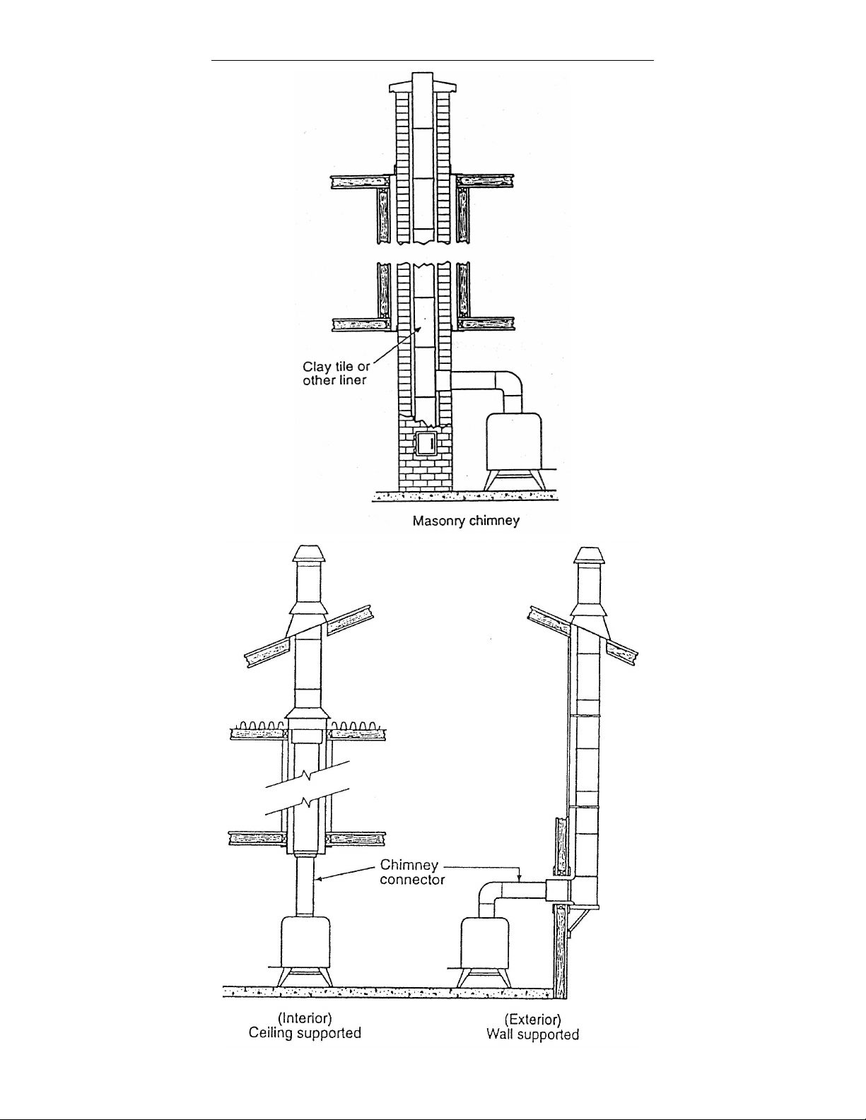
Typical Factory Built or Masonry Chimney Installations
4
Page 5

CHIMNEY CONNECTOR SYSTEMS AND CLEARANCES
FROM COMBUSTIBLE WALLS FOR RESIDENTIAL
HEATING APPLIANCES
A. Minimum 3.5 inch thick brick masonry all fram ed into
combustible wall with a minimum of 12 inch brick
separation from clay liner to combustibles. The fireclay
liner shall run from the outer surface of brick wall to, but
not beyond, the inner surface of chimney flue liner and
shall be firmly cemented in place.
B. Solid-insulated, listed factory-build chimney length of the
same inside diameter as the chimney connector and
having 1 inch or more of insulation with a minimum 9
inch air space between the outer wall of the chimney
length and combustibles.
D. Solid insulated, listed factory-build chim ney length with
an inside diameter 2 inch larger than the chimney
connector and having 1 inch or more of insulation,
serving as a pass-thru for a single wall sheet steel
chimney connector of minimum 24 gauge thickness,
with a m inimum 2 inch air space between the outer wall
of chimney section and combustibles. Minimum length
of chimney section shall be 12 inch chimney section
spaced 1 inch away from connector using sheet steel
support plates on both ends of chimney section.
Opening shall be covered, and chimney section
supported on both sides with sheet steel supports
securely fastened to wall surfaces of minimum 24 gauge
thickness. Fasteners used to secure chimney section
shall not penetrate chimney flue liner.
II. MINIMUM MASONRY FIREPLACE OPENING AND
MINIMUM CLEARANCES TO COMBUSTIBLES
C. Sheet steel chimney connector, minimum 24 gauge
thickness, with a ventilated thimble, minimum 24 gauge
in thickness, having two 1 inch air channels, separated
from combustibles by a minimum of 6 inch of glass fiber
insulation. Opening shall be covered, and thim ble
supported with a sheet steel support, minimum 24
gauge in thickness.
III. FLOOR PROTECTION
In accordance with NFPA 211 guidelines, any com bustible
floor in front of your 4700TEC must be protected with a
non-combustible floor protector equivalent to one layer of
3/8" asbestos millboard.
NOTE: ASBESTOS CANNOT BE USED
Reference to asbestos is used as a standard only, 3/8"
asbestos millboard has a “K” factor of .84. The newer
substitute CERAFORM BOARD has a “K” factor of .21.
Contact your local dealer for off the shelf approved floor
protectors.
5
Page 6

The k, C or R factor that correlates with the floor protector
material used during the test if the room heater is not
provided with a floor protector. The units of measure for k,
C and R factors shall use the sam e applicable units.
Directions and exam ples on how to use alternate materials
and how to calculate equivalent thickness shall be shown.
An easy means of determining if a proposed alternate floor
protector meets requirements listed in the appliance
manual is to follow this procedure:
1. Convent specifications to R-value
a. R-value is given - no conversion is needed.
b. K-factor is given with a required thickness (T) in
inches: R=1/k+T
c. C-factor is given: R=1/C
2. Determine the R-value of the proposed alternate floor
protector.
a. Use the formula in step 1 to convert values not
expressed as “R”.
b. For m ultiple layers, add R-values of each layer to
determine the overall R-value.
3. If the overall R-value of the system is greater than the Rvalue of the specified floor protector, the alternate is
acceptable.
EXAMPLE:
The specified floor protector should be 3/4 inch thick
material with a k-factor of .84.
The proposed alternate is 4" brick with a C-factor of 1.25
over 1/8" mineral board with a k-factor of .29.
Step 1: Use formula above to convert specification to
R-value. R=1/kT = 1/0.84 x .75 = .893
Step 2: Calculate R of proposed system.
4" brick of C - 1.25, therefore
R brick = 1/C = 1/1.25 = 0.80
1/8" mineral board of k+ 0.29, therefore
R min.bd. = 1/0.29 x 0.125 = 0.431
Total R = R brick + R brick + R m ineral Board
= 0.8 + 0.431 = 1.231
Step 3: Compare the proposed system R of 1.231 to
specified R of 0.893. Since proposed system R
is greater than required, this is acceptable.
Definitions:
If your chimney is lined and clean, it must still be measured
to insure that the lliner is not oversized.
For best performance and efficiency, we highly
recommend the following minimums:
Chimney Size: 6" x 6" or 36 sq. in.
Chimney Height: 15 feet and at least 2 feet above the
highest point of your roof.
Draft: .06 w.c.
Measure your fireplace. Your fireplace must be: 29 ½"
wide, 22 ½" high, 15" deep.
Your lintel must be 8" or less. Your hearth must be 9" or
more. You m ust be able to provide 16" of non-com bustible
hearth extension in front of this 9 ½".
Clean out your fireplace and remove screen and glass
doors if present.
Remem ber to have your chimney inspected for leaks and
blockage before you install your stove.
Draft Requirements
Draft is the force which moves air from the appliance up
through the chimney. The amount of draft in your chimney
depends on the size, height and general condition of your
chimney, local geography, nearby obstructions, and other
factors. Inadequate draft will cause the appliance to leak
smoke into the room when starting a fire or adding fuel to
the existing fire. Too much draft m ay cause the stove to
burn too hot and damage the unit.
Minim um Chim ney Requirem ents
Size – 6x6 Height – 15 ft. Draft – .06WC
NOTE: Nine out of ten times, dirty glass, lack of “heating”,
or failure to continue burning after the doors are shut is
evidence of inadequate draft.
V. METHOD I
Method I – This installation uses a direct connection (
direct connect adapter kit) or a section of flexible or rigid
pipe. This connects the stove flue outlet to the first section
of tile liner at the bottom of the chimney. The width of the
damper opening or the throat of the chimney will determine
which type of pipe, rigid, round flexible, or oval flexible,
should be used. Some openings are large enough (6
inches or more) to allow the use of the standard connector
pipe. If the dam per or throat area is narrow, oval flexible
pipe or sheet metal adapter must be used
IV. INSTALLATION INSTRUCTIONS
Your Sierra 4700TEC must be direct connected using
Method I or Method II
Chimney Sizing – Have your chimney cleaned and
inspected by a certified chimney sweep. Chimney MUST
have some type of lining. If your chimney is not lined, you
MUST have your chimney relined.
Relining can be done by either of two methods. Some
dealers reline with a poured masonry mix. Others use
stainless steep pipe wrapped with ceram ic insulation. Both
systems produce excellent results when installed by
competent professionals.
Installation – Method
1. Re move the existing dam per in the fireplace or lock it in
the open position.
2. Determine the type of pipe required for your installation.
3. Cut the pipe to the proper length. 22 inches (approx.
height of flue collar) above the bottom of the fireplace to
at least half way into the first chimney liner.
4. Slide the pipe up through the damper area into the first
chimney liner
5. Measure from the bottom of the fireplace 22 inches.
This should be the bottom of the pipe.
6. Completely pack the damper area or bottom of the first
chimney liner with ceramic wool or other non-
combustible material in a way which no air can go up the
chimney except through the pipe. This is very important,
as it directly affects the chimney draft.
7. Slide the 4700 into the fireplace until the shroud flanges
are approximately 2 inches in front of the face of the
fireplace.
6
Page 7

8. Install the pipe into the flue collar, making sure the pipe
is seated all the way down in the collar.
NOTE: YOU MAY NEED TO REACH UP THROUGH
THE BYPASS MECHANISM TO INSURE PROPER
SEATING.
Be extremely careful to make this connection air tight
with furnace cement, high temperature silicon, or other
high tem perature sealant.
9. Install the shroud and brass trim .
10. Gently slide the 4700TEC the rest of the way into
the fireplace.
11. Level the unit.
12. Double check the seal of the connecting pipe by
reaching through the by-pass opening.
Method I and II – The flue collar of the 4700TEC is an
industry standard 8 inch oval. Most 8 inch oval pipe will fit
into it nicely. Depending on the location, angle, etc., of the
throat or dam per of the fireplace, it may be necessary to
use an adapter. These adapters will allow the pipe to be
connected to the unit at many different angles and be
bolted to the unit in place of being cemented.
VIII. SHROUD INSTALLATION
1. Install the left side by sliding the shroud over the bracket
on the unit and between the front of the side and the
cleat. Align the bottom of the side with the bottom of the
stove.
2. Install right side in the same manner.
3. Install top in the same manner aligning the top shroud
bracket on the stove and tops of both sides.
4. Using a rubber hammer, continue to slide both sides
equal and top on to the brackets until com pletely
seated and each side is straight with the ends on the
top.
5. Install brass trim .
VI. METHO D II
The Method II installation is similar to Method I except that
the connector pipe extends the full length of the chimney
and terminates at the top of the chim ney. Either rigid
round sections or a continuous length of flexible pipe may
be used. This pipe must be constructed of stainless steel
6" diameter minimum. All joints must be secured by at
least 1/8" self-threading sheet m etal screws. Because this
method is usually more difficult and involved, we
recommend that you have a qualified professional installer
do the job for you.
VII. OTHER OPTIONS AND CONSIDERATIONS.
Method I - Depending on the size, shape, or location of the
throat of your fireplace, the ceramic wool installation
cannot be used or will not be acceptable. For those
installations, you m ay need a sheet metal adapter kit.
These kits consist of a piece of sheet metal cut to size to
totally block off the upper portion of the fireplace with a
hole for the pipe to pass through. Consult your local dealer
for more details.
Figure 5
IX. LEVELING THE UNIT
The Sierra 4700TEC is equipped with three leveling bolts,
one behind the ash pan and one on each side behind the
fan covers. The unit should be leveled for proper door
operation and to insure the shroud is aligned with the face
of the fireplace.
----Access the back leveling bolt by removing the ash pan
and ash grate.
----Access the front leveling bolts by removing the fan
covers.
X. FAN COVER REMO VAL
The fan covers of the 4700TEC are held in place with two
spring clips (l each side). The clips have small dimples on
their outer surface that hold them behind the metal body of
the unit. (See Figure 6)
7
Page 8

Figure 6
REMOVAL:
1. Gently pull the edge of the fan cover away from the body
of the unit approx. 1/8"
2. Locate the center of the spring clip.
3. Using a flat screw driver, compress the spring clip.
4. Pull the fan cover out of its opening.
Thermostat – Automatically turns the blowers on when
the unit reaches normal operating temperature and off
when the unit cools below normal operating
temperature.
Automatic/Manual Switch – Allows manual operation of
the blowers before and after thermostat is activated.
NOTE: On low burns (less than .8 Kg/hr.) and medium
burns (.80 to 1.25 Kg/hr.) the room air fan should be
operated on the lowest setting. On high burns (1.90 Kg/hr.
or greater) and m edium high burns (1.25 to 1.90 Kg/hr.)
the blower fans must be operating to avoid excessive heat
build up and possible damage to the fan blades and
electrical components.
Wiring Information
INSTALLATION:
1. Make sure the spring clips are installed in the edge of
the fan cover properly.
2. Center the fan cover over the opening.
3. W ith a flat screw driver, compress the spring while
pushing the fan cover into place.
4. Repeat for the other edge.
XI. ELECTRICAL
Your Sierra 4700TEC is equipped with a 6 ft. power cord,
on/off variable speed control, thermostat and
automatic/manual switch.
On/Off Variable Speed Control
–extreme left –off
–right past click –high
–continuing to the right –high to low
Figure 8
8
Page 9

XII. OPERATING INSTRUCTIONS
For the first few days, the stove will give off an odor and a
small amount of smoke. This happens when the high
temperature paint is bonding to the metal. This is normal
and will stop when the paint is cured, and will reoccur every
time you repaint or touch up your stove.
1. Starting a fire. Crumble three or four full sheets of
newspaper and place them on the flow of your SIERRA
stove.
2. Crisscross two layers of dry kindling on the paper. Add
a few large splits of dry wood on top of the kindling.
3. Make sure the primary air controls are fully open. Also
be sure that the bypass lever is open.
4. Light the paper under the kindling with a match or
lighter. Do not use gasoline, lighter fluid, charcoal
starter, kerosene, or any other such fuel to start a fire in
a woodstove.
5. At higher altitudes, or when starting a fire on a very cold
chimney, it may be necessary to leave the door cracked
open for a few m inutes, no longer than 5 minutes, to
encourage a hot fire.
prevent flashbacks which occur when a very smoky fire
suddenly is given a lot of oxygen.
Every stove chim ney com bination functions a little
differently. Be patient, and expect the stove to be
different in January when it is very cold outside, than it
was in September when the weather was warmer. Once
a chimney is warmed up, its draft is a function of how
muchwarmer it is than the air around it. On m ild fall
evenings, a stove can appear to be finicky and difficult.
However, the very next night, in the midst of a fall storm,
it might act like acompletely different stove.
9. As you burn your stove and wood is consumed, ashes
will fall through the grate and into the ash pan. Also, as
you rearrange your ashes you should work them toward
the ash pan. W hen the ash pan becom es full (this
should be checked daily), pull the ash pan 3/4 of the way
out of the stove. Remove the ashes with a shovel and
place them in a metal container with a tight-fitting lid.
Assum e that there are still hot coals mixed in the. There
usually are for as long as three days.
DO NOT PLACE ASHES WITH THE GARBAGE OR
NEAR ANYTHING COMBUSTIBLE.
THE BEST IDEA IS TO LEAVE THEM OUTSIDE, THREE
FEET AWAY FROM THE HOUSE IN A METAL
CONTAINER FOR THREE DAYS.
NEVER LEAVE YOUR STOVE UNATTENDED WHEN
THE DOOR IS UNLATCHED.
6. W hen the kindling has been consumed and larger splits
are burning well, load the stove to the level you desire,
using well-seasoned, dry wood.
(Wet wood does not heat well.)
DO NOT BURN CO AL IN TH IS UNIT !
Close the doors and continue to burn the stove on high
and with the bypass open until the wood becom es fully
involved. It is not necessary to use additional grates or
irons to support the fuel.
7. Once your chimney and stove are warmed up and
drawing well, close the air inlets to the desired heat
output. Close the bypass before slowing down the air.
Reload when convenient, but always while you still have
a good bed of glowing embers. Always open the bypass
3 minutes before opening the door to reload. Never
close the bypass imm ediately after adding fresh wood to
the fire.
Ashes should be placed in a metal container with a tight
fitting lid. The closed container of ashes should be placed
on a non-combustible floor or on the ground, well away
from all combustible materials, ending final disposal. If the
ashes are disposed of by burial in soil orotherwise locally
dispersed, they should be retained in the closed container
until all cinders have thoroughly cooled. Ash removal doors
must be closed when in operation.
DEFINITION AND PURPO SE OF A CATALYT IC
COMBUSTOR
Catalytic combusto rs for woodstoves (cats ) are sim ilar in
principle to catalytic converters on autom obiles. T he big
difference is that the heat generated by your woodstove
combustor is put to use heating your home instead of
being dum ped out the tailpipe of your car. Catalytic
combustors cause wood smoke to burn at very low
temperatures, releasing energy that would otherwise be
lost in the form of smoke.
As smoke passes through the combustor, a rare metal
coating on the ceramic base of the combustor changes fuel
molecules in the smoke so that they burn at 500 to 600
degrees Fahrenheit, instead of the more normal 1000 to 1200
degrees Fahrenheit. In addition to making stoves burn
cleaner, combustors improve their heating efficiency. On the
average, you will receive 30 to 50% more heat from each
piece of wood, up to 90% less creosote and because the cat
burns most of the smoke, 90% less air pollution than you
would from burning a com parable stove. Of course, results
may be higher or lower depending on the operation, chimney
draft, and combustor age.
Figure 9
8. When opening the door to reload or to poke the fire,
open the bypass first. Crack the door and hesitate just a
few seconds before swinging it open. All this is to
OPERATION
Achieving catalytic light off. During each burning cycle, the
temperature within the stove should be raised high enough
to cause the catalyst to become active or “light off.” The
most convenient w ay to do this is during fuel loading while
warming up the wood and the chimney. With a new
combustor, smoke temperatures between 500 and 600
degrees (F) will begin catalytic burning. (Since the
com bustors sit right above a roaring fire, this is not hard to
9
Page 10

achieve if you follow the instructions in Starting a Fire and
Operating Your Stove.) As a combustor ages, its catalytic
activity decreases, so an older cat (beyond three years old)
needs m ore heata during the start-up. 700 degrees will
generally be sufficient for light off even on an old
combustor.
Your SIERRA Ambassador Insert has an option from your
dealer, a catalytic indicator which will take the guesswork
out of knowing when you have light-off.
W henever the stove is being loaded,
KEEP THE BYPASS OPEN.
Once or twice a season, remove the mixer plates and
lightly brush the face of the com bustors to rem ove any fly
ash which may have been sucked in by the chim ney draft.
Remember, the combustors and mixers can stay hot for a
long time after the last fire. Always use gloves. NEVER
remove the combustors to clean them. You will break the
seal around the combustor which will allow smoke leakage
and reduce the efficiency of the catalyst.
MAINTAINING CATALYTIC CONDITIONS:
During the start-up of a cold stove, a medium to high air
setting must be m aintained for amout 20 minutes to ensure
that the stove, catalyst, fuel, and chimney are all at proper
operating temperatures. Even though it is possible to have
smoke temperatures reach 600 degrees within two or three
minutes after a fire is started, the combustor and the
chimney are not yet warm enough.
At the end of the burn cycle, it’s possible that the amount of
burning charcoal might not provide sufficient temperatures
for the catalyst. During the refueling, we recommend that
the stove be fired hard for at least 10 minutes to ensure the
catalyst and chimney are properly warmed up. If you have
an extra long or large diamenter chimney, or if it is very
cold outside, run the stove on high for a longer period.
BURN UNTREATED WOOD ONLY, OTHER MATERIALS
SUCH AS WOOD PRESERVATIVES, METAL FOILS,
COAL, PLASTIC, GARBAGE, SULPHUR OR OIL MAY
DAMAGE THE CATALYST.
WARNING – OPERATE ONLY WITH DOORS FULLY
OPEN OR FULLY CLOSED. IF DOORS ARE LEFT
PARTLY OPEN, GAS AND FLAME MAY BE DRAWN
OUT OF THE OPENING CREATING RISKS FROM BOTH
FIRE AND SMOKE.
XIII. COMBUSTOR LIFE AND REPLACEMENT
SIERRA uses only “12,000 hour long-life combustors.” The
com bustor will still be functioning at 70% of its
effectiveness after 12,000 hours of use. Depending on the
frequency of stove use, it will last for four to twelve years
before needing replacem ent. If you find your com bustor is
not igniting, finish the burn cycle you have begun. You may
order replacement catalytic combustors from your SIERRA
dealer.
CATALYTIC WARRANTY
10
Page 11

Refer to the catalytic combustor manufacturer’s warranty
card which is packaged with the combustor.
REMOVAL FOR INSPECTION OR REPLACEMENT OF
CATALYTIC COMBUSTORS
1. Combustor assembly is accessed through stove door
opening. Using 3/8" socket, remove the two nuts (one on
each side) that holds heat shield and mixer plates.
Remove assembly through stove door. (See figure 10)
2. After removing mixer plate, use an extended socket to
loosen nuts on catalytic assembly base (one on either
side). Remove nuts and slide catalytic base assembly out
through front of unit and through stove door opening.
3. Catalytic combustors can no be inspected. If combustors
are rem oved from the holders, check condition of inter rim
gasket m aterial around the combusto rs and replace if
necessary.
4. To reassemble, ensure combustors are properly seated
in combustor holder and that the inter rim gasket is in good
condition. To complete assembly, reverse steps 1 and 2.
TO INSPECT OR REPLACE BYPASS DAMPER GASKET
For top efficiency and low emissions the bypass must be
sealed. Bypass gasket may be checked by putting a light
inside of stove (inside of fire box), looking in through flue
opening on top of stove, check for light leakage.
Should gasket need replacing, it can be accessed through
stove door. Lift old gasket up out of channel, clean
channel, re-glue, and press new gasket into place.
This is done with damper in open position.
TO REPLACE DAMPER ROD (See Fig. 12)
Reaching in through stove door, use a 5/16" open end
wrench to loosen lock nut at end of rod (against yoke).
After backing lock nut away from yoke, rod may be
unscrewed by turning counter clockwise from front of
stove. After rod is loose from yoke, remove lock nut from
rod and pull rod out.
Insert new rod through opening in front of stove, screw lock
nut onto rod, align with weld nut in yoke and turn clockwise
to tighten. When tight, run lock nut against yoke and
tighten securely.
XIV. STOVE AND CHIMNEY MAINTENANCE
CHIMNEY AND CREOSOTE
Creosote is one of the facts of life for wood burners. When
wood is burned slowly, it produces tar and oth er organic
vapor which combines with expelled moisture (even “dry”
wood contains approximately 20% moisture) to form
creosote. The creosote vapors condense in the relatively cool
chimney connectors and flue of a slow-burning fire. As a
result, creosote residue accumulates on the flue lining. Large
amounts of this tough, gummy, tar-like substance can pile up
quickly and virtually choke a stove pipe. W hen ignited, this
creosote makes an extremely hot and dangerous fire.
Be sure to examine the chimney connector pipe and the
chimney above it every few weeks so you can determine
the rate of creosote build up. Any excessive build up of
creosote (more than 1/4") will then be apparent and must
be removed for continued safe operation.
The chimney must be inspected from the top of the
chimney. For a thorough cleaning and inspection, your
SIERRA woodstove should be removed from the hearth.
If creosote has accumulated, it should be removed to
reduce the risk of a chimney fire. Creosote formations can
be chipped away from flue openings with a sturdy metal
blade such as a heavy duty scraper. C AUTIO N : The acid
content can cause burns to skin and eyes, so wear
protective glasses and gloves. T he chim ney itself is
normally cleaned from the roof. Most stove dealers carry
stiff metal brushes in sized and shapes to fit standard flue
liners. These are usually attached to rods which can be
extended for the length of the chimney. It is recommended
that you call a professional chimney cleaner to do the job
for you.
If any deterioration or damaged areas are found during
routine cleaning and inspection, consult a skilled chimney
sweep or brick mason for advice. Any repairs needed
should be com pleted before operating unit.
11
Page 12

STOVE MAINTENANCE
CARE AND CLEANING OF WOODSTOVE GLASS
At the end of each season, thoroughly clean the inside of
the firebox area including the area under the grate and ash
drawer. Vacuum all air passageways and the fan cover
screens. Check the door and window gaskets and replace
if necessary. Replace any broken bricks on the firebox
bottom. The external surface may be lightly sanded and
repainted with SIERRA high temperature stove paint,
available from your local dealer, whenever necessary.
(Make sure stove is cool.)
CLEANING THE GLASS
Your SIERRA woodstove is designed so that the glass
stays clean from normal usage. The hotter the fire and the
closer the fire is to the glass, the cleaner the glass will stay.
If your glass does become dirty, you can clean it with a
damp cloth, after the stove has cooled down. For
particularly hard to remove buildup you may use a razor
blade. Be very careful not to scratch the glass.
The glass may becom e dirty on ;your 4700 during the startup period. If this occurs, simply open the bypass
damper:then, after a minute or so, slowly open the loading
door. Gently scrape the glass clean of build-up and reclose
the door. At this point the glass will stay clean if a high
temperature level is maintained.
Inspect the glass regularly for cracks or breaks. If you find
a crack or break, replace your glass im m ediately, as air
can enter the firebox through the crack and you will not be
able to control your fire. See your SIERRA dealer for
replacement glass.
The window glass on your SIERRA woodstove is designed
for high temperature performance and will withstand
normal woodstove temperatures. However, like most glass,
it will break if struck with sufficient force. So be careful
when loading wood. You may break your glass by jamming
a lot of wood against it, or by attem pting to push a log into
the fire with the stove door. Never load your SIERRA stove
with materials which could ignite explosively; even sm all
explosions in a small airtight stove may blow out the glass.
Always use the fiberglass window gasket supplied with the
replacement glass.
Replace the door gaskets on your SIERRA stove every two
to three seasons. Replace the window gaskets only if you
need to replace the glass. See your SIERRA dealer for
SIERRA replacement parts.
BLOWER MAINTENANCE
Regularly check the fan covers for dust buildup and
remove any present. Also be sure to check the power cord
for any signs of wear or damage. Have the cord replaced
by a qualified electrician if necessary.
By following the manufacturer’s recommendations your
Sierra Stove will give you years of service
CONSUMER PROTECTION WARRANTY
Your Sierra Stove has a Lim ited Five-Year W arranty.
Please read it carefully, fill out the short registration form
and return it, within 30 days of purchase, to
Sierra Products, Inc., 5061 Brooks St. Ste. B
Montclair, CA 91763.
Sierra Products, Inc.
5061 Brooks St., Ste B
Montclair, CA 91763
(909) 399-3355
12
Page 13

Sierra Ambassador Model 4700TEC Parts List
13
P/N 140820 4700TEC MANUAL r1
 Loading...