

Page 1
Operation and Installation Instructions
MODEL ZS-30
Intrinsically Safe Module
Fire Safety
Operation
The SIEMENS System 3 Intrinsically Safe Zone Model
ZS-30, consisting of a Zone Module and a Diode
Shunt Barrier, is designed for use in System 3 low
voltage control panels. With detection devices located
in hazardous areas identified as Class I, II, and III,
Division 1, Groups A, B, C, D, E, F, and G, the intrinsically safe characteristic is achieved by using a diode
shunt barrier (P/N 515-180238) with the ZS-30. The
Diode Shunt Barrier, though physically a separate unit
of ZS-30, must always be used to achieve an intrinsically safe zone. The Diode Shunt Barrier limits the
energy to the detector circuit.
The following equipment is covered by this instruction
sheet.
Item Name and
Model Number Description
NON-HAZARDOUS LOCATION EQUIPMENT
Model ZS-30 Zone module (P/N 515-022079)
Model 515-180238 Diode shunt safety barrier
(P/N 515-180238)
HAZARDOUS LOCATION EQUIPMENT
Detector DI-3IS
Detector S121
Detector S122
Base DB-3 For use with DI-3IS
Cable 465-514391 Limited-energy shielded cable
(Optional)
Check that each device to be located in the intrinsically safe area has an FM intrinsically safe label. In
addition, direct shorting manual stations and/or
thermal detectors (devices not containing any energy
storing, or voltage producing, components) may be
connected in the detector loop without jeopardizing the
intrinsically safe characteristics of the system.
NEC Hazardous Location Classification
Class I: Class I locations are those in which flammable
gases or vapors are (or may be) present in the air in
quantities sufficient to produce explosive or ignitable
mixtures.
Class II: Class II locations are those that are hazardous
because of the presence of combustible dust.
Class Ill: Class Ill locations are those that are hazardous
because of the presence of easily ignitable fibers or
flyings, but in which such fibers or flyings are not likely
to be in suspension in the air in quantities sufficient to
produce ignitable mixtures.
Division 1: A Division 1 location is a location (a) in
which hazardous concentrations of flammable gases or
vapors exist continuously, intermittently, or periodically
under normal operating conditions; or (b) hazardous
concentrations of such gases or vapors may exist
frequently because of repair or maintenance operations
or because of leakage; or (c) breakdown or faulty
operation of equipment or processes that might release
hazardous concentrations of flammable gases or vapors
occur and might also cause simultaneous failure of
electric equipment.
Group A: Group A atmospheres contain acetylene.
Group B: Group B atmospheres contain such chemi-
cals as butadiene, hydrogen ethylene oxide
(or gases or vapors of equivalent hazard to
hydrogen, such as manufactured gas), or
propylene oxide.
Group C: Group C atmospheres contain such chemicals
as acetaldehyde, cyclopropane, diethyl
ether, ethylene, isoprene, or unsymmetrical
dimethyl hydrazine (UDMH).
Group D: Group D atmospheres contain such chemicals
as acetone, acrylonitrile, alcohols, ammonia,
Siemens Building Technologies, Inc.
8 Fernwood Road
Florham Park, New Jersey 07932
P/N 315-024056-17
Siemens Building Technologies, Ltd.
2 Kenview Boulevard
Brampton, Ontario L6T 5E4 CN
Page 2
benzine, benzol, butane, ethylene dichloride, gasoline, hexane, lacquer solvent
vapors, naphtha, natural gas, propane,
propylene, styrene, vinyl acetate, vinyl
chloride, or xylenes.
Group E: Atmospheres containing combustible metal
dusts regardless of resistivity, or other
combustible dusts of similarly hazardous
characteristics having resistivity of less than
105 ohm/centimeter.
Group F: Atmospheres containing carbon black,
charcoal, coal, or coke dusts which have
more than 8 percent total.
Group G: Atmospheres containing combustible dusts
having resistivity of 105 ohm/centimeter or
greater.
Description
The heat and smoke actuated detectors are located
in a hazardous location. A Class B two wire detector
circuit extends back to the non-hazardous location
where connections are made to terminals 5 (output
ground) and 1 (output) of the Diode Shunt Barrier
located in the system control panel cabinet (or in a
separate enclosure). Under normal operating conditions voltage and current in the hazardous locations
are at levels known to be safe for intrinsically safe
electrical equipment operating in Group A atmospheres. However, should any combination of two
independent faults occur (plus field wiring failures)
within the system, the barrier will prevent the appearance of excessive voltage and currents in the hazardous location. The ZS-30 module is part of a low
voltage control panel and is connected to the barrier
and detector circuit. The module is mounted on a
System 3 panel along with the control unit. The
intrinsically safe module is interconnected to System 3
modules bus wire cable and draws its power from the
System 3 power supply through the control unit. The
module provides regulated voltage to the detectors in
the hazardous locations through the Diode Shunt
Barrier. It also detects and generates trouble and
alarm conditions. Alarm and trouble conditions are
indicated by red and yellow LEDs on the panel on the
intrinsically safe zone, and corresponding high-going
electronic signals are passed to the control unit. The
detector circuit consists of up to ten DI-3IS ionizationtype smoke detectors or up to five S121 or S122 flame
detectors, in addition to any number of mechanical
(non-energy storing) shorting devices. The detector
circuit is terminated by a 5.6K ohm end of line resistor.
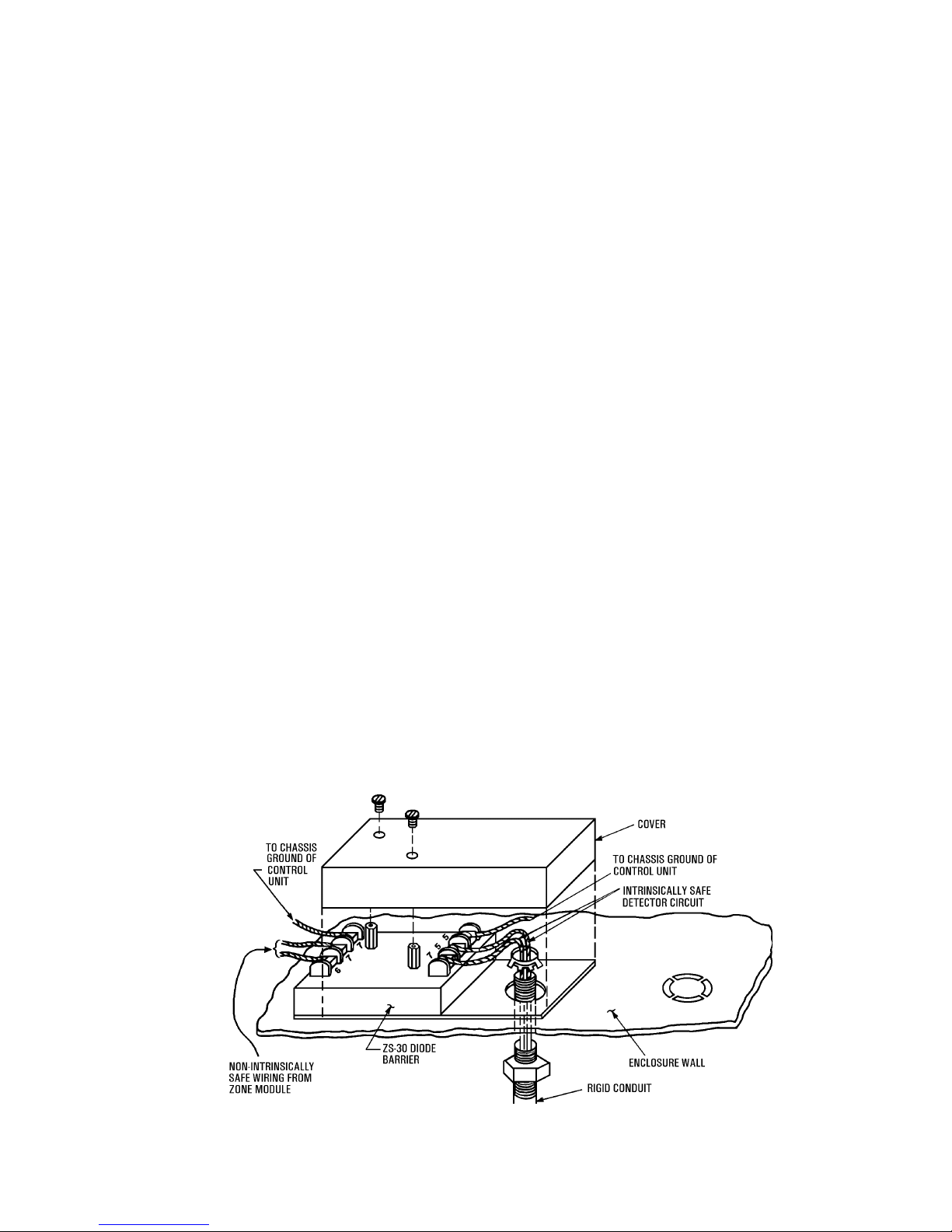
Installation
Refer to Figures 1-3 below when installing the ZS-30.
The Diode Barrier may be located in the main control
panel or in a separate enclosure; but, in either case,
care must be exercised in installation.
System 3 chassis ground must be removed. Each
duplicate (redundant) grounding conductor should be
connected to the grounding connections on the barrier
device and run directly to the ground electrode not
via other paths leading to that electrode.
Each ground wire must be 14 or 18 AWG wire and
should not exceed an impedance of 1 ohm. All ground
wires should be connected separately to the same
ground location. Wiring connected to the barrier output
Figure 1
Field Assembly of Diode Barrier
2
Page 3

(terminals 1 and 5) must be grouped with intrinsically
safe circuits and must not run in conduits and wireways containing non-intrinsically safe circuits.
Wiring from the control unit enclosure or separate
diode barrier enclosure to the intrinsically safe zone
must be rigid conduit, and the conduit should be sealed
off from the hazardous area at the barrier wall by using
standard EY conduit seals to isolate the hazardous
atmosphere from the control equipment. Chico X fiber
and Chico A sealing compound must be used to make
the seal. Wiring in the hazardous area may be either
limited energy shielded cable (Siemens Building
Technologies, Inc. P/N 465-514391) or any type of
general purpose wire. The diode barrier may be
located either in the control unit enclosure or in its own
enclosure. Proper assembly and conduit are essential;
follow Figure 1.
Non-energy storing devices such as a manual station
may be connected in the detector loop without jeopar-
dizing the intrinsically safe characteristics of the
system. Such devices must be connected in parallel
with the barrier output, must not contain any energy
storing component(s), and must be operationally
approved by Factory Mutual for the intended purpose.
Maximum detector loop resistance must not exceed
50 ohms, exclusive of the 5.6K ohm end of line resistor.
The maximum inductance and capacitance for cables
or wires connected to the barrier output should not
exceed the following values for each group.
Maximum Maximum Capacitance
Inductance Excluding Detector
in mH Capacitance in µF
Group A 20 .1
Group B 20 .1
Group C,E,F 80 .3
Group D,G 150 .8
Note: FM Control Document there are to be no changes to this document without prior Factory Mutual approval.
Figure 2
Barrier Label
3
Page 4

NOTES:
1. TROUBLE AND ALARM OUTPUT:
OPEN CIRCUIT VOLTAGE 22 VDC
SHORT CIRCUIT CURRENT 30 mA
2. WHEN ZS-30 IS USED, SYSTEM CHASSIS GROUND CONNECTION MUST BE
REMOVED AND TERMINALS 5 AND 7 OF DIODE SHUNT BARRIER MUST BE
INDEPENDENTLY CONNECTED TO CHASSIS GROUND.
3. MAXIMUM LOOP RESISTANCE MUST NOT EXCEED 50 OHMS.
4. A MAXIMUM OF TEN DI-3IS IONIZATION DETECTORS OR UP TO
FIVE S121 OR S122 FLAME DETECTORS CAN BE USED IN ADDITION TO
MECHANICAL (NON-ENERGY STORING) SHORTING DEVICES.
5. MAXIMUM SAFE SYSTEM VOLTAGE IS 250 VAC.
P/N 315-024056-17
6. REFER TO TEXT FOR LIMITATIONS AND DEFINITION OF THE HAZARDOUS
AREA.
7. ONLY MECHANICAL (NON-ENERGY STORING) SHORTING DEVICES SUCH AS
THE MS-51 MANUAL STATION MAY BE USED.
8. WARNING: DO NOT MAKE ANY CONNECTION TO TERMINAL 6 OF THE DI-3IS
BASE. SUCH A CONNECTION WOULD VOID USE IN AN INTRINSICALLY SAFE
APPLICATION.
9. IN ADDITION, S121 AND S122 ARE ALSO APPROVED FOR USE IN CLASS II
AND CLASS III, GROUPS E, F, AND G.
Figure 3
Wiring Diagram
ZS-30 Intrinsically Safe Zone
 Loading...