

Siemens ZN-34US, ZN-34UA Installation Instructions Manual

Installation Instructions
Models ZN-34US and ZN-34UA
Gate Valve Supervision Modules
Description
The Sprinkler Valve Supervision Modules, Model ZN34US and Model ZN-34UA, are designed to provide
two circuits for the supervision of sprinkler system
gate valves and ancillary equipment in accordance
with NFPA Standard 72. The module provides two
yellow LED indicators per circuit. The first illuminates
when a supervisory condition exists and the second
when a circuit trouble condition occurs. The module
utilizes an end-of-line resistor in parallel with normally
open switches to provide this supervision.
The Model ZN-34US provides annunciation of conditions as follows; when a sprinkler valve is closed the
supervisory circuit is shorted, the yellow supervisory
LED is illuminated and the supervisory module output
is energized. The output should be used to operate a
separate AE-30U Module with an audible device.
When a break in the circuit occurs the module trouble
LED is illuminated and the control panel is placed in
system trouble. The supervisory condition is nonlatching, therefore, the supervisory condition will
clear if the sprinkler valve is restored to its normal,
open position.
The Model ZN-34UA is a latching device. Operation
is the same as the ZN-34US except that the condition
latches and can only be cleared through a system reset after the sprinkler valve is restored to its normal,
open position.
In addition to gate valves, other sprinkler supervisory
limit functions such as water pressure, water level,
temperature, air pressure and fire pump supervision
may be supervised with the ZN-34US/-UA.
All module LEDs are illuminated when the system reset/lamp test switch on the CP-35 main module is operated. The ZN-34US/-UA sprinkler valve supervision
module is placement supervised, providing a system
trouble signal upon removal from the system.
2. Install the Model JA-5 (5 in long) bus connector
cable assembly between receptacle P2 of the
module and receptacle P1 of the module or
control panel immediately preceding it in the bus.
Note: If the preceding module is on another row
in the enclosure, a JA-24 (24 in long) bus
connector cable assembly will be required.
3. Modules are to be bus-connected from right to
left. For two-row enclosures, the modules in the
lower row are to be connected from left to right.
Succeeding rows are to be alternately
connected, right to left, left to right, etc.
4. If a module is the last module in the system,
install either a JS-30 (30 in long) or JS-64 (64 in
long) bus connector assembly from the unused
receptacle of the last module to terminal 41 of
the CP-35 control panel. This completes the
module supervision circuit.
5. Wire the circuit(s) as described in the CP-35
Control Panel Instruction Manual (P/N 315-
085063) Installation and Wiring. Refer to the Wiring
illustration.
Note: If a zone is not used, the EOL device
should be connected to the alarm initiating circuit
terminals 2 and 3 (Zone 1) or 4 and 5 (Zone 2) of
the module.
6. If a supplementary relay module, annunciator, or
other output module is used, then the alarm
outputs, terminals 1 (Zone 1) and 6 (Zone 2),
should be connected to these units.
Wiring Test
Refer to the CP-35 Control Panel Instruction Manual,
Installation and Wiring.
Electrical Information
Installation
1. Mount the module to the horizontal mounting
brackets in the control enclosure.
Siemens Industry, Inc.
Building Technologies Division
Florham Park, NJ
P/N 315-094221-10
21.5 VDC at 18mA Supervision and 100mA Supervisory Switch Activated
Maximum loop resistance: 100 ohms
Siemens Building Technologies, Ltd.
Fire Safety & Security Products
2 Kenview Boulevard
Brampton, Ontario
L6T 5E4 Canada
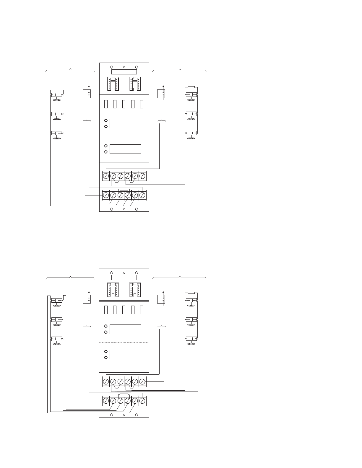
Typical Wiring Diagram
ZN-34US
ZONE 1
TO AE-30U
SM-30
OPTIONAL
SILENCE
UNSUPERVISED
OUTPUT RATED
UNFILTERED FULL
WAVE RECTIFIED
(SEE NOTE 1)
(SEE NOTE 2)
(SEE NOTE 3)
24 VDC, 15mA
STYLE E
CLASS A SUPERVISION
+
-
SUPERVISED INITIATING CIRCUIT
21.5 VDC at 18mA SUPERVISON and
100mA SUPERVISORY SWITCHACTIVATED
UNFILTERED FULL WAVE RECTIFIED
P1
)
TED
N
A
PER
O
STATIO
T
AL
AC
TR
NT
O
EN
C
YC
R
A72
TED
VISO
A
NFP
R
R
78910
PER
(FO
O
SUPE
UBLE
O
TR
123456
*
5.6K OHMS, 1/2W, P/N 140-049898
ZN-34US
SUPERVISORY
TROUBLE
ZONE 1
ZONE 2
SUPERVISORY
TROUBLE
11
EOL
*
EOL DEVICE EL-31 USED
WITH EOL ASSEMBLY,
ZONE 2
P2
TO AE-30U
(SEE NOTE 3)
UNSUPERVISED
OUTPUT RATED
24 VDC, 15mA
UNFILTERED FULL
WAVE RECTIFIED
12
21.5 VDC at 18mA SUPERVISON and
100mA SUPERVISORY SWITCHACTIVATED
UNFILTERED FULL WAVE RECTIFIED
WITH EOL ASSEMBLY 5.6K OHMS,
SM-30
OPTIONAL
SILENCE
(SEE NOTE 1)
TED
N)
A
PER
TED
O
STATIO
T
AL
AC
PERA
T
O
N
CENTR
BLE
YCO
U
R
A72
TRO
VISO
NFP
R
R
PE
(FO
SU
(SEE NOTE 2)
SUPERVISED INITIATING CIRCUIT
CLASS B SUPERVISION
EOL DEVICE EL-31 USED
1/2W, P/N 140-049898
EOL
+
-
NOTES:
1. Normally open parallel connected gate
valve contacts, or the equivalent.
2. The maximum loop resistance for
each zone is 100 ohms.
3. Connect the supervisory contact
operated output of the zone (terminal
6 or 12) to the input of a dedicated
AE-30U (terminal 5 or 6). Multiple ZN34US zones may be connected to a
single AE-30U. Refer to the CP-35
Wiring Information, P/N 315-085178,
for signal factor load units.
4. The ZN-34US is a non-latching device
and follows NFPA 72 guidelines for
operation.
5. Minimum wire size: 18 AWG
Maximum wire size: 12 AWG
6. Positive and negative ground fault
impedance threshold ≤ 40K ohms.
7. TB positions 1-12 are power limited.
Typical Wiring Diagram
ZN-34UA
ZONE 1
TO AE-30U
SM-30
OPTIONAL
SILENCE
UNSUPERVISED
OUTPUT RATED
24 VDC, 15mA
UNFILTERED FULL
WAVE RECTIFIED
(SEE NOTE 1)
(SEE NOTE 2)
(SEE NOTE 3)
CLASS A SUPERVISION
+
-
SUPERVISED INITIATING CIRCUIT
21.5 VDC at 18mA SUPERVISON and
100mA SUPERVISORY SWITCHACTIVATED
UNFILTERED FULL WAVE RECTIFIED
)
TED
N
A
PER
O
STATIO
T
AC
TRAL
NT
O
EN
C
YC
R
A72
TED
A
NFP
R
PER
(FO
O
SUPERVISO
BLE
U
TRO
ZN-34UA
P1
SUPERVISORY
TROUBLE
ZONE 1
ZONE 2
SUPERVISORY
TROUBLE
78910
11
EOL
*
123456
EOL DEVICE EL-31 USED
*
WITH EOL ASSEMBLY,
5.6K OHMS, 1/2W, P/N 140-049898
ZONE 2
P2
TO AE-30U
(SEE NOTE 3)
UNSUPERVISED
OUTPUT RATED
UNFILTERED FULL
WAVE RECTIFIED
12
21.5 VDC at 18mA SUPERVISON and
100mA SUPERVISORY SWITCHACTIVATED
UNFILTERED FULL WAVE RECTIFIED
WITH EOL ASSEMBLY 5.6K OHMS,
SM-30
OPTIONAL
SILENCE
24 VDC, 15mA
(SEE NOTE 1)
)
TED
N
A
PER
TED
STATIO
ACT O
PERA
O
NT
ENTRAL
C
BLE
U
A72
TRO
FP
N
R
UPERVISORYCO
(FO
S
(SEE NOTE 2)
SUPERVISED INITIATING CIRCUIT
CLASS B SUPERVISION
EOL DEVICE EL-31 USED
1/2W, P/N 140-049898
EOL
+
-
NOTES:
1. Normally open parallel connected gate
valve contacts, or the equivalent.
2. The maximum loop resistance for each
zone is 100 ohms.
3. Connect the supervisory contact
operated output of the zone (terminal 6
or 12) to the input of a dedicated
AE-30U (terminal 5 or 6). Multiple ZN34UA zones may be connected to a
single AE-30U. Refer to the CP-35
Wiring Information, P/N 315-085178,
for signal factor load units.
4. The ZN-34UA is a latching device and
follows ULC S527 requirements.
5. Minimum wire size: 18 AWG
Maximum wire size: 12 AWG
6. Positive and negative ground fault
impedance threshold ≤ 40K ohms.
7. TB positions 1-12 are power limited.
P/N 315-094221-10
 Loading...