

Page 1
HNET/CAN
Installation Instruct ions
Model ZIC-8B
Zone Indicating Card
INTRODUCTION The Model ZIC-8B from Siemens Industry, Inc., is a zone
indicating card that provides notification appliance circuits for
the FireFinder-XLS/Desigo Fire Safety Modular/Cerberus PRO
Modular system. It has 8 outputs that can be configured as
Class B only for control of audible and visual notification
appliances such as horns, speakers, bells, strobes, etc.
Each zone can be configured independently for different
usages as programmed in the Zeus tool and can be controlled
automatically by program logic or manually using the PMI/
PMI-2/PMI-3 (XLS), FCM2041-U2 (Desigo Fire Safety Modular), FCM2041-U3 (Cerberus PRO Modular). Installation of a
ZIC-2C Zone Indicating Card on the ZIC-8B gives it two
channel audio capability.
The ZIC-8B supports synchronized and non-synchronized
strobes. This selection is available in the Zeus tool under the
detail properties for each ZIC-8B circuit. Synchronization across
multiple ZIC-8B cards is automatic as a part of the FireFinderXLS/Desigo Fire Safety Modular/Cerberus PRO Modular
operating characteristics. Refer to document P/N 315-096363
for a list of strobes that support synchronization.
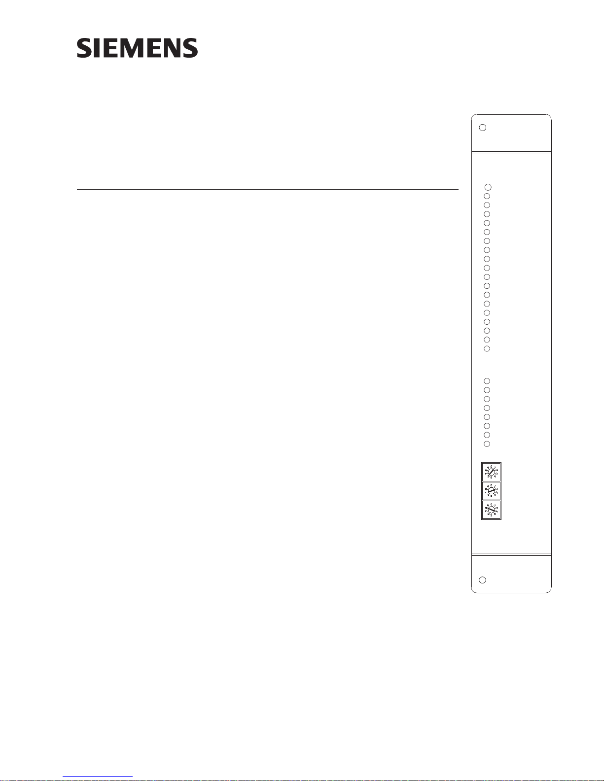
ZIC-8B
RESET
POWER
CARD FAIL
CAN FAIL
HNET FAIL
GND FAULT
ZONE 1 ACTIVE
TRBL
ZONE 2 ACTIVE
TRBL
ZONE 3 ACTIVE
TRBL
ZONE 4 ACTIVE
TRBL
ZONE 5 ACTIVE
TRBL
ZONE 6 ACTIVE
TRBL
ZONE 7 ACTIVE
TRBL
ZONE 8 ACTIVE
TRBL
HUNDREDS
Features ZIC-8B features are as follows:
• Class B circuit configuration
• Zones can be configured independently
• Can have independent input source for
• Zone input voltage supervision per input (DC only)
• Zone output supervision
• Intelligent self-restoring power limiting
• Coded signal synchronization capability
• Card level Ground Fault detection
• Communicate H-Net protocol
• Uploadable firmware update
• Ability to pass through up to 2A per output circuit
P/N 315-048670-11
(See Note on Restrictions, page 2)
every 2 outputs
Building Building
Building
Building Building
TENS
ONES
Figure 1
ZIC-8B Zone Indicating Card
Siemens Siemens
Siemens
Siemens Siemens
TT
ecec
hnologies Dihnologies Di
T
ec
hnologies Di
TT
ecec
hnologies Dihnologies Di
IndustryIndustry
Industry
IndustryIndustry
visionvision
vision
visionvision
,,
Inc. Inc.
,
Inc.
,,
Inc. Inc.
Page 2

RESTRICTIONS
Each zone input supplies power to two adjacent zone outputs as follows:
Zone Input Zone Output
1 1 and 2
2 3 and 4
3 5 and 6
4 7 and 8
Adjacent associated output zones must have the same usage. Each output must not
draw greater than 2A@24 VDC. During system test be sure to activate each zone
output pair to ensure that the maximum zone input current is not exceeded.
When any of the ZIC-8B output circuits are used for speakers the following rules apply:
1. The output circuits are available in two groups, 1-4 and 5-8.
2. Either output group can be used for speakers or NACs.
3. Each output circuit in an output group must have the same usage.
4. Unused output circuits must not be configured in Zeus.
5. Zone inputs 1-2 feed output circuits 1-4.
6. Zone inputs 3-4 feed output circuits 5-8.
OPERATION The ZIC-8B contains eight Class B circuits. Each circuit is rated at 2A at 24VDC and
has an input connected to the power source and an output where the NAC devices
are connected. The zone inputs are isolated from one another and are supervised for
the presence of power. This allows the use of different power sources with different
ground references. The zone output is supervised for open and short circuit conditions while the zone is inactive and allows different combinations of output configurations (standard NAC, speakers, etc.) per card. Each ZIC-8B card occupies any one
card slot in the CC-5/CC-2 cardcage. The ZIC-8B also has the capability to detect
ground fault on its zone output as indicated by a diagnostic LED. (See Note above.)
Controls and Indicators The front panel of the ZIC-8B contains one reset switch, twenty-one LEDs, and three
HNET address switches as shown in Figure 1.
A reset switch is located on the top of the front panel. Pushing the reset switch
re-initializes the ZIC-8B operation.
The LEDs follow the reset switch and their functions are defined as follows:
POWER (Green) Normally ON. When illuminated, indi-
cates that power for the ZIC-8B is
applied to the card.
CARD FAIL (Yellow) Normally OFF. When illuminated, indicates
that the card microprocessor has failed.
CAN FAIL (Yellow) Normally OFF. When illuminated, indicates
that the CAN communication with the
ZIC-8B has terminated and the card goes
into degrade mode (applicable only when
card resides in a CAN network). NOT USED
for FireFinder-XLS/Desigo Fire Safety
Modular/Cerberus PRO Modular
applications.
HNET FAIL (Yellow) Normally OFF. When illuminated, indi-
cates that the HNET communication with
the ZIC-8B has terminated and the card
goes into degrade mode (applicable only
when card resides in the HNET network).
Siemens Industry, Inc.
Building Technologies Division
P/N 315-048670-112
Page 3

GND FAULT (Yellow) Normally OFF. When illuminated, indi-
cates that the ZIC-8B has detected either
a negative or positive ground fault on its
field wiring.
ZONE 1 ACTIVE (Red) Normally OFF. When illuminated, indi-
cates that Zone 1 is active.
TROUBLE (Yellow) Normally OFF. When illuminated, indi-
cates that the ZIC-8B has detected a
trouble on Zone 1 (open circuit or short
circuit) or Zone 1 is disarmed.
ZONE 2 ACTIVE (Red) Normally OFF. When illuminated, indi-
cates that Zone 2 is active.
TROUBLE (Yellow) Normally OFF. When illuminated, indi-
cates that the ZIC-8B has detected a
trouble on Zone 2 (open circuit or short
circuit) or Zone 2 is disarmed.
ZONE 3 ACTIVE (Red) Normally OFF. When illuminated, indi-
cates that Zone 3 is active.
TROUBLE (Yellow) Normally OFF. When illuminated, indi-
cates that the ZIC-8B has detected a
trouble on Zone 3 (open circuit or short
circuit) or Zone 3 is disarmed.
ZONE 4 ACTIVE (Red) Normally OFF. When illuminated, indi-
cates that Zone 4 is active.
TROUBLE (Yellow) Normally OFF. When illuminated, indi-
cates that the ZIC-8B has detected a
trouble on Zone 4 (open circuit or short
circuit) or Zone 4 is disarmed.
ZONE 5 ACTIVE (Red) Normally OFF. When illuminated, indi-
cates that Zone 5 is active.
TROUBLE (Yellow) Normally OFF. When illuminated, indi-
cates that the ZIC-8B has detected a
trouble on Zone 5 (open circuit or short
circuit) or Zone 5 is disarmed.
ZONE 6 ACTIVE (Red) Normally OFF. When illuminated, indi-
cates that Zone 6 is active.
TROUBLE (Yellow) Normally OFF. When illuminated, indi-
cates that the ZIC-8B has detected a
trouble on Zone 6 (open circuit or short
circuit) or Zone 6 is disarmed.
ZONE 7 ACTIVE (Red) Normally OFF. When illuminated, indi-
cates that Zone 7 is active.
TROUBLE (Yellow) Normally OFF. When illuminated, indi-
Siemens Industry, Inc.
Building Te chnologies Division
cates that the ZIC-8B has detected a
trouble on Zone 7 (open circuit or short
circuit) or Zone 7 is disarmed.
P/N 315-048670-113
Page 4

ZONE 8 ACTIVE (Red) Normally OFF. When illuminated, indi-
cates that Zone 8 is active.
TROUBLE (Yellow) Normally OFF. When illuminated, indi-
cates that the ZIC-8B has detected a
trouble on Zone 8 (open circuit or short
circuit) or Zone 8 is disarmed.
Three rotary dial switches at the bottom of the front panel are used to set the HNET
network address of the ZIC-8B.
Output Zones The ZIC-8B output zones can be configured as 25V or 70V speaker zones or for the
following standard NAC Zone usages:
Steady
Strobe (Synchronized or Unsynchronized)
Zone Coding
Temporal Code
Temporal 4, when used with Audible Base SBGA-34
March Time 120
March Time 60
March Time 30
Canadian 2 stage - 30
Canadian 2 stage - 120
Sync Horn Strobe
Programming Options In order to perform its intended operation, the ZIC-8B card must be programmed
using the Zeus Programming Tool. The ZIC-8B card and its Out Ckt properties must
be set prior to normal operation.
In the Zeus Programming Tool, highlight the selected ZIC-8B card in the Physical
View and open the Detail View - Properties to modify and/or define the following
ZIC-8B card properties:
HNET Address This address must match the address
set in ZIC-8B hardware.
Base Language Custom Message The message associated with ZIC-8B card.
Alternate Language Custom Message The message associated with ZIC-8B
card in an alternate language.
ZIC CARD 24V Power Source Select back plane or screw termnals.
ZIC-2C Card Installed Check if ZIC-2C card is installed.
Each ZIC-8B card is subdivided into eight output circuits that can be programmed
independently. In the Zeus Programming Tool, highlight the selected ZIC-8B Output
Ckt in the Physical View and open the Detail View - Properties to modify and/or
define the following ZIC-8B output circuit properties:
Device Address Shows preset address of ZIC card output.
Base Language Custom Message The message associated with the ZIC-8B
Siemens Industry, Inc.
Building Technologies Division
output circuit.
P/N 315-048670-114
Page 5

Alternate Language Custom Message The message associated with the ZIC-8B
output circuit in an alternate language.
Device Usage The device usage of the ZIC-8B signal.
ZIC Circuit Usage Select usage required from: NAC-Steady,
NAC-Coded, Horn Strobe Sync, Sil Horn
Only (Horn Strobe), Strobe Sync, Strobe
UnSync, 25V Speaker, 70V Speaker, and
100V Speaker.
Degrade Mode Alarm Activation Determines if Degrade Alarm will activate
the ZIC-8B circuit when asserted.
Silenceable Option Determines if the circuit is Silenceable or
Non-Silenceable.
Wiring Type The circuit wiring type must be Class B.
Total Current Drawn Select actual current load of output
circuit from: 0.0 Amp, 0.5 Amp, 1.0 Amp,
1.5 Amp and 2.0 Amp.
Some restrictions apply to certain usage selections that are enforced by the Zeus
tool during Edit mode or Compile time.
Refer to the Zeus Quick Start Manual, P/N 315-033875, or the Zeus self-help index
for more information.
PRE-INSTALLATION The following components must be set prior to inserting the card into the CC-5/CC-2
(refer to Figure 2):
S2, Reset Switch: Momentarily Closed
switch that when pressed will initiate a hard
reset to the ZIC-8B (similar to a cold boot).
S2
RESET
SWITCH
ZIC-2C
S3, S4, S5 Network Address Switch: Set
the three-digit HNET network address for
the ZIC-8B using the three rotary dial
address switches located near the bottom
CONNECTORS
TO ZIC-8B
PC BOARD
of the front panel. (Refer to Figure 1 for the
HNET
location of the switches.) The address for
the ZIC-8B must be the same as the
address selected for it in the Zeus Programming Tool. To set the address, turn the
pointers on each of the three dials to the
numbers for the selected address. For
example, if the address is 123, set the
pointer for the HUNDREDS dial to “1”, set
the pointer for the TENS dial to “2”, and set
S3
S4
S5
NETWORK
ADDRESS
ZIC-8B
NAC INPUT
SUPERVISION
ENABLE
EXT
POWER
INPUT
POWER
SELECT
BP
S1
POWER
1
5
1
5
1
5
1
5
96 PIN DIN
PLUG
CONNECTOR
P3
2
6
P4
2
6
P5
2
6
P6
2
6
the pointer for the ONES dial to “3”. The
range of allowable addresses is from 001 to
251 (leading zeros must be used).
Figure 2
ZIC-8B Switch Location
Siemens Industry, Inc.
Building Te chnologies Division
P/N 315-048670-115
Page 6

S1 Input Power Select: This switch consists of three individual switches which must
all be set in the same position. Use S1 to select the source of voltage input to power
the ZIC-8B. BP Power (Backplane Power) indicates that the input is derived from the
backplane of the CC-2/CC-5 and EXT Power (External Power) indicates that the input
is derived from E5/E11 terminal of the CC-2/CC-5, normally connected to non-power
limited output of the PSC-12/PSX-12. It is important to take into account the source
of the voltage during battery calculations.
P3, P4, P5, P6 Shunt Headers, NAC Input Supervision Enable: These headers
select the NAC input zone supervision. If usage application is set for speaker function, place the shunt jumpers of the corresponding zone between 1—2 and between 5—6, otherwise place the shunt jumpers between 2—4 and 3—5.
P3 selects NAC input supervision for Zone 1
1
2
P4 selects NAC input supervision for Zone 2
P5 selects NAC input supervision for Zone 3
P6 selects NAC input supervision for Zone 4
3
5
4
6
ZIC-2C If the ZIC-2C will be used for two channel capability, install it now on the
ZIC-8B PC board. Connect the ZIC-2C PC Board to the ZIC-8B by lining up the
connector on the ZIC-2C to the receptacle on the ZIC-8B. Gently insert the connector
into the receptacle being careful not to bend the connector. Refer to Figure 2 for
positioning the ZIC-2C on the ZIC-8B.
WIRING
Remove all system power before installation, first battery then AC. (To power up,
connect the AC first, then the battery.)
OUTPUTS SHOWN IN ACTIVE STATE
All field wiring to the ZIC-8B is connected
to the terminal blocks of the CC-5/CC-2
card cage slot in which it is installed (refer
ZONE 1
+
ZONE 2
--
+
ZONE 3
+
to Figure 3).
To Connect External Wiring
1. Loosen the screw of the terminal
by turning it counterclockwise.
12345678
910111213141516
2. Insert the wire into the side of the
terminal block
+
--
+
3. Tighten the screw of the terminal
block by turning it clockwise.
The top terminals (1 through 8 and 9
through 16) are connected to the notifica-
ZONE 5
17 18 19 20 21 22 23 24
ZONE 6
ONE SLOT OF CC-5
ZONE 7
tion appliance devices such as bells, horns,
strobes, speakers, etc. Each zone has two
terminal connections: (+) and (-). These
terminals are power limited.
-
+
-
+
(SET FOR
NAC INPUT)
ZONE 4
--
+
--
+
+
-
+
ZONE 8
+
-
The bottom terminals (17 through 24) are
connected to the input power source of the
NAC devices. Each zone has a (+) terminal
and (-) terminal. These terminals are not
power limited.
Siemens Industry, Inc.
Building Technologies Division
ZONE 1&2
INPUT
ZONE 3&4
INPUT
ZONE 5&6
INPUT
ZONE 7&8
INPUT
Figure 3
Wiring The 24VDC Power Lines To
The ZIC-8B Slot In The CC-5/CC-2
P/N 315-048670-116
Page 7

Care must be taken when installing the zone input and zone output field wiring to
prevent possible cross wiring. This can cause severe damage to the system when
powered up or when zone is activated.
The screw terminals can accommodate one 12-18 AWG or two 16-18 AWG.
If the total output of all 8 zones exceeds 12 amps, a single PSC-12 cannot be used to
supply the ZIC-8B. Refer to the PSC-12 Installation Instructions, P/N 315-033060 for
information when the total system load exceeds 12 amps.
INSTALLATION The ZIC-8B plugs perpendicularly into one slot in the CC-5/CC-2 card-cage via two 96-
pin DIN connectors and can occupy any slot in the card cage. (Refer to Figure 4.)
Insert the ZIC-8B card into the card guides right side up (lettering on the front panel
is legible)
Slide the card in until the card edge connectors contact
the receptacles on the motherboard.
Verify that the DIN connectors of the card and the cardcage aligned properly. The card can only plug in one
direction to the card cage, if it does not align, DO NOT
FORCE the card.
Place thumbs on the front panel adjacent to the captive
screws and gently apply even pressure on the card
until the connectors seat in the receptacles on the
motherboard.
Figure 4
Installing The ZIC-8B
ELECTRICAL RATINGS
Siemens Industry, Inc.
Building Te chnologies Division
Secure with the captive screws.
Power up the system and verify that the ZIC-8B power
LED turns ON.
24V Back Plane or
External Power C urrent
Screw Terminal 24V C urrent Tota l Device Current
6.2V Back Plane Current 0
24V Standby Current 105mA
NOTE: The 24V current is dependent on the usage and wiring
type of each ZICCkt of the ZIC-8B. Listed below are the required
current draws for each zone usage and wiring type.
See NOTE below
ZIC -8B Current Requirement
Per Output Zone
Zon e U sage
Not Used 0
NAC 17mA
Strobe - Sync. 17mA
Strobe - Unsync. 17mA
Speake r Zone - 2 Ch. 34mA
Speake r Zone - 1 Ch. 17mA
NAC - Coded 17mA
ZIC-8B Supervisory State Standby C u rrent =91mA
Output Current
Requirement
P/N 315-048670-117
Page 8

To calculate the maximum current, the following equation should be used:
ZIC-8B Total Current = ZIC-8B Standby Current + [Zone 1 Usage Req. (See Table above)
+ [Zone 2 Usage Req. (See Table above)
+ [Zone 3 Usage Req. (See Table above)
+ [Zone 4 Usage Req. (See Table above)
+ [Zone 5 Usage Req. (See Table above)
+ [Zone 6 Usage Req. (See Table above)
+ [Zone 7 Usage Req. (See Table above)
+ [Zone 8 Usage Req. (See Table above)
Example 1: If a ZIC-8BA has the following ZICCkt setting:
ZICCkt#1 — Speaker Zone - 2 Ch.
ZICCkt#2 — Speaker Zone - 2 Ch.
ZICCkt#3 — Speaker Zone - 2 Ch.
ZICCkt#4 — Speaker Zone - 2 Ch.
ZICCkt#5 — Speaker Zone - 2 Ch.
ZICCkt#6 — Speaker Zone - 2 Ch.
ZICCkt#7 — Speaker Zone - 2 Ch.
ZICCkt#8 — Speaker Zone - 2 Ch.
By applying the equation above, the maximum current requirement for this card will be
determined.
Max Current = 105 + 34 + 34 +34 + 34 +34 + 34 +34 + 34 = 377mA (worst case).
Example 2: If a ZIC-8B has the following ZICCkt setting:
ZICCkt#1 — NAC
ZICCkt#2 — Strobe Sync
ZICCkt#3 — NAC-Coded
ZICCkt#4 — NAC
ZICCkt#1 — NAC
ZICCkt#2 — Strobe Sync
ZICCkt#3 — NAC-Coded
ZICCkt#4 — Not Used
Max Current = 105 + 17 +17 + 17 + 17 + 17 + 17 + 17 +0 = 224mA.
Siemens Industry, Inc.
Building Technologies Division
P/N 315-048670-118
Page 9

CONFIGURATIONS The ZIC-8B zones can be configured for Notification Applicance (NFPA 72) as shown
below.
NOTES
1. All wiring must be in accordance with
Article 760 of NEC or local building
codes. Wiring for each zone must be
Class B.
2. All output circuits are power limited
to NFPA 70 per NEC 760.
3. Electrical Ratings:
Special Application 24VDC
Output Zone Supervisory:
8mA max @ 24VDC
Output Zone Alarm:
2A max @ 24VDC
4. EOL resistor , 24k ohms,
1W, 5%, P/N 140-033771.
5. Polarity shown in active state.
6. Maximum line resistance is
dependent upon the maximum
current draw of connected notification appliances when activated. The
field wiring resistance cannot exceed
the maximum line resistance
specified for any given NAC current
draw. (See Table )
7. For a list of Compatible Notification
Appliances, refer to P/N 315-096363.
8. Refer to CAB1/CAB1R (P/N 315-
0330007) and CAB2-BB/CAB3-BB
(P/N 315-033009) Installation
Instructions for details on the
separation of power limited and nonpower limited wiring.
9. Positive and negative ground fault
detected at <40K for terminals 1 - 16.
10. A maximum of 23 strobes can be
connected to a single circuit.
ZONE 1
24K,
1W
5%
+
Current
Draw
Max Line
Resistance
2.0A 1.50 ohms
1.5A 2.10 ohms
1.0A 3.30 ohms
0.5A 6.90 ohms
STYLE Y
CLASS B
ZONE 2
24K,
1W
5%
-
+
ZONE 3
24K,
1W
5%
-
+
ZONE 4
24K,
1W
5%
-
-
+
12345678
ZONE 5 ZONE 8
24K,
1W
5%
ZONE 6 ZONE 7
24K,
1W
5%
910111213141516
17 18 19 20 21 22 23 24
ZONE 1&2
Figure 5
ZIC-8B Supervised Notification Appliance Wiring
Siemens Industry, Inc.
Building Te chnologies Division
----
+
+
INPUT
+
ONE SLOT OF CC-5
-
+
ZONE 3&4
INPUT
-
+
+
ZONE 5&6
INPUT
-
+
+
ZONE 7&8
INPUT
24K,
1W
5%
24K,
1W
5%
-
P/N 315-048670-119
Page 10

NOTES
1. All wiring must be in
accordance with Article 760
of NEC or local building
codes. Wiring for each zone
must be Class B.
2. All output circuits are power
limited to NFPA 70 per NEC
760.
3. Electrical Ratings:
Output Zone Supervisory:
8mA max @ 24VDC
Output Zone Active:
25V — 25 watts max / zone
70V — 30 watts max / zone
4. EOL resistor, 24k ohms,
1 watt , 5%, P/N 140-033771.
5. Polarity shown in active
state.
6. For a list of Compatible
Notification Appliances, refer
to P/N 315-096363.
7. Refer to CAB1/CAB1R (P/N
315-0330007) and CAB2-BB/
CAB3-BB (P/N 315-033009)
Installation Instructions for
details on the separation of
power limited and nonpower limited wiring.
8. Positive and negative ground
fault detected at <40K for
terminals 1 - 16.
ZONE 1
STYLE Y
CLASS B
24K,
1W
5%
ZONE 2
STYLE Y
CLASS B
24K,
1W
5%
ZONE 3
STYLE Y
CLASS B
24K,
1W
5%
ZONE 4
STYLE Y
CLASS B
24K,
1W
5%
STYLE Y
(CLASS B)
24K,
1W
5%
STYLE Y
(CLASS B)
24K,
1W
5%
ZONE 5
ZONE 6
TO NEXT ZIC-8B
+
-
Figure 6
ZIC-8B Single-Channel Audio Wiring
-
+
12345678
-
+
910111213141516
17 18 19 20 21 22 23 24
-
+
+
ONE SLOT OF CC-5
-
+
-
+
-
+
+
--
+
-
ZONE 8
ZONE 7
AUDIO FROM PREVIOUS
ZIC-8B OR ZIC-4A OR FROM
ZAM-180 TERMINALS
ZAC-40/
1A AND 1B OR 2AAND 2B
STYLE Y
(CLASS B)
24K,
1W
5%
STYLE Y
(CLASS B)
24K,
1W
5%
Siemens Industry, Inc.
Building Technologies Division
P/N 315-048670-1110
Page 11

12345678
910111213141516
+
+
+
-
--
STYLE Y
(CLASS B)
ONE SLOT OF CC-5
24K,
1W
5%
ZONE 8
ZONE 5
+
-
ZONE 1
24K,
1W
5%
STYLE Y
CLASS B
STYLE Y
(CLASS B)
24K,
1W
5%
17 18 19 20 21 22 23 24
ZONE 2
24K,
1W
5%
STYLE Y
CLASS B
-
+
-
+
ZONE 3
24K,
1W
5%
STYLE Y
CLASS B
ZONE 4
24K,
1W
5%
STYLE Y
CLASS B
+
-
+
-
ZONE 6
STYLE Y
(CLASS B)
24K,
1W
5%
STYLE Y
(CLASS B)
24K,
1W
5%
ZONE 7
+
-
+
-
+
-
+
-
TO NEXT
ZIC-8B
CHANNEL A
CHANNEL B
AUDIO FROM PREVIOUS
ZIC-8B OR ZIC-4A OR
FROM ZAC-40/ZAM-180
TERMINALS 1A AND 1B
OR 2A AND 2B
NOTES
1. All wiring must be in accordance with
Article 760 of NEC or local building
codes. Wiring for each zone must be
Class B.
2. All output circuits are power limited
to NFPA 70 per NEC 760.
3. Electrical Ratings:
Output Zone Supervisory:
8mA max @ 24VDC
Output Zone Active:
25V — 25 watts max / zone
70V — 30 watts max / zone
4. EOL resistor, 24k ohms, 1 watt , 5%,
P/N 140-033771.
5. Polarity shown in active state.
6. For a list of Compatible Notification
Appliances, refer to P/N 315-096363.
7. Refer to CAB1/CAB1R (P/N 315-
0330007) and CAB2-BB/CAB3-BB
(P/N 315-033009) Installation
Instructions for details on the
separation of power limited and
non-power limited wiring.
8. Positive and negative ground fault
detected at <40K for terminals 1 - 16.
Figure 7
ZIC-8B Two-Channel Audio Wiring
(Requires ZIC-2C Board)
Siemens Industry, Inc.
Building Te chnologies Division
P/N 315-048670-1111
Page 12

Cyber security disclaimer
Siemens products and solutions provide security functions to ensure the secure operation of building comfort,
fire safety, security management and physical security systems. The security functions on these products and
solutions are important components of a comprehensive security concept.
It is, however, necessary to implement and maintain a comprehensive, state-of-the-art security concept that is
customized to individual security needs. Such a security concept may result in additional site-specific preventive
action to ensure that the building comfort, fire safety , security management or physical security system for your
site are operated in a secure manner. These measures may include, but are not limited to, separating networks,
physically protecting system components, user awareness programs, defense in depth, etc.
For additional information on building technology security and our offerings, contact your Siemens sales or
project department. We strongly recommend customers to follow our security advisories, which provide information on the latest security threats, patches and other mitigation measures.
http://www.siemens.com/cert/en/cert-security-advisories.htm
Building Technologies Divison
Florham Park, NJ
Siemens Canada, Ltd.
1577 North Service Road East
Oakville, Ontario
L6H 0H6 Canada
Document ID A6V10239143
P/N 315-048670-11Siemens Industry, Inc.
 Loading...