

Page 1
s
Installation Instructions
Model ZIC-4AC
Zone Interface Card (500-035850 / S24235-B110-A2)
INTRODUCTION The Model ZIC-4AC from Siemens Building
Technologies, Inc., is a zone interface card that
provides notification appliance circuits (NAC) for
the system. It has 4 outputs that can be
configured for Class A or Class B and control of
audible and visual notification appliances such as
speakers, strobes, horns, bells, etc.
Each zone can be configured independently for
different usages as programmed in the Zeus tool
and can be controlled automatically by program
logic or manually using the PMI. During the initial
power-up condition, each zone on the ZIC-4AC is
configured as a steady NAC, Class A configuration
with 2A current limit. The ZIC-4AC then sends a
message to the PMI indicating that it is
unconfigured.
The ZIC-4AC supports one or two channel bulk
amplification as well as synchronized and nonsynchronized strobes. This selection is available in
the Zeus tool under the detail properties for each
ZIC-4AC circuit. Synchronization across multiple
ZIC-4AC cards is automatic as a part of the
system operating characteristics.
Features ZIC-4AC features are as follows:
• Zones can be configured independently for
audio or strobe use
• Zones can be configured independently for
Class A or Class B
• Can have independent input sources for each
output
• Zone input voltage supervision
• Zone output supervision
• Intelligent self-restoring power limiting
• Coded signal synchronization capability
• Card level Ground Fault detection
• Communicate CAN protocol
• Uploadable firmware update
• Ability to pass through up to 4A per circuit
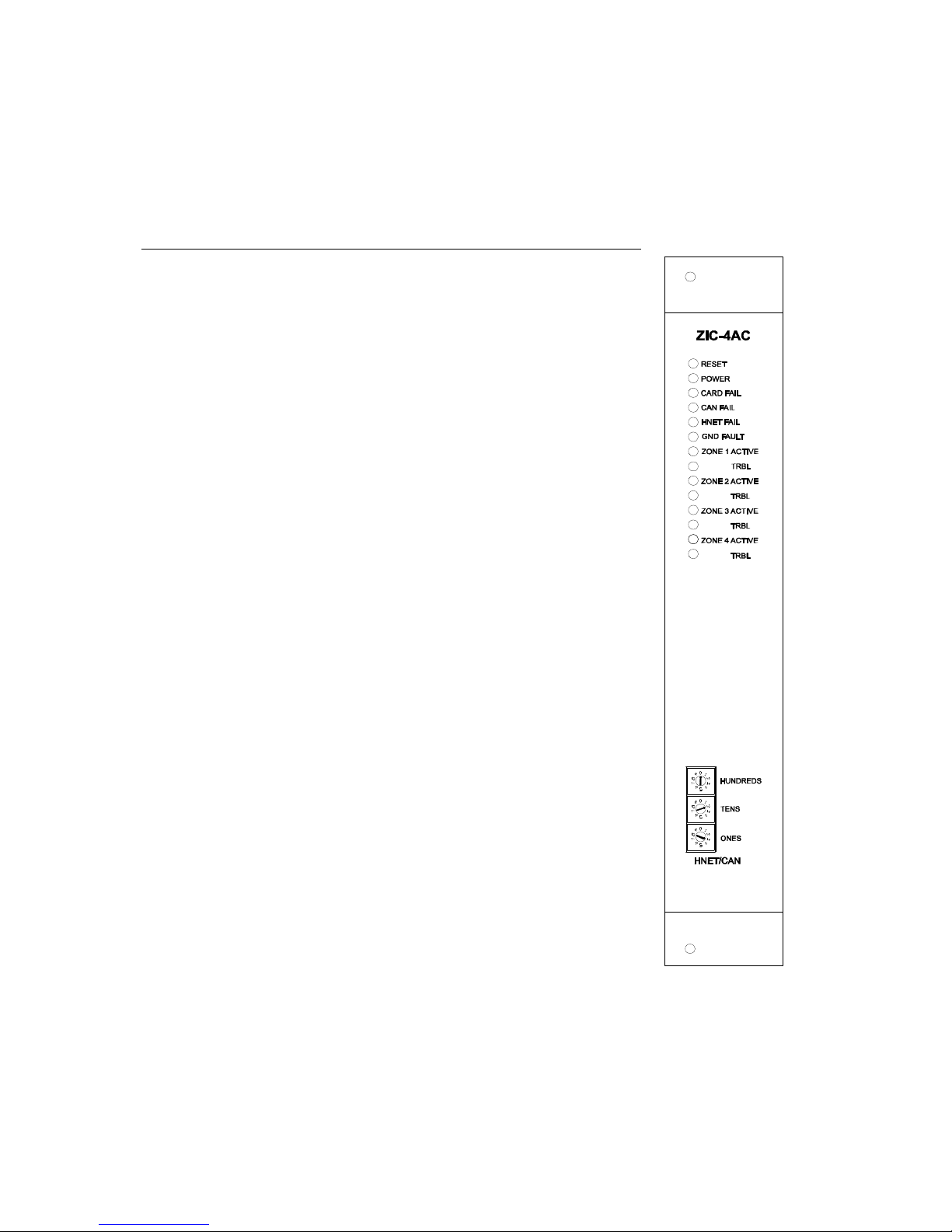
Figure 1
ZIC-4AC Zone
Interface Card
A24205-A334-B827 s
P/N 315-035850-2
1
Page 2

OPERATION The ZIC-4AC contains four Class A circuits. Each circuit is rated at 4A at
24VDC and has an input connected to the power source and an output where
the NAC devices are connected. The zone inputs are isolated from one
another and are supervised for the presence of power. This allows the use of
different power sources with different ground references. The zone output is
supervised for open and short circuit conditions while the zone is inactive and
allows different combinations of output configurations (Standard NAC or
Speaker) per card. Each ZIC- 4AC card occupies any one card slot in the CC5/CC-2 cardcage. The ZIC-4AC also has the capability to detect ground fault
on its zone output as indicated by a diagnostic LED.
Strobe unsynchronized:
Input 1is connected directly to output 1, output is ON steady . Same for In/Outputs 2, 3 and 4
Strobe synchronized:
Input 1 is connected directly to output 1, Output is ON for about 1 second,
then a ZIC-4AC onboard relay switch output polarity (+24V is now GND and
GND is now +24V). This will cause the strobes to flash. All ZIC-4AC outputs
configured as strobe sync will switch output polarity at the same time, also
outputs from other ZIC-4AC. Same for In-/Outputs 2, 3 and 4
Bulk amplification 1 channel:
Input 1is connected directly to output 1, output is ON steady. Same for In/Outputs 2, 3 and 4
Bulk amplification 2 channel:
This mode provides the possibility to choose between two different signal
for one speaker line. Signal one (A) has to be connected to input 1. Signal two
(B) has to be connected to input 2. A ZIC-4AC onboard input relay switches
automatically the correct signal to the outputs 1 and 2. The functionality is
identical for IN-/Output pairs 3 and 4.
Controls and Indicators The Front Panel of the ZIC-4AC contains one reset switch, thirteen LEDs,
and three CAN address switches as shown in Figure 1.
A Reset Switch is located on the top of the front panel. Pushing the reset
switch re-initializes the ZIC-4AC operation.
The LEDs follow the reset switch and their functions are defined as follows:
POWER (Green) Normally ON. When illuminated,
indicates that power for the ZIC-4AC is
applied to the card.
CARD FAIL (Yellow) Normally OFF. When illuminated,
indicates that the card microprocessor
has failed.
CAN FAIL (Yellow) Normally OFF. When illuminated,
indicates that the CAN communication
with the ZIC-4AC has terminated and
the card goes into degrade mode
HNET FAIL (Yellow) NOT USED
2
A24205-A334-B827
P/N 315-035850-2
Page 3
GND FAULT (Yellow) Normally OFF. When illuminated,
indicates that the ZIC-4AC has
detected either a negative or positive
ground fault on its field wiring.
ZONE 1 (2, 3, 4) ACTIVE (Red) Normally OFF. When illuminated,
indicates that Zone 1 (2, 3, 4) is active.
TROUBLE (Yellow) Normally OFF. When illuminated,
indicates that the ZIC-4AC has
detected a trouble on Zone 1 (open
circuit or short circuit).
Three rotary dial switches at the bottom of the front panel are used to set
the CAN network address of the ZIC-4AC.
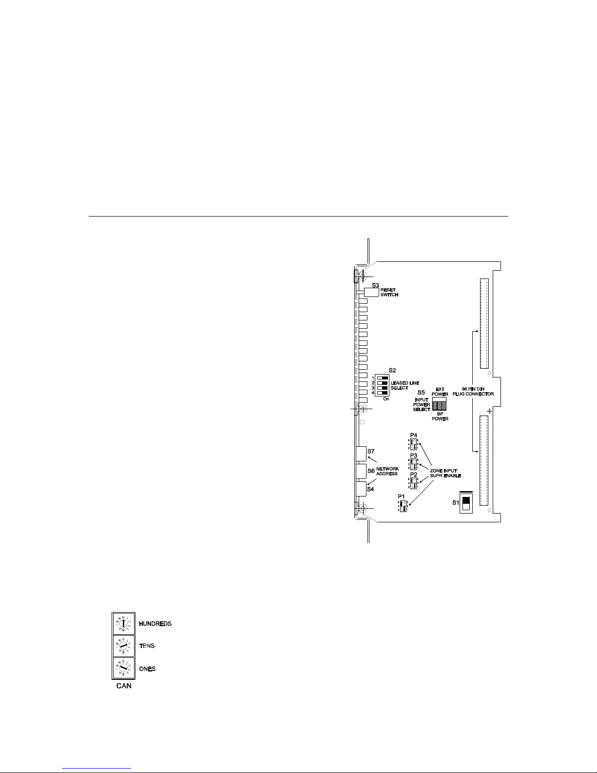
PRE-INSTALLATION The following components must be set prior to inserting the card to the CC-5
(refer to Figure 2):
S1: Not used
Switch position has to be off
(upper position)
S2: Not used
All four switch positions have to
be off (left position)
S3: Reset Switch
Momentarily Closed switch that
when pressed will initiate a hard
reset to the ZIC-4AC (similar to a
cold boot).
S5: Input Power Select
This switch selects the source of
voltage input to power the ZIC-
4AC. BP Power indicates that
the input is derived from the
backplane of the CC -2/CC-5 and
EXT Power indicates that the
input is derived from E5/E11
terminal of the CC-2/CC-5,
normally connected to nonpower limited output of the PSC-
12/PSX-12. It is important to take
into account the source of the
voltage during power
calculations.
Figure 2
ZIC-4AC Switch and Jumper Location
for Strobe usage
S4, S6, S7: Network Address Switch
Set the two-digit CAN network address for the ZIC-4AC using the three rotary
dial address switches located near the bottom of the front panel. (Refer to
Figure 1 for the location of the switches.) The address for the ZIC-4AC must
be the same as the address selected for it in the Zeus Programming Tool. To
set the address, turn the pointers on each of the three dials to the numbers
for the selected address. For example, if the address is 23, set the pointer for
the HUNDREDS dial to “0”, set the pointer for the TENS dial to “2”, and set
the pointer for the ONES dial to “3”. The range of allowable addresses is
from 001 to 099 (leading zeros must be used).
3
A24205-A334-B827
P/N 315-035850-2
Page 4
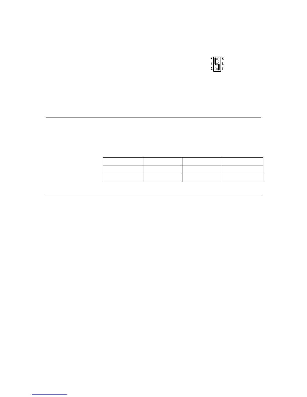
P1, P2, P3, P4: Input Supervision active / in-active
These headers select NAC input zone supervision being active or inactive. If
the usage application is set for speaker function, remove the shunt jumpers.
If the usage application is set for strobe place the two shunt jumpers of each
header between pins 1-3 and 4-6.
P1 selects NAC input supervision for Zone 1
P2 selects NAC input supervision for Zone 2
P3 selects NAC input supervision for Zone 3
P4 selects NAC input supervision for Zone 4
P5: Not used
No shunt jumpers set
J3: Not used
No shunt jumpers set
Output Zones The ZIC-4AC can be configured for the following usages:
Speaker zone one or two channel
Strobe, Bell, Horn steady (Unsynchronized) and pulsing (Synchronized)
ZIC-4AC Switch and Jumper Settings
Zone Usage S1 S2 Header Position
Speaker Zone OFF (up) OFF (left) none
NAC OFF (up) OFF (left) 1-3 and 4-6
Programming Options Each ZIC-4AC card is subdivided into four output circuits that can be
programmed independently of each other. In the Zeus Programming Tool,
highlight the selected ZIC -4AC Output Ckt in the Physical View and open the
Detail View - Properties to modify and/or define the following ZIC-4AC
output circuit properties:
CAN Address This address must match the
address set in the ZIC-4AC
hardware. (001 to 099)
Slot Location This defines the location where
the ZIC-4AC is inserted in the
CC-5/CC2.
Base Language Custom Message The message associated with the
ZIC-4AC output circuit.
Alternate Language Custom Message The message associated with the
ZIC-4AC output circuit in an
alternate language.
Disarm at Startup Determines if the ZIC-4AC
Output Ckt is disarmed after
initial power-up.
Degrade Alarm Activation Determines if Degrade Alarm will
activate the ZIC-4AC circuit when
asserted.
4
A24205-A334-B827
P/N 315-035850-2
Page 5

Wiring
Wiring Type Defines if the circuit is Class A or
Class B wiring type.
Silenceable Option Determines if the circuit is
Silenceable or Non-Silenceable.
Some restrictions apply to certain usage selections that are enforced by the
Zeus tool during Edit mode or Compile time.
Refer to the Zeus Quick Start Manual, A24205-A334-A828 (German) or
A24205-A334-B828 (English), or the Zeus self -help index for more information.
Disconnect BATTERY and AC prior to working on equipment
All field wiring to the ZIC-4AC is
connected to the terminal blocks of the
CC-5/CC-2 card cage slot in which it is
installed (Refer to Figure 3).
To Connect External Wiring
1. Loosen the screw of the
terminal by turning it
counterclockwise.
2. Insert the wire into the side of
the terminal block.
3. Tighten the screw of the
terminal block by turning it
clockwise.
The top terminals (1 through 8 and 9
through 16) are connected to the
notification appliance devices such as
bells, horns, strobes, speakers, etc. Each
zone has four terminal connections: (+),
Class A (+), (-), Class A (-). These
terminals are power limited.
The bottom terminals (17 through 24) are
Figure 3
ZIC-4AC Wiring The 24VDC Power
Lines To The ZIC- AC Slot In The CC-5
connected to the input power source of the NAC devices. Each zone has a (+)
terminal and (-) terminal. These terminals are not power limited.
Care must be taken when installing the zone input and zone output field
wiring to prevent possible cross wiring. This can cause severe damage to
the system when powered up or when zone is activated.
The screw terminals can accommodate one 12 -24 AWG (Ø 0.5mm –
2.5mm2) or two 16-24 AWG (Ø 0.5mm – 1.5mm2).
If the total output of all 4 zones exceeds 12 amps, a single PSC-12C cannot
be used to supply the ZIC-4AC. Refer to the PSC-12C Installation Instructions
A24205-A334-B798 for information when the total system load exceeds 12 amps.
5
A24205-A334-B827
P/N 315-035850-2
Page 6

INSTALLATION The ZIC-4AC plugs perpendicularly into one slot in the CC -5 card-cage via two
96-pin DIN connectors and can occupy any slot in the card cage. (Refer to
Figure 4.)
Insert the ZIC-4AC card into the card guides right side up (lettering on the
front panel is legible)
Slide the card in until the card edge connectors contact the receptacles on
the motherboard.
Verify that the DIN connectors of the card and the card -cage aligned properly.
The card can only plug in one direction to the card cage, if it does not align,
DO NOT FORCE the card.
Place thumbs on the front panel adjacent to the captive screws and gently
apply even pressure on the card until the connectors seat in the receptacles
on the motherboard.
Secure with the captive screws.
Figure 4
Installing The ZIC-4AC
6
A24205-A334-B827
P/N 315-035850-2
Page 7

ELECTRICAL RATINGS
24V Back Plane Current see NOTE below
Screw Terminal 24V Current Total Device Current
6.2V Back Plane Current 0
24V Standby Current Same as 24V Back Plane Current
The 24V backplane current is dependent on the usage and wiring type of
each ZICCkt of the ZIC-4AC. Listed below are the required current draws for
each zone and wiring type.
ZIC-4AC Backplane Current Requirement
Zone Usage Output Current
Requirement
Class A Current
Requirement
Not Used 0 0
Strobe – Sync. 17mA 6mA
Strobe – Unsync. 17mA 6mA
Speaker Zone 34mA 6mA
ZIC-4AC Module Current = 89mA
To calculate the maximum backplane current, the following equation should
be used:
ZIC-4AC Module Current + Zone 1 Usage Req.(See Table above)
+ Class A current (if Class A)
+ Zone 2 Usage Req.(See Table above)
+ Class A current (if Class A)
+ Zone 3 Usage Req.(See Table above)
+ Class A current (if Class A)
+ Zone 4 Usage Req.(See Table above)
+ Class A current (if Class A)
Example 1: If a ZIC-4AC has the following ZICCkt setting:
ZICCkt#1 - Speaker Zone Class A
ZICCkt#2 - Speaker Zone Class A
ZICCkt#3 - Speaker Zone Class A
ZICCkt#4 - Speaker Zone Class A
By applying the equation above, the maximum backplane current requirement
for this card will be determined.
Maximum Backplane Current =
89 + (34 + 6) + (34 + 6) + (34 + 6) + (34 + 6) = 249mA (worst case)
7
A24205-A334-B827
P/N 315-035850-2
Page 8

Example 2: If a ZIC-4AC has the following ZICCkt setting:
ZICCkt#1 - Strobe Unsync., Class A
ZICCkt#2 - Strobe Sync., Class A
ZICCkt#3 - Strobe Sync., Class B
ZICCkt#4 - not used
Maximum Backplane Current =
89 + (17 + 6) + (17 + 6) + (17 + 0) + (0 + 0) = 152mA
CONFIGURATIONS The ZIC-4AC zones can be configured for the following usages (Refer to
Figures 5 - 8):
NOTES
1. Wiring for each zone can either be
Class A or Class B.
2. All output circuits are power limited
3. Electrical Ratings:
Output Zone Supervisory:
4mA max @ 24VDC
Output Zone Alarm:
4A max @ 24VDC
4. EOL resistor , 24k ohms ,
1 watt , 5%, (comes with module
package)
EOL-Kit S24135-D55-A1
5. Polarity shown in active state.
6. Maximum line resistance is
dependent upon the maximum
current draw of connected
notification appliances when
activated. The field wiring
resistance cannot exceed the
maximum line resistance specified
for any given NAC current draw.
(See Table)
Current Draw 4.0A 3.5A 3.0A 2.5A 2.0A 1.5A 1.0A 0.5A
Max Line Resistance 0.8
ohms
Figure 5
ZIC-4AC Supervised Notification Appliance Wiring
1.0
ohms
1.2
ohms
1.5
ohms
2.0
ohms
2.7
ohms
8
4.2
ohms
8.7
ohms
A24205-A334-B827
P/N 315-035850-2
Page 9

Figure 6
ZIC-4AC Single-Channel Audio Wiring
NOTES
1. Wiring for each zone can either be Class A or Class B.
2. All output circuits are power limited.
3. Electrical Ratings:
Output Zone Supervisory: 4mA max @ 24VDC
Output Zone Active: 400 Watts max / zone
4. EOL resistor, 24k ohms, 1 watt, 5%, (comes with module package) EOL-Kit S24235-D55-A1.
5. Polarity shown in active state.
9
A24205-A334-B827
P/N 315-035850-2
Page 10

Figure 7
ZIC-4AC Two-Channel Audio Wiring
NOTES
1. Wiring for each zone can either be Class A or Class B.
2. All output circuits are power limited.
3. Electrical Ratings:
Output Zone Supervisory: 4mA max @ 24VDC
Output Zone Active: 400 Watts max / zone
4. EOL resistor, 24k ohms, 1 watt , 5%, (comes with module package) EOL-Kit S24135-D55-A1.
5. Polarity shown in active state.
6. For two channel speaker application, the channel with higher priority (EVAC) must be connected to inputs 2/4 and the
channel with the lower priority (ALERT) must be connected to inputs 1/3 to ensure proper switching operation of the ZIC-
4AC.
7. Verify that P1 - P4 are in the proper location for speaker application.
10
A24205-A334-B827
P/N 315-035850-2
Page 11

BATTERY
THERMISTOR
SWITCH
1
+ + +
REMOTE
LVM
CAN
NETWORK
CONNECTION
(24VDC @ 4A)
6
12
_
+
1
2
TB3
FMT
RISER
TB1
P5
1
P4
34
7
12
REMOTE
LVM
OUTPUT
ONE SLOT OF CC-5
-
-
-
-
BATTERY
CONNECTION
NON- POWER
LIMITED OUTPUT
(24VDC @ 12A Max.)
TO PSX-12C
OR CC-5/CC-2
P9
_
+
1
2
TB4
_
+
CIRCUIT
BREAKER
BATTERY
19
13
RELAY OUTPUTS
(2A @ 30VDC/
120VAC (.6PF)
TB2
O —
OFF
ON
TO PSX-12C
OR CC-5/CC-2
P12
24
18
CONNECTION
(INPUT)
GND
N
H
AC
Figure 8
ZIC-4AC Strobe Wiring With PSC-12C Power Supply
Notes
1. All output circuits are power limited
2. Electrical Ratings:
Output Supervisory Current:
2 mA max @ 24VDC
Output Alarm Current:
4A max @ 24VDC
3. Maximum line resistance: Refer to table on page 7.
4. Inputs can be daisy-chained provided that the power supply can sustain the power requirement of the output when
activated.
5. Refer to Zeus Quick Start Guide (A24235-A334-A828 (German)) (A24235-A334-B828 (English)) for information about
programming of releasing service.
11
A24205-A334-B827
P/N 315-035850-2
Page 12

For CE applications in Cerberus E100 systems refer to
Installation Instruction A24205-A334-B844 (English) or A24205-A334-A844 (German)
© Siemens Gebäudesicherheit GmbH & Co. oHG 2002
Siemens Building Technologies, Inc. Florham Park, New Jersey 07932
Siemens Building Technologies, Ltd. Brampton, Ontario L6T 5E4 CN
Issued by Siemens
Gebäudesicherheit GmbH & Co. oHG
D-80930 München
Delivery subject to availability;
right of technical modifications reserved.
Order No. A24205-A334-B836
(Edition 2)
P/N 315-035200-2
Printed in the Federal Republic of Germany
on environmental chlorine-free paper.
 Loading...