

Page 1
Installation Instructions
Model ZCT-8B
Zone Control Telephone Card Module
OPERATION
The Model ZCT-8B Zone Control Telephone
Card from Siemens Industry, Inc. has eight
telephone zones. The name indicates the following information:
ZCT – Zone Control Telephone card
8B – 8 Zone Style Y telephone zone output circuits
The ZCT-8B connects to the telephone riser
through the OMM-1 Output Master module.
All ZCT-8B zone circuits are supervised, protected, and for Class B (Style Y) zone use only.
The module provides both dial and busy tones.
Up to five telephones can be on line at the same
time.
The ZCT-8B occupies one of eleven
subaddresses of the OCC-1 Output Control Card
module. When installing a zone control module,
use the CSG-M (AccuLINK) configuration printout to locate the address of each zone control
card. Use switch S1 to set a unique address for
up to zone control cards as described below.
INSTALLATION
Remove all system power before installation
first battery and then AC. (To power up,
nect the AC first and then the battery.)
1. Remove the card from its protective bag. Do
not touch the gold edge of the board.
2. Refer to the function section of the CSG-M
configuration printout for the address of the
module.
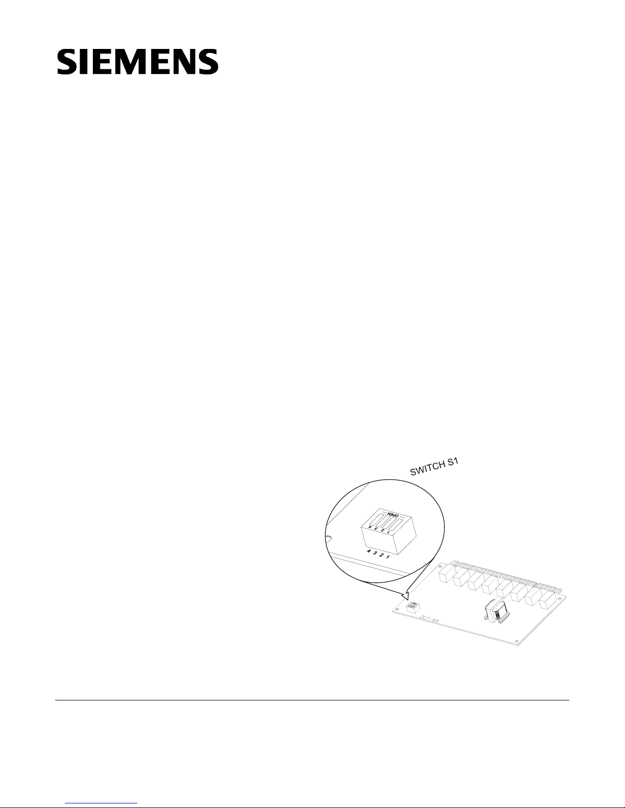
3. Set the card address on switch S1 using
switches SW1 – SW4.
a. Refer to Figure 1 for the location of S1.
b. Refer to Table 1 for switch settings (See
Note below).
con-
For additional information on the Voice System,
refer to the MXLV Manual, P/N 315-092036.
Siemens Industry, Inc.
Building Technologies Division
Florham Park, NJ
P/N 315-092105-7
Figure 1
ZCT-8B Module Board
Siemens Building Technologies, Ltd.
Fire Safety & Security Products
2 Kenview Boulevard
Brampton, Ontario
L6T 5E4 Canada
Page 2

TABLE 1
ADDR 4 3 2 1 ADDR 4 3 2 1
ILLEGAL O O O O 8XOOO
1 OOOX 9XOOX
2OOXO 10 X O X 0
3OOXX 11 X O X X
4OXOO ILLEGAL X X O O
5OXOX ILLEGAL X X O X
6OXXO ILLEGAL X X X O
7 O X X X ILLEGAL X X X X
X = SWITCH CLOSED OR ON, 0 = SWITCH OPEN OR OFF
NOTE:
To open a dipswitch, press down on the side of
the dipswitch marked OPEN. To close a
dipswitch, press down on the side of the
dipswitch opposite the side marked OPEN.
To open a slide switch, push the slide to the
side opposite the side marked ON. To close a
slide switch, push the slide to the side marked ON.
Do NOT install the card in its edge connector
until ALL OMM-1 field wiring is completed and
checked for shorts, opens, and other faults.
Refer to the Wiring Checkout Chart. Replace
the card in its protective bag if the wiring is not
complete.
Find the card slot key provided in the installation
kit with the ZCT-8B board. Place the card slot
in the OMM-1 edge connector for the ZCT-8B
key
as
shown in Figure 2. See Figure 3 for the exact
OMM PIN NUMBERS
Figure 2
Placing the Card Slot Key in the OMM-1
location of the key for this module. This prevents
installation of any other card type in the ZCT-8B
slot. Two other keys already installed in the
OMM-1 prevent reverse installation of the card in
the OMM-1 edge connectors. (See Figure 3.)
Place the card in its card edge connector correctly. The components on the board must face
the 22 position terminal block where the wiring is
terminated. Press the card firmly in place to be
sure it is seated properly in the edge connector.
FACTORY KEY 1
2
1
USER KEY
18
20
19
17
FACTORY KEY 2
Figure 3
Location of User Key for ZCT-8B
80
79
ELECTRICAL RATINGS
tnerruCeludoMCDV5evitcAAm51
tnerruCeludoMCDV42evitcA
tnerruCeludoMCDV42ybdnatSAm51
Maximum wire size: 14 AWG twisted pair, shielded
Minimum wire size: 18 AWG twisted pair, shielded
Am01+Am01
Maximum loop resistance: 10 ohms for both wires.
enozevitcarep
Outputs: Supervisory 9 VDC, 9mA max
Activated 12.5 VDC, 300mA max
End of line resistor: 10K, ¼W, ±1% (P/N 140-383467)
2
Page 3

WIRING
Refer to Figure 4.
All wiring must comply with national and local codes.
Terminate all unused outputs with an EOL resistor.
stinUenohpeleTelbitapmoC
103-TFnoitatSs'nedraWseireS
203-TFnoitatSs'nedraWseireS
303-JFkcaJ
403-JFkcolBlanimr
ALL ZONES SUPERVISED, POWER LIMITED
All Wiring must comply with National and Local Codes
Maximum Loop Resistance: 10 ohnms
Minimum Wire Size: 18 AWG
Maximum Wire Size: 14 AWG
Supervised Telephone Zone Connections
Supervised: 9 VDC, 9mA max
Activated: 12.5 VDC, 300mA max
Connect shield to negative zone terminal
NOTES
1. Refer to Wiring Specification for MXL, MXL-IQ
and MXLV Systems, P/N 315-092772 revision 6
or higher, for additional wiring information.
2. Short to Earth Ground on Terminals 1-16 will
cause ground fault.
eT/kcaJ
ZCT-8B Telephone Zone Wiring Diagram
Figure 4
3
Page 4

TRAHCTUOKCEHCGNIRIWB8-TCZ
NEEWTEBECNATSISER
SLANIMRET
2ot1
4ot3
6ot5
8ot7
ECNATSISER
DERISED
%1±K01;detrohseniL
ESUACELBISSOP
MELBORPFO
;nepoeniL
;LOEoN
LOEgnorW
01ot9
21ot11
41ot31
61o
t51
sissahcot22hguorht1geM1>gniriwnitrohS
3ot2
geM1>gniriwnitrohS
5ot4
7ot6
9ot8
11ot01
1ot21
3
51ot41
Siemens Industry, Inc.
Building Technologies Division
Florham Park, NJ
P/N 315-092105-7
.nahtsselsi=<,nahtretaergsi=>
Siemens Building Technologies, Ltd.
Fire Safety & Security Products
2 Kenview Boulevard
Brampton, Ontario
L6T 5E4 Canada
 Loading...