

Page 1
Installation Instruct ions
Model XMI
FireFinder-XLS/Desigo Fire Safety Modular/Cerberus PRO Modular to MDACT Interface
INTRODUCTION The Model XMI from Siemens Industry, Inc., provides an interface between the
FireFinder-XLS/Desigo Fire Safety Modular/Cerberus PRO Modular system and the
MDACT Digital Alarm Communicator. Both the XMI and the MDACT must be installed in the same MOM-2 cardcage. Mounting plate Model MOM2-XMP is required
to install the MOM-2 into the FireFinder-XLS/Desigo Fire Safety Modular/Cerberus
PRO Modular enclosure models CAB-1/-2/-3. The XMI has two 60-pin receptacles for
the FireFinder-XLS/Desigo Fire Safety Modular/Cerberus PRO Modular data bus
allowing the MOM-2 containing the XMI to be installed into any module location in
the rear of a CAB-1/-2/-3.
a local 5VDC and 24VDC for the MOM-2 which in turn provides power to the MDACT.
INSTALLATION
Remove all system power before installation, first battery, then AC. (To power up,
connect the AC first, then the battery.
The XMI receives 24V power from the PSC-12 and produces
P/N 315-034870-4
The XMI and MDACT install into a CAB-1/-2/-3 using the MOM2-XMP mounting plate
and a MOM-2 card cage.
1. Mount the MOM-2 (P/N 500-892766) to the MOM2-XMP (P/N 500-634822)
mounting plate using the screws supplied with the MOM2-XMP. The
MOM2-XMP adapts the MOM-2 to the module mounting locations in the
rear of the CAB-1/-2/-3. (Refer to Figure 1.)
2. Configure the MDACT, refer to Installation Instructions P/N 315-099351.
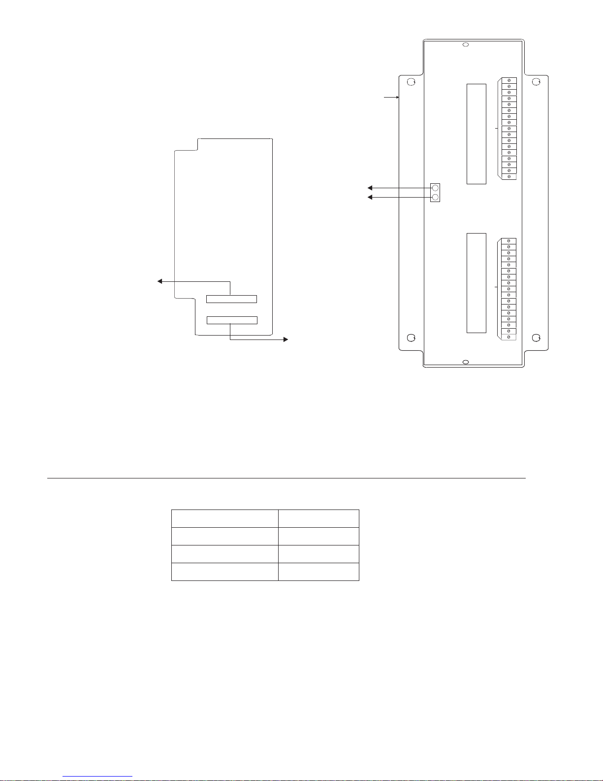
3. Install the MDACT into the MOM-2 in mounting slot P4. (Refer to Figure 1.)
4. Install the XMI into the MOM-2 in mounting slot P2. (Refer to Figure 1.)
5. Mount the MOM2-XMP on the CAB-MP in the rear of the CAB-1/-2/-3.
6. Connect the 60-pin 12 inch ribbon cable (provided) from JP1to the previous
CC-5/CC-2/PSC-12/PSX-12. If the XMI is mounted on the first row and you
are connecting to a CC-5/CC-2/PSC-12/PSX-12 on the second row, use 60pin 42 inch ribbon cable P/N 599-633997 (not provided). (Refer to Figure 1.)
7. If required, use a second 60-pin ribbon cable to connect JP2 to the next
CC-5/CC-2/PSC-12/PSX-12. (Refer to Figure 1.)
Building Building
Building
Building Building
Siemens Siemens
Siemens
Siemens Siemens
TT
ecec
hnologies Dihnologies Di
T
ec
hnologies Di
TT
ecec
hnologies Dihnologies Di
IndustryIndustry
Industry
IndustryIndustry
visionvision
vision
visionvision
,,
Inc. Inc.
,
Inc.
,,
Inc. Inc.
Page 2
NOTE:
Refer to MDACT Installation Instructions, P/N 315-099351, for
MDACT configuration and wiring instructions.
XMI
MOM2-XMP
MOM-2
P4
M
D
A
C
T
TB4
DO NOT USE
60-pin ribbon cable
(P/N 599-633997) to next
CC-5/CC-2/PSC-12/PSX-12,
Figure 1
Installing the XMI
if required
(WIRE SIZE 18AWG-12AWG)
TO PSC-12, TB3
24V
24V RET
TB6
+
-
X
JP2
JP1
60-pin ribbon cable
(P/N 599-633997) from
CC-5/CC-2/PSC-12/PSX-12
8. Connect 24V from TB6 on the MOM-2 to 24V on the PSC-12 with 18AWG12AWG wire. (Refer to Figure 1.)
M
I
P2
DO NOT USE
TB2
ELECTRICAL RATINGS
Refer to MDACT Installation Instructions, P/N 315-099351, for electrical ratings. Be
sure to include the MDACT in PSC-12/PSX-12 power supply loading and battery
calculations.
Siemens Industry, Inc.
Building Technologies Division
tnerruCenalPkcaBV420
tnerruCV42lanimreTwercSAm5
tnerruCenalPkcaBV2.60
tnerruCybdnatSV42Am5
P/N 315-034870-32
Page 3

Cyber security disclaimer
Siemens products and solutions provide security functions to ensure the secure operation of building comfort,
fire safety, security management and physical security systems. The security functions on these products and
solutions are important components of a comprehensive security concept.
It is, however, necessary to implement and maintain a comprehensive, state-of-the-art security concept that is
customized to individual security needs. Such a security concept may result in additional site-specific
preventive action to ensure that the building comfort, fire safety, security management or physical security
system for your site are operated in a secure manner. These measures may include, but are not limited to,
separating networks, physically protecting system components, user awareness programs, defense in depth,
etc.
For additional information on building technology security and our offerings, contact your Siemens sales or
project department. We strongly recommend customers to follow our security advisories, which provide
information on the latest security threats, patches and other mitigation measures.
http://www.siemens.com/cert/en/cert-security-advisories.htm
Siemens Industry, Inc.
Building Technologies Division
P/N 315-034870-33
Page 4

Siemens Industry, Inc.
Building Technologies Division
Florham Park, NJ
Siemens Canada, Ltd.
1577 North Service Road East
Oakville, Ontario
L6H 0H6 Canada
P/N 315-034870-4Document ID A6V10239134
 Loading...