

Page 1
Equipment for Special Machines
aaaaaaaaaaaaaaaaaaaaaaaaaaaaaaaaaaaaaaaaaaaaaaaaaaaaaaaaaaaaaaaaaaaaaaaaaaaaaaaaaaaaaaaaaaaaaaaaaaaaaaaaaaaaaaaaaaaaaaaaaaaaaaaaaaa
a
a
a
a
a
a
a
a
a
a
a
a
a
a
a
a
a
a
a
a
a
a
a
a
a
a
a
a
a
a
a
a
a
a
a
a
a
a
a
a
a
a
a
a
a
a
a
a
a
a
a
a
a
a
a
a
a
a
a
a
a
a
a
a
a
a
a
a
a
a
a
a
a
a
a
a
a
a
a
a
a
a
a
a
a
a
a
a
a
a
a
a
a
a
a
a
a
a
a
a
a
a
a
a
a
a
a
a
a
a
a
a
a
a
a
a
a
a
a
a
a
a
a
a
a
a
a
a
a
a
a
a
a
a
a
a
a
a
a
a
a
a
a
a
a
a
a
a
a
a
a
a
a
a
a
a
a
a
a
a
a
a
a
a
a
a
a
a
a
a
a
a
a
a
a
a
a
a
a
a
a
a
a
a
a
a
a
a
a
a
a
a
a
a
a
a
a
a
a
a
a
a
a
a
a
a
a
a
a
a
a
a
a
a
a
a
a
a
a
a
a
a
a
a
a
a
a
a
a
a
a
a
a
a
a
a
a
a
a
a
a
a
a
a
a
a
a
a
a
a
a
a
a
a
a
a
a
a
aaaaaaaaaaaaaaaaaaaaaaaaaaaaaaaaaaaaaaaaaaaaaaaaaaaaaaaaaaaaaaaaaaaaaaaaaaaaaaaaaaaaaaaaaaaaaaaaaaaaaaaaaaaaaaaaaaaaaaaaaaaaaaaaaaa
a
a
a
a
a
a
a
a
a
a
a
a
WF 723 C
Positioning Module
aaaaaaaaaaaaaaaaaaaaaaaaaaaaaaaaaaaaaaaaaaaaaaaaaaaaaaaaaaaaaaaaaaaaaaaaaaaaaaaaaaaaaaaaaaaaaaaaaaaaaaaaaaaaaaaaaaaaaaaaaaaaaaaaa
aaaaaaaaaaaaaaaaaaaaaaaaaaaaaaaaaaaaaaaaaaaaaaaaaaaaaaaaaaaaaaaaaaaaaaaaaaaaaaaaaaaaaaaaaaaaaaaaaaaaaaaaaaaaaaaaaaaaaaaaaaaaaaaaa
aaaaaaaaaaaaaaaaaaaaaaaaaaaaaaaaaaaaaaaaaaaaaaaaaaaaaaaaaaaaaaaaaaaaaaaaaaaaaaaaaaaaaaaaaaaaaaaaaaaaaaaaaaaaaaaaaaaaaaaaaaaaaaaaa
aaaaaaaaaaaaaaaaaaaaaaaaaaaaaaaaaaaaaaaaaaaaaaaaaaaaaaaaaaaaaaaaaaaaaaaaaaaaaaaaaaaaaaaaaaaaaaaaaaaaaaaaaaaaaaaaaaaaaaaaaaaaaaaaa
aaaaaaaaaaaaaaaaaaaaaaaaaaaaaaaaaaaaaaaaaaaaaaaaaaaaaaaaaaaaaaaaaaaaaaaaaaaaaaaaaaaaaaaaaaaaaaaaaaaaaaaaaaaaaaaaaaaaaaaaaaaaaaaaa
aaaaaaaaaaaaaaaaaaaaaaaaaaaaaaaaaaaaaaaaaaaaaaaaaaaaaaaaaaaaaaaaaaaaaaaaaaaaaaaaaaaaaaaaaaaaaaaaaaaaaaaaaaaaaaaaaaaaaaaaaaaaaaaaa
aaaaaaaaaaaaaaaaaaaaaaaaaaaaaaaaaaaaaaaaaaaaaaaaaaaaaaaaaaaaaaaaaaaaaaaaaaaaaaaaaaaaaaaaaaaaaaaaaaaaaaaaaaaaaaaaaaaaaaaaaaaaaaaaa
aaaaaaaaaaaaaaaaaaaaaaaaaaaaaaaaaaaaaaaaaaaaaaaaaaaaaaaaaaaaaaaaaaaaaaaaaaaaaaaaaaaaaaaaaaaaaaaaaaaaaaaaaaaaaaaaaaaaaaaaaaaaaaaaa
aaaaaaaaaaaaaaaaaaaaaaaaaaaaaaaaaaaaaaaaaaaaaaaaaaaaaaaaaaaaaaaaaaaaaaaaaaaaaaaaaaaaaaaaaaaaaaaaaaaaaaaaaaaaaaaaaaaaaaaaaaaaaaaaa
aaaaaaaaaaaaaaaaaaaaaaaaaaaaaaaaaaaaaaaaaaaaaaaaaaaaaaaaaaaaaaaaaaaaaaaaaaaaaaaaaaaaaaaaaaaaaaaaaaaaaaaaaaaaaaaaaaaaaaaaaaaaaaaaa
aaaaaaaaaaaaaaaaaaaaaaaaaaaaaaaaaaaaaaaaaaaaaaaaaaaaaaaaaaaaaaaaaaaaaaaaaaaaaaaaaaaaaaaaaaaaaaaaaaaaaaaaaaaaaaaaaaaaaaaaaaaaaaaaa
aaaaaaaaaaaaaaaaaaaaaaaaaaaaaaaaaaaaaaaaaaaaaaaaaaaaaaaaaaaaaaaaaaaaaaaaaaaaaaaaaaaaaaaaaaaaaaaaaaaaaaaaaaaaaaaaaaaaaaaaaaaaaaaaa
aaaaaaaaaaaaaaaaaaaaaaaaaaaaaaaaaaaaaaaaaaaaaaaaaaaaaaaaaaaaaaaaaaaaaaaaaaaaaaaaaaaaaaaaaaaaaaaaaaaaaaaaaaaaaaaaaaaaaaaaaaaaaaaaa
aaaaaaaaaaaaaaaaaaaaaaaaaaaaaaaaaaaaaaaaaaaaaaaaaaaaaaaaaaaaaaaaaaaaaaaaaaaaaaaaaaaaaaaaaaaaaaaaaaaaaaaaaaaaaaaaaaaaaaaaaaaaaaaaa
aaaaaaaaaaaaaaaaaaaaaaaaaaaaaaaaaaaaaaaaaaaaaaaaaaaaaaaaaaaaaaaaaaaaaaaaaaaaaaaaaaaaaaaaaaaaaaaaaaaaaaaaaaaaaaaaaaaaaaaaaaaaaaaaa
aaaaaaaaaaaaaaaaaaaaaaaaaaaaaaaaaaaaaaaaaaaaaaaaaaaaaaaaaaaaaaaaaaaaaaaaaaaaaaaaaaaaaaaaaaaaaaaaaaaaaaaaaaaaaaaaaaaaaaaaaaaaaaaaa
aaaaaaaaaaaaaaaaaaaaaaaaaaaaaaaaaaaaaaaaaaaaaaaaaaaaaaaaaaaaaaaaaaaaaaaaaaaaaaaaaaaaaaaaaaaaaaaaaaaaaaaaaaaaaaaaaaaaaaaaaaaaaaaaa
aaaaaaaaaaaaaaaaaaaaaaaaaaaaaaaaaaaaaaaaaaaaaaaaaaaaaaaaaaaaaaaaaaaaaaaaaaaaaaaaaaaaaaaaaaaaaaaaaaaaaaaaaaaaaaaaaaaaaaaaaaaaaaaaa
aaaaaaaaaaaaaaaaaaaaaaaaaaaaaaaaaaaaaaaaaaaaaaaaaaaaaaaaaaaaaaaaaaaaaaaaaaaaaaaaaaaaaaaaaaaaaaaaaaaaaaaaaaaaaaaaaaaaaaaaaaaaaaaaa
aaaaaaaaaaaaaaaaaaaaaaaaaaaaaaaaaaaaaaaaaaaaaaaaaaaaaaaaaaaaaaaaaaaaaaaaaaaaaaaaaaaaaaaaaaaaaaaaaaaaaaaaaaaaaaaaaaaaaaaaaaaaaaaaa
aaaaaaaaaaaaaaaaaaaaaaaaaaaaaaaaaaaaaaaaaaaaaaaaaaaaaaaaaaaaaaaaaaaaaaaaaaaaaaaaaaaaaaaaaaaaaaaaaaaaaaaaaaaaaaaaaaaaaaaaaaaaaaaaa
aaaaaaaaaaaaaaaaaaaaaaaaaaaaaaaaaaaaaaaaaaaaaaaaaaaaaaaaaaaaaaaaaaaaaaaaaaaaaaaaaaaaaaaaaaaaaaaaaaaaaaaaaaaaaaaaaaaaaaaaaaaaaaaaa
aaaaaaaaaaaaaaaaaaaaaaaaaaaaaaaaaaaaaaaaaaaaaaaaaaaaaaaaaaaaaaaaaaaaaaaaaaaaaaaaaaaaaaaaaaaaaaaaaaaaaaaaaaaaaaaaaaaaaaaaaaaaaaaaa
aaaaaaaaaaaaaaaaaaaaaaaaaaaaaaaaaaaaaaaaaaaaaaaaaaaaaaaaaaaaaaaaaaaaaaaaaaaaaaaaaaaaaaaaaaaaaaaaaaaaaaaaaaaaaaaaaaaaaaaaaaaaaaaaa
aaaaaaaaaaaaaaaaaaaaaaaaaaaaaaaaaaaaaaaaaaaaaaaaaaaaaaaaaaaaaaaaaaaaaaaaaaaaaaaaaaaaaaaaaaaaaaaaaaaaaaaaaaaaaaaaaaaaaaaaaaaaaaaaa
aaaaaaaaaaaaaaaaaaaaaaaaaaaaaaaaaaaaaaaaaaaaaaaaaaaaaaaaaaaaaaaaaaaaaaaaaaaaaaaaaaaaaaaaaaaaaaaaaaaaaaaaaaaaaaaaaaaaaaaaaaaaaaaaa
aaaaaaaaaaaaaaaaaaaaaaaaaaaaaaaaaaaaaaaaaaaaaaaaaaaaaaaaaaaaaaaaaaaaaaaaaaaaaaaaaaaaaaaaaaaaaaaaaaaaaaaaaaaaaaaaaaaaaaaaaaaaaaaaa
aaaaaaaaaaaaaaaaaaaaaaaaaaaaaaaaaaaaaaaaaaaaaaaaaaaaaaaaaaaaaaaaaaaaaaaaaaaaaaaaaaaaaaaaaaaaaaaaaaaaaaaaaaaaaaaaaaaaaaaaaaaaaaaaa
aaaaaaaaaaaaaaaaaaaaaaaaaaaaaaaaaaaaaaaaaaaaaaaaaaaaaaaaaaaaaaaaaaaaaaaaaaaaaaaaaaaaaaaaaaaaaaaaaaaaaaaaaaaaaaaaaaaaaaaaaaaaaaaaa
aaaaaaaaaaaaaaaaaaaaaaaaaaaaaaaaaaaaaaaaaaaaaaaaaaaaaaaaaaaaaaaaaaaaaaaaaaaaaaaaaaaaaaaaaaaaaaaaaaaaaaaaaaaaaaaaaaaaaaaaaaaaaaaaa
aaaaaaaaaaaaaaaaaaaaaaaaaaaaaaaaaaaaaaaaaaaaaaaaaaaaaaaaaaaaaaaaaaaaaaaaaaaaaaaaaaaaaaaaaaaaaaaaaaaaaaaaaaaaaaaaaaaaaaaaaaaaaaaaa
aaaaaaaaaaaaaaaaaaaaaaaaaaaaaaaaaaaaaaaaaaaaaaaaaaaaaaaaaaaaaaaaaaaaaaaaaaaaaaaaaaaaaaaaaaaaaaaaaaaaaaaaaaaaaaaaaaaaaaaaaaaaaaaaa
aaaaaaaaaaaaaaaaaaaaaaaaaaaaaaaaaaaaaaaaaaaaaaaaaaaaaaaaaaaaaaaaaaaaaaaaaaaaaaaaaaaaaaaaaaaaaaaaaaaaaaaaaaaaaaaaaaaaaaaaaaaaaaaaa
aaaaaaaaaaaaaaaaaaaaaaaaaaaaaaaaaaaaaaaaaaaaaaaaaaaaaaaaaaaaaaaaaaaaaaaaaaaaaaaaaaaaaaaaaaaaaaaaaaaaaaaaaaaaaaaaaaaaaaaaaaaaaaaaa
aaaaaaaaaaaaaaaaaaaaaaaaaaaaaaaaaaaaaaaaaaaaaaaaaaaaaaaaaaaaaaaaaaaaaaaaaaaaaaaaaaaaaaaaaaaaaaaaaaaaaaaaaaaaaaaaaaaaaaaaaaaaaaaaa
aaaaaaaaaaaaaaaaaaaaaaaaaaaaaaaaaaaaaaaaaaaaaaaaaaaaaaaaaaaaaaaaaaaaaaaaaaaaaaaaaaaaaaaaaaaaaaaaaaaaaaaaaaaaaaaaaaaaaaaaaaaaaaaaa
aaaaaaaaaaaaaaaaaaaaaaaaaaaaaaaaaaaaaaaaaaaaaaaaaaaaaaaaaaaaaaaaaaaaaaaaaaaaaaaaaaaaaaaaaaaaaaaaaaaaaaaaaaaaaaaaaaaaaaaaaaaaaaaaa
aaaaaaaaaaaaaaaaaaaaaaaaaaaaaaaaaaaaaaaaaaaaaaaaaaaaaaaaaaaaaaaaaaaaaaaaaaaaaaaaaaaaaaaaaaaaaaaaaaaaaaaaaaaaaaaaaaaaaaaaaaaaaaaaa
aaaaaaaaaaaaaaaaaaaaaaaaaaaaaaaaaaaaaaaaaaaaaaaaaaaaaaaaaaaaaaaaaaaaaaaaaaaaaaaaaaaaaaaaaaaaaaaaaaaaaaaaaaaaaaaaaaaaaaaaaaaaaaaaa
aaaaaaaaaaaaaaaaaaaaaaaaaaaaaaaaaaaaaaaaaaaaaaaaaaaaaaaaaaaaaaaaaaaaaaaaaaaaaaaaaaaaaaaaaaaaaaaaaaaaaaaaaaaaaaaaaaaaaaaaaaaaaaaaa
aaaaaaaaaaaaaaaaaaaaaaaaaaaaaaaaaaaaaaaaaaaaaaaaaaaaaaaaaaaaaaaaaaaaaaaaaaaaaaaaaaaaaaaaaaaaaaaaaaaaaaaaaaaaaaaaaaaaaaaaaaaaaaaaa
aaaaaaaaaaaaaaaaaaaaaaaaaaaaaaaaaaaaaaaaaaaaaaaaaaaaaaaaaaaaaaaaaaaaaaaaaaaaaaaaaaaaaaaaaaaaaaaaaaaaaaaaaaaaaaaaaaaaaaaaaaaaaaaaa
aaaaaaaaaaaaaaaaaaaaaaaaaaaaaaaaaaaaaaaaaaaaaaaaaaaaaaaaaaaaaaaaaaaaaaaaaaaaaaaaaaaaaaaaaaaaaaaaaaaaaaaaaaaaaaaaaaaaaaaaaaaaaaaaa
aaaaaaaaaaaaaaaaaaaaaaaaaaaaaaaaaaaaaaaaaaaaaaaaaaaaaaaaaaaaaaaaaaaaaaaaaaaaaaaaaaaaaaaaaaaaaaaaaaaaaaaaaaaaaaaaaaaaaaaaaaaaaaaaa
aaaaaaaaaaaaaaaaaaaaaaaaaaaaaaaaaaaaaaaaaaaaaaaaaaaaaaaaaaaaaaaaaaaaaaaaaaaaaaaaaaaaaaaaaaaaaaaaaaaaaaaaaaaaaaaaaaaaaaaaaaaaaaaaa
aaaaaaaaaaaaaaaaaaaaaaaaaaaaaaaaaaaaaaaaaaaaaaaaaaaaaaaaaaaaaaaaaaaaaaaaaaaaaaaaaaaaaaaaaaaaaaaaaaaaaaaaaaaaaaaaaaaaaaaaaaaaaaaaa
aaaaaaaaaaaaaaaaaaaaaaaaaaaaaaaaaaaaaaaaaaaaaaaaaaaaaaaaaaaaaaaaaaaaaaaaaaaaaaaaaaaaaaaaaaaaaaaaaaaaaaaaaaaaaaaaaaaaaaaaaaaaaaaaa
aaaaaaaaaaaaaaaaaaaaaaaaaaaaaaaaaaaaaaaaaaaaaaaaaaaaaaaaaaaaaaaaaaaaaaaaaaaaaaaaaaaaaaaaaaaaaaaaaaaaaaaaaaaaaaaaaaaaaaaaaaaaaaaaa
aaaaaaaaaaaaaaaaaaaaaaaaaaaaaaaaaaaaaaaaaaaaaaaaaaaaaaaaaaaaaaaaaaaaaaaaaaaaaaaaaaaaaaaaaaaaaaaaaaaaaaaaaaaaaaaaaaaaaaaaaaaaaaaaa
aaaaaaaaaaaaaaaaaaaaaaaaaaaaaaaaaaaaaaaaaaaaaaaaaaaaaaaaaaaaaaaaaaaaaaaaaaaaaaaaaaaaaaaaaaaaaaaaaaaaaaaaaaaaaaaaaaaaaaaaaaaaaaaaa
aaaaaaaaaaaaaaaaaaaaaaaaaaaaaaaaaaaaaaaaaaaaaaaaaaaaaaaaaaaaaaaaaaaaaaaaaaaaaaaaaaaaaaaaaaaaaaaaaaaaaaaaaaaaaaaaaaaaaaaaaaaaaaaaa
aaaaaaaaaaaaaaaaaaaaaaaaaaaaaaaaaaaaaaaaaaaaaaaaaaaaaaaaaaaaaaaaaaaaaaaaaaaaaaaaaaaaaaaaaaaaaaaaaaaaaaaaaaaaaaaaaaaaaaaaaaaaaaaaa
aaaaaaaaaaaaaaaaaaaaaaaaaaaaaaaaaaaaaaaaaaaaaaaaaaaaaaaaaaaaaaaaaaaaaaaaaaaaaaaaaaaaaaaaaaaaaaaaaaaaaaaaaaaaaaaaaaaaaaaaaaaaaaaaa
aaaaaaaaaaaaaaaaaaaaaaaaaaaaaaaaaaaaaaaaaaaaaaaaaaaaaaaaaaaaaaaaaaaaaaaaaaaaaaaaaaaaaaaaaaaaaaaaaaaaaaaaaaaaaaaaaaaaaaaaaaaaaaaaa
aaaaaaaaaaaaaaaaaaaaaaaaaaaaaaaaaaaaaaaaaaaaaaaaaaaaaaaaaaaaaaaaaaaaaaaaaaaaaaaaaaaaaaaaaaaaaaaaaaaaaaaaaaaaaaaaaaaaaaaaaaaaaaaaa
aaaaaaaaaaaaaaaaaaaaaaaaaaaaaaaaaaaaaaaaaaaaaaaaaaaaaaaaaaaaaaaaaaaaaaaaaaaaaaaaaaaaaaaaaaaaaaaaaaaaaaaaaaaaaaaaaaaaaaaaaaaaaaaaa
aaaaaaaaaaaaaaaaaaaaaaaaaaaaaaaaaaaaaaaaaaaaaaaaaaaaaaaaaaaaaaaaaaaaaaaaaaaaaaaaaaaaaaaaaaaaaaaaaaaaaaaaaaaaaaaaaaaaaaaaaaaaaaaaa
aaaaaaaaaaaaaaaaaaaaaaaaaaaaaaaaaaaaaaaaaaaaaaaaaaaaaaaaaaaaaaaaaaaaaaaaaaaaaaaaaaaaaaaaaaaaaaaaaaaaaaaaaaaaaaaaaaaaaaaaaaaaaaaaa
aaaaaaaaaaaaaaaaaaaaaaaaaaaaaaaaaaaaaaaaaaaaaaaaaaaaaaaaaaaaaaaaaaaaaaaaaaaaaaaaaaaaaaaaaaaaaaaaaaaaaaaaaaaaaaaaaaaaaaaaaaaaaaaaa
aaaaaaaaaaaaaaaaaaaaaaaaaaaaaaaaaaaaaaaaaaaaaaaaaaaaaaaaaaaaaaaaaaaaaaaaaaaaaaaaaaaaaaaaaaaaaaaaaaaaaaaaaaaaaaaaaaaaaaaaaaaaaaaaa
aaaaaaaaaaaaaaaaaaaaaaaaaaaaaaaaaaaaaaaaaaaaaaaaaaaaaaaaaaaaaaaaaaaaaaaaaaaaaaaaaaaaaaaaaaaaaaaaaaaaaaaaaaaaaaaaaaaaaaaaaaaaaaaaa
aaaaaaaaaaaaaaaaaaaaaaaaaaaaaaaaaaaaaaaaaaaaaaaaaaaaaaaaaaaaaaaaaaaaaaaaaaaaaaaaaaaaaaaaaaaaaaaaaaaaaaaaaaaaaaaaaaaaaaaaaaaaaaaaa
aaaaaaaaaaaaaaaaaaaaaaaaaaaaaaaaaaaaaaaaaaaaaaaaaaaaaaaaaaaaaaaaaaaaaaaaaaaaaaaaaaaaaaaaaaaaaaaaaaaaaaaaaaaaaaaaaaaaaaaaaaaaaaaaa
aaaaaaaaaaaaaaaaaaaaaaaaaaaaaaaaaaaaaaaaaaaaaaaaaaaaaaaaaaaaaaaaaaaaaaaaaaaaaaaaaaaaaaaaaaaaaaaaaaaaaaaaaaaaaaaaaaaaaaaaaaaaaaaaa
aaaaaaaaaaaaaaaaaaaaaaaaaaaaaaaaaaaaaaaaaaaaaaaaaaaaaaaaaaaaaaaaaaaaaaaaaaaaaaaaaaaaaaaaaaaaaaaaaaaaaaaaaaaaaaaaaaaaaaaaaaaaaaaaa
aaaaaaaaaaaaaaaaaaaaaaaaaaaaaaaaaaaaaaaaaaaaaaaaaaaaaaaaaaaaaaaaaaaaaaaaaaaaaaaaaaaaaaaaaaaaaaaaaaaaaaaaaaaaaaaaaaaaaaaaaaaaaaaaa
aaaaaaaaaaaaaaaaaaaaaaaaaaaaaaaaaaaaaaaaaaaaaaaaaaaaaaaaaaaaaaaaaaaaaaaaaaaaaaaaaaaaaaaaaaaaaaaaaaaaaaaaaaaaaaaaaaaaaaaaaaaaaaaaa
aaaaaaaaaaaaaaaaaaaaaaaaaaaaaaaaaaaaaaaaaaaaaaaaaaaaaaaaaaaaaaaaaaaaaaaaaaaaaaaaaaaaaaaaaaaaaaaaaaaaaaaaaaaaaaaaaaaaaaaaaaaaaaaaa
aaaaaaaaaaaaaaaaaaaaaaaaaaaaaaaaaaaaaaaaaaaaaaaaaaaaaaaaaaaaaaaaaaaaaaaaaaaaaaaaaaaaaaaaaaaaaaaaaaaaaaaaaaaaaaaaaaaaaaaaaaaaaaaaa
aaaaaaaaaaaaaaaaaaaaaaaaaaaaaaaaaaaaaaaaaaaaaaaaaaaaaaaaaaaaaaaaaaaaaaaaaaaaaaaaaaaaaaaaaaaaaaaaaaaaaaaaaaaaaaaaaaaaaaaaaaaaaaaaa
aaaaaaaaaaaaaaaaaaaaaaaaaaaaaaaaaaaaaaaaaaaaaaaaaaaaaaaaaaaaaaaaaaaaaaaaaaaaaaaaaaaaaaaaaaaaaaaaaaaaaaaaaaaaaaaaaaaaaaaaaaaaaaaaa
aaaaaaaaaaaaaaaaaaaaaaaaaaaaaaaaaaaaaaaaaaaaaaaaaaaaaaaaaaaaaaaaaaaaaaaaaaaaaaaaaaaaaaaaaaaaaaaaaaaaaaaaaaaaaaaaaaaaaaaaaaaaaaaaa
aaaaaaaaaaaaaaaaaaaaaaaaaaaaaaaaaaaaaaaaaaaaaaaaaaaaaaaaaaaaaaaaaaaaaaaaaaaaaaaaaaaaaaaaaaaaaaaaaaaaaaaaaaaaaaaaaaaaaaaaaaaaaaaaa
aaaaaaaaaaaaaaaaaaaaaaaaaaaaaaaaaaaaaaaaaaaaaaaaaaaaaaaaaaaaaaaaaaaaaaaaaaaaaaaaaaaaaaaaaaaaaaaaaaaaaaaaaaaaaaaaaaaaaaaaaaaaaaaaa
aaaaaaaaaaaaaaaaaaaaaaaaaaaaaaaaaaaaaaaaaaaaaaaaaaaaaaaaaaaaaaaaaaaaaaaaaaaaaaaaaaaaaaaaaaaaaaaaaaaaaaaaaaaaaaaaaaaaaaaaaaaaaaaaa
aaaaaaaaaaaaaaaaaaaaaaaaaaaaaaaaaaaaaaaaaaaaaaaaaaaaaaaaaaaaaaaaaaaaaaaaaaaaaaaaaaaaaaaaaaaaaaaaaaaaaaaaaaaaaaaaaaaaaaaaaaaaaaaaa
aaaaaaaaaaaaaaaaaaaaaaaaaaaaaaaaaaaaaaaaaaaaaaaaaaaaaaaaaaaaaaaaaaaaaaaaaaaaaaaaaaaaaaaaaaaaaaaaaaaaaaaaaaaaaaaaaaaaaaaaaaaaaaaaa
aaaaaaaaaaaaaaaaaaaaaaaaaaaaaaaaaaaaaaaaaaaaaaaaaaaaaaaaaaaaaaaaaaaaaaaaaaaaaaaaaaaaaaaaaaaaaaaaaaaaaaaaaaaaaaaaaaaaaaaaaaaaaaaaa
aaaaaaaaaaaaaaaaaaaaaaaaaaaaaaaaaaaaaaaaaaaaaaaaaaaaaaaaaaaaaaaaaaaaaaaaaaaaaaaaaaaaaaaaaaaaaaaaaaaaaaaaaaaaaaaaaaaaaaaaaaaaaaaaa
aaaaaaaaaaaaaaaaaaaaaaaaaaaaaaaaaaaaaaaaaaaaaaaaaaaaaaaaaaaaaaaaaaaaaaaaaaaaaaaaaaaaaaaaaaaaaaaaaaaaaaaaaaaaaaaaaaaaaaaaaaaaaaaaa
aaaaaaaaaaaaaaaaaaaaaaaaaaaaaaaaaaaaaaaaaaaaaaaaaaaaaaaaaaaaaaaaaaaaaaaaaaaaaaaaaaaaaaaaaaaaaaaaaaaaaaaaaaaaaaaaaaaaaaaaaaaaaaaaa
aaaaaaaaaaaaaaaaaaaaaaaaaaaaaaaaaaaaaaaaaaaaaaaaaaaaaaaaaaaaaaaaaaaaaaaaaaaaaaaaaaaaaaaaaaaaaaaaaaaaaaaaaaaaaaaaaaaaaaaaaaaaaaaaa
aaaaaaaaaaaaaaaaaaaaaaaaaaaaaaaaaaaaaaaaaaaaaaaaaaaaaaaaaaaaaaaaaaaaaaaaaaaaaaaaaaaaaaaaaaaaaaaaaaaaaaaaaaaaaaaaaaaaaaaaaaaaaaaaa
aaaaaaaaaaaaaaaaaaaaaaaaaaaaaaaaaaaaaaaaaaaaaaaaaaaaaaaaaaaaaaaaaaaaaaaaaaaaaaaaaaaaaaaaaaaaaaaaaaaaaaaaaaaaaaaaaaaaaaaaaaaaaaaaa
aaaaaaaaaaaaaaaaaaaaaaaaaaaaaaaaaaaaaaaaaaaaaaaaaaaaaaaaaaaaaaaaaaaaaaaaaaaaaaaaaaaaaaaaaaaaaaaaaaaaaaaaaaaaaaaaaaaaaaaaaaaaaaaaa
aaaaaaaaaaaaaaaaaaaaaaaaaaaaaaaaaaaaaaaaaaaaaaaaaaaaaaaaaaaaaaaaaaaaaaaaaaaaaaaaaaaaaaaaaaaaaaaaaaaaaaaaaaaaaaaaaaaaaaaaaaaaaaaaa
aaaaaaaaaaaaaaaaaaaaaaaaaaaaaaaaaaaaaaaaaaaaaaaaaaaaaaaaaaaaaaaaaaaaaaaaaaaaaaaaaaaaaaaaaaaaaaaaaaaaaaaaaaaaaaaaaaaaaaaaaaaaaaaaa
aaaaaaaaaaaaaaaaaaaaaaaaaaaaaaaaaaaaaaaaaaaaaaaaaaaaaaaaaaaaaaaaaaaaaaaaaaaaaaaaaaaaaaaaaaaaaaaaaaaaaaaaaaaaaaaaaaaaaaaaaaaaaaaaa
aaaaaaaaaaaaaaaaaaaaaaaaaaaaaaaaaaaaaaaaaaaaaaaaaaaaaaaaaaaaaaaaaaaaaaaaaaaaaaaaaaaaaaaaaaaaaaaaaaaaaaaaaaaaaaaaaaaaaaaaaaaaaaaaa
aaaaaaaaaaaaaaaaaaaaaaaaaaaaaaaaaaaaaaaaaaaaaaaaaaaaaaaaaaaaaaaaaaaaaaaaaaaaaaaaaaaaaaaaaaaaaaaaaaaaaaaaaaaaaaaaaaaaaaaaaaaaaaaaa
aaaaaaaaaaaaaaaaaaaaaaaaaaaaaaaaaaaaaaaaaaaaaaaaaaaaaaaaaaaaaaaaaaaaaaaaaaaaaaaaaaaaaaaaaaaaaaaaaaaaaaaaaaaaaaaaaaaaaaaaaaaaaaaaa
aaaaaaaaaaaaaaaaaaaaaaaaaaaaaaaaaaaaaaaaaaaaaaaaaaaaaaaaaaaaaaaaaaaaaaaaaaaaaaaaaaaaaaaaaaaaaaaaaaaaaaaaaaaaaaaaaaaaaaaaaaaaaaaaa
aaaaaaaaaaaaaaaaaaaaaaaaaaaaaaaaaaaaaaaaaaaaaaaaaaaaaaaaaaaaaaaaaaaaaaaaaaaaaaaaaaaaaaaaaaaaaaaaaaaaaaaaaaaaaaaaaaaaaaaaaaaaaaaaa
aaaaaaaaaaaaaaaaaaaaaaaaaaaaaaaaaaaaaaaaaaaaaaaaaaaaaaaaaaaaaaaaaaaaaaaaaaaaaaaaaaaaaaaaaaaaaaaaaaaaaaaaaaaaaaaaaaaaaaaaaaaaaaaaa
aaaaaaaaaaaaaaaaaaaaaaaaaaaaaaaaaaaaaaaaaaaaaaaaaaaaaaaaaaaaaaaaaaaaaaaaaaaaaaaaaaaaaaaaaaaaaaaaaaaaaaaaaaaaaaaaaaaaaaaaaaaaaaaaa
aaaaaaaaaaaaaaaaaaaaaaaaaaaaaaaaaaaaaaaaaaaaaaaaaaaaaaaaaaaaaaaaaaaaaaaaaaaaaaaaaaaaaaaaaaaaaaaaaaaaaaaaaaaaaaaaaaaaaaaaaaaaaaaaa
aaaaaaaaaaaaaaaaaaaaaaaaaaaaaaaaaaaaaaaaaaaaaaaaaaaaaaaaaaaaaaaaaaaaaaaaaaaaaaaaaaaaaaaaaaaaaaaaaaaaaaaaaaaaaaaaaaaaaaaaaaaaaaaaa
aaaaaaaaaaaaaaaaaaaaaaaaaaaaaaaaaaaaaaaaaaaaaaaaaaaaaaaaaaaaaaaaaaaaaaaaaaaaaaaaaaaaaaaaaaaaaaaaaaaaaaaaaaaaaaaaaaaaaaaaaaaaaaaaa
aaaaaaaaaaaaaaaaaaaaaaaaaaaaaaaaaaaaaaaaaaaaaaaaaaaaaaaaaaaaaaaaaaaaaaaaaaaaaaaaaaaaaaaaaaaaaaaaaaaaaaaaaaaaaaaaaaaaaaaaaaaaaaaaa
aaaaaaaaaaaaaaaaaaaaaaaaaaaaaaaaaaaaaaaaaaaaaaaaaaaaaaaaaaaaaaaaaaaaaaaaaaaaaaaaaaaaaaaaaaaaaaaaaaaaaaaaaaaaaaaaaaaaaaaaaaaaaaaaa
aaaaaaaaaaaaaaaaaaaaaaaaaaaaaaaaaaaaaaaaaaaaaaaaaaaaaaaaaaaaaaaaaaaaaaaaaaaaaaaaaaaaaaaaaaaaaaaaaaaaaaaaaaaaaaaaaaaaaaaaaaaaaaaaa
aaaaaaaaaaaaaaaaaaaaaaaaaaaaaaaaaaaaaaaaaaaaaaaaaaaaaaaaaaaaaaaaaaaaaaaaaaaaaaaaaaaaaaaaaaaaaaaaaaaaaaaaaaaaaaaaaaaaaaaaaaaaaaaaa
aaaaaaaaaaaaaaaaaaaaaaaaaaaaaaaaaaaaaaaaaaaaaaaaaaaaaaaaaaaaaaaaaaaaaaaaaaaaaaaaaaaaaaaaaaaaaaaaaaaaaaaaaaaaaaaaaaaaaaaaaaaaaaaaa
aaaaaaaaaaaaaaaaaaaaaaaaaaaaaaaaaaaaaaaaaaaaaaaaaaaaaaaaaaaaaaaaaaaaaaaaaaaaaaaaaaaaaaaaaaaaaaaaaaaaaaaaaaaaaaaaaaaaaaaaaaaaaaaaa
aaaaaaaaaaaaaaaaaaaaaaaaaaaaaaaaaaaaaaaaaaaaaaaaaaaaaaaaaaaaaaaaaaaaaaaaaaaaaaaaaaaaaaaaaaaaaaaaaaaaaaaaaaaaaaaaaaaaaaaaaaaaaaaaa
aaaaaaaaaaaaaaaaaaaaaaaaaaaaaaaaaaaaaaaaaaaaaaaaaaaaaaaaaaaaaaaaaaaaaaaaaaaaaaaaaaaaaaaaaaaaaaaaaaaaaaaaaaaaaaaaaaaaaaaaaaaaaaaaa
aaaaaaaaaaaaaaaaaaaaaaaaaaaaaaaaaaaaaaaaaaaaaaaaaaaaaaaaaaaaaaaaaaaaaaaaaaaaaaaaaaaaaaaaaaaaaaaaaaaaaaaaaaaaaaaaaaaaaaaaaaaaaaaaa
aaaaaaaaaaaaaaaaaaaaaaaaaaaaaaaaaaaaaaaaaaaaaaaaaaaaaaaaaaaaaaaaaaaaaaaaaaaaaaaaaaaaaaaaaaaaaaaaaaaaaaaaaaaaaaaaaaaaaaaaaaaaaaaaa
aaaaaaaaaaaaaaaaaaaaaaaaaaaaaaaaaaaaaaaaaaaaaaaaaaaaaaaaaaaaaaaaaaaaaaaaaaaaaaaaaaaaaaaaaaaaaaaaaaaaaaaaaaaaaaaaaaaaaaaaaaaaaaaaa
aaaaaaaaaaaaaaaaaaaaaaaaaaaaaaaaaaaaaaaaaaaaaaaaaaaaaaaaaaaaaaaaaaaaaaaaaaaaaaaaaaaaaaaaaaaaaaaaaaaaaaaaaaaaaaaaaaaaaaaaaaaaaaaaa
aaaaaaaaaaaaaaaaaaaaaaaaaaaaaaaaaaaaaaaaaaaaaaaaaaaaaaaaaaaaaaaaaaaaaaaaaaaaaaaaaaaaaaaaaaaaaaaaaaaaaaaaaaaaaaaaaaaaaaaaaaaaaaaaa
aaaaaaaaaaaaaaaaaaaaaaaaaaaaaaaaaaaaaaaaaaaaaaaaaaaaaaaaaaaaaaaaaaaaaaaaaaaaaaaaaaaaaaaaaaaaaaaaaaaaaaaaaaaaaaaaaaaaaaaaaaaaaaaaa
aaaaaaaaaaaaaaaaaaaaaaaaaaaaaaaaaaaaaaaaaaaaaaaaaaaaaaaaaaaaaaaaaaaaaaaaaaaaaaaaaaaaaaaaaaaaaaaaaaaaaaaaaaaaaaaaaaaaaaaaaaaaaaaaa
aaaaaaaaaaaaaaaaaaaaaaaaaaaaaaaaaaaaaaaaaaaaaaaaaaaaaaaaaaaaaaaaaaaaaaaaaaaaaaaaaaaaaaaaaaaaaaaaaaaaaaaaaaaaaaaaaaaaaaaaaaaaaaaaa
aaaaaaaaaaaaaaaaaaaaaaaaaaaaaaaaaaaaaaaaaaaaaaaaaaaaaaaaaaaaaaaaaaaaaaaaaaaaaaaaaaaaaaaaaaaaaaaaaaaaaaaaaaaaaaaaaaaaaaaaaaaaaaaaa
aaaaaaaaaaaaaaaaaaaaaaaaaaaaaaaaaaaaaaaaaaaaaaaaaaaaaaaaaaaaaaaaaaaaaaaaaaaaaaaaaaaaaaaaaaaaaaaaaaaaaaaaaaaaaaaaaaaaaaaaaaaaaaaaa
aaaaaaaaaaaaaaaaaaaaaaaaaaaaaaaaaaaaaaaaaaaaaaaaaaaaaaaaaaaaaaaaaaaaaaaaaaaaaaaaaaaaaaaaaaaaaaaaaaaaaaaaaaaaaaaaaaaaaaaaaaaaaaaaa
aaaaaaaaaaaaaaaaaaaaaaaaaaaaaaaaaaaaaaaaaaaaaaaaaaaaaaaaaaaaaaaaaaaaaaaaaaaaaaaaaaaaaaaaaaaaaaaaaaaaaaaaaaaaaaaaaaaaaaaaaaaaaaaaa
aaaaaaaaaaaaaaaaaaaaaaaaaaaaaaaaaaaaaaaaaaaaaaaaaaaaaaaaaaaaaaaaaaaaaaaaaaaaaaaaaaaaaaaaaaaaaaaaaaaaaaaaaaaaaaaaaaaaaaaaaaaaaaaaa
aaaaaaaaaaaaaaaaaaaaaaaaaaaaaaaaaaaaaaaaaaaaaaaaaaaaaaaaaaaaaaaaaaaaaaaaaaaaaaaaaaaaaaaaaaaaaaaaaaaaaaaaaaaaaaaaaaaaaaaaaaaaaaaaa
aaaaaaaaaaaaaaaaaaaaaaaaaaaaaaaaaaaaaaaaaaaaaaaaaaaaaaaaaaaaaaaaaaaaaaaaaaaaaaaaaaaaaaaaaaaaaaaaaaaaaaaaaaaaaaaaaaaaaaaaaaaaaaaaa
aaaaaaaaaaaaaaaaaaaaaaaaaaaaaaaaaaaaaaaaaaaaaaaaaaaaaaaaaaaaaaaaaaaaaaaaaaaaaaaaaaaaaaaaaaaaaaaaaaaaaaaaaaaaaaaaaaaaaaaaaaaaaaaaa
aaaaaaaaaaaaaaaaaaaaaaaaaaaaaaaaaaaaaaaaaaaaaaaaaaaaaaaaaaaaaaaaaaaaaaaaaaaaaaaaaaaaaaaaaaaaaaaaaaaaaaaaaaaaaaaaaaaaaaaaaaaaaaaaa
aaaaaaaaaaaaaaaaaaaaaaaaaaaaaaaaaaaaaaaaaaaaaaaaaaaaaaaaaaaaaaaaaaaaaaaaaaaaaaaaaaaaaaaaaaaaaaaaaaaaaaaaaaaaaaaaaaaaaaaaaaaaaaaaa
aaaaaaaaaaaaaaaaaaaaaaaaaaaaaaaaaaaaaaaaaaaaaaaaaaaaaaaaaaaaaaaaaaaaaaaaaaaaaaaaaaaaaaaaaaaaaaaaaaaaaaaaaaaaaaaaaaaaaaaaaaaaaaaaa
aaaaaaaaaaaaaaaaaaaaaaaaaaaaaaaaaaaaaaaaaaaaaaaaaaaaaaaaaaaaaaaaaaaaaaaaaaaaaaaaaaaaaaaaaaaaaaaaaaaaaaaaaaaaaaaaaaaaaaaaaaaaaaaaa
aaaaaaaaaaaaaaaaaaaaaaaaaaaaaaaaaaaaaaaaaaaaaaaaaaaaaaaaaaaaaaaaaaaaaaaaaaaaaaaaaaaaaaaaaaaaaaaaaaaaaaaaaaaaaaaaaaaaaaaaaaaaaaaaa
aaaaaaaaaaaaaaaaaaaaaaaaaaaaaaaaaaaaaaaaaaaaaaaaaaaaaaaaaaaaaaaaaaaaaaaaaaaaaaaaaaaaaaaaaaaaaaaaaaaaaaaaaaaaaaaaaaaaaaaaaaaaaaaaa
aaaaaaaaaaaaaaaaaaaaaaaaaaaaaaaaaaaaaaaaaaaaaaaaaaaaaaaaaaaaaaaaaaaaaaaaaaaaaaaaaaaaaaaaaaaaaaaaaaaaaaaaaaaaaaaaaaaaaaaaaaaaaaaaa
aaaaaaaaaaaaaaaaaaaaaaaaaaaaaaaaaaaaaaaaaaaaaaaaaaaaaaaaaaaaaaaaaaaaaaaaaaaaaaaaaaaaaaaaaaaaaaaaaaaaaaaaaaaaaaaaaaaaaaaaaaaaaaaaa
aaaaaaaaaaaaaaaaaaaaaaaaaaaaaaaaaaaaaaaaaaaaaaaaaaaaaaaaaaaaaaaaaaaaaaaaaaaaaaaaaaaaaaaaaaaaaaaaaaaaaaaaaaaaaaaaaaaaaaaaaaaaaaaaa
aaaaaaaaaaaaaaaaaaaaaaaaaaaaaaaaaaaaaaaaaaaaaaaaaaaaaaaaaaaaaaaaaaaaaaaaaaaaaaaaaaaaaaaaaaaaaaaaaaaaaaaaaaaaaaaaaaaaaaaaaaaaaaaaa
aaaaaaaaaaaaaaaaaaaaaaaaaaaaaaaaaaaaaaaaaaaaaaaaaaaaaaaaaaaaaaaaaaaaaaaaaaaaaaaaaaaaaaaaaaaaaaaaaaaaaaaaaaaaaaaaaaaaaaaaaaaaaaaaa
aaaaaaaaaaaaaaaaaaaaaaaaaaaaaaaaaaaaaaaaaaaaaaaaaaaaaaaaaaaaaaaaaaaaaaaaaaaaaaaaaaaaaaaaaaaaaaaaaaaaaaaaaaaaaaaaaaaaaaaaaaaaaaaaa
aaaaaaaaaaaaaaaaaaaaaaaaaaaaaaaaaaaaaaaaaaaaaaaaaaaaaaaaaaaaaaaaaaaaaaaaaaaaaaaaaaaaaaaaaaaaaaaaaaaaaaaaaaaaaaaaaaaaaaaaaaaaaaaaa
Edition 04.97Programming Guide
Page 2

Preface
1
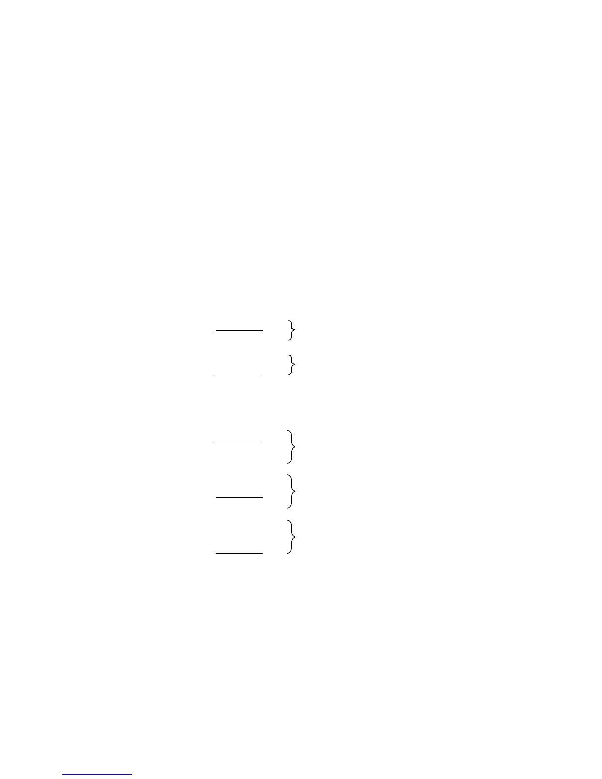
WF 723 C
Positioning Module
Programming Guide
Basic Definitions
Program Execution /
Subroutines
Programming of
Traversing Blocks
M-Functions
with Special Function
2
3
4
5
Valid for firmware V1.2
Edition April 1997
Tool Offsets
Programming in S5 Format
Appendix
6
7
8
Page 3

Note
Because of clear arrangement, this documentation does not inform about all details of all
types of the product. Therefore, it cannot take into account all possible cases of
installations, operation and maintenance.
If you require additional information or have special questions, please seek further
particulars from your local SIEMENS office.
The content of this documentation is not part of an earlier or existing agreement,
acceptance or legal matter. All obligations by SIEMENS are set in the corresponding
sales contract which also contains the complete and single valid settlement. The
contract guarantee will not be enlarged or limited by this documentation.
BERO, SIMATIC, SIMODRIVE, SINEC, SINUMERIK, STEP are registered trade marks of Siemens.
The remaining designations contained in this programming guide may be trade marks whose use
through third parties for their own purposes may infringe the rights of the owners of the mark.
Subject to technical changes.
The reproduction, transmission or use of this document or of its
contents is not permitted without express written authority.
Offenders will be liable for damages. All rights, including rights
supplied by patent grant or registration of a utility model or
design, are reserved.
©
Siemens AG 1997 All Rights Reserved
Page 4

Contents
1 Preface
2 Basic Definitions
2.1 Overview . . . . . . . . . . . . . . . . . . . . . . . . . . . . . . . . . . . . . . . 2 – 1
2.2 Traversing program . . . . . . . . . . . . . . . . . . . . . . . . . . . . . . . 2 – 1
2.2.1 Channel structure . . . . . . . . . . . . . . . . . . . . . . . . . . . . . . . . . 2 – 2
2.2.2 Feed axes in the traversing program . . . . . . . . . . . . . . . . . . . . 2 – 3
2.2.3 Synchronism in the traversing program . . . . . . . . . . . . . . . . . . 2 – 3
2.2.4 Coordination of the control signals in the traversing program . . . 2 – 3
2.2.5 Memory capacity . . . . . . . . . . . . . . . . . . . . . . . . . . . . . . . . . 2 – 3
2.2.6 Program number / subroutine number . . . . . . . . . . . . . . . . . . . 2 – 3
2.2.7 Program structure . . . . . . . . . . . . . . . . . . . . . . . . . . . . . . . . . 2 – 4
2.3 Traversing block . . . . . . . . . . . . . . . . . . . . . . . . . . . . . . . . . . 2 – 4
2.3.1 Block structure . . . . . . . . . . . . . . . . . . . . . . . . . . . . . . . . . . . 2 – 4
2.3.2 Block number . . . . . . . . . . . . . . . . . . . . . . . . . . . . . . . . . . . . 2 – 5
2.3.3 Axis assignment . . . . . . . . . . . . . . . . . . . . . . . . . . . . . . . . . . 2 – 5
2.3.4 G-functions . . . . . . . . . . . . . . . . . . . . . . . . . . . . . . . . . . . . . 2 – 6
2.3.5 Path information (position) . . . . . . . . . . . . . . . . . . . . . . . . . . . 2 – 8
2.3.6 Speed . . . . . . . . . . . . . . . . . . . . . . . . . . . . . . . . . . . . . . . . . 2 – 8
2.3.7 M-functions . . . . . . . . . . . . . . . . . . . . . . . . . . . . . . . . . . . . . 2 – 9
2.3.8 Tool offset number . . . . . . . . . . . . . . . . . . . . . . . . . . . . . . . 2 – 10
2.3.9 Dwell time . . . . . . . . . . . . . . . . . . . . . . . . . . . . . . . . . . . . . 2 – 10
3 Program Execution / Subroutines
3.1 Program execution . . . . . . . . . . . . . . . . . . . . . . . . . . . . . . . . 3 – 1
3.2 Skippable blocks . . . . . . . . . . . . . . . . . . . . . . . . . . . . . . . . . 3 – 2
3.3 Subroutines . . . . . . . . . . . . . . . . . . . . . . . . . . . . . . . . . . . . . 3 – 3
3.3.1 Subroutine call . . . . . . . . . . . . . . . . . . . . . . . . . . . . . . . . . . . 3 – 3
3.3.2 Subroutine execution . . . . . . . . . . . . . . . . . . . . . . . . . . . . . . 3 – 3
3.3.3 Programming guidelines . . . . . . . . . . . . . . . . . . . . . . . . . . . . 3 – 4
3.4 Block search forwards . . . . . . . . . . . . . . . . . . . . . . . . . . . . . . 3 – 5
3.4.1 Automatic block search . . . . . . . . . . . . . . . . . . . . . . . . . . . . . 3 – 5
3.4.2 Manual block search . . . . . . . . . . . . . . . . . . . . . . . . . . . . . . . 3 – 6
3.4.2.1 Entry point in the main program . . . . . . . . . . . . . . . . . . . . . . . 3 – 6
3.4.2.2 Entry point in subroutine level 1 . . . . . . . . . . . . . . . . . . . . . . . 3 – 6
3.4.2.2 Entry point in subroutine level 2 . . . . . . . . . . . . . . . . . . . . . . . 3 – 7
3.4.3 Conditions of block search forwards . . . . . . . . . . . . . . . . . . . . 3 – 7
3.4.4 Program start after activation of block search forwards . . . . . . . 3 – 7
. . . . . . . . . . . . . . . . . . . . . . . . . . . . . . . . . . . . . . 1 – 1
. . . . . . . . . . . . . . . . . . . . . . . . . . . . . . 2 – 1
. . . . . . . . . . . . . . 3 – 1
4 Programming of Traversing Blocks
4.1 Coordinate system and reference points . . . . . . . . . . . . . . . . . 4 – 1
4.2 Dimensions G90, G91 . . . . . . . . . . . . . . . . . . . . . . . . . . . . . . 4 – 2
4.2.1 Linear axis . . . . . . . . . . . . . . . . . . . . . . . . . . . . . . . . . . . . . . 4 – 2
4.2.2 Rotary axis, shortest distance G68 . . . . . . . . . . . . . . . . . . . . . 4 – 3
4.3 Dwell time G04 . . . . . . . . . . . . . . . . . . . . . . . . . . . . . . . . . . 4 – 4
4.4 Zero point offset G53, G54 to G59 . . . . . . . . . . . . . . . . . . . . . 4 – 5
4.5 Chaining with rapid traverse G76 . . . . . . . . . . . . . . . . . . . . . . 4 – 7
4.6 Chaining with axis velocity G77 . . . . . . . . . . . . . . . . . . . . . . . 4 – 8
4.7 Interpolation with rapid traverse G00 . . . . . . . . . . . . . . . . . . . 4 – 10
4.8 Interpolation with path velocity G01 . . . . . . . . . . . . . . . . . . . 4 – 11
. . . . . . . . . . . . . 4 – 1
Page 5

4.9 Synchronism . . . . . . . . . . . . . . . . . . . . . . . . . . . . . . . . . . . 4 – 13
4.9.1 Permanent synchronism . . . . . . . . . . . . . . . . . . . . . . . . . . . 4 – 13
4.9.2 Selectable synchronism . . . . . . . . . . . . . . . . . . . . . . . . . . . . 4 – 13
4.9.3 Tracking synchronism (G79 . . . . . . . . . . . . . . . . . . . . . . . . . 4 – 14
4.9.4 Synchronism in combination with interpolation and chaining . . 4 – 15
4.10 Collision monitoring (G96, G97) . . . . . . . . . . . . . . . . . . . . . . 4 – 16
4.10.1 Specifying a deceleration value . . . . . . . . . . . . . . . . . . . . . . 4 – 16
4.10.2 Specifying a rapid input . . . . . . . . . . . . . . . . . . . . . . . . . . . . 4 – 16
4.10.3 Collision monitoring - Example . . . . . . . . . . . . . . . . . . . . . . . 4 – 17
4.11 Block transitions . . . . . . . . . . . . . . . . . . . . . . . . . . . . . . . . . 4 – 19
4.11.1 Maximum loop-over G64 . . . . . . . . . . . . . . . . . . . . . . . . . . . 4 – 19
4.11.2 Exact stop G60 . . . . . . . . . . . . . . . . . . . . . . . . . . . . . . . . . . 4 – 22
4.11.3 Loop-over window 1 or 2 (G66, G67) . . . . . . . . . . . . . . . . . . 4 – 25
4.11.4 Path-dependent chaining (G63) . . . . . . . . . . . . . . . . . . . . . . 4 – 27
4.11.5 Block transitions with different coupling types . . . . . . . . . . . . 4 – 30
4.11.6 M-functions . . . . . . . . . . . . . . . . . . . . . . . . . . . . . . . . . . . . 4 – 31
4.11.6.1 Output of M-functions during positioning . . . . . . . . . . . . . . . . 4 – 31
4.11.6.2 Output of M-functions before positioning . . . . . . . . . . . . . . . . 4 – 32
4.11.6.3 Output of M-functions after positioning . . . . . . . . . . . . . . . . . 4 – 33
4.11.7 External block change G50, G51) . . . . . . . . . . . . . . . . . . . . . 4 – 34
4.11.8 Flying actual-value setting G87, G88, G89 . . . . . . . . . . . . . . 4 – 36
4.11.9 Program-dependent external read-in enable (G99) . . . . . . . . . 4 – 38
4.11.10 Acceleration override G30 to G39 . . . . . . . . . . . . . . . . . . . . . 4 – 39
5 M-Functions with Special Function
5.1 Stop at block end M00 . . . . . . . . . . . . . . . . . . . . . . . . . . . . . 5 – 1
5.2 Continuous loop M18 . . . . . . . . . . . . . . . . . . . . . . . . . . . . . . 5 – 1
5.3 Subroutine end M17/M29 . . . . . . . . . . . . . . . . . . . . . . . . . . . . 5 – 2
5.4 Program end M02/M30 . . . . . . . . . . . . . . . . . . . . . . . . . . . . . 5 – 2
6 Tool Offsets
6.1 Tool offset G43, G44 . . . . . . . . . . . . . . . . . . . . . . . . . . . . . . 6 – 1
6.2 Tool offset memory . . . . . . . . . . . . . . . . . . . . . . . . . . . . . . . . 6 – 2
6.3 Variants of tool offset . . . . . . . . . . . . . . . . . . . . . . . . . . . . . . 6 – 3
6.3.1 Tool length offset . . . . . . . . . . . . . . . . . . . . . . . . . . . . . . . . . 6 – 3
6.3.2 Tool length wear . . . . . . . . . . . . . . . . . . . . . . . . . . . . . . . . . . 6 – 4
6.4 Direction of tool length offset . . . . . . . . . . . . . . . . . . . . . . . . . 6 – 5
7 Programming in S5 Format
8 Appendix
8.1 Abbreviations . . . . . . . . . . . . . . . . . . . . . . . . . . . . . . . . . . . . 8 – 1
8.2 Index . . . . . . . . . . . . . . . . . . . . . . . . . . . . . . . . . . . . . . . . . . 8 – 2
. . . . . . . . . . . . . . . . . . . . . . . . . . . . . . . . . . 6 – 1
. . . . . . . . . . . . . . . . . . . . 7 – 1
. . . . . . . . . . . . . . . . . . . . . . . . . . . . . . . . . . . . . 8 – 1
. . . . . . . . . . . . . 5 – 1
Page 6

04.97 Preface
1 Preface
What information is to be
found in this manual?
For whom is this manual
intended?
What prior knowledge is
needed?
Finding your way about
the manual.
This manual gives you detailed information about the
programming of the positioning module. The programming of
functions is described in the context. Examples and practical
tips provide improvement for your own cases of application.
See the end of this manual for application area, contents and
target group of this WF 723 C manual.
This programming guide is intended for machine design
engineers who plan to use the WF 723 C and have to observe
the relevant guidelines.
The target group must be qualified according to the definitions
on page 1-2.
Beside this programming guide, all general safety regulations,
regulations of the VDE and the national safety rules must be
observed.
This programming guide is divided up into the sections:
➤ Basic description
➤ Programming
Each chapter of this programming guide is a self-contained unit.
In the appendix, you will find an alphabetic index.
Improvements required? Please do not hesitate to inform us if you have any suggestions
or improvements, using the form at the end of this manual. We
will try to consider your suggestions in the next edition.
©
Siemens AG 1997 All Rights Reserved 6ZB5 440-0VU02
WF 723 C (Programming Guide)
1 – 1
Page 7
Preface 04.97
Definitions/
Explanation of Terms
Qualified personnel
Attention
Caution
Persons being in charge of installation, mounting and operating
the product must be qualified by e.g.:
➤ Training, instruction or permission to switch, earth and mark
and electrical circuits ans devices according to standard
safety regulations.
➤ Training and instruction of care and use of appropriate safety
equipment according to standard safety regulations.
➤ Training in first aid.
ATTENTION
Slight injury or damage to property may
occur if the prescribed precautionary
measures are not observed.
CAUTION
Danger
Death, grievous bodily harm or considerable
damage to property may occur if the
prescribed precautionary measured are not
observed.
DANGER
Death, grievous bodily harm or considerable
damage to property will occur if the
prescribed precautionary measures are not
observed.
1 – 2 ©
Siemens AG 1997 All Rights Reserved 6ZB5 440-0VU02
WF 723 C (Programming Guide)
Page 8
04.97 Preface
aaaaaaa
a
aaaaaaa
a
aaaaaaa
a
aaaaaaa
a
aaaaaaa
a
aaaaaaa
Notes
Cross references
Necessary calculations
Changes as against the
former edition
This symbol draws your attention to important
and useful information.
This symbol refers to certain information in a
manual.
The data marked with this symbol must be
calculated and not determined empirically.
The edition of June 1996 was revised on the following pages:
2-7
4-27 to 4-30
7-5, 7-12
©
Siemens AG 1997 All Rights Reserved 6ZB5 440-0VU02
WF 723 C (Programming Guide)
1 – 3
Page 9

Preface 04.97
1 – 4 ©
Siemens AG 1997 All Rights Reserved 6ZB5 440-0VU02
WF 723 C (Programming Guide)
Page 10

04.97 Basic Definitions
2 Basic Definitions
2.1 Overview
The WF 723 C positions up to three position-controlled axes, both independent of each other
and coordinated and combined. functions like linear interpolation, synchronism and chaining, in
addition to simple point-to-point positioning processes, are an important part of today's
automation tasks. Further possibilities, such as flying actual-value setting, external block
change, the use of tool offsets, zero point offsets and the output of M-functions, are also
offered by the WF 723 C module.
These functions are applied in:
• Handling devices
• Portals
• Press feeding devices
• Wood working machines
• Storage and retrieval units
• Special machines
• Packaging machines
Furthermore, the roll feed function is integrated in the WF 723 C. The roll feed serves for fast
and exact positioning of highly dynamic conveyors
This functions is applied in:
• Sheet metal working machines
• Packaging and filling machines
To make all these possibilities available for the user, the programming of traversing programs
is the means to formulate information and translate it into a language understandable to the
WF module.
2.2 Traversing program
The program structure is defined according to DIN 66025. A traversing program consists of a
sequence of up to 200 traversing blocks and is assigned to a programm number.
The traversing program is situated in the RAM memory of the WF module and is buffered by
the SIMATIC S5.
In case of a RAM memory failure the RAM memory contents of the
WF module is lost.
The programming examples are displayed according to DIN 66025. Inputs
via COM 723 are entered in this format. The programs are stored in the
SIMATIC S5 and the WF in S5 format. See a comparison of DIN format and
S5 format in the chapter ”programming in S5 format”.
©
Siemens AG 1997 All Rights Reserved 6ZB5 440-0VU02
WF 723 C (Programming Guide)
2 – 1
Page 11
Basic Definitions 04.97
2.2.1 Channel structure
In principle, the WF 723 C possesses 3 channels, in accordance with its 3 axes. Therefore, it
is possible to have all axes execute their own traversing programs simultaneously. for this
purpose, however, the traversing program must only contain information for the related axis.
As all axes are treated as equivalent, all axes are master axes.
If in one traversing program the information of mor than one axis is formulated, this information
belongs to a channel. Coordination in the form of program preselection and start is always
carried out by the master axis. The other axes appearing in the traversing program are slave
axes.
Example:
a) Each axis with its own program
Program 10 ➯ axis A* ➯ master axis: channel 1
Program 20 ➯ axis B* ➯ master axis: channel 2
Program 30 ➯ axis C* ➯ master axis: channel 3
b) 2 axes in one program, 1 axis with its own program
Program 10 ➯ axis A* ➯ master axis
➯ axis C* ➯ slave axis
or
➯ axis A* ➯ slave axis
➯ axis C* ➯ master axis
Program 20 ➯ axis B* ➯ master axis: channel 2
c) 3 axes in one program
Program 10 ➯ axis A* ➯ master axis
➯ axis B* ➯ slave axis
➯ axis C* ➯ slave axis
or
➯ axis A* ➯ slave axis
➯ axis B* ➯ master axis
➯ axis C* ➯ slave axis
or
➯ axis A* ➯ slave axis
➯ axis B* ➯ slave axis
➯ axis C* ➯ master axis
channel 1
channel 1
channel 1
channel 1
channel 1
2 – 2 ©
Siemens AG 1997 All Rights Reserved 6ZB5 440-0VU02
WF 723 C (Programming Guide)
Page 12

04.97 Basic Definitions
2.2.2 Feed axes in the traversing program
If the axis is used as a feed axis, the traversing block must contain exclusively the information
of this one feed axis. Furthermore, the traversing program must be started in this axis.
If two or three feed axes are operated, these must be supplied in separate channels, i.e. with
their own traversing programs, with the exception of permanent synchronism (see channel
structure, example a).
2.2.3 Synchronism in the traversing program
Axes as well as feed axes can be operated in permanent synchronism. The coupling of the
axes is not effected by the traversing program, but through machine data. The machine data
determine which axis is the master axis and which is the slave axis for the synchronism. Only
the master axis has to be programmed in the traversing program. The slave axes "follow"
automatically.
2.2.4 Coordination of the control signals in the traversing program
As the master axis is the coordinating axis, program preselection and start are effected in this
axis. In addition, the operating mode "automatic" or "single block" must be preset in the
master axis. To operate the slave axes contained in the traversing program as slave axes, they
must be switched to the "slave" operating mode, otherwise the WF 723 C will not start
program execution.
For further details on the operation of the control signals, see the
description of functions, chapter "control and acknowledgment signals"
and the operating mode "automatic, single block and slave".
2.2.5 Memory capacity
Up to 200 programs or subroutines can be stored at the same time in the program memory.
The sum of traversing blocks must not exceed 1000 for S5 format. One traversing block in DIN
format may consist of several traversing blocks in S5 format.
2.2.6 Program number / Subroutine number
The figures 1 to 200 are possible program or subroutine numbers.
©
Siemens AG 1997 All Rights Reserved 6ZB5 440-0VU02
WF 723 C (Programming Guide)
2 – 3
Page 13
Basic Definitions 04.97
2.2.7 Program structure
A traversing program consists of a number of traversing blocks, which are processed in
ascending order of the block numbers. Start and end of the program need not be marked. The
first traversing block is automatically the start of the program and the last traversing block, the
end of the program. For better readability of the programs, special M-functions which
according to DIN 66025 effect program end (M02, M30) or subroutine end (M17, M29), can be
used.
In principle, subroutines do not differ from main programs, as they become subroutines only
when called from a traversing program, i.e. subroutines can also be run as main programs.
2.3 Traversing blocks
A traversing block contains all data to execute a processing step, e.g. positioning, dwelling or
output of switching functions.
2.3.1 Block structure
A traversing block consists of:
• Character for block start
• Block number
• Number of words containing data for the execution of a processing step
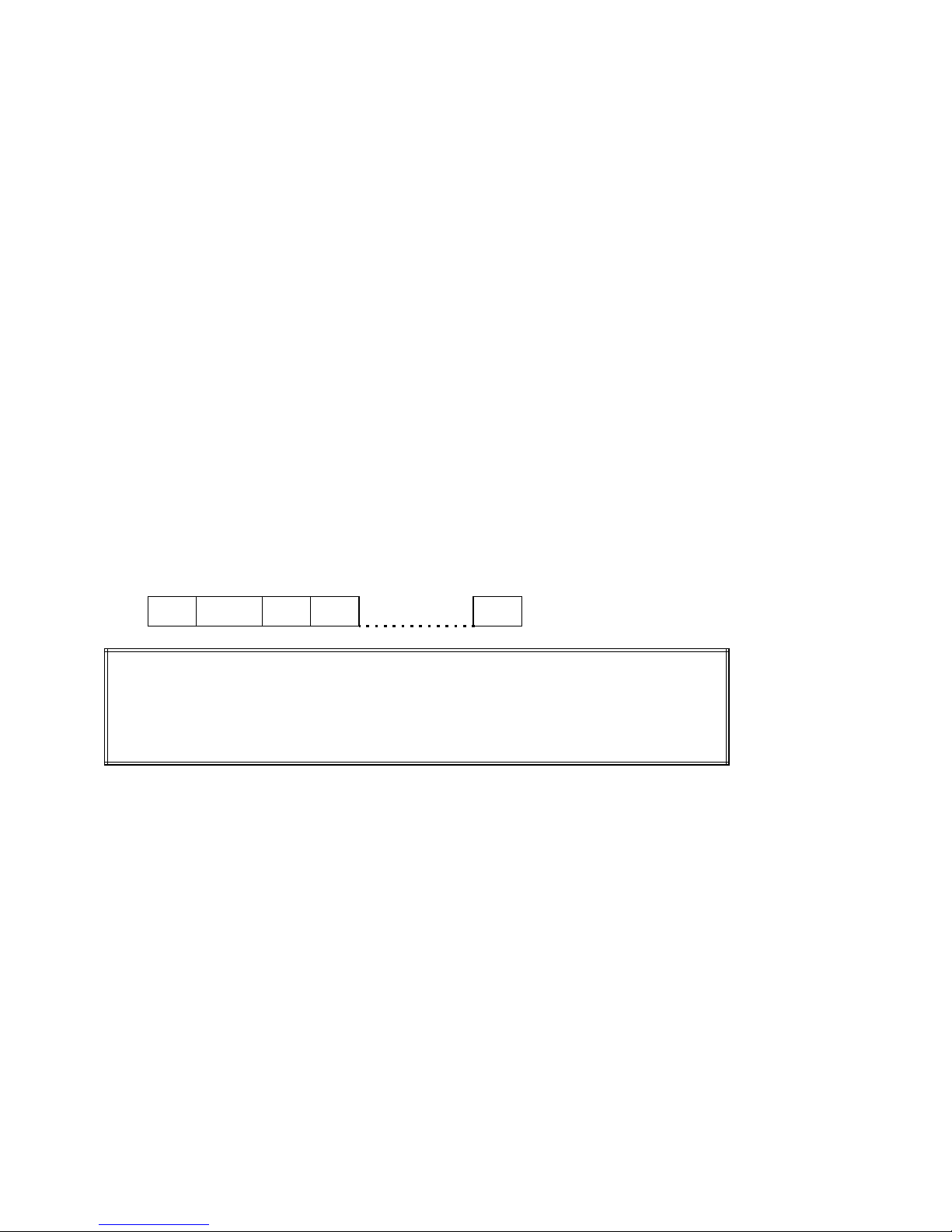
N Block No. Word Word Word
Programming:
N10 G.. X.. Y.. Z.. F.. M.. D..
N20 L.. P..
/ N30 ...
/ . . . . . . . . . . . Skip identifier for skip block
N . . . . . . . . . . Block number
G . . . . . . . . . . G-functions
X, Y, Z . . . . . . Path information of axes (preferably linear axes)
A, B, C . . . . . . Path information of axes (preferably rotary axes)
XY, XZ, AYX, etc. Path information of syncronous axes (selectable aynchronism), the first
axis being the master axis of the synchronism).
Any combinations of axes A, B, C, X , Y, Z are possible, with 2 or 3 digits.
X . . . . . . . . . . Indication of the dwell time
F . . . . . . . . . . Path velocity for interpolation
FX, FY, FZ, etc. Axis velocity for chanining
M . . . . . . . . . . M-function (machine function)
D . . . . . . . . . . Tool offset number
L . . . . . . . . . . Subroutine number
P . . . . . . . . . . Number of loops
2 – 4 ©
Siemens AG 1997 All Rights Reserved 6ZB5 440-0VU02
WF 723 C (Programming Guide)
Page 14
04.97 Basic Definitions
aaaaaaaaaaaaaaaaaaaaaaaaaaaaaaaaaaaaaaaaaaaaaaaaaaaaaaaaaaaaaaaaaaaaaaaaaaaaaaaaaaaaaaaaaaaaaaaaaaaaaaaaaaaaaaa
a
a
a
a
a
a
a
a
a
a
a
aaaaaaaaaaaaa
a
a
a
a
a
a
a
a
a
a
a
a
a
a
a
a
a
a
a
a
a
a
a
a
a
a
a
a
a
a
a
a
a
a
a
a
a
a
A word is an element of a traversing block and consists of an address character and a
sequence of digits. The address character is an alphanumerical sequence of digits. The
sequence of digits may have a sign and a decimal point. The sign must be located between
the address character and the sequence of digits, a positive sign is not entered. No blank is
admitted between the address and the value.
Examples:
Address
X
1.000
Word
Value
Y
-2.000
Word
M1=
Word
10
2.3.2 Block number
Programming:
N10 G90 G43 X100.000 F4000.00 M1=10 M2=11 M3=12 D1
Block numbers from 1 to 200 are admitted. The blocks may be assigned to any number but
make sure that the program is executed in ascending order of the block numbers. It is
recommended to define the block numbers in steps of five (5, 10, 15 ...) to be able to insert
further blocks subsequently.
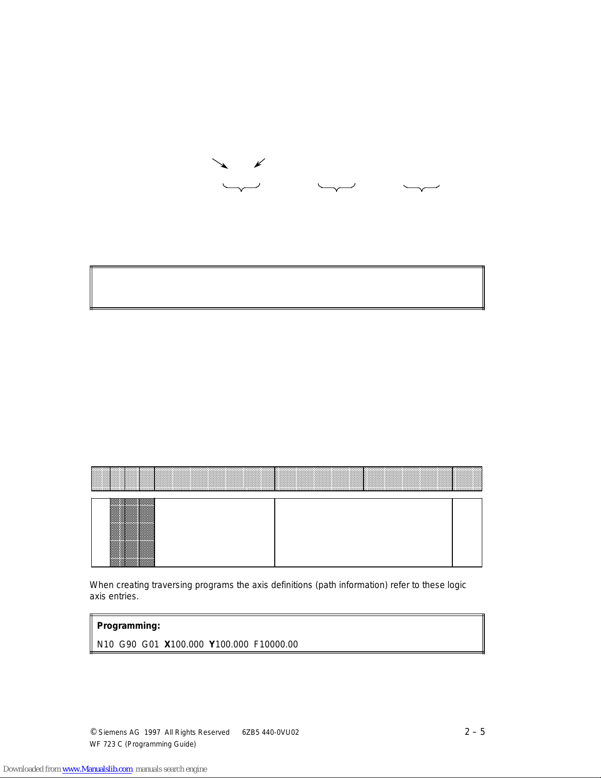
2.3.3 Axis assignment
The physical hardware axes A*, B* and C* are situated on the WF 723 C module. A logic name
(X, Y, Z for linear axes and A, B, C for rotary axes) can be assigned to each hardware axis by
means of machine data 38.
aaaaaaaaaaaaaaaaaaaaaaaaaaaaaaaaaaaaaaaaaaaaaaaaaaaaaaaaaaaaaaaaaaaaaaaaaaaaaaaaaaaaaaaaaaaaaaaaaaaaaaaaaaaaa
MD-
aaaaaaaaaaaaaaaaaaaaaaaaaaaaaaaaaaaaaaaaaaaaaaaaaaaaaaaaaaaaaaaaaaaaaaaaaaaaaaaaaaaaaaaaaaaaaaaaaaaaaaaaaaaaa
aaaaaaaaaaaaaaaaaaaaaaaaaaaaaaaaaaaaaaaaaaaaaaaaaaaaaaaaaaaaaaaaaaaaaaaaaaaaaaaaaaaaaaaaaaaaaaaaaaaaaaaaaaaaa
I SSI W
aaaaaaaaaaaaaaaaaaaaaaaaaaaaaaaaaaaaaaaaaaaaaaaaaaaaaaaaaaaaaaaaaaaaaaaaaaaaaaaaaaaaaaaaaaaaaaaaaaaaaaaaaaaaa
No.
aaaaaaaaaaaaaaaaaaaaaaaaaaaaaaaaaaaaaaaaaaaaaaaaaaaaaaaaaaaaaaaaaaaaaaaaaaaaaaaaaaaaaaaaaaaaaaaaaaaaaaaaaaaaa
aaaaaaaaaaa
aaaaaaaaaaa
aaaaaaaaaaa
aaaaaaaaaaa
aaaaaaaaaaa
aaaaaaaaaaa
aaaaaaaaaaa
aaaaaaaaaaa
aaaaaaaaaaa
aaaaaaaaaaa
38
aaaaaaaaaaa
aaaaaaaaaaa
aaaaaaaaaaa
aaaaaaaaaaa
aaaaaaaaaaa
aaaaaaaaaaa
aaaaaaaaaaa
aaaaaaaaaaa
aaaaaaaaaaa
Axis assignment
Designation
Lower limit Upper limit
1 : X-axis
2 : Y-axis
3 : Z-axis
4 : A-axis
5 : B-axis
6 : C-axis
When creating traversing programs the axis definitions (path information) refer to these logic
axis entries.
Programming:
N10 G90 G01 X100.000 Y100.000 F10000.00
©
Siemens AG 1997 All Rights Reserved 6ZB5 440-0VU02
WF 723 C (Programming Guide)
a
a
a
Unit
a
a
––
2 – 5
Page 15
Basic Definitions 04.97
Example 1: Machine tool with 3 linear axes
Hardware axis A*: Axis X ➯ MD 38 = 1
Hardware axis B*: Axis Y ➯ MD 38 = 2
Hardware axis C*: Axis Z ➯ MD 38 = 3
Example 2: Machine tool with 2 linear axes and 1 rotary axis
Hardware axis A*: Axis X ➯ MD 38 = 1
Hardware axis B*: Axis A ➯ MD 38 = 4
Hardware axis C*: Axis Y ➯ MD 38 = 2
You may assign linear and rotary axes as required. Wrong axis assignments
are programming errors and may lead to incorrect movements of the axes.
It is not allowed to assign one logic axis twice to one module.
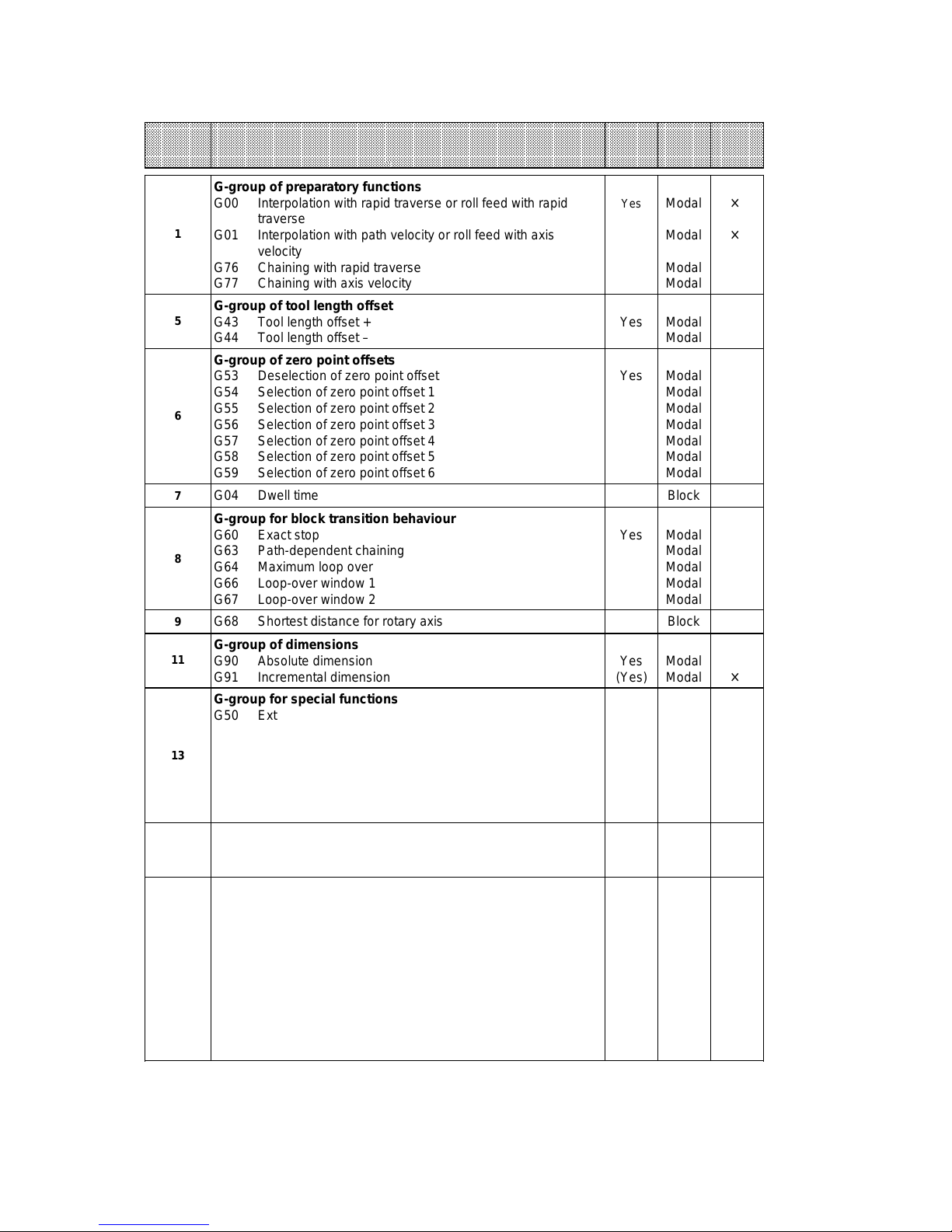
2.3.4 G-functions
On the one hand, the type of movement is defined via the G-functions, on the other hand, they
serve to call offsets, displacements, and special functions.
The G-functions are divided into G-groups according to their definitions. In each G-group there
is a switch-on status or basic position, i.e. the G-function is active without selection.
Example: G00 - interpolation with rapid traverse for the first G-group.
The effectiveness of G-functions is characterised by ”modal” or ”block (local)”. G-functions
effective block by block are only effective in the programmed block. Modally effective Gfunctions are active until they are replaced by other G-functions of the same G-group.
Example: G77 - chaining with axis velocity deselects G76 - chaining with rapid traverse.
Programming:
N10 G90 G43 X100.000 F4000.00 M1=10 M2=11 M3=13 D1
Several G-functions may be defined in one traversing block. Each program is a self-contained
unit, separated from other traversing programs. Therefore, all G-groups are in basic position at
the beginning of the program and brought in the required position if necessary.
For roll feed, only a limited number of G-functions are admissible
(see table G-functions).
2 – 6 ©
Siemens AG 1997 All Rights Reserved 6ZB5 440-0VU02
WF 723 C (Programming Guide)
Page 16
04.97 Basic Definitions
aaaaaaaaaaaaaaaaaaaaaaaaaaaaaaaaaaaaaaaaaaaaaaaaaaaaaaaaaaaaaaaaaaaaaaaaaaaaaaaaaaaaaaaaaaaaaaaaaaaaaaaaaaaaaaa
a
a
a
a
a
a
a
a
a
a
a
a
a
a
a
aaaaaaaaaaaaaaaaaaaaaaaaaaaaaaaaaaaaaaaaaaaaaaaaaaaaaaaaaaaaaaaaaaaaaaaaaaaaaaaaaaaaaaaaaaaaaaaaaaaaaaaaaaaaa
aaaaaaaaaaaaaaaaaaaaaaaaaaaaaaaaaaaaaaaaaaaaaaaaaaaaaaaaaaaaaaaaaaaaaaaaaaaaaaaaaaaaaaaaaaaaaaaaaaaaaaaaaaaaa
aaaaaaaaaaaaaaaaaaaaaaaaaaaaaaaaaaaaaaaaaaaaaaaaaaaaaaaaaaaaaaaaaaaaaaaaaaaaaaaaaaaaaaaaaaaaaaaaaaaaaaaaaaaaa
aaaaaaaaaaaaaaaaaaaaaaaaaaaaaaaaaaaaaaaaaaaaaaaaaaaaaaaaaaaaaaaaaaaaaaaaaaaaaaaaaaaaaaaaaaaaaaaaaaaaaaaaaaaaa
DIN group
aaaaaaaaaaaaaaaaaaaaaaaaaaaaaaaaaaaaaaaaaaaaaaaaaaaaaaaaaaaaaaaaaaaaaaaaaaaaaaaaaaaaaaaaaaaaaaaaaaaaaaaaaaaaa
aaaaaaaaaaaaaaaaaaaaaaaaaaaaaaaaaaaaaaaaaaaaaaaaaaaaaaaaaaaaaaaaaaaaaaaaaaaaaaaaaaaaaaaaaaaaaaaaaaaaaaaaaaaaa
aaaaaaaaaaaaaaaaaaaaaaaaaaaaaaaaaaaaaaaaaaaaaaaaaaaaaaaaaaaaaaaaaaaaaaaaaaaaaaaaaaaaaaaaaaaaaaaaaaaaaaaaaaaaa
G-function
Basic
position
active
Effectiveness
Roll
feed
G-group of preparatory functions
G00 Interpolation with rapid traverse or roll feed with rapid
Modal
×
Yes
traverse
1
G01 Interpolation with path velocity or roll feed with axis
Modal
×
velocity
G76 Chaining with rapid traverse
G77 Chaining with axis velocity
Modal
Modal
G-group of tool length offset
5
G43 Tool length offset +
G44 Tool length offset –
Yes Modal
Modal
G-group of zero point offsets
G53 Deselection of zero point offset
G54 Selection of zero point offset 1
G55 Selection of zero point offset 2
6
G56 Selection of zero point offset 3
G57 Selection of zero point offset 4
G58 Selection of zero point offset 5
G59 Selection of zero point offset 6
7
G04 Dwell time Block
Yes Modal
Modal
Modal
Modal
Modal
Modal
Modal
G-group for block transition behaviour
G60 Exact stop
G63 Path-dependent chaining
8
G64 Maximum loop over
G66 Loop-over window 1
G67 Loop-over window 2
9
G68 Shortest distance for rotary axis Block
Yes Modal
Modal
Modal
Modal
Modal
G-group of dimensions
11
G90 Absolute dimension
G91 Incremental dimension
Yes
(Yes)
Modal
Modal
×
G-group for special functions
G50 External block change with absoute dimension
G51 External block change with incremental dimension
G79 Synchronization
13
G87 Flying actual-value setting - deselction
G88 Flying actual-value setting / continuous rotation –
G89 Flying actual-value setting / continuous rotation +
G99 Program-dependent external read-in enable
Block
Block
Block
Block
Block
Block
Block
×
G-group for collision monitoring
14
G96 Selection collision monitoring
G97 Deselection collision monitoring Yes
Modal
Modal
G-group for acceleration/braking
G30 100% override acceleration/braking
G31 10% override acceleration/braking
G32 20% override acceleration/braking
G33 30% override acceleration/braking
16
G34 40% override acceleration/braking
G35 50% override acceleration/braking
G36 60% override acceleration/braking
G37 70% override acceleration/braking
G38 80% override acceleration/braking
G39 90% override acceleration/braking
Yes Modal
Modal
Modal
Modal
Modal
Modal
Modal
Modal
Modal
Modal
×
×
×
×
×
×
×
×
×
×
a
a
a
a
a
a
a
©
Siemens AG 1997 All Rights Reserved 6ZB5 440-0VU02
WF 723 C (Programming Guide)
2 – 7
Page 17
Basic Definitions 04.97
aaaaaaaaaaaaaaaaaaaaaaaaaaaaaaaaaaaaaaaaaaaaaaaaaaaaaaaaaaaaaaaaaaaaaaaaaaaaaaaaaaaaaaaaaaaaaaaaaaa
a
a
a
a
a
a
a
a
a
a
a
a
aaaaaaaaaaaaaaaaaaaaaaaaaaaaaaaaaaaaaaaaaaaaaaaaaaaaaaaaaaaaaaaaaaaaaaaaaaaaaaaaaaaaaaaaaaaaaaaaaaa
a
a
a
a
a
a
a
a
a
a
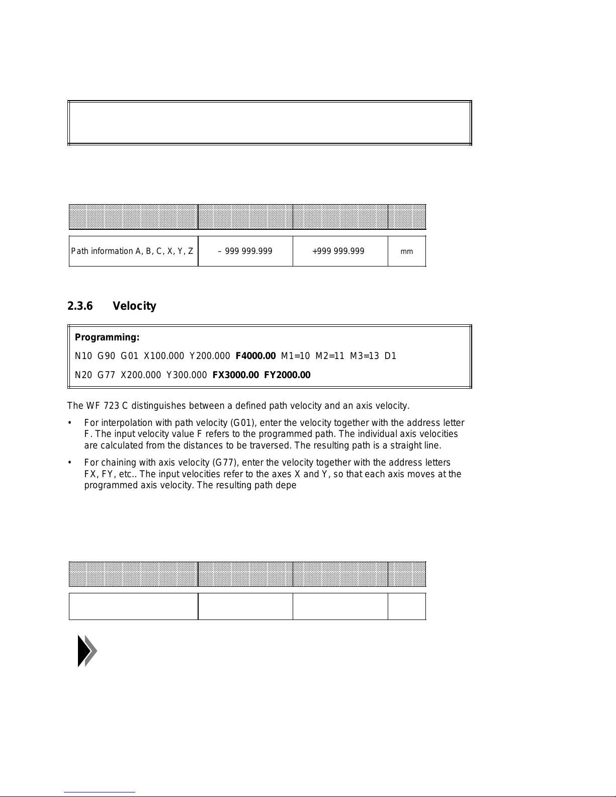
2.3.5 Path information (position)
Programming:
N10 G90 G43 G01 Z100.000 F4000.00 M1=10 M2=11 M3=13 D1
The path information is defined by the address character for the axis designation (X, Y, Z ...)
and the position value. A negative or positive sign may be entered with the path information.
When entering positive values, no sign need be entered.
aaaaaaaaaaaaaaaaaaaaaaaaaaaaaaaaaaaaaaaaaaaaaaaaaaaaaaaaaaaaaaaaaaaaaaaaaaaaaaaaaaaaaaaaaaaaaaaaa
aaaaaaaaaaaaaaaaaaaaaaaaaaaaaaaaaaaaaaaaaaaaaaaaaaaaaaaaaaaaaaaaaaaaaaaaaaaaaaaaaaaaaaaaaaaaaaaaa
aaaaaaaaaaaaaaaaaaaaaaaaaaaaaaaaaaaaaaaaaaaaaaaaaaaaaaaaaaaaaaaaaaaaaaaaaaaaaaaaaaaaaaaaaaaaaaaaa
Designation
aaaaaaaaaaaaaaaaaaaaaaaaaaaaaaaaaaaaaaaaaaaaaaaaaaaaaaaaaaaaaaaaaaaaaaaaaaaaaaaaaaaaaaaaaaaaaaaaa
aaaaaaaaaaaaaaaaaaaaaaaaaaaaaaaaaaaaaaaaaaaaaaaaaaaaaaaaaaaaaaaaaaaaaaaaaaaaaaaaaaaaaaaaaaaaaaaaa
aaaaaaaaaaaaaaaaaaaaaaaaaaaaaaaaaaaaaaaaaaaaaaaaaaaaaaaaaaaaaaaaaaaaaaaaaaaaaaaaaaaaaaaaaaaaaaaaa
Lower limit Upper limit
Unit
Path information A, B, C, X, Y, Z – 999 999.999 +999 999.999
mm
2.3.6 Velocity
Programming:
N10 G90 G01 X100.000 Y200.000 F4000.00 M1=10 M2=11 M3=13 D1
N20 G77 X200.000 Y300.000 FX3000.00 FY2000.00
The WF 723 C distinguishes between a defined path velocity and an axis velocity.
• For interpolation with path velocity (G01), enter the velocity together with the address letter
F. The input velocity value F refers to the programmed path. The individual axis velocities
are calculated from the distances to be traversed. The resulting path is a straight line.
• For chaining with axis velocity (G77), enter the velocity together with the address letters
FX, FY, etc.. The input velocities refer to the axes X and Y, so that each axis moves at the
programmed axis velocity. The resulting path depends on the distances to be traversed
and on the axis velocities.
Both during interpolation and during chaining, the WF 723 C monitors that no axis traverses at
a velocity higher than its own traversing velocity - maximally (MD 31). All velocity values are
modally effective.
aaaaaaaaaaaaaaaaaaaaaaaaaaaaaaaaaaaaaaaaaaaaaaaaaaaaaaaaaaaaaaaaaaaaaaaaaaaaaaaaaaaaaaaaaaaaaaaaa
aaaaaaaaaaaaaaaaaaaaaaaaaaaaaaaaaaaaaaaaaaaaaaaaaaaaaaaaaaaaaaaaaaaaaaaaaaaaaaaaaaaaaaaaaaaaaaaaa
aaaaaaaaaaaaaaaaaaaaaaaaaaaaaaaaaaaaaaaaaaaaaaaaaaaaaaaaaaaaaaaaaaaaaaaaaaaaaaaaaaaaaaaaaaaaaaaaa
Designation
aaaaaaaaaaaaaaaaaaaaaaaaaaaaaaaaaaaaaaaaaaaaaaaaaaaaaaaaaaaaaaaaaaaaaaaaaaaaaaaaaaaaaaaaaaaaaaaaa
aaaaaaaaaaaaaaaaaaaaaaaaaaaaaaaaaaaaaaaaaaaaaaaaaaaaaaaaaaaaaaaaaaaaaaaaaaaaaaaaaaaaaaaaaaaaaaaaa
Lower limit Upper limit
Velocity F, FX, FY, ... 0.01 500 000.00
In case of roll feed, the velocities must be defined under F.
2 – 8 ©
Siemens AG 1997 All Rights Reserved 6ZB5 440-0VU02
Unit
mm/min
WF 723 C (Programming Guide)
Page 18
04.97 Basic Definitions
2.3.7 M-functions
Via M-functions the user has the possibility to define the control of his machine functions when
programming traversing programs.
Programming:
N10 G90 G43 G01 X100.000 F4000.00 M1=10 M2=11 M3=13 D1
M-functions are defined by the address character M1=, M2=, M3= and a figure between 0
and 254. Up to three M-functions can be programmed per traversing block. The user-assigned
M-functions may be programmed as desired. The M-functions with special functions must be
programmed in the M1 group (Exeption: M97 and M98).
• Assignment of M-functions
M1 M2 M3 Special functions
0 Stop at block end
1 1 1 User function
2 Program end
3-16 3-16 3-16 User functions
17 Subroutine end
18 Continuous loop
19-28 19-28 19-28 User functions
29 Subroutine end
30 Program end
31-96 31-96 31-96 User functions
97 97 97 Output programmable
98 98 98 Output programmable
99 99 99 User function
100-254 100-254 100-254 User functions
©
Siemens AG 1997 All Rights Reserved 6ZB5 440-0VU02
WF 723 C (Programming Guide)
2 – 9
Page 19
Basic Definitions 04.97
aaaaaaaaaaaaaaaaaaaaaaaaaaaaaaaaaaaaaaaaaaaaaaaaaaaaaaaaaaaaaaaaaaaaaaaaaaaaaaaaaaaaaaaaaaaaaaa
a
a
a
a
a
a
a
a
a
a
a
a
2.3.8 Tool offset number
The tool offset enables the user to adapt various offsets without changing the traversing
program.
Programming:
N10 G90 G43 G01 X100.000 F4000.00 M1=10 M2=11 M3=13 D1
The tool offset number is defined by the address character D and a figure between 0 and 20.
The corresponding offset is selected by assigning D1 to D20. In connection with G43 (positive
tool length offset) and G44 (negative tool length offset), the direction of the tool offset is
defined.
The entry of D0 deselects the tool length offset.
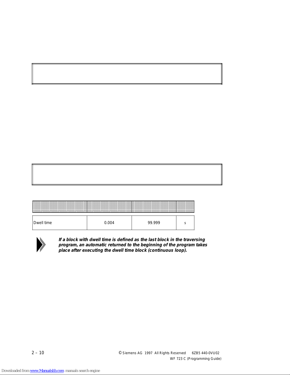
2.3.9 Dwell time
The dwell time is defined by the address character X and the dwell time value.
Programming:
N10 G04 X1.000 M1=10 M2=11 M3=13
A traversing block with dwell time may only contain the G function 04, time and M-functions.
aaaaaaaaaaaaaaaaaaaaaaaaaaaaaaaaaaaaaaaaaaaaaaaaaaaaaaaaaaaaaaaaaaaaaaaaaaaaaaaaaaaaaaaaaaaaa
aaaaaaaaaaaaaaaaaaaaaaaaaaaaaaaaaaaaaaaaaaaaaaaaaaaaaaaaaaaaaaaaaaaaaaaaaaaaaaaaaaaaaaaaaaaaa
aaaaaaaaaaaaaaaaaaaaaaaaaaaaaaaaaaaaaaaaaaaaaaaaaaaaaaaaaaaaaaaaaaaaaaaaaaaaaaaaaaaaaaaaaaaaa
aaaaaaaaaaaaaaaaaaaaaaaaaaaaaaaaaaaaaaaaaaaaaaaaaaaaaaaaaaaaaaaaaaaaaaaaaaaaaaaaaaaaaaaaaaaaa
Designation
aaaaaaaaaaaaaaaaaaaaaaaaaaaaaaaaaaaaaaaaaaaaaaaaaaaaaaaaaaaaaaaaaaaaaaaaaaaaaaaaaaaaaaaaaaaaa
aaaaaaaaaaaaaaaaaaaaaaaaaaaaaaaaaaaaaaaaaaaaaaaaaaaaaaaaaaaaaaaaaaaaaaaaaaaaaaaaaaaaaaaaaaaaa
Dwell time 0.004 99.999
Lower limit Upper limit
Unit
s
If a block with dwell time is defined as the last block in the traversing
program, an automatic returned to the beginning of the program takes
place after executing the dwell time block (continuous loop).
2 – 10 ©
Siemens AG 1997 All Rights Reserved 6ZB5 440-0VU02
WF 723 C (Programming Guide)
Page 20
04.97 Program Execution / Subroutines
3 Program Execution /
Subroutines
3.1 Program execution
Programming:
N10 G90 G01 X100.000 Y200.000 F4000.00 M1=10 M2=11 M3=13
N20 G90 X300.000 F3000.00
N30 G90 Y400.000 F2000.00
N40 M1=30
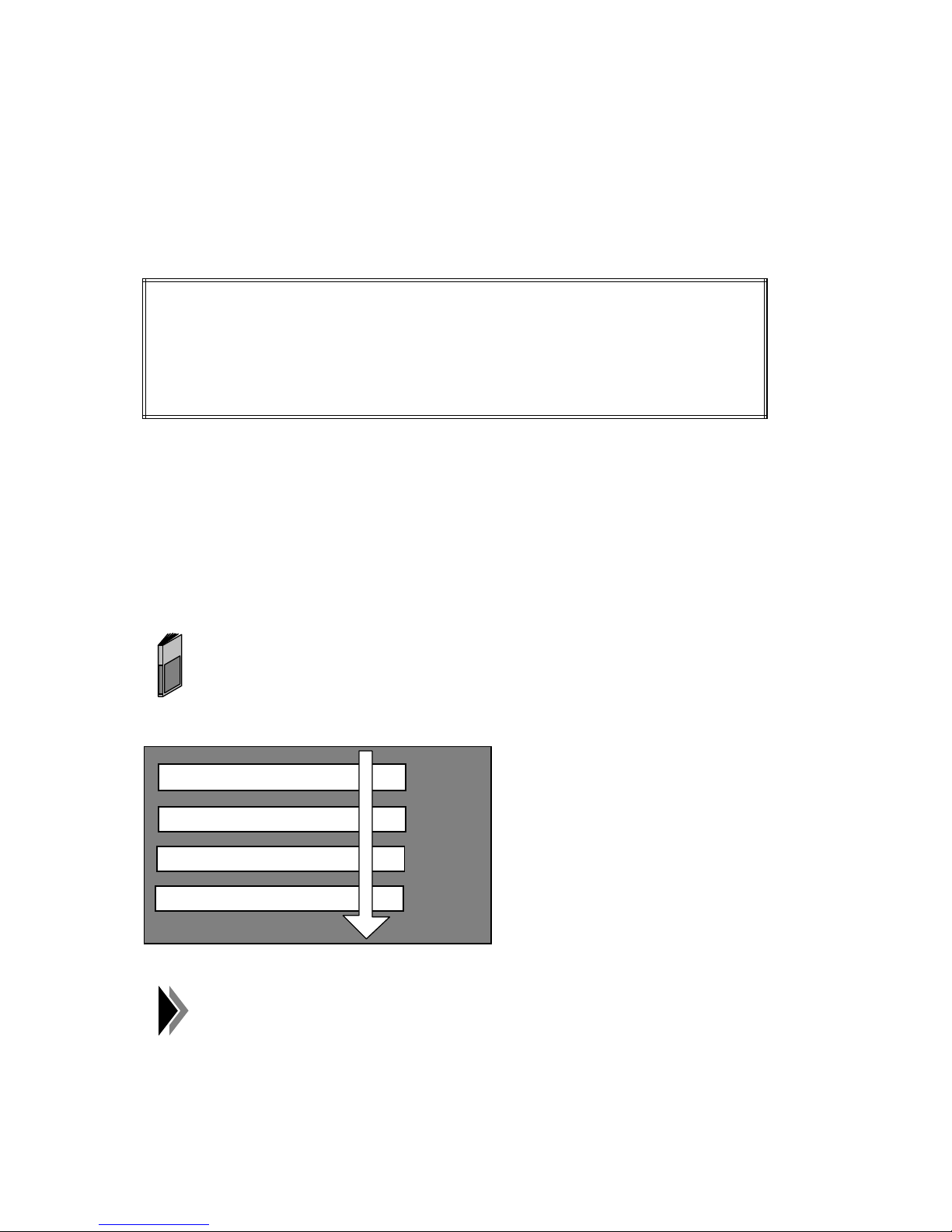
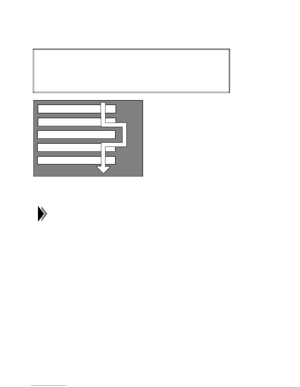
A traversing program is defined by a number of traversing blocks, the block numbers in
ascending order determining the direction of processing.
The WF 723 C is provided with a traversing block decoder which edits the traversing blocks in
such a way that necessary calculations and verifications during execution of the traversing
block can be avoided. This ensures short block-change and executing times.
Apart from basic conditions that have to be met for starting a stored program, the program
number, the read-in enable and the start signal must be available. The read-in enable activates
the traversing block decoder, the start signal enables the traversing block execution.
For a detailed description, see the chapter "control and acknowledgment
signals" in the description of functions.
N10
N20
N30
N40
For roll feed, there is no pre-decoding of traversing block, as they have to
be started one by one externally.
©
Siemens AG 1997 All Rights Reserved 6ZB5 440-0VU02
WF 723 C (Programming Guide)
3 – 1
Page 21
Program Execution / Subroutines 04.97
3.2 Skippable blocks
Programming:
N20 G90 X1.000 F4000.00 M1=10 M2=11 M3=13
/ N30 G90 X2.000 F4000.00
N40 G90 X3.000 F4000.00
N50 M1=30
N10
N20
/ N30
N40
N50
Program blocks that shall not be executed with every program run can be marked as skippable
blocks by the character ”/”. The control signal Skip Block [SA] determines whether skippable
blocks are skipped.
The last traversing block of a program or subroutine must not be skipped.
3 – 2 ©
Siemens AG 1997 All Rights Reserved 6ZB5 440-0VU02
WF 723 C (Programming Guide)
Page 22
04.97 Program Execution / Subroutines
N50 ....
N30 L21 P ..
N20 L20 P ..
N1 ....
N50 ....
N30 L30 P ..
N10 ....
N40 ....
N10 ....
N30 ....
N20 L30 P ..
N10 ....
aaaaaaaaaaaaaaaaaaaaaaaaaaaaaaa
a
a
a
a
a
a
a
a
a
a
Level 0
Main program PR 10
aaaaaaaaaaaaaaaaaaaaaaaaaaa
a
a
a
a
a
a
a
a
a
a
a
Level 1
Subroutine PR 20/PR 21
aaaaaaaaaaaaaaaaaaaaaaaaaaaaaaa
a
a
a
a
a
a
a
a
a
a
Level 2
Subrotuine PR 30
3.3 Subroutines
The WF 723 C offers the subroutine technology for self-contained processes called or
executed several times.
3.3.1 Subroutine call
The subroutine call is defined by the address character L followed by a figure from 1 to 200.
The number of loops is defined by the address character P and a loop value from 0 to 65535.
Programming:
N10 L24 P23
Subroutine call with
Number of loops=23
program number 24
A traversing block with subroutine call must not contain other words apart from the number of
loops.
If 0 is entered as the number of loops, the subroutine will not be called.
3.3.2 Subroutine execution
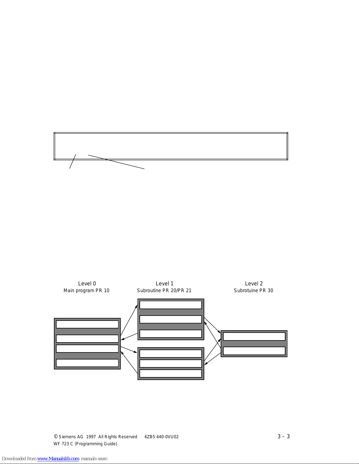
The WF 723 C allows a two-level nesting depth, the number of subroutine calls being only
restricted by the memory space of the WF module.
aaaaaaaaaaaaaaaaaaaaaaaaaaaaa
aaaaaaaaaaaaaaaaaaaaaaaaaaaaa
aaaaaaaaaaaaaaaaaaaaaaaaaaaaa
aaaaaaaaaaaaaaaaaaaaaaaaaaaaa
aaaaaaaaaaaaaaaaaaaaaaaaaaaaa
aaaaaaaaaaaaaaaaaaaaaaaaa
aaaaaaaaaaaaaaaaaaaaaaaaa
aaaaaaaaaaaaaaaaaaaaaaaaa
aaaaaaaaaaaaaaaaaaaaaaaaa
aaaaaaaaaaaaaaaaaaaaaaaaa
a
a
a
a
a
aaaaaaaaaaaaaaaaaaaaaaaaaaaaa
aaaaaaaaaaaaaaaaaaaaaaaaaaaaa
aaaaaaaaaaaaaaaaaaaaaaaaaaaaa
aaaaaaaaaaaaaaaaaaaaaaaaaaaaa
aaaaaaaaaaaaaaaaaaaaaaaaaaaaa
©
Siemens AG 1997 All Rights Reserved 6ZB5 440-0VU02
WF 723 C (Programming Guide)
3 – 3
Page 23

Program Execution / Subroutines 04.97
The WF 723 C does not distinguish between main program or subroutine, i.e. a subroutine can
be directly started like a main program or by a subroutine call.
A called subroutine is executed block by block, starting with the first block number, until a
return to the next higher level is effected. Such a return is triggered by a traversing block with
subroutine end (M17 or M29) or by the execution of the last traversing block of a subroutine.
Modally effective G-functions are effective starting at the block number in which they are
programmed. They stay also effective when jumping to subroutines or back to the main
program.
If a subroutine is terminated with M18, M18 will only be output as an
M-function
➯
no return function.
3.3.3 Programming guidelines
Please adhere to the following guidelines for subroutine execution:
• The 2-level nesting depth must not be exceeded, otherwise the program execution is
aborted and an error message is output.
• Calling a superior program (main program or subroutine) in the subroutine results in an
exceeded nesting depth and is illegal. It is also illegal that a program calls itself.
• When changing program levels, flying block change is not possible. Before the program
level is changed, the axes are brought to an exact stop.
• If subroutine calls are programmed in skippable blocks, the subroutine will not be executed
if the control signal ”Skip block” [SA] is set.
• All definitions in the main program (G- functions, tool offset, zero point offsets, etc.) are
transferred to the subroutines.
3 – 4 ©
Siemens AG 1997 All Rights Reserved 6ZB5 440-0VU02
WF 723 C (Programming Guide)
Page 24
04.97 Program Execution / Subroutines
3.4 Block search forwards
With the "Block search forwards" function, you can start program execution at any point. This
is necessary, for example, if after an abortion of the program execution, you do not want to
start it from the beginning again.
The program will be aborted if during execution
• there is a WF "traversing" error message
(no error that has to be acknowledged with RESET)
• the operating mode is changed
Stopping the program execution by removing the control signal [ST] is not
a program abortion, i.e. by setting [ST], program execution is continued.
The "block search forwards" function distinguishes between "manual block search" and
"automatic block search". Block search forwards is activated by the commands "read in
manual block search" and "read in automatic block search".
The commands are described in the description of functions in chapter
"Command identification" (AK05).
3.4.1 Automatic block search
Upon a program abortion, the WF 723 C automatically saves the data of the interruption point.
After activation of automatic block search, program execution continues at the last point of
interruption, i.e. with the traversing block at which the program was interrupted.
An automatic block search can only be carried out after a program interruption has occurred.
After a RESET of the axis/axes [RST], no automatic block search is
possible.
©
Siemens AG 1997 All Rights Reserved 6ZB5 440-0VU02
WF 723 C (Programming Guide)
3 – 5
Page 25
Program Execution / Subroutines 04.97
aaaaaaaaaaaaaaaaaaaaaaaaaaaaaaa
a
a
a
a
a
a
a
a
a
a
a
a
a
a
a
a
aaaaaaaaaaaaa
a
a
aaa
aaa
aaa
aaa
aaa
a
a
a
a
a
a
a
aaaaaaaaaaaaaaaaaaaaaaaaaaaaaaa
a
a
a
a
a
a
a
a
a
a
a
a
a
a
a
a
aaaaaaaaaaa
a
a
a
a
a
aaa
a
a
a
a
a
a
a
aaa
a
aaa
a
aaa
a
aaa
a
aaaaaaaaaaaaaaaaaaaaaaaaaaaaaaa
a
a
a
a
a
a
a
a
a
a
a
a
a
a
a
a
aaa
a
aaa
a
aaa
a
aaa
a
aaa
a
aaa
a
aaa
a
aaa
a
aaa
a
aaa
a
aaa
a
aaa
a
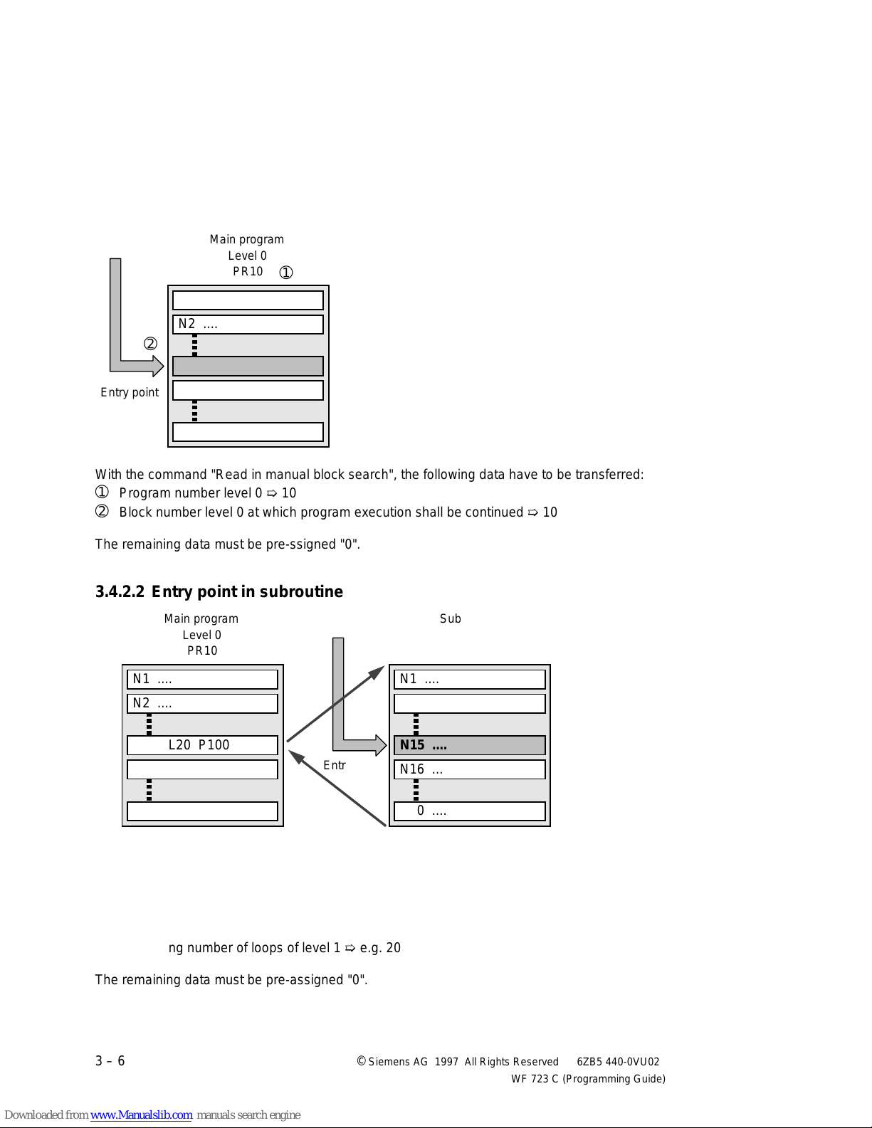
3.4.2 Manual block search
For manual block search, the exact data of the entry point in the traversing program must be
defined to the WF 723 C.
3.4.2.1 Entry point in the main program
aaaaaaaaaaaaaaaaaaaaaaaaaaaaa
Main program
aaaaaaaaaaaaaaaaaaaaaaaaaaaaa
aaaaaaaaaaaaaaaaaaaaaaaaaaaaa
aaaaaaaaaaaaaaaaaaaaaaaaaaaaa
aaaaaaaaaaaaaaaaaaaaaaaaaaaaa
aaaaaaaaaaaaaaaaaaaaaaaaaaaaa
aaaaaaaaaaaaaaaaaaaaaaaaaaaaa
aaaaaaaaaaaaaaaaaaaaaaaaaaaaa
Level 0
PR10
➀
a
a
a
a
a
a
N1 ....
N2 ....
➁
N10 ....
aaaaaaaaaaa
Entry point
aaaaaaaaaaa
N11 ....
N20 ....
With the command "Read in manual block search", the following data have to be transferred:
➀
Program number level 0 ➯ 10
➁
Block number level 0 at which program execution shall be continued ➯ 10
The remaining data must be pre-ssigned "0".
3.4.2.2 Entry point in subroutine level 1
aaaaaaaaaaaaaaaaaaaaaaaaaaaaa
Main program
aaaaaaaaaaaaaaaaaaaaaaaaaaaaa
aaaaaaaaaaaaaaaaaaaaaaaaaaaaa
aaaaaaaaaaaaaaaaaaaaaaaaaaaaa
aaaaaaaaaaaaaaaaaaaaaaaaaaaaa
aaaaaaaaaaaaaaaaaaaaaaaaaaaaa
aaaaaaaaaaaaaaaaaaaaaaaaaaaaa
aaaaaaaaaaaaaaaaaaaaaaaaaaaaa
Level 0
PR10
N1 ....
N2 ....
N10 L20 P100
➁
N11 ....
➀
➄
Entry point
aaaaaaaaa
aaaaaaaaa
aaaaaaaaaaaaaaaaaaaaaaaaaaaaa
Subroutine
aaaaaaaaaaaaaaaaaaaaaaaaaaaaa
aaaaaaaaaaaaaaaaaaaaaaaaaaaaa
aaaaaaaaaaaaaaaaaaaaaaaaaaaaa
aaaaaaaaaaaaaaaaaaaaaaaaaaaaa
aaaaaaaaaaaaaaaaaaaaaaaaaaaaa
aaaaaaaaaaaaaaaaaaaaaaaaaaaaa
aaaaaaaaaaaaaaaaaaaaaaaaaaaaa
Level 1
PR20
N1 ....
N2 ....
a
a
a
a
➃
a
a
N15 ....
a
a
N16 ....
➂
N20 ....
With the command "Read in manual block search", the following data have to be transferred:
①
Program number level 0 ➯ 10
➁
Block number level 0 at which the subroutine is called ➯ 10
➂
Program number level 1 ➯ 20
➃
Block number level 1 at which program execution shall be continued ➯ 15
➄
Remaining number of loops of level 1 ➯ e.g. 20
The remaining data must be pre-assigned "0".
3 – 6 ©
N20 ....
Siemens AG 1997 All Rights Reserved 6ZB5 440-0VU02
WF 723 C (Programming Guide)
Page 26
04.97 Program Execution / Subroutines
aaaaaaaaaaaaaaaaaaaaaaa
a
a
a
a
a
a
a
a
a
a
a
a
a
a
a
a
a
aaa
a
a
a
a
a
a
a
aaa
a
a
a
a
a
aaa
a
a
a
a
a
a
a
aaa
a
a
a
a
a
a
a
aaaaaaaaaaaaaaaaaaaaaaa
a
a
a
a
a
a
a
a
a
a
a
a
a
a
a
a
aaa
a
a
a
a
a
a
a
aaaaaaaaaaaaa
a
a
a
a
aaa
a
a
a
a
a
a
a
aaa
a
a
a
a
a
a
a
aaaaaaaaaaaaaaaaaaaaaaa
a
a
a
a
a
a
a
a
a
a
a
a
a
a
a
a
a
aaa
a
a
a
a
a
a
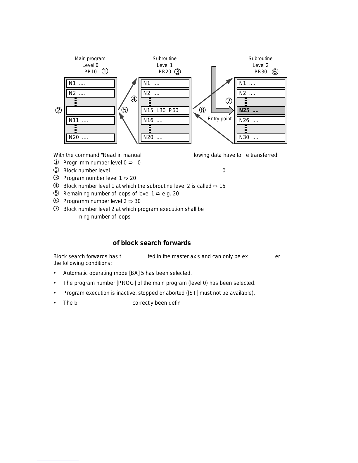
a
3.4.2.3 Entry point in subroutine level 2
aaaaaaaaaaaaaaaaaaaaa
Main program
aaaaaaaaaaaaaaaaaaaaa
aaaaaaaaaaaaaaaaaaaaa
aaaaaaaaaaaaaaaaaaaaa
Level 0
aaaaaaaaaaaaaaaaaaaaa
aaaaaaaaaaaaaaaaaaaaa
aaaaaaaaaaaaaaaaaaaaa
PR10
aaaaaaaaaaaaaaaaaaaaa
N1 ....
➀
a
a
a
a
a
a
a
a
a
a
a
a
a
a
aaaaaaaaaaaaaaaaaaaaa
Subroutine
aaaaaaaaaaaaaaaaaaaaa
aaaaaaaaaaaaaaaaaaaaa
aaaaaaaaaaaaaaaaaaaaa
Level 1
aaaaaaaaaaaaaaaaaaaaa
aaaaaaaaaaaaaaaaaaaaa
aaaaaaaaaaaaaaaaaaaaa
PR20
aaaaaaaaaaaaaaaaaaaaa
➂
a
a
a
a
a
a
N1 ....
aaaaaaaaaaaaaaaaaaaaa
Subroutine
aaaaaaaaaaaaaaaaaaaaa
aaaaaaaaaaaaaaaaaaaaa
aaaaaaaaaaaaaaaaaaaaa
Level 2
aaaaaaaaaaaaaaaaaaaaa
aaaaaaaaaaaaaaaaaaaaa
aaaaaaaaaaaaaaaaaaaaa
PR30
aaaaaaaaaaaaaaaaaaaaa
➅
a
a
a
a
a
a
N1 ....
a
a
a
a
a
a
a
a
N2 ....
a
a
a
a
N10 L10 P100
➁
a
a
N11 ....
N20 ....
➄
a
a
a
a
a
a
a
➃
a
a
a
a
a
N2 ....
N15 L30 P60
N16 ....
N20 ....
a
a
a
a
➇
a
a
Entry point
➆
aaaaaaaaaaa
aaaaaaaaaaa
a
a
a
a
a
a
N2 ....
N25 ....
N26 ....
N30 ....
With the command "Read in manual block search", the following data have to be transferred:
①
Programm number level 0 ➯ 10
➁
Block number level 0 at which the subroutine level 1 is called ➯ 10
➂
Program number level 1 ➯ 20
➃
Block number level 1 at which the subroutine level 2 is called ➯ 15
➄
Remaining number of loops of level 1 ➯ e.g. 20
➅
Programm number level 2 ➯ 30
➆
Block number level 2 at which program execution shall be continued ➯ 25
➇
Remaining number of loops of level 2 ➯ e.g. 5
3.4.3 Conditions of block search forwards
Block search forwards has to be activated in the master axis and can only be executed under
the following conditions:
• Automatic operating mode [BA] 5 has been selected.
• The program number [PROG] of the main program (level 0) has been selected.
• Program execution is inactive, stopped or aborted ([ST] must not be available).
• The block search data have correctly been defined.
Any faulty operation generates a corresponding Data exchange/traversing WF error message.
After successful activation through the command "read in automatic/manual block search", the
current block search data can be checked with the command "read out block search", as long
as program execution has not yet been started. Afterwards, the output block search data will
be "0".
©
Siemens AG 1997 All Rights Reserved 6ZB5 440-0VU02
WF 723 C (Programming Guide)
3 – 7
Page 27

Program Execution / Subroutines 04.97
3.4.4 Program start after activation of block search forwards
Program decoding is effected from the beginning of the program. Axis movements and the
output of M-functions are only effected from the defined entry point. Tool offsets, zero point
offsets, self-holding G-functions and velocities are maintained up to the entry point.
Important hints:
• If a jump is made to a block with incremental dimension (G91), the entire traversing path
will be traversed, even if before the program abortion part of the path was already
traversed.
• M-functions of the block jumped to will be output, even if they were already output before
the program abortion.
• If a program execution is interrupted and the M-functions are still pending, they will be
deleted through the block search forwards.
3 – 8 ©
Siemens AG 1997 All Rights Reserved 6ZB5 440-0VU02
WF 723 C (Programming Guide)
Page 28
04.97 Programming of Traversing Blocks
a
a
a
a
a
a
a
a
a
a
a
a
aaa
aaa
aaa
aaa
aaa
aaa
aaa
a
a
a
a
a
a
aaa
aaa
aaa
aaaaaaaaa
aaaaaaaaa
aaaaaaaaa
aaaaaaaaaaaaaaaaaaaaaaaaaaaaaaaaaaaaaaaaaaa
a
a
a
a
a
a
a
a
a
a
a
a
a
a
a
a
a
a
a
a
a
a
a
a
a
a
a
a
a
a
a
a
a
a
a
a
a
a
a
a
a
a
a
a
a
a
a
a
a
a
a
a
a
a
a
4 Programming of Traversing Blocks
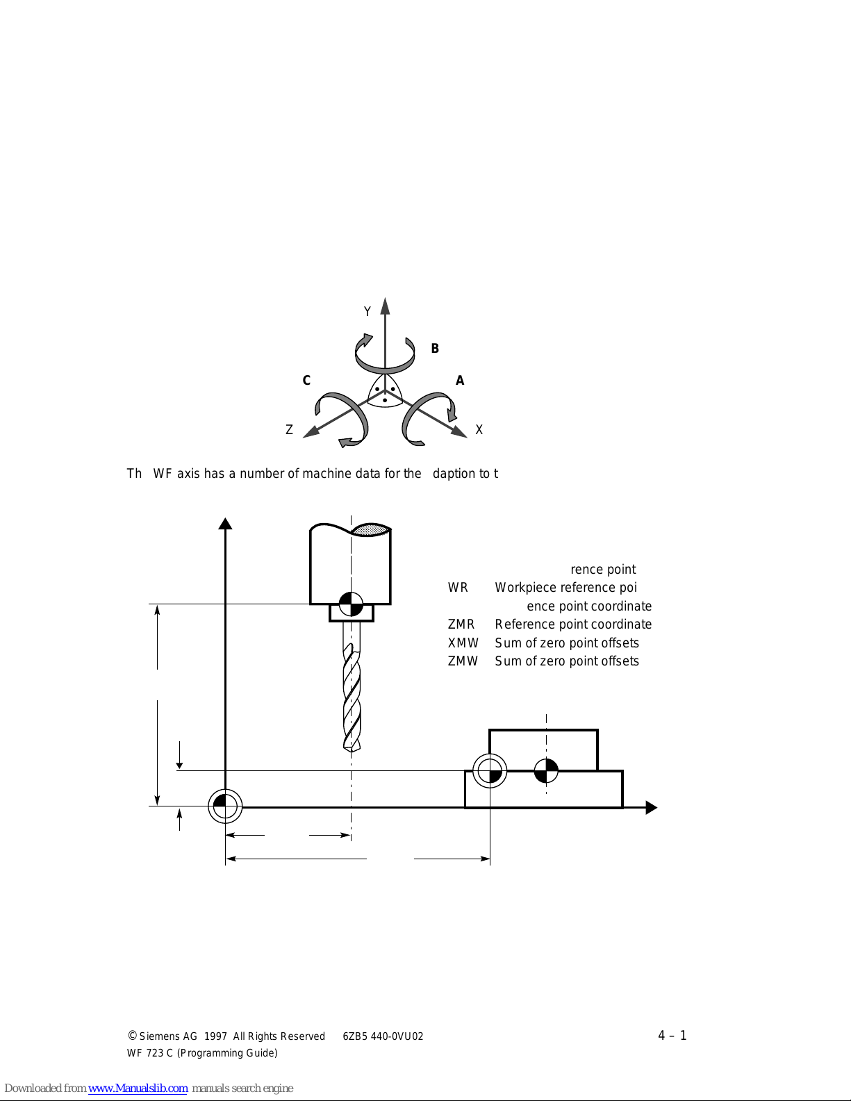
4.1 Coordinate system and reference point
The traversing directions of a machine tool refer to a coordinate system assigned to the
traversing axes of the machine tool. A right-handed and right-angled coordinate system with
the axes X, Y, and Z is used. The coordinate system is assigned to the main axes of the
machine tool.
Y
B
C
Z
A
X
The WF axis has a number of machine data for the adaption to the coordinate system that
have to be entered during installation.
aaaaaaaaaaaaaaaaaaaaaaaaaaaaaaaaaaaaaaaaa
M Machine zero point
+Z
R
aaaaaaaaaaaaaaaaaaaaaaaaaaaaaaaaaaaaaaaaa
aaaaaaaaaaaaaaaaaaaaaaaaaaaaaaaaaaaaaaaaa
aaaaaaaaaaaaaaaaaaaaaaaaaaaaaaaaaaaaaaaaa
aaaaaaaaaaaaaaaaaaaaaaaaaaaaaaaaaaaaaaaaa
W Workpiece zero point
aaaaaaaaaaaaaaaaaaaaaaaaaaaaaaaaaaaaaaaaa
aaaaaaaaaaaaaaaaaaaaaaaaaaaaaaaaaaaaaaaaa
aaaaaaaaaaaaaaaaaaaaaaaaaaaaaaaaaaaaaaaaa
R Machine reference point
aaaaaaaaaaaaaaaaaaaaaaaaaaaaaaaaaaaaaaaaa
aaaaaaaaaaaaaaaaaaaaaaaaaaaaaaaaaaaaaaaaa
aaaaaaaaaaaaaaaaaaaaaaaaaaaaaaaaaaaaaaaaa
aaaaaaaaaaaaaaaaaaaaaaaaaaaaaaaaaaaaaaaaa
WR Workpiece reference point
aaaaaaaaaaaaaaaaaaaaaaaaaaaaaaaaaaaaaaaaa
aaaaaaaaaaaaaaaaaaaaaaaaaaaaaaaaaaaaaaaaa
aaaaaaaaaaaaaaaaaaaaaaaaaaaaaaaaaaaaaaaaa
aaaaaaaaaaaaaaaaaaaaaaaaaaaaaaaaaaaaaaaaa
XMR Reference point coordinate
aaaaaaaaaaaaaaaaaaaaaaaaaaaaaaaaaaaaaaaaa
aaaaaaaaaaaaaaaaaaaaaaaaaaaaaaaaaaaaaaaaa
aaaaaaaaaaaaaaaaaaaaaaaaaaaaaaaaaaaaaaaaa
ZMR Reference point coordinate
aaaaaaaaaaaaaaaaaaaaaaaaaaaaaaaaaaaaaaaaa
aaaaaaaaaaaaaaaaaaaaaaaaaaaaaaaaaaaaaaaaa
aaaaaaaaaaaaaaaaaaaaaaaaaaaaaaaaaaaaaaaaa
aaaaaaaaaaaaaaaaaaaaaaaaaaaaaaaaaaaaaaaaa
XMW Sum of zero point offsets
aaaaaaaaaaaaaaaaaaaaaaaaaaaaaaaaaaaaaaaaa
aaaaaaaaaaaaaaaaaaaaaaaaaaaaaaaaaaaaaaaaa
aaaaaaaaaaaaaaaaaaaaaaaaaaaaaaaaaaaaaaaaa
aaaaaaaaaaaaaaaaaaaaaaaaaaaaaaaaaaaaaaaaa
ZMW Sum of zero point offsets
ZMR
W
a
a
a
a
a
a
a
a
a
a
a
a
a
a
a
a
a
a
a
a
a
a
a
a
a
a
a
ZMW
M
XMR
©
Siemens AG 1997 All Rights Reserved 6ZB5 440-0VU02
WF 723 C (Programming Guide)
WR
+X
XMW
4 – 1
Page 29
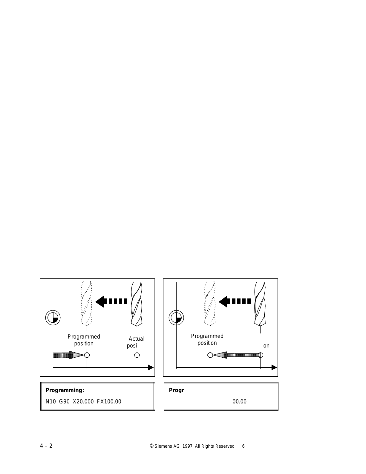
Programming of Traversing Blocks 04.97
aaaaaaa
a
a
a
a
aaaaaaaaaaaaaaa
a
aaaaaaa
a
aaaaaaa
a
aaaaaaa
a
aaa
a
a
a
a
a
aaaaaaa
a
aaaaaaa
a
aaaaaaa
a
aaaaaaa
a
Usually, the definitions according to the DIN standard 66025 apply. If the axis is traversed
towards the workpiece, the actual value must decrease, i.e the traversing direction is negative.
When traversing from the workpiece the actual value increases and the axes executes a
positive movement. The reference point definitions are different for every machine tool, but, in
most cases, the reference point is the zero point of the workpiece. The programming of the
traversing blocks of the WF axis also refers to the zero point. Furthermore, the following
coordinate-specific machine data refer to the zero point:
• Reference point coordinate (MD 3)
• Reference point traversing direction (MD 5)
• Limit switch (MD 20, MD 21)
4.2 Dimensions G90, G91
The traversing direction to a specified point can be defined by the
• absolute dimension G90 or
• incremental dimension G91
The user can switch between absolute and incremental dimensions as desired. When
switching the machine on, the programming status refers to absolute dimensioning G90. G90
and G91 are modal. Thus, G90 or G91 only have to be entered when switching over to the
other dimension.
4.2.1 Linear axis
Absolute dimension G90 Incremental dimension G91
Absolute dimensions refer, in most cases, Incremental dimensions refer to the
to the workpiece zero point W or last actual position.
machine zero point M.
W
Programmed
position
aaaaa
a
a
aaaaa
a
a
0 1020304050mm
Actual
position
Programming:
N10 G90 X20.000 FX100.00
W
Programmed
position
0 1020304050mm
Programming:
N10 G91 X-30.000 FX100.00
Actual
position
4 – 2 ©
Siemens AG 1997 All Rights Reserved 6ZB5 440-0VU02
WF 723 C (Programming Guide)
Page 30
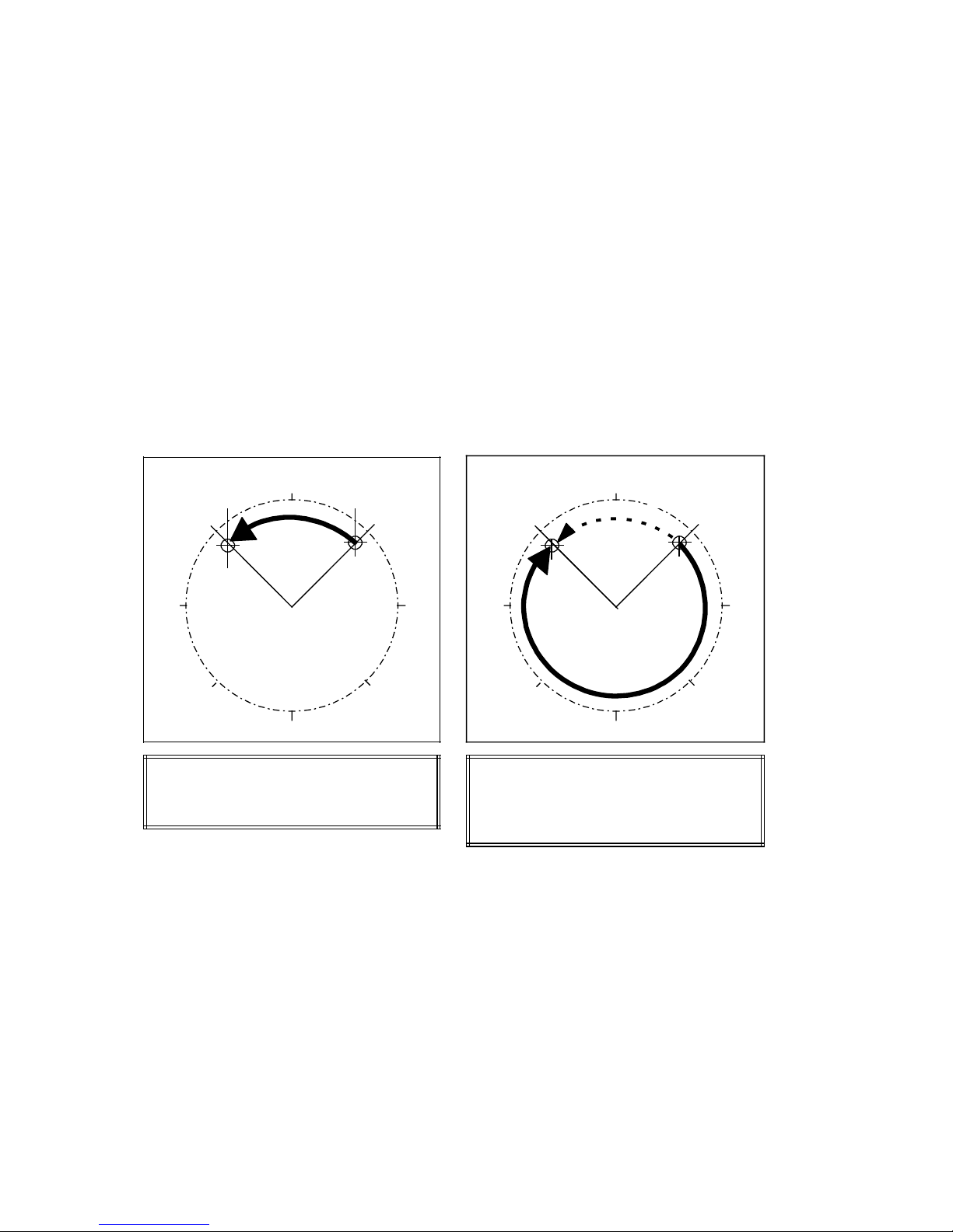
04.97 Programming of Traversing Blocks
4.2.2 Rotary axis, shortest distance G68
If the WF axis is used as a rotary axis, the measuring system should be ajusted in such a way
that the dimensions refer to a full circle (e.g. 1°/1000), so that the positions that can be
reached lie between 0° and 360°. Any other adjustment is also possible.
• Absolute dimension G90
When using a full circle with 360°, the input of absolute dimensions (G90) has the
particularity that there are always 2 possibilities to reach the set position.
G68 - shortest distance
When G68 is programmed, the axis moves
to the programmed position, traversing the
shortest possible distance and ignoring the
sign of the position value. G68 is effective
block by block.
Programmed
position
o
315
o
270
o
225
0
180
Actual
o
position
o
45
o
135
o
90
Programming the direction of rotation
The axis traverses to the programmed
position, the sign of the position value
defining the traversing direction:
+: Traversing in the direction of increasing
degrees (actual values)
– : Traversing in the direction of decreasing
degrees (set values)
Programmed
position
o
315
o
270
o
o
225
0
180
o
o
Actual
position
135
45
o
o
90
o
Programming:
N10 G90 G68 C315.000 FC1000.00
• Incremental dimension G91
When the incremental dimension G91 is programmed, the direction of rotation of the rotary
axis is determined by the sign of the position set value. Several revolutions may be
programmed if a multiple of 360° is defined as the position set value.
If G68 is programmed in connection with G91, an error message will be output.
©
Siemens AG 1997 All Rights Reserved 6ZB5 440-0VU02
WF 723 C (Programming Guide)
Programming:
N10 G90 C315.000 FC1000.00
(or N10 G90 C-315.000 FC1000.00)
4 – 3
Page 31
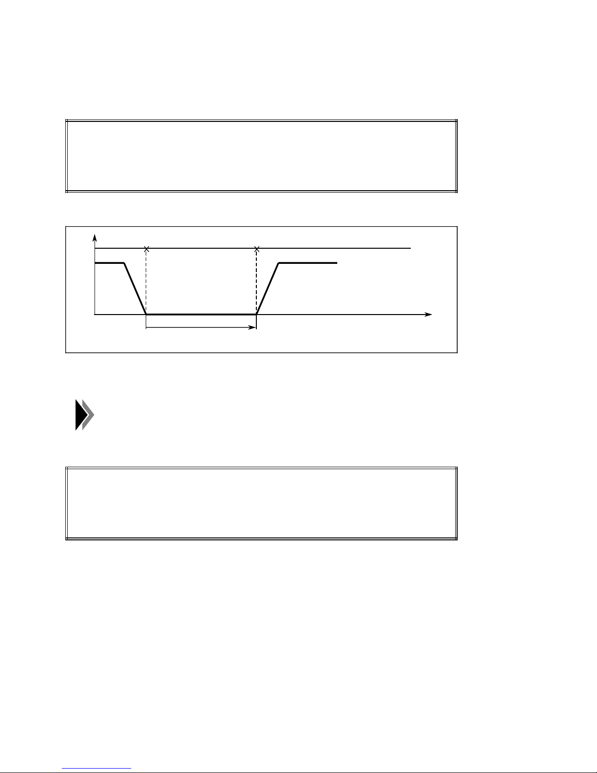
Programming of Traversing Blocks 04.97
4.3 Dwell time G04
Dwell times are required to stop the machine control for a defined period.
Programming:
N10 G90 G01 X50.000 F4000.00
N20 G04 X3.000
N30 G91 X2.000
Program sequence:
V
N20N10
Dwell time = 3s
N30
Dwell times are only effective block by block and must be reselected is necessary.
A dwell time in the last block results in a jump to the beginning of the
program (continuous loop).
Programming:
N10 G90 G01 X10.000 F400.00
N20 X-2.000
N30 G04 X0.100
t
The program end is here characterized by G04 and a time value. After the dwell time of
100 ms has expired, there is an automatic return to the beginning of the program and the
sequence is repeated.
4 – 4 ©
Siemens AG 1997 All Rights Reserved 6ZB5 440-0VU02
WF 723 C (Programming Guide)
Page 32
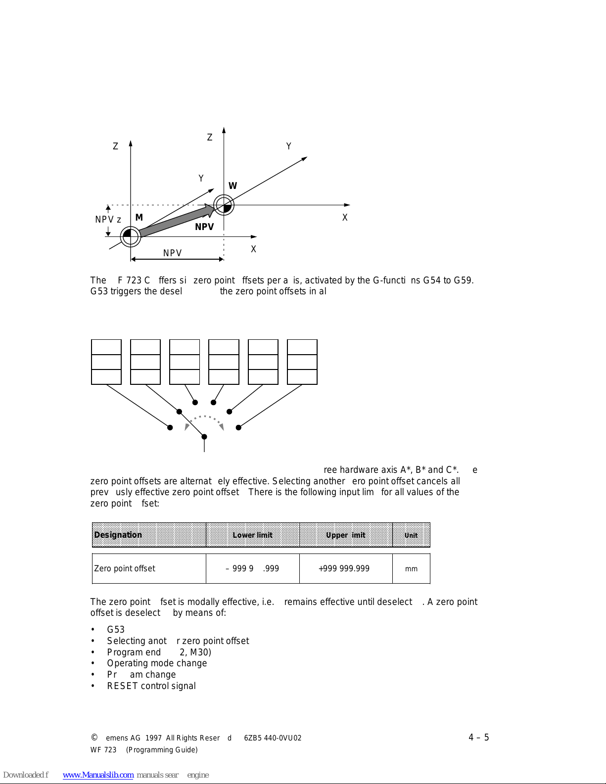
04.97 Programming of Traversing Blocks
aaa
aaa
aaa
aaa
aaa
aaa
a
a
a
a
a
a
a
a
a
a
a
a
aaa
aaa
aaa
aaa
aaa
aaa
aaa
a
a
a
a
a
aaa
aaa
aaa
aaaaaaaaa
a
a
a
a
aaaaaaa
a
a
a
a
aaaaaaa
a
a
a
a
a
aaaaaaa
a
a
a
a
a
aaaaaaa
a
a
a
a
a
aaaaaaa
a
a
a
a
a
aaaaaaa
a
a
a
a
a
aaaaaaa
a
a
a
a
a
aaaaaaa
a
a
a
a
a
aaaaaaa
a
a
a
a
a
aaaaaaa
a
a
a
a
a
aaaaaaa
a
a
a
a
a
aaaaaaa
a
a
a
a
a
aaaaaaa
a
a
a
a
a
aaaaaaa
a
a
a
a
a
aaaaaaa
a
a
a
a
a
aaaaaaa
a
a
a
a
a
aaaaaaa
a
a
a
a
a
aaaaaaa
a
a
a
a
a
aaaaaaa
a
a
a
a
a
aaaaaaa
a
a
a
a
a
aaaaaaa
a
a
a
a
a
aaaaaaa
a
a
a
a
a
aaaaaaa
a
a
a
a
a
aaaaaaa
a
a
a
a
a
aaaaaaa
a
a
a
a
a
aaaaaaa
a
a
a
a
a
aaaaaaa
a
a
a
a
a
aaaaaaa
a
a
a
a
a
aaaaaaa
a
a
a
a
a
aaaaaaa
a
a
a
a
a
aaaaaaa
a
a
a
a
a
aaaaaaaaaaaaaaaaaaaaaaaaaaaaa
a
a
a
a
a
aaaaaaaaaaaaaaaaaaaaaaaaaaaaaaaaaaaaaaaaaaaaaaaaaaaaaaaaaaaaaaaaaaaaaaaaaaaaaaaaaaaaaaaaaaaaaaa
a
a
a
a
a
a
a
a
a
a
a
a
a
4.4 Zero point offset G53, G54 bis G59
The zero point offset is the distance between the workpiece zero point W and the machine
zero point M.
Z
NPV z
Y
W
a
a
M
a
a
aaaaaaa
NPV x
aaaaaaa
aaaaa
NPV
aaaaa
X
Y
X
The WF 723 C offers six zero point offsets per axis, activated by the G-functions G54 to G59.
G53 triggers the deselection of the zero point offsets in all axes.
aaaaa
a
aaaaa
a
aaaaa
a
aaaaa
a
aaaaa
a
aaaaa
a
Z
1st
aaaaa
aaaaa
G54
aaaaa
aaaaa
aaaaa
A*
aaaaa
B*
aaaaa
aaaaa
C*
aaaaa
2nd
a
aaaaa
a
aaaaa
G55
a
aaaaa
a
aaaaa
a
aaaaa
A*
a
aaaaa
B*
a
aaaaa
a
aaaaa
C*
a
aaaaa
3rd
a
aaaaa
a
aaaaa
G56
a
aaaaa
a
aaaaa
a
aaaaa
A*
a
aaaaa
B*
a
aaaaa
a
aaaaa
C*
a
aaaaa
4th
a
aaaaa
a
aaaaa
G57
a
aaaaa
a
aaaaa
a
aaaaa
A*
a
aaaaa
B*
a
aaaaa
a
aaaaa
C*
a
aaaaa
5th
a
aaaaa
a
aaaaa
G58
a
aaaaa
a
aaaaa
a
aaaaa
A*
a
aaaaa
B*
a
aaaaa
a
aaaaa
C*
a
aaaaa
6th
a
aaaaa
a
aaaaa
G59
a
aaaaa
a
aaaaa
a
aaaaa
A*
a
aaaaa
B*
a
aaaaa
a
aaaaa
C*
a
aaaaa
aaaaaaaaaaaaaaaaaaaaaaaaaaa
Settable zero point offset
a
aaaaaaaaaaaaaaaaaaaaaaaaaaa
a
a
a
a
a
a
a
a
a
a
Each zero point offset includes the values defining the three hardware axis A*, B* and C*. The
zero point offsets are alternatively effective. Selecting another zero point offset cancels all
previously effective zero point offsets. There is the following input limit for all values of the
zero point offset:
aaaaaaaaaaaaaaaaaaaaaaaaaaaaaaaaaaaaaaaaaaaaaaaaaaaaaaaaaaaaaaaaaaaaaaaaaaaaaaaaaaaaaaaaaaaaa
aaaaaaaaaaaaaaaaaaaaaaaaaaaaaaaaaaaaaaaaaaaaaaaaaaaaaaaaaaaaaaaaaaaaaaaaaaaaaaaaaaaaaaaaaaaaa
aaaaaaaaaaaaaaaaaaaaaaaaaaaaaaaaaaaaaaaaaaaaaaaaaaaaaaaaaaaaaaaaaaaaaaaaaaaaaaaaaaaaaaaaaaaaa
Designation
aaaaaaaaaaaaaaaaaaaaaaaaaaaaaaaaaaaaaaaaaaaaaaaaaaaaaaaaaaaaaaaaaaaaaaaaaaaaaaaaaaaaaaaaaaaaa
aaaaaaaaaaaaaaaaaaaaaaaaaaaaaaaaaaaaaaaaaaaaaaaaaaaaaaaaaaaaaaaaaaaaaaaaaaaaaaaaaaaaaaaaaaaaa
aaaaaaaaaaaaaaaaaaaaaaaaaaaaaaaaaaaaaaaaaaaaaaaaaaaaaaaaaaaaaaaaaaaaaaaaaaaaaaaaaaaaaaaaaaaaa
Lower limit Upper limit
Zero point offset – 999 999.999 +999 999.999
The zero point offset is modally effective, i.e. it remains effective until deselected. A zero point
offset is deselected by means of:
• G53
• Selecting another zero point offset
• Program end (M02, M30)
• Operating mode change
• Program change
• RESET control signal
©
Siemens AG 1997 All Rights Reserved 6ZB5 440-0VU02
WF 723 C (Programming Guide)
a
a
a
Unit
a
a
a
mm
4 – 5
Page 33
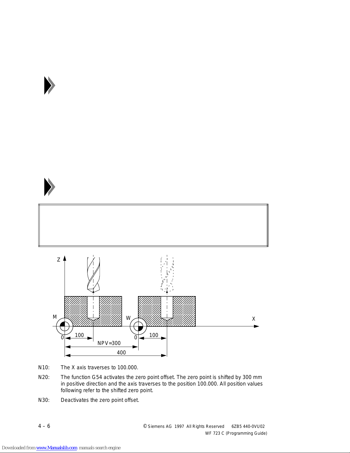
Programming of Traversing Blocks 04.97
aaaaaaaaaaaaaaaaaaaaaaaaaaaaa
aaaaaaaaaaaaaaaaaaaaaaaaaaaaa
aaaaaaaaaaaaaaaaaaaaaaaaaaaaa
aaaaaaaaaaaaaaaaaaaaaaaaaaaaa
aaaaaaaaaaaaaaaaaaaaaaaaaaaaa
aaaaaaaaaaaaaaaaaaaaaaaaaaaaa
aaaaaaaaaaaaaaaaaaaaaaaaaaaaa
aaaaaaaaaaaaaaaaaaaaaaaaaaaaa
aaaaaaaaaaaaaaaaaaaaaaaaaaaaa
aaaaaaaaaaaaaaaaaaaaaaaaaaaaa
aaaaaaaaaaaaaaaaaaaaaaaaaaaaa
aaaaaaaaaaaaaaaaaaaaaaaaaaaaa
aaaaaaaaaaaaaaaaaaaaaaaaaaaaa
aaaaaaaaaaaaaaaaaaaaaaaaaaaaa
aaaaaaaaaaaaaaaaaaaaaaaaaaaaa
aaaaaaaaaaaaaaaaaaaaaaaaaaaaa
aaaaaaaaaaaaaaaaaaaaaaaaaaaaa
aaaaaaaaaaaaaaaaaaaaaaaaaaaaa
aaaaaaaaaaaaaaaaaaaaaaaaaaaaa
aaaaaaaaaaaaaaaaaaaaaaaaaaaaa
aaaaaaaaaaaaaaaaaaaaaaaaaaaaa
aaaaaaaaaaaaaaaaaaaaaaaaaaaaa
aaaaaaaaaaaaaaaaaaaaaaaaaaaaa
aaaaaaaaaaaaaaaaaaaaaaaaaaaaa
aaaaaaaaaaaaaaaaaaaaaaaaaaaaa
aaaaaaaaaaaaaaaaaaaaaaaaaaaaa
aaaaaaaaaaaaaaaaaaaaaaaaaaaaa
aaaaaaaaaaaaaaaaaaaaaaaaaaaaa
aaaaaaaaaaaaaaaaaaaaaaaaaaaaa
aaaaaaaaaaaaaaaaaaaaaaaaaaaaa
aaaaa
a
a
a
a
a
aaaaa
a
a
a
a
aaaaa
a
a
a
a
a
aaa
aaa
aaa
a
a
a
a
a
a
aaa
aaa
aaa
aaa
aaa
aaa
aaa
a
a
a
a
a
aaa
aaa
aaa
aaaaaaaaaaaaa
a
a
a
a
At the beginning of the program no zero point offset is active, i.e. it must be selected if
required. This does not apply to subroutines. A zero point offset selected in the main program
is also effective in the subroutine. A zero point offset selected in the subroutine is also
effective in the main program.
All values for the zero point offsets used in a program must be transferred
before program start.
The path to be traversed in a block is determined under consideration of all offsets and
compensations:
Absolute programming G90:
• Selection of NPV: Path=new set position – old set position+NPV
• New selection of NPV: Path=new set position – old set position+new NPV – old NPV
• Deselection of NPV: Path=new set position – old set position – NPV
NPV=zero point offset
Incremental programming G91:
• Path=incremental dimension
The absolute positions of the software limit switches remain when using
the zero point offset as these refer to the machine zero point.
Programming:
N10 G90 X100.000 FX5000.00
N20 G90 G54 X100.000
N30 G53 .....
Z
a
a
M
a
a
aaa
100
aaa
0
aaaaaaaaaaa
NPV=300
aaaaaaaaaaa
aaa
aaa
400
W
a
a
N10: The X axis traverses to 100.000.
X
aaa
a
100
aaa
0
a
N20: The function G54 activates the zero point offset. The zero point is shifted by 300 mm
in positive direction and the axis traverses to the position 100.000. All position values
following refer to the shifted zero point.
N30: Deactivates the zero point offset.
4 – 6 ©
Siemens AG 1997 All Rights Reserved 6ZB5 440-0VU02
WF 723 C (Programming Guide)
Page 34
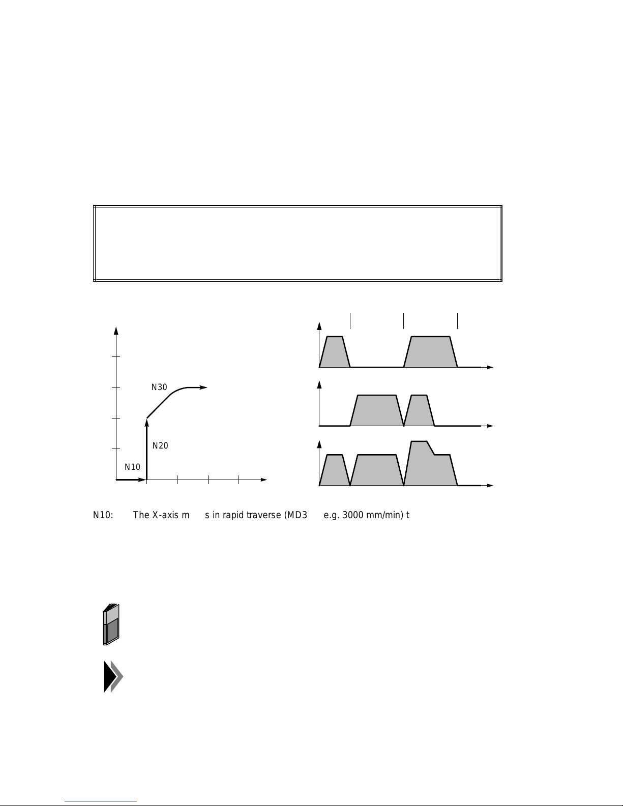
04.97 Programming of Traversing Blocks
aaaaa
a
a
a
a
a
a
aaaaa
a
a
a
a
a
aaaaa
a
a
a
a
4.5 Chaining with rapid traverse G76
The path programmed with G76 "chaining with rapid traverse" is traversed in each axis with
maximum traversing speed (MD31), the resulting path being dependent on the distances to be
traversed and the axis velocities.
The rapid traversing movements are programmed through the preparatory function G76 and
indication of the point of destination. The point of destination can be specified in absolute
dimension G90 or in incremental dimension G91. G76 is modally effective. With "chaining with
rapid traverse", one, two or all three axes can be traversed simultaneously.
Programming:
N10 G76 X10.000
N20 Y20.000
N30 X30.000 Y30.000
Movement in the
coordinate system:
Y
40.
aaa
N30
aaa
v-t diagrams:
V
x
MD 31
V
y
N10 N20 N30
MD 31
10.
N20
aaa
a
aaa
aaa
N10
aaa
10. 40.
V
path
X
aaa
a
N10: The X-axis moves in rapid traverse (MD31 = e.g. 3000 mm/min) to position X10.000.
N20: The Y-axis moves in rapid traverse (MD31 = e.g. 3000 mm/min) to position Y20.000.
N30: The X and Y-axes move in rapid traverse to position X30.000/Y30.000. Each axis
traverses at its own maximum velocity (MD31). As the distance to traverse of the Yaxis is shorter than that of the X-axis, the Y-axis reaches its point of destination
earlier.
t
t
t
In this example, "exact stop G60" is assumed to be the block transition
behaviour. In the chapter "block transitions", the different possibilities of
block transition are described in detail.
As for chaining in rapid traverse, the override is effective, the maximum
traversing velocity is only reached with 100% override.
©
Siemens AG 1997 All Rights Reserved 6ZB5 440-0VU02
WF 723 C (Programming Guide)
4 – 7
Page 35
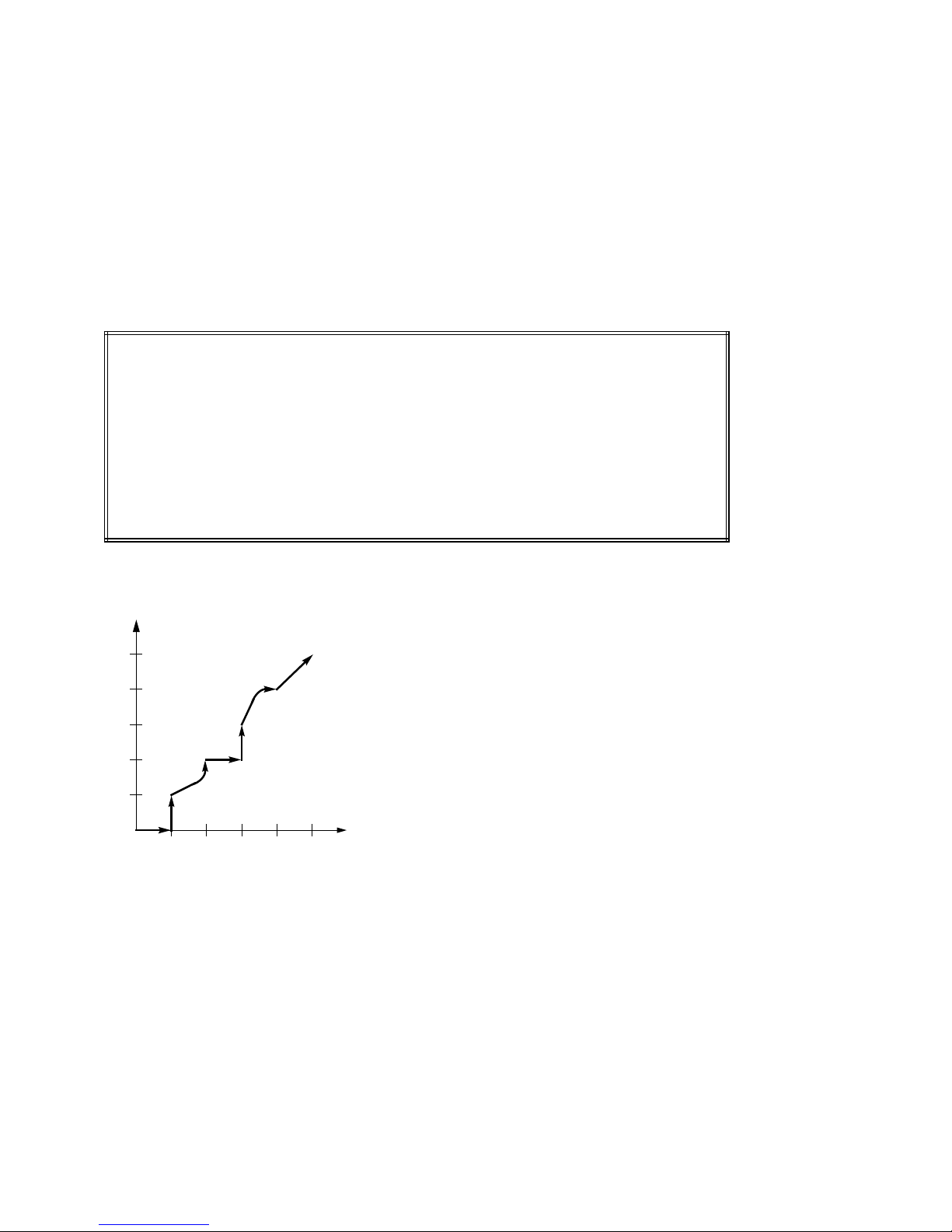
Programming of Traversing Blocks 04.97
4.6 Chaining with axis velocity G77
The path programmed with G77 "chaining with axis velocity" is traversed in each axis with the
programmed traversing speed, the resulting path being dependent on the distances to be
traversed and the axis velocities.
The "chaining with axis velocity" is programmed through the preparatory function G77,
indication of a point of destination, and the axis velocities. The point of destination can be
specified in absolute dimension G90 or in incremental dimension G91. G77 is modally
effective. With "chaining with axis velocity", one, two or all three axes can be traversed
simultaneously.
Programming:
N10 G90 G77 X10.000 FX5000.00
N20 Y10.000 FY2000.00
N30 X20.000 Y20.000
N40 G91 X10.000 FY3000.00
N50 Y10.000 FX2000.00
N60 G90 X40.000 Y40.000
N70 X50.000 Y50.000 FX5000.00 FY5000.00
Movement in the coordinate system:
Y
50.
10.
N40
N30
N20
N10
10. 50.
N70
N60
N50
X
4 – 8 ©
Siemens AG 1997 All Rights Reserved 6ZB5 440-0VU02
WF 723 C (Programming Guide)
Page 36
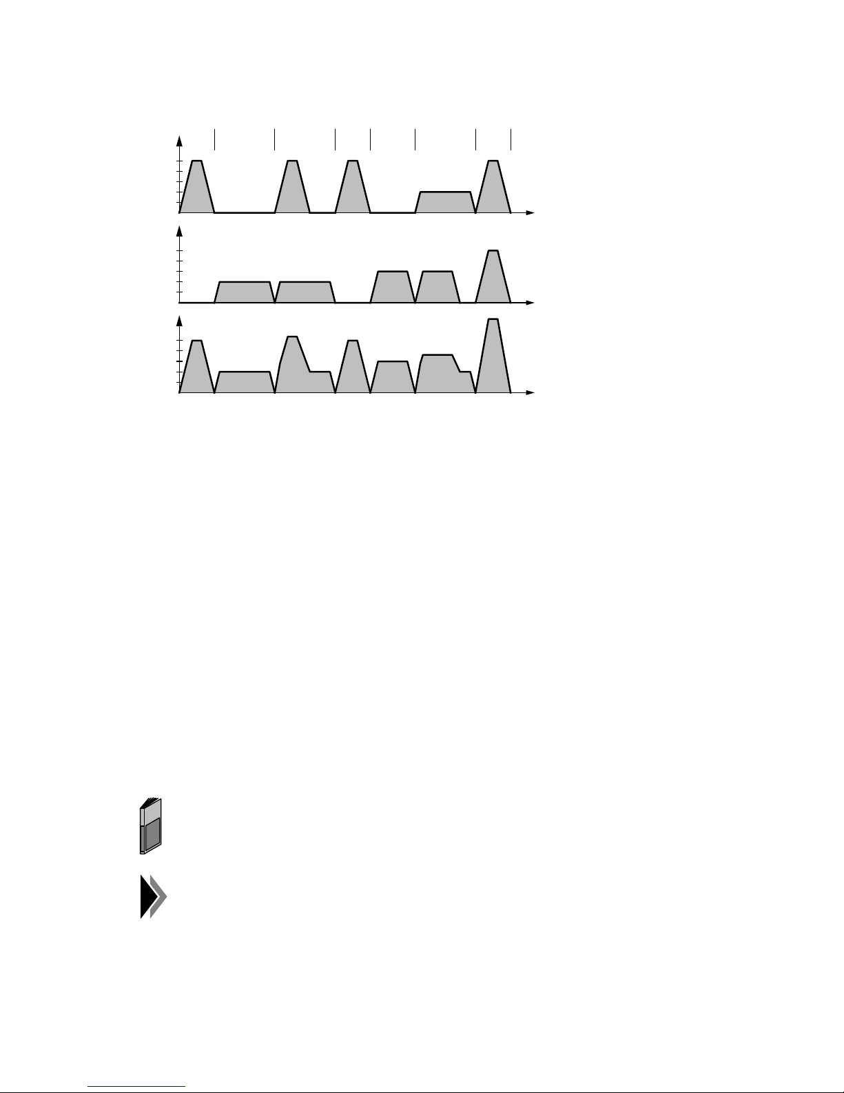
04.97 Programming of Traversing Blocks
v-t diagrams:
V
x
5000
N10 N20 N30
N40 N50 N60 N70
1000
V
5000
1000
V
Path
5000
1000
y
t
t
t
N10: The X-axis moves in absolute dimension G90 at its axis velocity FX5000.00 to
position X10.000.
N20: The Y-axis moves in absolute dimension G90 at its axis velocity FY2000.00 to
position Y10.000
N30 The X and Y-axes move together in absolute dimension to position X20.000/Y20.000,
each axis traversing at its own axis velocity FX5000.00/FY2000.00. As the X-axis has
to traverse the same distance, but moves at a higher axis velocity, it reaches its point
of destination earlier.
N40: The X-axis moves on in incremental dimension G91 by X10.000, at its axis velocity
FX5000.00. Furthermore, the Y-axis is assigned the new velocity value FY3000.00.
N50: The Y-axis moves on in incremental dimension G91 by Y10.000, at the new axis
velocity FY3000.00 assigned in N40. Furthermore, the X-axis is assigned the new
velocity value FX2000.00.
N60: The X and Y-axes move together in absolute dimension G90 to position
X40.000/Y40.000, at the axis velocities FX2000.00/FY3000.00. As the Y-axis has to
traverse the same distance, but moves at a higher axis velocity, it reaches its point of
destination earlier.
N70: The X and Y-axes move together in absolute dimension G90 at their new axis
velocities FX5000.00/FY5000.00 to position X50.000/Y50.000. As both axes traverse
the same distance at the same axis velocity, the path is a straight line.
In this example, "exact stop G60" is assumed to be the block transition
behaviour. In the chapter "block transitions", the different possibilities of
block transition are described in detail.
The programmed axis velocities refer to 100% override. Lower or higher
override values are taken into account in the axis velocities.
©
Siemens AG 1997 All Rights Reserved 6ZB5 440-0VU02
WF 723 C (Programming Guide)
4 – 9
Page 37
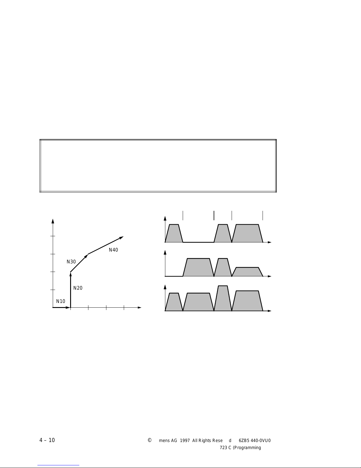
Programming of Traversing Blocks 04.97
aaaaa
a
a
a
a
aaaaa
a
a
a
a
a
a
a
aaaaa
a
a
a
a
aaaaa
a
a
a
a
4.7 Interpolation with rapid traverse G00
The path programmed with G00 "interpolation with rapid traverse" is traversed at the highest
possible speed along a straight line. The rapid traversing movements are programmed through
the preparatory function G00 and indication of the point of destination. The point of destination
can be specified in absolute dimension G90 or in incremental dimension G91.
If the rapid traversing movement is effected in several axes at the same time, the WF 723 C
will monitor the axes to make sure that none of the axes traverses at a higher velocity than its
maximum traversing speed (MD31).
The basic position is G00. G00 is modally effective. With "interpolation with rapid traverse",
one or two axes can be moved in rapid traverse along a straight line.
Programming:
N10 G90 (G00) X10.000
N20 Y20.000
N30 G91 X10.000 Y10.000
N40 G90 X40.000 Y40.000
Movement in the
coordinate system:
Y
40.
aaa
N30
aaa
aaa
a
aaa
a
N20
aaa
10.
aaa
N10
aaa
a
10. 40.
aaa
N40
aaa
v-t diagrams:
V
MD 31
V
MD 31
V
Path
X
N10 N20 N30
x
y
N40
t
t
t
4 – 10 ©
Siemens AG 1997 All Rights Reserved 6ZB5 440-0VU02
WF 723 C (Programming Guide)
Page 38

04.97 Programming of Traversing Blocks
N10: The X-axis moves in absolute dimension G90 in rapid traverse to position X10.000.
G00 need not be specified, as G00 is active in basic position.
N20: The Y-axis moves in absolute dimension G90 in rapid traverse to position Y20.000.
N30: The X and Y-axes move in incremental dimension G91 in rapid traverse to position
X10.000/Y10.000. As the two axes have to traverse the same distance, they can both
traverse at their maximum traversing speed (MD31).
N40: The X and Y-axes move in absolute dimension G90 in rapid traverse to position
X40.000/Y40.000. The X-axis has to traverse a longer distance and, therefore, moves
at maximum traversing speed. The Y-axis traverses a shorter distance and must,
therefore, reduce its velocity, so that it reaches its point of destination at the same
time as the X-axis.
In this example, "exact stop G60" is assumed to be the block transition
behaviour. In the chapter "block transitions", the different possibilities of
block transition are described in detail.
As for interpolation with rapid traverse, the override is effective, the
maximum traversing velocity is only reached with 100% override.
4.8 Interpolation with path velocity G01
The path programmed with G01 "interpolation with path velocity" is traversed at the
programmed path velocity along a straight line.
The "interpolation with path velocity" is programmed through the preparatory function G01,
indication of a point of destination, and the path velocity. The point of destination can be
specified in absolute dimension G90 or in incremental dimension G91.
G01 is modally effective. With "interpolation with path velocity", one or two axes can be
moved along a straight line.
©
Siemens AG 1997 All Rights Reserved 6ZB5 440-0VU02
WF 723 C (Programming Guide)
4 – 11
Page 39
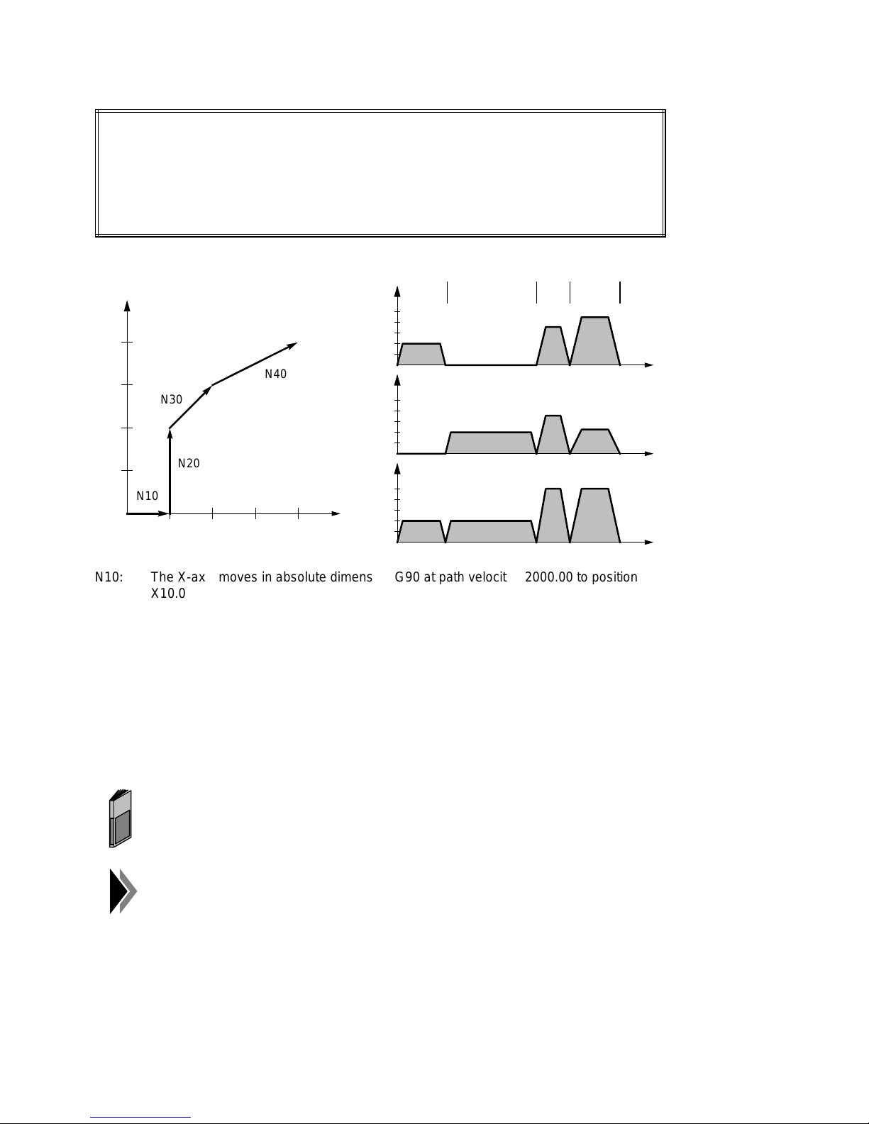
Programming of Traversing Blocks 04.97
aaaaa
a
a
a
a
a
aaaaa
a
a
a
a
a
aaaaa
a
a
a
a
aaaaa
a
a
a
a
a
Programming:
N10 G90 G01 X10.000 F2000.00
N20 Y20.000
N30 G91 X10.000 Y10.000 F5000.00
N40 G90 X40.000 Y40.000
Movement in the
coordinate system:
Y
v-t diagrams:
N10 N20 N30
x
5000
N40V
40.
1000
aaa
a
aaa
a
aaa
aaa
N30
N40
V
y
5000
V
y
1000
10.
a
aaa
a
N10
aaa
a
10. 40.
V
Path
5000
X
1000
aaa
a
N20
aaa
N10: The X-axis moves in absolute dimension G90 at path velocity F2000.00 to position
X10.000.
N20: The Y-axis moves in absolute dimension G90 at path velocity F2000.00 to position
Y20.000.
N30: The X and Y-axes move in incremental dimension G91 to position X10.000/Y10.000.
As the two axes have to traverse the same distance, they move at the same axis
velocities.
t
t
t
N40: The X and Y-axes move in absolute dimension G90 to position X40.000/Y40.000. The
X-axis has to traverse a longer distance, it traverses at a higher axis velocity than the
Y-axis.
In this example, "exact stop G60" is assumed to be the block transition
behaviour. In the chapter "block transitions", the different possibilities of
block transition are described in detail.
The programmed axis velocities refer to 100% override. Lower or higher
override values are taken into account in the axis velocities.
4 – 12 ©
Siemens AG 1997 All Rights Reserved 6ZB5 440-0VU02
WF 723 C (Programming Guide)
Page 40

04.97 Programming of Traversing Blocks
4.9 Synchronism
In the "synchronism" function, 2 or 3 axes traverse the same distance at the same time. The
synchronous axes can be monitored. With the synchronism monitoring activated, a comparison
of the actual values will stop the synchronous axes if a defined limit (synchronism tolerance) is
exceeded. With the WF 723 C, permanent or selectable synchronism is possible.
4.9.1 Permanent synchronism
In permanent synchronism, 2 or 3 axes are coupled by machine data. Master axis, slave
axis/axes, and the admissible synchronism tolerance are formulated. In the traversing program,
only the master axis is programmed. During program execution, the slave axis is firmly coupled
with the master axis.
Example: X-axis = master axis Z-axis = slave axis
Programming:
N10 X100.000
N20 X200.000 Y200.000
N10: X and Z-axes are traversed in synchronism to the positions X100.000 and Z100.000.
N20: The synchronizing axes X and Z are traversed together with the Y-axis to the
positions X200.000, Y200.000 and Z200.000.
4.9.2 Selectable synchronism
In selectable synchronism, there is no external coupling of the axes, coupling is effected in the
traversing program. The synchronism tolerance is defined by means of the command
"synchronism tolerance".
Programming:
N10 XZ100.000
N20 XZ200.000 Y200.000
N10: The synchronous axes X and Z are traversed to the positions X100.000 and
Z100.000. The axis which was programmed first, in this example the X-axis, is the
master axis, and the Z-axis is the slave axis.
N20: The synchronizing axes X and Z are traversed together with the Y-axis to the
positions X200.000, Y200.000 and Z200.000.
The program must not be started in the Z-axis, as the Z-axis is defined in
the traversing program as a slave axis.
©
Siemens AG 1997 All Rights Reserved 6ZB5 440-0VU02
WF 723 C (Programming Guide)
4 – 13
Page 41
Programming of Traversing Blocks 04.97
4.9.3 Tracking synchronism (G79)
In tracking synchronism G79, the slave axes are moved to the position of the master axis. G79
is effective block by block.
Programming:
N10 G01 G79 X(Y)1234.000 F1000.00
N20 X(Y)2000.000
N10: If the Y-axis (slave axis) is not in the same position as the master axis, the Y axis will
be traversed at speed F1000.000 to the position of the master axis. The position
value X(Y)1234.000 only serves for selecting the axis/axes. If the Y-axis is already in
the position of the master axis, N10 will be ignored.
N20: The synchronous axes X and Z are traversed together to X(Y)2000.000.
Synchronism monitoring must only be switched on when the axes have
been synchronized.
4 – 14 ©
Siemens AG 1997 All Rights Reserved 6ZB5 440-0VU02
WF 723 C (Programming Guide)
Page 42
04.97 Programming of Traversing Blocks
4.9.4 Synchronism in combination with interpolation and chaining
Programming:
N10 G00 X(Z)100.000 Y100.000
N20 G01 X(Z)200.000 Y300.000 F1000.00
N30 G76 X(Z)300.000 Y400.000
N40 G77 X(Z)400.000 Y800.000 FX1000.00 FY2000.00
(Z) In case of permanent synchroism, Z is not indicated
N10: Interpolation with rapid traverse
There is an interpolation between the X and Y-axes. The Z-axis follows the X-axis.
The resulting axis velocities are determined in such a way that all axes traverse at
their maximum velocity along a straight line.
N20: Interpolation with path velocity
There is an interpolation between the X and Y-axes. The partial velocities are
determined for the X and Y-axes. The Z-axis traverses at the velocity of the X-axis.
If the partial velocity calculated for the X-axis is higher than the admissible maximum
velocity (MD31) for the Z-axis, all partical velocities are reduced so far that,
nevertheless, an interpolation straight line can be traversed without violating any axis
velocities.
N30: Chaining with rapid traverse
The Y-axis traverses with its maximum velocity (MD31). At the same time, the X and
Z-axis traverse with the velocity of the MD31 of the slower axis.
N40: Chaining with axis velocity
The synchronous axes traverse with the axis velocity FX1000.00 and at the same
time, the Y-axis moves to its position with FY2000.00.
Make sure that in synchronism the axis programmed first determines at the
same time which axis speed is used.
©
Siemens AG 1997 All Rights Reserved 6ZB5 440-0VU02
WF 723 C (Programming Guide)
4 – 15
Page 43
Programming of Traversing Blocks 04.97
aaaaaaaaaaaaaaaaaaaaaaaaaaaaaaaaaaaaaaaaaaaaaaaaaaaaaaaaaaaaaaaaaaaaaaaaaaaaaaaaaaaaaaaaaaaaaaaaaaaaaaaaaaaaaaa
a
a
a
a
a
a
a
a
a
a
4.10 Collision monitoring (G96, G97)
By means of the collision monitoring function, the axes can quickly be stopped, triggered by
the selection of a rapid input.
G96: Selection of collision monitoring
When reading in a traversing block with G96, collision monitoring will be activated
➯ release of the inquiry of the rapid input.
G97: Deselection of collision monitoring
When reading in a traversing block with G97, collision monitoring will be deactivated
➯ the rapid input will no longer be inquired.
In basic position, G97 is active. G96 and G97 are modally effective.
4.10.1 Specifying a deceleration value
With the "Deceleration at collision" command, the braking deceleration of the axis in case of
collision can be specified. For each axis, a separate value can be specified, the lower input
limit being limited by MD 28 (deceleration).
aaaaaaaaaaaaaaaaaaaaaaaaaaaaaaaaaaaaaaaaaaaaaaaaaaaaaaaaaaaaaaaaaaaaaaaaaaaaaaaaaaaaaaaaaaaaaaaaaaaaaaaaaaaaa
aaaaaaaaaaaaaaaaaaaaaaaaaaaaaaaaaaaaaaaaaaaaaaaaaaaaaaaaaaaaaaaaaaaaaaaaaaaaaaaaaaaaaaaaaaaaaaaaaaaaaaaaaaaaa
aaaaaaaaaaaaaaaaaaaaaaaaaaaaaaaaaaaaaaaaaaaaaaaaaaaaaaaaaaaaaaaaaaaaaaaaaaaaaaaaaaaaaaaaaaaaaaaaaaaaaaaaaaaaa
Designation Lower limit Upper limit Unit
aaaaaaaaaaaaaaaaaaaaaaaaaaaaaaaaaaaaaaaaaaaaaaaaaaaaaaaaaaaaaaaaaaaaaaaaaaaaaaaaaaaaaaaaaaaaaaaaaaaaaaaaaaaaa
aaaaaaaaaaaaaaaaaaaaaaaaaaaaaaaaaaaaaaaaaaaaaaaaaaaaaaaaaaaaaaaaaaaaaaaaaaaaaaaaaaaaaaaaaaaaaaaaaaaaaaaaaaaaa
Deceleration at collision MD 28 99 999
mm/s
The commands are described in the Planning Guide "Command identifiers
for SIMATIC S5 and S7" under AK15 (Options).
4.10.2 Specifying a rapid input
For collision monitoring, a rapid input must be specified with the "Collision" function in MD 15
(rapid inputs).
The rapid input must be preset in MD 15 of the master axis in which the
traversing program is started.
2
The parameterization of the rapid inputs is described in the Description of
Functions, chapter "Rapid inputs/outputs".
4 – 16 ©
Siemens AG 1997 All Rights Reserved 6ZB5 440-0VU02
WF 723 C (Programming Guide)
Page 44
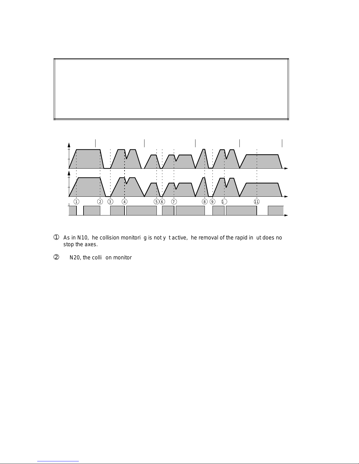
04.97 Programming of Traversing Blocks
a
a
a
a
a
a
a
a
aaa
aaa
aaa
aaa
a
a
a
a
a
a
a
a
a
a
a
a
a
a
a
a
a
a
a
a
a
a
a
a
a
a
a
a
a
a
a
a
a
a
a
a
a
a
a
a
aaa
aaa
aaa
aaa
a
a
a
a
a
a
a
a
aaa
aaa
aaa
aaa
aaa
aaa
aaa
aaa
a
a
a
a
a
a
a
a
4.10.3 Collision monitoring - Example
Programming:
N10 G77 X100.000 Y100.000 FX1000.00 FY1000.00
N20 G96 X200.000 Y200.000
N30 G01 X300.000 Y300.000 F1000.00
N40 XY400.000
N50 G97 X500.000 Y500.000
v-t diagrams:
N10 N20
x
N30V
N40
N50
1000
V
y
1000
1
1
E
2
2
3
4
5
6
7
9
8
10
11
0
➀
As in N10, the collision monitoring is not yet active, the removal of the rapid input does not
stop the axes.
➁
In N20, the collision monitoring is activated with G96. As chaining is active, the removal of
the rapid input stops the axes with the "deceleration at collision" specified for the
respective axis.
➂
Upon selection of the rapid input, the axes are accelerated with the acceleration values
(MD 27).
➃
If the rapid input is removed for a short time only, the axes will be braked with
"deceleration at collision". Then, traversing will be continued with the acceleration values
(MD 27).
t
t
t
➄
In N30, the interpolation is switched on. When the rapid input is removed, the axes stop,
observing the interpolation conditions (the contour must not be left), i.e. the "deceleration
at collision" of the "weaker" axis (lower deceleration value) is taken into consideration as
the maximally admissible deceleration (in this case axis Y).
➅
Upon selection of the rapid input, the axes are accelerated with the acceleration values
(MD 27).
➆
If the rapid input is removed for a short time only, the axes will be braked with the
"deceleration at collision" of the "weaker" axis, observing the interpolation conditions.
Then, traversing will be continued with the acceleration values (MD 27).
©
Siemens AG 1997 All Rights Reserved 6ZB5 440-0VU02
WF 723 C (Programming Guide)
4 – 17
Page 45

Programming of Traversing Blocks 04.97
➇
In N40, tracking is selected. When the rapid input is removed, the axes stop, observing the
tracking conditions (the axes must not move apart), i.e. the "deceleration at collision" of
the "weaker" axis (lower deceleration value) is taken into consideration as the maximally
admissible deceleration (in this case axis X).
➈
Upon selection of the rapid input, the axes are accelerated with the acceleration values
(MD 27).
➉
If the rapid input is removed for a short time only, the axes will be braked with the
"deceleration at collision" of the "weaker" axis, observing the tracking conditions. Then,
traversing will be continued with the acceleration values (MD 27).
As in N50, collision monitoring is deselected via G97, a removal of the rapid input will not
11
stop the axes.
4 – 18 ©
Siemens AG 1997 All Rights Reserved 6ZB5 440-0VU02
WF 723 C (Programming Guide)
Page 46
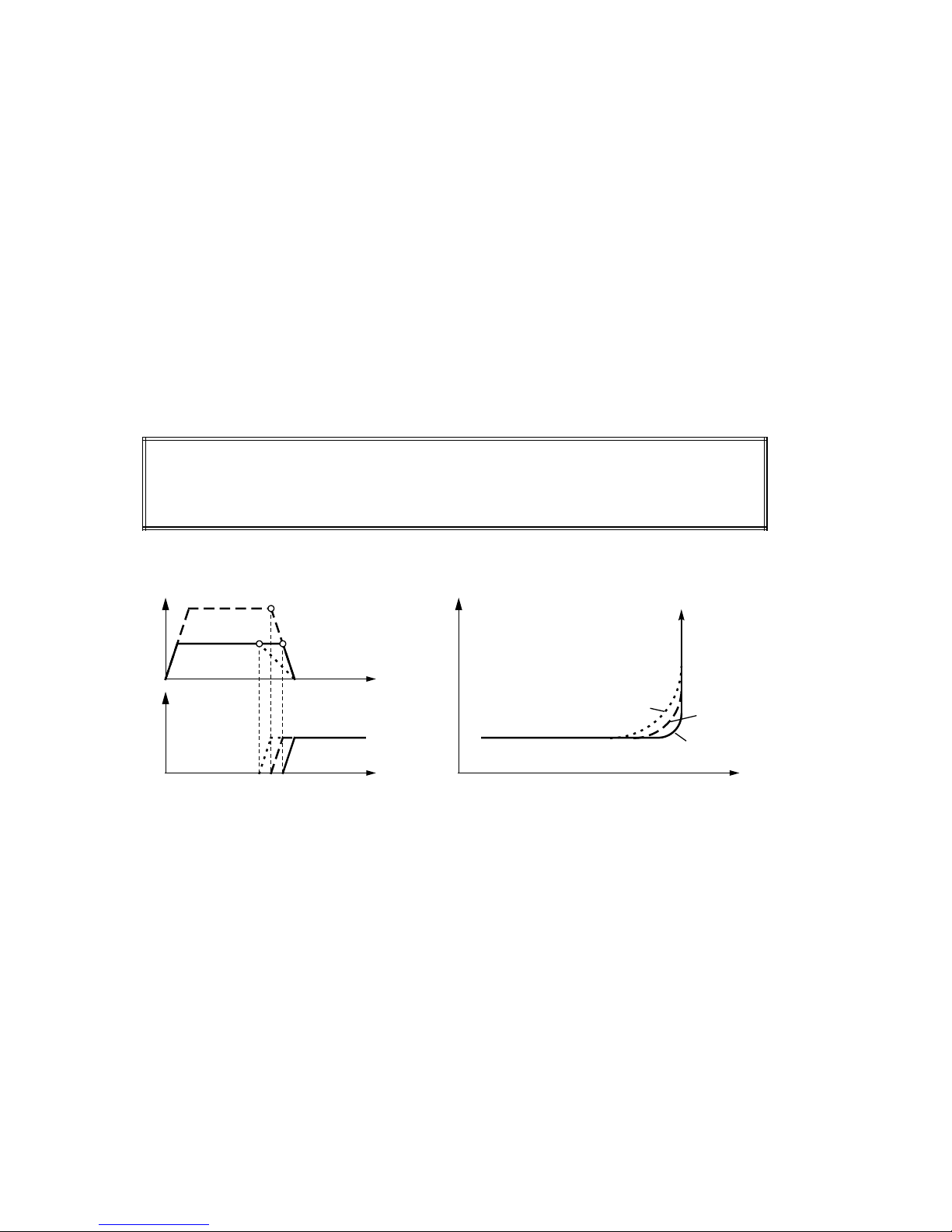
04.97 Programming of Traversing Blocks
4.11 Block transitions
Traversing programs are executed according to the programmed sequence of traversing
blocks. Depending on the contents of the traversing blocks, there are various block transitions.
4.11.1 Maximum loop-over G64
G64 is active in basic position. G64 is modally effective. Maximum loop-over means that
consecutive movement blocks are traversed in the shortest time possible and with the smallest
speed reductions possible. In this way, very fast sequences of movements are possible.
The so-called braking point is of great importance for the block transition; it determines the
earliest possible moment of a block change. The braking point is the moment when an axis
would have to start braking in order to stop at the programmed point of destination or slow
down to the new velocity. Therefore, this braking point depends on the selected deceleration
(braking ramp) and the current velocity.
Programming:
N10 X100.000
N20 Y100.000
Loop-over behaviour with
different braking points
➂
➁
➀
F
x
F
y
➀
Braking point at low speed ➯ small loop-over
➁
Braking point at high speed ➯ larger loop-over
➂
Braking point with flat braking ramp ➯ large loop-over
Coordinate system
Y
➂
➁
➀
X
©
Siemens AG 1997 All Rights Reserved 6ZB5 440-0VU02
WF 723 C (Programming Guide)
4 – 19
Page 47
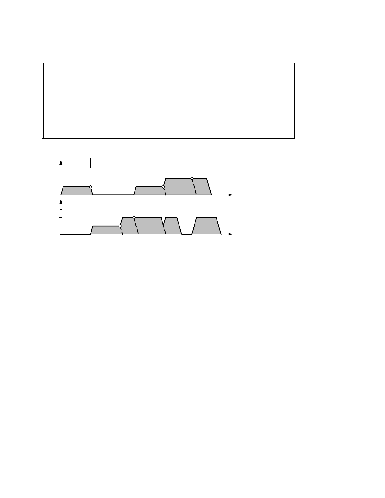
Programming of Traversing Blocks 04.97
• Chaining (G76, G77) with maximum loop-over (G64)
Programming:
N10 G90 G77 X100.000 FX1000.00
N20 Y100.000 FY1000.00
N30 Y200.000 FY2000.00
N40 X200.000 Y385.000
N50 X400.000 Y485.000 FX2000.00
N60 X500.000 Y650.000
v-t diagrams:
x
3000
1000
V
y
3000
1000
N10 N20 N30
N40V
N50 N60
t
t
N10: The X-axis moves with velocity FX1000.00 to position X100.000.
N20: In the braking point of the X-axis, the Y-axis is started and moves with velocity
FY1000.00 in the direction of position Y100.000.
N30: At the braking point, the Y-axis accelerates to its new velocity FY2000.00.
N40: While the Y-axis approaches the new position Y385.000 without speed reduction, the
X-axis is started. As this axis needs more time to reach its point of destination, the Y-
axis starts to brake.
N50: The X and Y-axes accelerate to their respective velocities. As the Y-axis reaches its
destination earlier, it stops in its position and waits until the X-axis has reached its
braking point.
N60: At the braking point of the X-axis, the Y-axis accelerates again. The two axes move
up to their destinations and stop.
4 – 20 ©
Siemens AG 1997 All Rights Reserved 6ZB5 440-0VU02
WF 723 C (Programming Guide)
Page 48
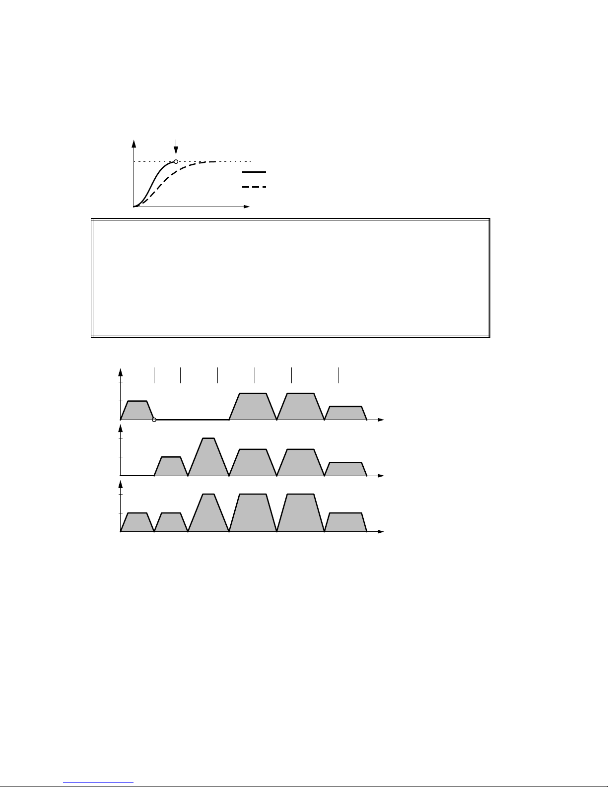
04.97 Programming of Traversing Blocks
• Interpolation (G00, G01) with maximum loop-over (G64)
With interpolation, a loop-over in the braking point is not possible because the axis must
not leave the programmed contour. With interpolation, G64 always traverses to "digital
zero".
S
Digital zero
Programming:
N10 G90 G01 X100.000 F1000.00
N20 Y100.000
N30 Y300.000 F2000.00
N40 X300.000 Y500.000
N50 X500.000 Y700.000
N60 X600.000 Y800.000 F1000.00
v-t diagrams
V
x
2000
1000
V
y
2000
N10 N20 N30
N40
Nominal curve
Actual curve
N50 N60
Traversing to "digital zero" means
that the interpolator must have
reached the programmed position.
t
1000
V
Bahn
2000
1000
t
t
N10: The X-axis moves with velocity F1000.00 to position X100.000.
N20: At "digital zero" of the X-axis, the Y-axis is started and moves with velocity F1000.00
to position Y100.000.
N30: At "digital zero", the Y-axis accelerates to the new velocity F2000.00.
N40: At "digital zero" of the Y-axis, the X and Y-axis accelerate with interpolation to their
path velocity F2000.00.
N50: Block change is again effected at "digital zero".
N60: At "digital zero", the X and Y-axes traverse at the new path velocity F1000.00 to
positions X600.000 Y800.000.
©
Siemens AG 1997 All Rights Reserved 6ZB5 440-0VU02
WF 723 C (Programming Guide)
4 – 21
Page 49
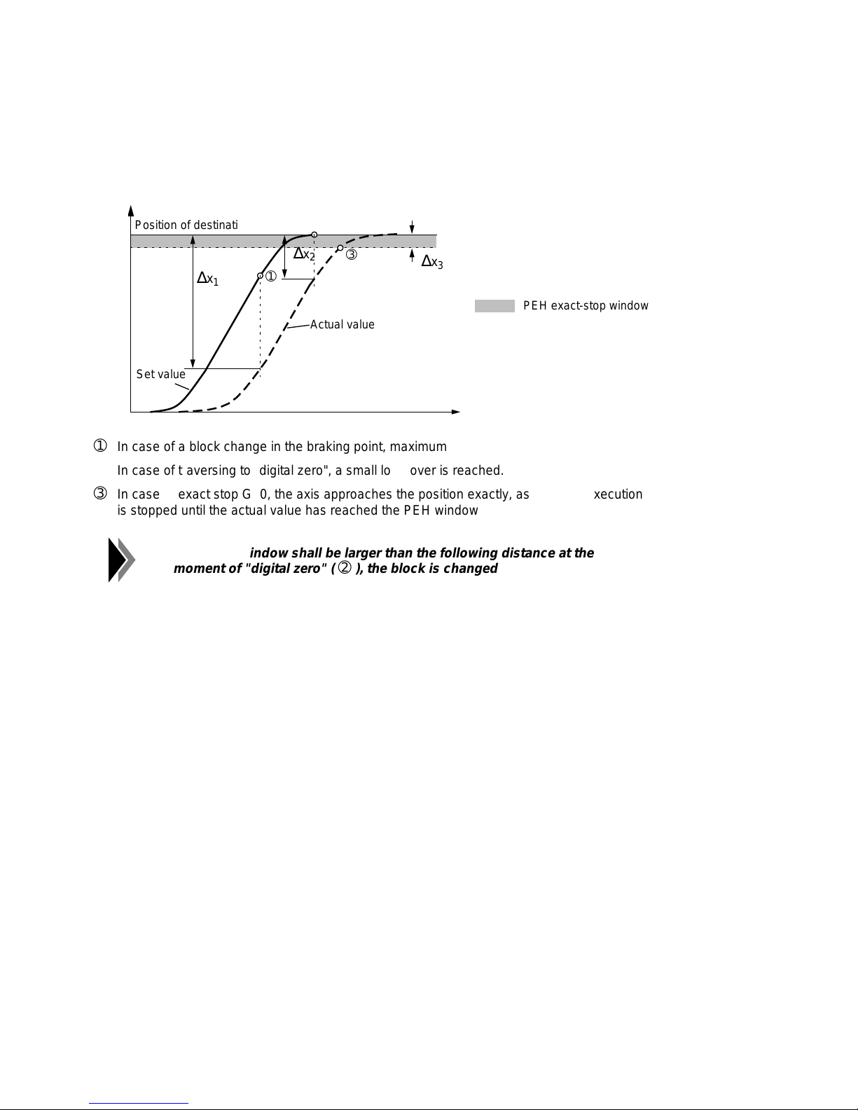
Programming of Traversing Blocks 04.97
aaaaa
a
a
a
a
a
aaaaaaaaaaaaaaaaaaaaaaaaaaa
a
a
a
a
aaa
aaa
aaa
aaa
aaa
aaa
aaaaa
a
a
a
a
a
a
aaaaa
a
a
a
a
aaa
aaa
aaa
aaaaaaaaaaa
a
a
a
a
a
aaaaaaaaaaaaaaaaa
a
a
a
a
aaaaaaaaaaaaaaaaaaaaaaaaaaa
a
a
a
a
4.11.2 Exact stop G60
If programmed positions shall be approached exactly, exact stop G60 has to be programmed.
G60 is modally effective. When G60 has been programmed, program execution is stopped
until all axes involved have reached their respective PEH window.
S
aaaaaaaaaaaaaaaaaaaaaaaaa
Position of destination
aaaaaaaaaaaaaaaaaaaaaaaaa
aaa
aaa
∆
x
1
aaa
➀
➁
aaa
aaa
∆
x
aaa
➂
2
aaaaaaaaaaaaaaa
aaaaaaaaaaaaaaa
Actual value
aaa
a
∆
x
aaa
a
3
aaaaaaaaaaaaaaaaaaaaaaaaa
PEH exact-stop window
aaaaaaaaaaaaaaaaaaaaaaaaa
aaaaaaaaa
aaaaaaaaa
Set value
a
a
t
➀
In case of a block change in the braking point, maximum loop-over takes place.
➁
In case of traversing to "digital zero", a small loop-over is reached.
➂
In case of exact stop G60, the axis approaches the position exactly, as program execution
is stopped until the actual value has reached the PEH window.
If the PEH window shall be larger than the following distance at the
moment of "digital zero" (
➁
), the block is changed at "digital zero".
4 – 22 ©
Siemens AG 1997 All Rights Reserved 6ZB5 440-0VU02
WF 723 C (Programming Guide)
Page 50
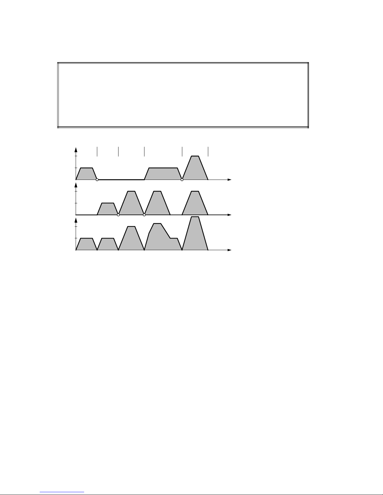
04.97 Programming of Traversing Blocks
• Chaining (G76, G77) with exact stop (G60)
Programming:
N10 G90 G77 G60 X100.000 FX1000.00
N20 Y100.000 FY1000.00
N30 Y300.000 FY2000.00
N40 X300.000 Y500.000
N50 X500.000 Y700.000 FX2000.00
v-t diagrams:
V
x
2000
1000
N10 N20 N30
N40
N50
V
y
2000
1000
V
Path
2000
1000
t
t
t
N10: The X-axis moves with velocity FX1000.00 to position X100.000.
N20: As soon as the X-axis has reached its PEH window, the Y-axis moves to position
Y100.000.
N30: When the Y-axis has reached its PEH window, it moves on to position Y300.000.
N40: When the Y-axis has reached its PEH window, the X and Y-axes move to positions
X300.000 and Y500.000. As the Y-axis reaches its destination earlier, it stops and
waits for the X-axis.
N50: When the two axes have reached their respective PEH window, they traverse to their
new positions X500.000 and Y700.000.
©
Siemens AG 1997 All Rights Reserved 6ZB5 440-0VU02
WF 723 C (Programming Guide)
4 – 23
Page 51
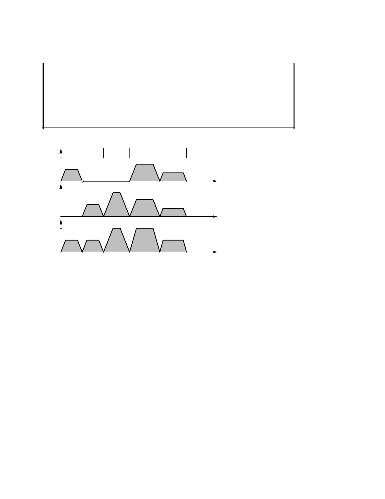
Programming of Traversing Blocks 04.97
• Interpolation (G00, G01) with exact stop (G60)
Programming:
N10 G90 G01 G60 X100.000 F1000.00
N20 Y100.000
N30 Y300.000 F2000.00
N40 X300.000 Y500.000
N50 X400.000 Y600.000 F1000.00
v-t diagrams:
V
x
N10 N20 N30
2000
1000
N40
N50
V
2000
1000
V
2000
1000
y
Path
t
t
t
N10: The X-axis moves with velocity F1000.00 to position X100.000.
N20: As soon as the X-axis has reached its PEH window, the Y-axis moves to position
Y100.000.
N30: When the Y-axis has reached its PEH window, it moves on to position Y300.000.
N40: When the Y-axis has reached its PEH window, the X and Y-axes move with
interpolation to positions X300.000 and Y500.000.
N50: When the X and Y-axes have reached their PEH windows, they move on to positions
X400.000 and Y600.000.
4 – 24 ©
Siemens AG 1997 All Rights Reserved 6ZB5 440-0VU02
WF 723 C (Programming Guide)
Page 52
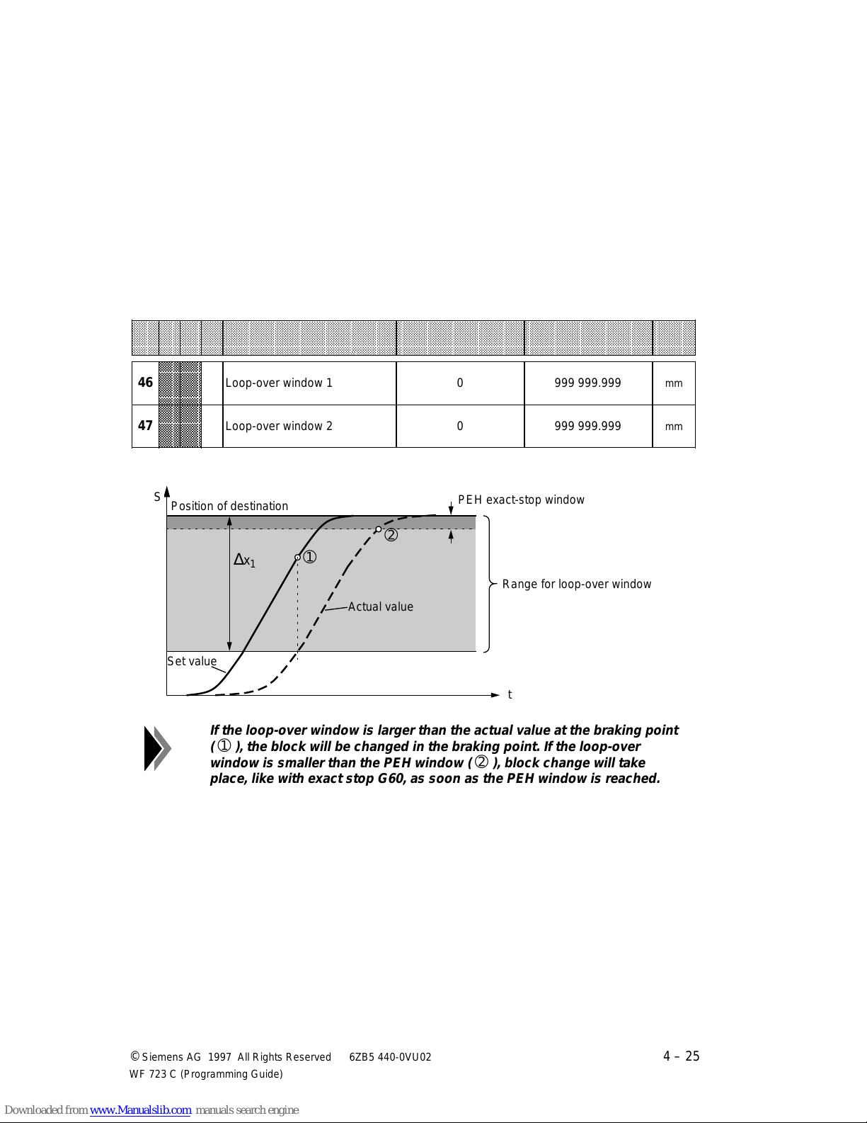
04.97 Programming of Traversing Blocks
aaaaaaaaaaaaaaaaaaaaaaaaaaaaaaaaaaaaaaaaaaaaaaaaaaaaaaaaaaaaaaaaaaaaaaaaaaaaaaaaaaaaaaaaaaaaaaaaaaaaaaaaaaaaaaa
a
a
a
a
a
a
a
a
a
a
a
a
a
aaaaaaaaa
a
a
a
a
a
a
a
a
a
a
a
a
a
a
a
a
a
a
a
a
a
a
a
a
a
a
a
a
a
a
a
a
aaaaaaaaaaa
a
a
a
a
aaaaaaaaaaaaaaaaaaaaaaaaaaa
a
a
a
a
aaa
a
a
a
a
a
aaaaa
a
a
a
a
a
aaa
a
a
a
a
a
a
a
aaaaaaaaaaaaaaaaa
a
a
a
a
aaaaaaaaaaaaaaaaaaaaaaaaaaa
a
a
a
a
aaaaaaaaaaaaaaaaaaaaaaaaaaaaaaa
a
a
a
a
a
a
4.11.3 Loop-over window 1 or 2 (G66, G67)
Block change at the braking point G64 leads to fast sequences of movements, but the large
loop-over results in a great deviation from the programmed path. Block change with exact stop
G60 guarantees that the positions are exactly reached, but the positioning time is increased
because sequences of movements are again and again passed to the PEH window and,
therefore, stopped.
For a more flexible programming, the WF 723 C offers two loop-over windows. For loop-over,
two dimensions can be defined, which lie between the braking point
G66 activates the loop-over window 1 (MD46), G67, the loop-over window 2 (MD47). G66 and
G67 are modally effective.
➀
and the exact stop ➁.
aaaaaaaaaaaaaaaaaaaaaaaaaaaaaaaaaaaaaaaaaaaaaaaaaaaaaaaaaaaaaaaaaaaaaaaaaaaaaaaaaaaaaaaaaaaaaaaaaaaaaaaaaaaaa
aaaaaaaaaaaaaaaaaaaaaaaaaaaaaaaaaaaaaaaaaaaaaaaaaaaaaaaaaaaaaaaaaaaaaaaaaaaaaaaaaaaaaaaaaaaaaaaaaaaaaaaaaaaaa
MD
aaaaaaaaaaaaaaaaaaaaaaaaaaaaaaaaaaaaaaaaaaaaaaaaaaaaaaaaaaaaaaaaaaaaaaaaaaaaaaaaaaaaaaaaaaaaaaaaaaaaaaaaaaaaa
I SSI W Designation Lower limit Upper limit Unit
aaaaaaaaaaaaaaaaaaaaaaaaaaaaaaaaaaaaaaaaaaaaaaaaaaaaaaaaaaaaaaaaaaaaaaaaaaaaaaaaaaaaaaaaaaaaaaaaaaaaaaaaaaaaa
aaaaaaaaaaaaaaaaaaaaaaaaaaaaaaaaaaaaaaaaaaaaaaaaaaaaaaaaaaaaaaaaaaaaaaaaaaaaaaaaaaaaaaaaaaaaaaaaaaaaaaaaaaaaa
No.
aaaaaaaaaaaaaaaaaaaaaaaaaaaaaaaaaaaaaaaaaaaaaaaaaaaaaaaaaaaaaaaaaaaaaaaaaaaaaaaaaaaaaaaaaaaaaaaaaaaaaaaaaaaaa
aaaaaaa
aaaaaaa
aaaaaaa
aaaaaaa
46
aaaaaaa
aaaaaaa
aaaaaaa
aaaaaaa
aaaaaaa
aaaaaaa
aaaaaaa
aaaaaaa
aaaaaaa
47
aaaaaaa
aaaaaaa
aaaaaaa
S
aaaaaaaaaaaaaaaaaaaaaaaaa
aaaaaaaaaaaaaaaaaaaaaaaaa
Position of destination
aaaaaaaaa
Set value
aaaaaaaaa
Loop-over window 1 0 999 999.999
Loop-over window 2 0 999 999.999
aaaaaaaaaaaaaaaaaaaaaaaaa
PEH exact-stop window
aaaaaaaaaaaaaaaaaaaaaaaaa
a
a
a
a
➁
a
aaa
a
∆
x
aaa
a
1
➀
a
a
a
a
a
aaaaaaaaaaaaaaa
Actual value
aaaaaaaaaaaaaaa
aaaaaaaaaaaaaaaaaaaaaaaaaaaaa
aaaaaaaaaaaaaaaaaaaaaaaaaaaaa
Range for loop-over window
aaaaaaaaaaaaaaaaaaaaaaaaaaaaa
mm
mm
t
If the loop-over window is larger than the actual value at the braking point
➀
), the block will be changed in the braking point. If the loop-over
(
window is smaller than the PEH window (
➁
), block change will take
place, like with exact stop G60, as soon as the PEH window is reached.
a
a
a
a
a
a
©
Siemens AG 1997 All Rights Reserved 6ZB5 440-0VU02
WF 723 C (Programming Guide)
4 – 25
Page 53
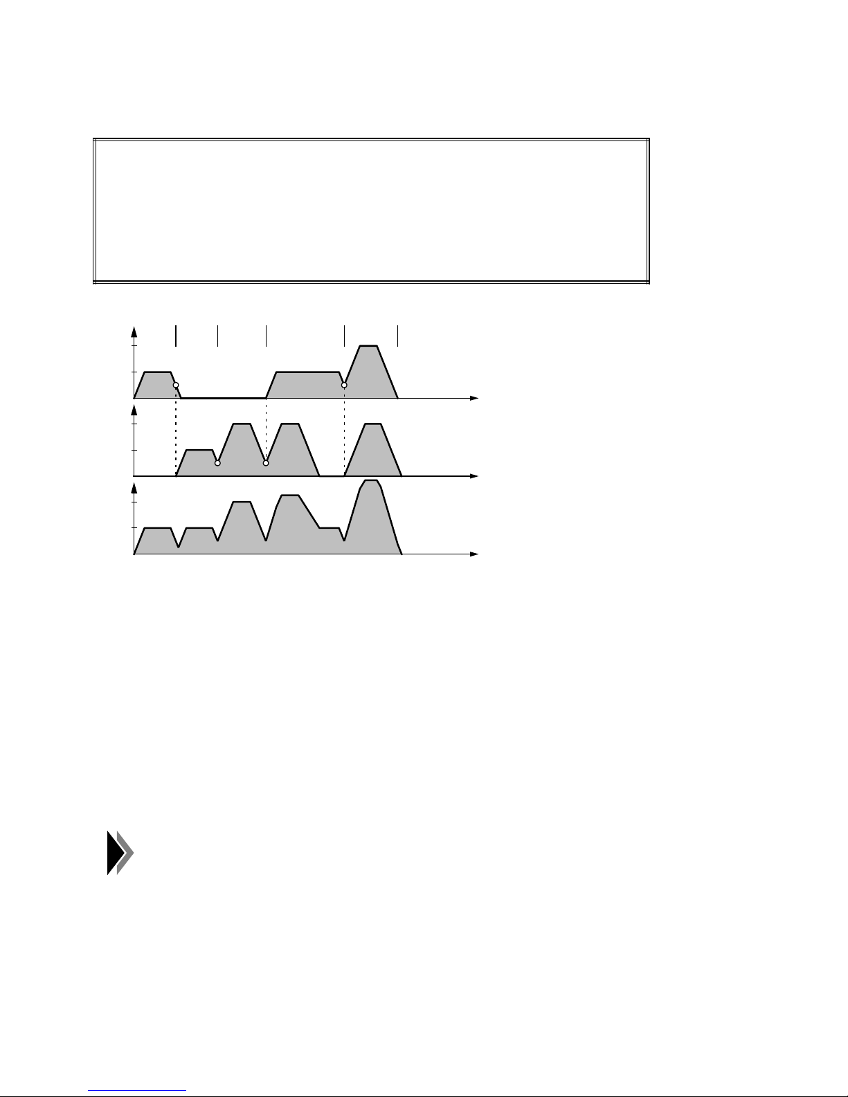
Programming of Traversing Blocks 04.97
• Chaining (G76, G77) with loop-over (G66, G67)
Programming:
N10 G90 G77 G66 X100.000 FX1000.00
N20 Y100.000 FY1000.00
N30 Y300.000 FY2000.00
N40 X300.000 Y500.000
N50 X500.000 Y700.000 FX2000.00
v-t diagrams:
V
x
N10 N20 N30
2000
1000
N40
N50
V
2000
1000
V
2000
1000
y
Path
t
t
t
N10: The X-axis moves with velocity FX1000.00 to position X100.000.
N20: As no axis change takes place at the change-over from N20 to N30, i.e. the loop-
over refers to the same axis, looping over is effected without a sudden velocity drop
(as with G64).
N30: After the velocity of the Y-axis has been reduced so far that the actual value has
reached the loop-over window 1, the Y-axis is accelerated again.
N40: In the loop-over window 1 of the Y-axis, the X-axis is additionally started. The X and
Y-axes move together to positions X300.000 and Y300.000. As the X-axis needs
more time for its path, the Y-axis stops.
N50: In the loop-over window 1 of the X-axis, the Y-axis is additionally started.
• Interpolation (G00, G01) with loop-over (G66, G67)
With interpolation, a loop-over in loop-over window 1/2 is only possible if
the loop-over window 1/2 is smaller than the loop-over value for "digital
zero". It is, therefore, not possible to enlarge the loop-over behaviour
beyond "digital zero" through a correspondingly large loop-over window.
4 – 26 ©
Siemens AG 1997 All Rights Reserved 6ZB5 440-0VU02
WF 723 C (Programming Guide)
Page 54
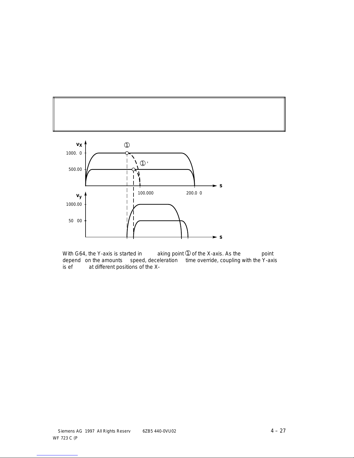
04.97 Programming of Traversing Blocks
aaa
a
a
a
a
a
aaa
aaa
aaa
aaa
a
a
a
a
a
aaaaaaaaa
a
a
a
a
aaaaaaaaa
a
a
a
a
aaa
aaa
aaa
aaa
a
a
a
a
a
aaaaa
a
a
a
a
aaaaaaaaa
a
a
a
a
a
a
aaaaaaa
a
a
a
a
a
aaaaaaaaa
a
a
a
a
aaaaaaa
a
a
a
a
a
4.11.4 Path-dependent chaining (G63)
For certain applications it is necessary to start an axis independently of the current position of
another axis, without stopping the latter. This can be realized by the function of pathdependent chaining G63. G63 is modally effective.
• Programming with G64 (maximum loop-over)
Programming:
N10 G77 G64 X100.000 FX1000.00 (FX500.00)
N20 X200.000 Y100.000 FY1000.00 (FY500.00)
a
v
aaaaaaa
aaaaaaa
1000.00
aaaaaaa
aaaaa
aaaaa
500.00
v
aaaaaaa
1000.00
aaaaaaa
a
a
a
X
a
a
a
a
a
a
y
➀
a
a
a
a
aaa
➀
'
aaa
s
aaaaaaa
100.000
aaaaaaa
aaaaaaa
200.000
aaaaaaa
aaaaa
a
500.00
aaaaa
a
s
With G64, the Y-axis is started in the braking point ➀ of the X-axis. As the braking point
depends on the amounts of speed, deceleration or time override, coupling with the Y-axis
is effected at different positions of the X-axis.
©
Siemens AG 1997 All Rights Reserved 6ZB5 440-0VU02
WF 723 C (Programming Guide)
4 – 27
Page 55
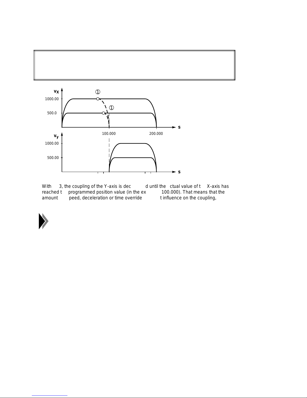
Programming of Traversing Blocks 04.97
aaa
a
a
a
a
a
aaa
aaa
aaa
aaaaa
a
a
a
a
a
a
aaaaaaaaa
a
a
a
a
aaa
aaa
aaa
aaa
a
a
a
a
a
aaaaa
a
a
a
a
aaaaaaaaa
a
a
a
a
aaaaaaa
a
a
a
a
a
a
aaaaaaaaa
a
a
a
a
aaaaaaa
a
a
a
a
• Programming with G63 (path-dependent chaining)
Programming:
N10 G77 G63 X100.000 FX1000.00 (FX500.00)
N20 X200.000 Y100.000 FY1000.00 (FY500.00)
v
aaaaaaa
1000.00
aaaaaaa
aaaaa
aaaaa
500.00
aaaaa
aaa
aaa
X
aaa
➀
a
a
a
a
aaa
➀
'
aaa
s
aaaaaaa
v
aaaaaaa
aaaaaaa
1000.00
aaaaa
500.00
aaaaa
a
a
a
a
y
100.000
200.000
aaaaaaa
s
With G63, the coupling of the Y-axis is decelerated until the actual value of the X-axis has
reached the programmed position value (in the example: 100.000). That means that the
amounts of speed, deceleration or time override have not influence on the coupling, so
that coupling can only be delayed by the WF cycle time (2 ms).
The function G63 is derived from G64, i.e. if path-dependent chaining is
not possible, G63 will have the same effect as G64.
4 – 28 ©
Siemens AG 1997 All Rights Reserved 6ZB5 440-0VU02
WF 723 C (Programming Guide)
Page 56
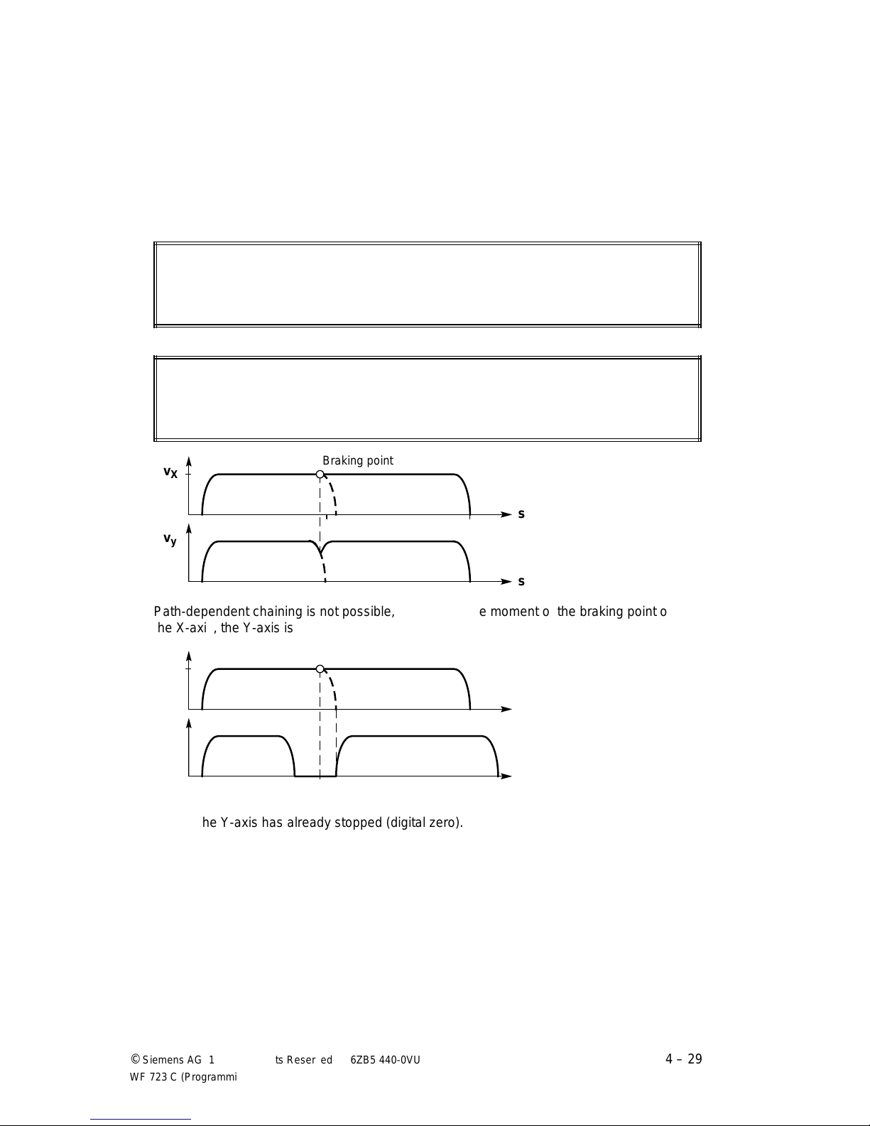
04.97 Programming of Traversing Blocks
aaaaaaaaaaaaaaa
a
a
a
a
a
a
a
a
a
a
a
a
aaaaa
a
a
a
a
a
a
a
a
a
a
aaa
a
a
a
a
a
aaaaaaaaaaaaaaa
a
a
a
a
Braking point
a
a
a
a
a
a
s
aaaaa
a
a
a
a
v
X
a
a
a
a
a
a
s
aaa
a
a
a
a
a
v
y
Under the following circumstandes, path-dependent chaining is not possible:
• in case of interpolation (G00, G01)
• in case of switchover between interpolation, chaining and synchronization
(see section 4.11.5)
• if the special functions "flying actual-value setting" and "external block change" are used
• if exclusively other axes are used in the next traversing block
Programming (G63 has the same effect as G64):
N10 G76 G63 X100.000 Y100.000
N20 Z100.000
• if at the moment of block change (braking point) all programmed axes are moving
Programming:
N10 G76 G63 X... Y...
N20 X... Y...
aaaaaaaaaaaaa
Braking point
aaa
v
aaa
X
aaaaaaaaaaaaa
s
a
a
a
a
v
y
s
Path-dependent chaining is not possible, because at the moment of the braking point of
the X-axis, the Y-axis is still moving (➯ G63 has the same effect as G64).
aaaaaaaaaaaaa
aaa
aaa
a
a
a
a
aaaaaaaaaaaaa
Path-dependent chaining is effected, because at the moment of the braking point of the
X-axis, the Y-axis has already stopped (digital zero).
©
Siemens AG 1997 All Rights Reserved 6ZB5 440-0VU02
WF 723 C (Programming Guide)
4 – 29
Page 57
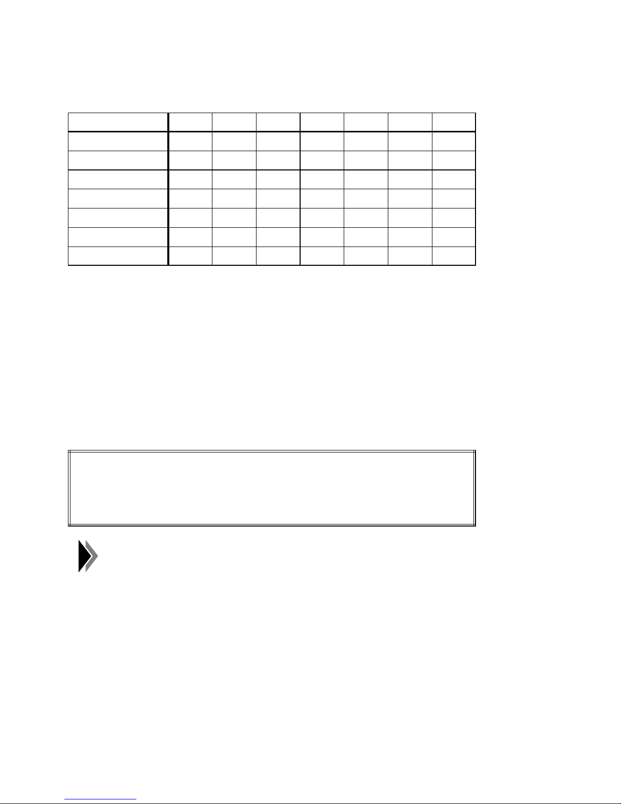
Programming of Traversing Blocks 04.97
The following table shows the many possible combinations of block transitions and their effect
in connection with G63:
from ⇓ to ⇒ X Y Z XY XZ YZ XYZ
Xaaabbab
Y aaababb
Z aaaabbb
XY a a a c b b b (Z) / c
XZ a a a b c b b (Y) / c
YZ a a a b b c b (X) / c
XYZ a a a c c c c
a . . . G63 has the same effect as G64
b . . . G63 effects a path-dependent chaining
c . . . G63 effects a path-dependent chaining for the axis/axes which at the moment of the
braking point of the traversing axis/axes has/have stopped. Otherwise, G63 has the
same effect as G64.
4.11.5 Block transitions with different coupling types
Block transitions between different types of coupling are generally effected at "digital 0", i.e. all
axes brake until the set-value interpolater has reached its point of destination.
Programming:
N10 G01 X100.000 Y100.000 F1000.00 ➯ Interpolation
N20 G77 X200.000 Y200.000 FX1000.00 FY1000.00 ➯ Chaining
N30 XY300.000 ➯ Synchronism
Note:
The transition to a block with synchronism (N20 ➯ N30) activates the
synchronism monitoring. It the block transition takes place at "digital 0", the axes
involved are not yet synchronous at that moment. The synchronism monitoring
might respond.
This can be avoided in two ways:
• Increasing the synchronism tolerance, so that with block transitions at
"digital 0" no error occurs.
• Programming G60 (exact stop) in the preceding block (N20). In this way,
synchronism monitoring is only activated after all axes involved have
reached their PEH window.
4 – 30 ©
Siemens AG 1997 All Rights Reserved 6ZB5 440-0VU02
WF 723 C (Programming Guide)
Page 58
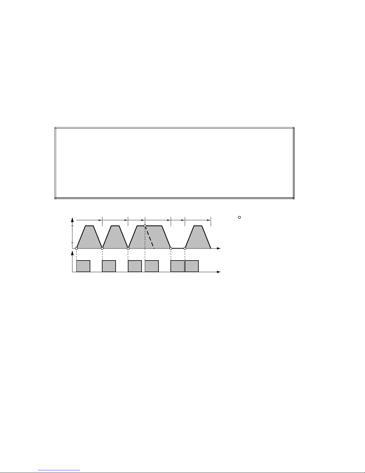
04.97 Programming of Traversing Blocks
4.11.6 M-functions
The M-functions are optional parts of a traversing block. In connection with the moment of
output of the M-function, different block transitions take place.
4.11.6.1 Output of M-functions during positioning
Output of M-functions and traversing movement take place when the execution of the
traversing block is enabled.
Programming:
N10 G01 X100.000 F4000.00 M1=9
N20 X200.000 M1=10
N30 G77 X300.000 FX4000.00 M1=11
N40 X400.000 M1=12
N50 M1=13
N60 X500.000 M1=14
V
x
4000
1000
N10 N20 N30 N40
M
N50
N60
Moment of execution
enable for the next
traversing block
t
M9 M10 M11 M12 M13 M14
t
N10: The M-function M9 is output upon start of the axis.
N20: As the interpolation G01 is active, the block change N10 ➯ N20 takes place at
"digital 0". Therefore, M10 is output at "digital 0".
N30: A transition of the coupling type "interpolation G01 to chaining G77" takes place.
Therefore, M11 is also output at "digital 0".
N40: The block transition N30 ➯ N40 is flying, i.e. the block change and, consequently,
the output of M12 take place in the theoretical braking point.
N50: As only one M-function has been programmed in block N50, M13 is output at "digital
0" of block N40.
N60: At the end of the M-output M13, N60 is read in and at the same time M14 is output.
The utilization of G60 (exact stop) or G66/G67 (loop-over window 1/2) influences the execution
enable of the traversing block and, therefore, the M-output.
©
Siemens AG 1997 All Rights Reserved 6ZB5 440-0VU02
WF 723 C (Programming Guide)
4 – 31
Page 59
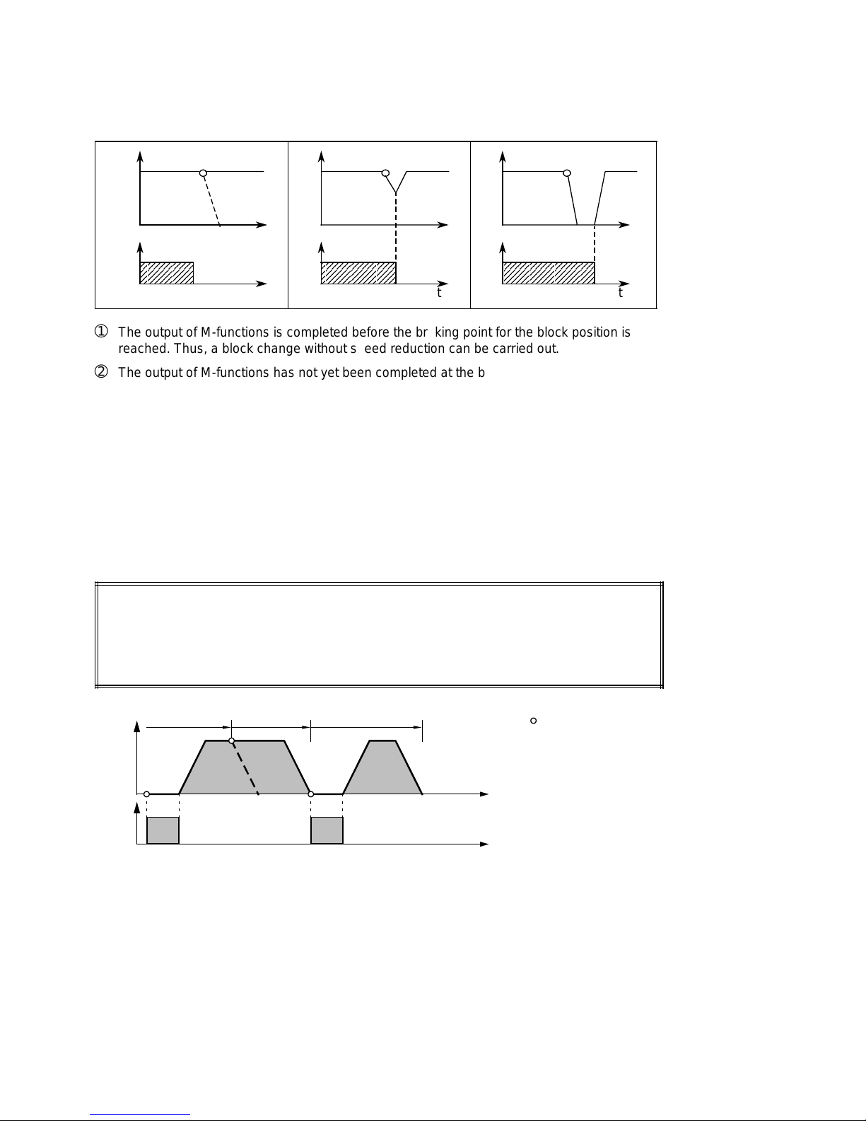
Programming of Traversing Blocks 04.97
aaaaaaaaaaa
a
a
a
a
a
a
aaaaaaaaaaaaaaa
a
a
a
a
a
a
aaaaaaaaaaaaaaaaaaa
a
a
a
a
a
a
Behaviour in case of flying block change:
V
➀
➂➁
t t t
M
aaaaaaaaa
aaaaaaaaa
aaaaaaaaa
t
➀
The output of M-functions is completed before the braking point for the block position is
aaaaaaaaaaaaa
aaaaaaaaaaaaa
aaaaaaaaaaaaa
t
MM
aaaaaaaaaaaaaaaaa
aaaaaaaaaaaaaaaaa
aaaaaaaaaaaaaaaaa
t
reached. Thus, a block change without speed reduction can be carried out.
➁
The output of M-functions has not yet been completed at the braking point. The axis starts
to brake. If the output of M-functions is completed during braking, the block is changed
and the axis begins to accelerate.
➂
The axis comes to a standstill. The next block is not executed before the output of
M-functions is completed.
4.11.6.2 Output of M-functions before positioning
The output of M-functions takes place when the execution of the traversing block is enabled.
The traversing movement takes place after the M-output.
Programming:
N10 G76 X100.000 M1=9
N20 X200.000
N30 X300.000 M1=10
N10 N20 N30
V
x
t
M
M9
M10
t
Moment of execution
enable for the next
traversing block
N10: Upon start, M9 is output, then the traversing movement takes place.
N20: The block change N10 ➯ N20 is flying.
N30: As the type of output is "before positioning", first M10 is output and then the
traversing movement of N30 takes place.
The utilization of G60 (exact stop) or G66/G67 (loop-over window 1/2) influences the execution
enable of the traversing block and, therefore, the M-output.
4 – 32 ©
Siemens AG 1997 All Rights Reserved 6ZB5 440-0VU02
WF 723 C (Programming Guide)
Page 60
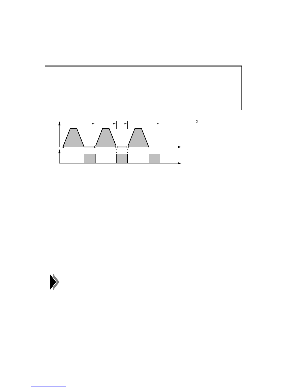
04.97 Programming of Traversing Blocks
4.11.6.3 Output of M-functions after positioning
The traversing movement takes place when the execution of the traversing block is enabled.
The M-output takes place after the traversing movement.
Programming:
N10 G76 X100.000 M1=9
N20 X200.000
N30 M1=10
N40 X300.000 M1=11
N10 N20 N30 N40
V
x
t
M
M9
M10 M11
t
Moment of execution
enable for the next
traversing block
N10: Upon start, the traversing movement takes place. When "digital 0" is reached, M9 is
output. If G60 (exact stop) has been programmed, M9 will only be output when the
PEH window is reached. If G66/G67 (loop-over window 1/2) has been programmed,
the output will be effected in the loop-over window 1/2 when "digital 0" has already
been reached.
N20: Traversing movement only.
N30: As only one M-function has been programmed in block N30, the block change N20 ➯
N30 takes place at "digital 0" of N20.
N40: After the traversing movement, M11 is output.
If several axes have been programmed in the traversing block, the M-function will be output
when all axes have reached "digital 0" or when the PEH window (with G60) or the loop-over
window (with G66/G67) has been reached.
The output or further processing of M-functions in the SIMATIC-S5
controller also influences the cycle time of the S5-program. This can be
avoided by using the fast outputs and programming the M-functions M97
and M98.
©
Siemens AG 1997 All Rights Reserved 6ZB5 440-0VU02
WF 723 C (Programming Guide)
4 – 33
Page 61
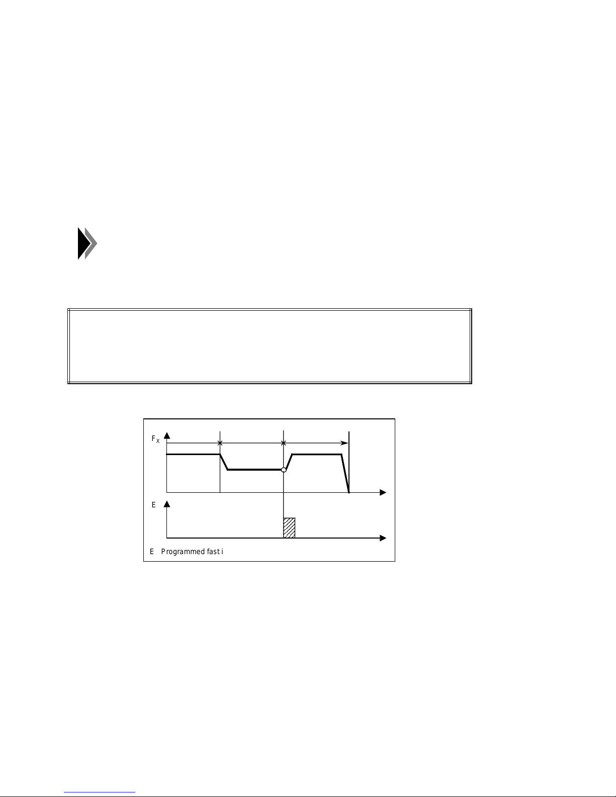
Programming of Traversing Blocks 04.97
aaa
a
a
a
a
a
a
a
a
a
4.11.7 External block change (G50, G51)
With the "External block change" function, a flying block change takes place, triggered by a
fast input. In addition, it is possible to read out the actual value saved at the moment of arrival
of the fast input (flying measured value). The fast input must be programmed with the
"External block change" function.
G50: Absolute dimension for external block change
G51: Incremental dimension for external block change
The G-functions G50 und G51 are only effective block by block and must be newly selected if
required.
The rapid input must be preset in MD 15 of the programmed axis.
Example:
Programming:
N10 G90 G77 X100.000 FX4000.00
N15 G50(G51) X200.000 FX2000.00
N20 G90 X300.000 FX4000.00
Program sequence:
➀
F
X
E
E Programmed fast input
➀
The transition from N10 to N15 is effected on the fly.
➁
The axis traverses until a signal change from 0 to 1 (24 V) takes place at the fast input.
➁
N20N15N10
t
a
a
a
a
a
a
a
a
t
This triggers two reactions:
– Flying block change and, therefore, immediate processing of block N20
– Saving of the current position encoder actual value
By means of the command "read out flying measured value", the saved position
encoder actual value can be read out.
4 – 34 ©
Siemens AG 1997 All Rights Reserved 6ZB5 440-0VU02
WF 723 C (Programming Guide)
Page 62
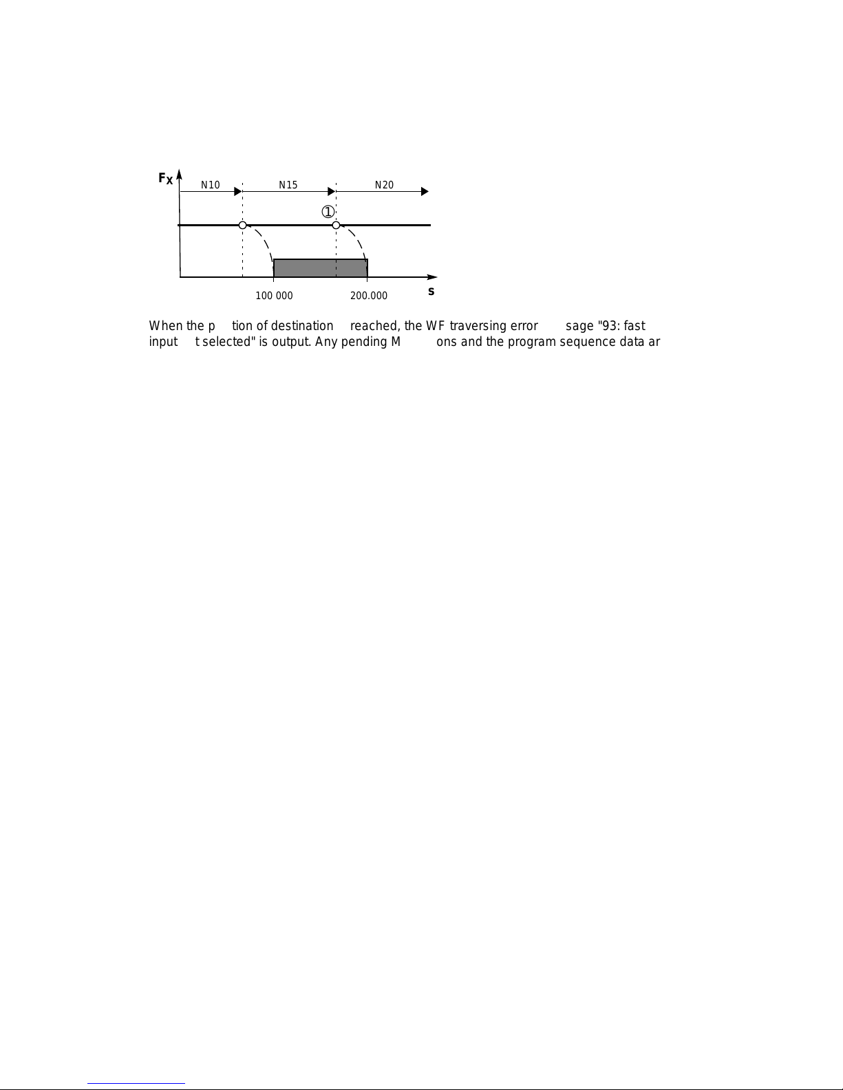
04.97 Programming of Traversing Blocks
aaa
a
a
a
a
a
aaaaa
a
a
a
a
aaaaa
a
a
a
a
aaa
aaa
aaa
aaaaa
a
a
a
a
aaaaa
a
a
a
a
aaaaaaaaa
a
a
a
a
aaaaaaaaa
a
a
a
a
By means of the command "External block change option", you can define the behaviour of
the WF 723 C if the fast input is not selected.
• Option type 0 (error message; basic position)
aaa
F
aaa
X
aaa
aaa
N10
aaa
aaa
N15
➀
a
a
a
a
aaa
aaa
N20
The axis traverses to the corresponding position of destination (G50:
200.000; G51: 300.000). Within the
grey area of the figure, a positive
edge causes a block change at the
"fast input". If the "fast input" is not
➀
selected up to the braking point
,
the axis starts to brake and waits for
aaaaaaa
100.000
aaaaaaa
aaaaaaa
200.000
aaaaaaa
s
the signal change until the
programmed position is reached.
When the position of destination is reached, the WF traversing error message "93: fast
input not selected" is output. Any pending M functions and the program sequence data are
deleted. To continue the program in this case with block number N20, a block search
forwards to N20 must be made after error acknowledgment.
• Option type 1 (flying block cnage)
Even if up to the braking point of N15 the "fast input" was not selected, a flying block
change to block N20 will be effected. The program is continued without interruption.
Special cases:
• The block position in N20 is smaller than the actual position of the position encoder at the
moment of arrival of the fast input:
The axis must stop via the deceleration ramp and then approach the position in opposite
direction.
• G91, and not G90, has been programmed in block N20:
The programmed position in N20 refers to the actual value of the position encoder at the
moment of arrival of the fast input (flying measured value).
• Block N20 only contains M-functions or a dwell time:
The axis is stopped via the brake ramp.
• Block N20 is the program end:
The axis is stopped via the brake ramp.
• Block N15 contains an M-function which has not yet been acknowledged:
The traversing movement is stopped via the brake ramp, but the block changes only after
the M-function has been acknowledged.
Restrictions:
• In a traversing block with G50 or G51, only one axis may be programmed.
• In the block following G50 or G51, too, only one axis may be programmed, and this must
be the same axis.
• To obtain a flying block change (without stop of the axis) when changing from a traversing
block with G50/G51 to the following traversing block, G76 (chaining with quick traverse) or
G77 (chaining with axis velocity) and G64 (maximum loop-over) must be active.
• External block change in synchronism is illegal.
©
Siemens AG 1997 All Rights Reserved 6ZB5 440-0VU02
WF 723 C (Programming Guide)
4 – 35
Page 63
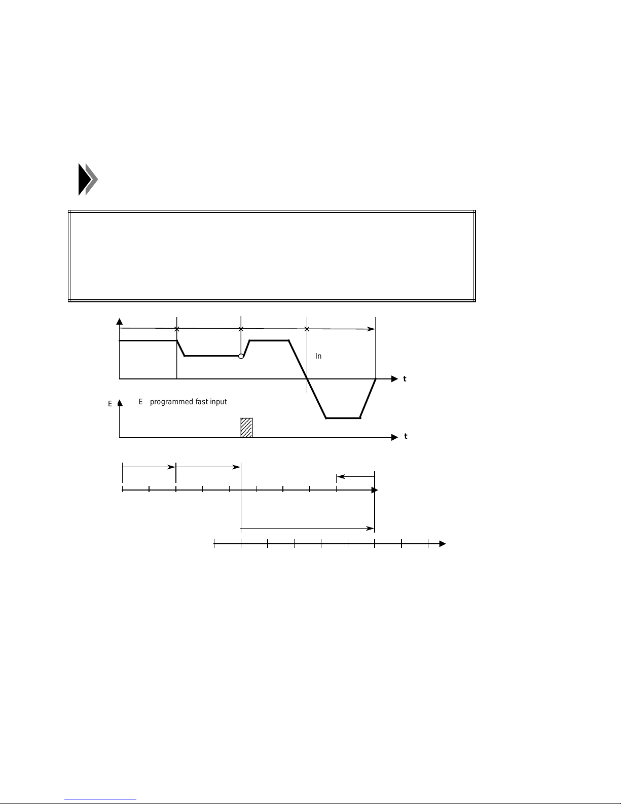
Programming of Traversing Blocks 04.97
aaaaa
a
a
a
a
a
a
a
a
4.11.8 Flying actual-value setting (G87, G88, G89)
The "Flying actual-value setting" function is triggered by a fast input, the block change taking
place on the fly and the actual value being at the same time set to a new measure. In addition,
it is possible to read out the actual value saved at the moment of arrival of the fast input
(command: "Read out flying measured value"). The fast input must be programmed with the
"Flying actual-value setting" function.
The rapid input must be preset in MD 15 of the programmed axis.
Programming:
N10 G90 G77 X100.000 FX4000.00
N15 G89(G88) X50.000 FX2000.00
N20 G90 X300.000 FX4000.00
N25 G87 X400.000 FX4000.00
N10 N15F
X
E
➀
Flying block change from N10 to N15, G89 effecting a movement in positive direction and
E programmed fast input
N10
0 50 100 150 200 250 300 350 400
Measuring system
displaced
➀
N15
E
0 50 100 150 200 250 300 350 400
aaa
aaa
aaa
aaa
N20
➂➁
Inversion of the
direction
N20
N25
N25
x
t
t
Measuring
system
G88, a movement in negative direction, at the programmed velocity of N15.
➁
The axis traverses in the specified direction until a positive edge change takes place at the
fast input. This triggers the following reactions:
– Flying block change and immediate processing of block N20
– Flying actual-value setting to the block position of N15 and, therefore, displacement of
the measuring system
– Saving of the current encoder actual value
The programmed position in block N20 refers to the displaced measuring system.
x
➂
Flying block change from N20 to N25, G87 cancelling the measuring-system displacement
and effecting a reference-measure programming to the block position of N25, as G90 is
still active.
4 – 36 ©
Siemens AG 1997 All Rights Reserved 6ZB5 440-0VU02
WF 723 C (Programming Guide)
Page 64
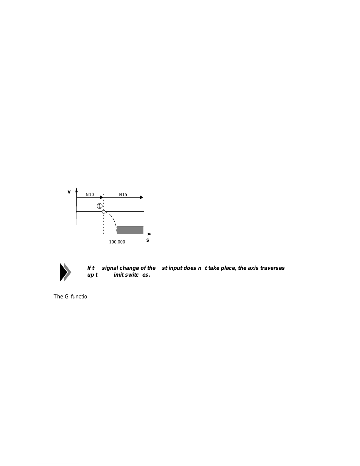
04.97 Programming of Traversing Blocks
aaaaa
a
a
a
a
aaaaa
a
a
a
a
aaa
aaa
aaa
aaa
aaaaaaaaa
a
a
a
a
a
a
a
a
a
a
aaa
a
a
a
a
a
By means of the command "read out flying measuring value", the saved encoder actual value
can be read out.
The measuring-system displacement is maintained until it is deselected by G87 or an
operating-mode change. The existing displacement of the measuring system can be used in
different programs. The measuring system can be displaced anew, without deselecting an
existing measuring-system displacement. If the measuring system was displaced several times
without deselecting the displacement, the values will after deselection of the measuring-system
displacement refer to the original condition of the measuring system.
Special cases:
• The block N20 only contains M-functions or a dwell time:
The axis is stopped via the brake ramp.
• Block N20 is the program end:
The axis is stopped via the brake ramp.
Acquisition range of the fast input:
v
aaa
N10
aaa
➀
a
a
a
a
aaa
N15
aaa
Within the gray area of the figure, a
positive edge causes a flying actualvalue setting. At the moment
➀
(breaking point), a block change
from N10 to N15 takes place. The
release for recognition of the "fast
input" is delayed until the position
aaaaaaa
100.000
aaaaaaa
s
100.000 is reached.
If the signal change of the fast input does not take place, the axis traverses
up to the limit switches.
The G-functions G87, G88 and G89 are only effective block by block and must be newly
selected if required.
Restrictions:
• In a traversing block with G87, G88 or G89, only one axis may be programmed.
• In the block following G88 or G89, too, only one axis may be programmed, and this must
be the same axis.
• To obtain a flying block change (without stop of the axis) when changing from a traversing
block with G88/G89 to the following traversing block, G76 (chaining with quick traverse) or
G77 (chaining with axis velocity) and G64 (maximum loop-over) must be active.
• Flying actual-value setting in synchronism is illegal.
• Flying actual-value setting with roll feed is not possible.
©
Siemens AG 1997 All Rights Reserved 6ZB5 440-0VU02
WF 723 C (Programming Guide)
4 – 37
Page 65
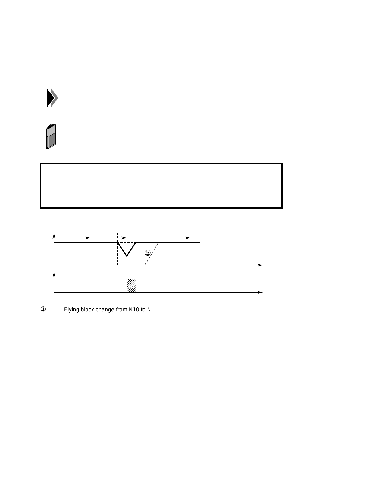
Programming of Traversing Blocks 04.97
aaaaa
a
a
a
a
a
a
a
a
a
a
4.11.9 Program-dependent external read-in enable (G99)
With the "Program-dependent external read-in enable" function, a stop and subsequent
continuation of program execution can be realized through a rapid input. The rapid input must
be programmed with the "Program-dependent external read-in enable" function.
The rapid input for the "Program-dependent external read-in enable"
function must be programmed in the master axis.
The parameterization of the rapid inputs is described in the Description of
Functions, chapter "Rapid inputs/outputs".
Programming:
N10 G90 G77 X100.000 FX4000.00
N15 G99 X200.000
N20 X300.000
①
➁
③
④
➄
➁
Fx
N10
➂➀
N20N15
➃
➄
E
Flying block change from N10 to N15.
In the braking point of N15, the axis starts braking, as G99 inquired the rapid input,
which at that time has not yet been selected.
The rapid input is selected. Program execution changes into block N20, and the axis
accelerates again.
If the rapid input has been selected already in the braking point of N15, a flying block
change will take place.
If the rapid input has not been selected, the axis will be braked to standstill and
remain in position X200.000, indicating PEH. The selection of the rapid input causes
program execution to continue.
aaa
aaa
aaa
aaa
aaa
t
t
4 – 38 ©
Siemens AG 1997 All Rights Reserved 6ZB5 440-0VU02
WF 723 C (Programming Guide)
Page 66
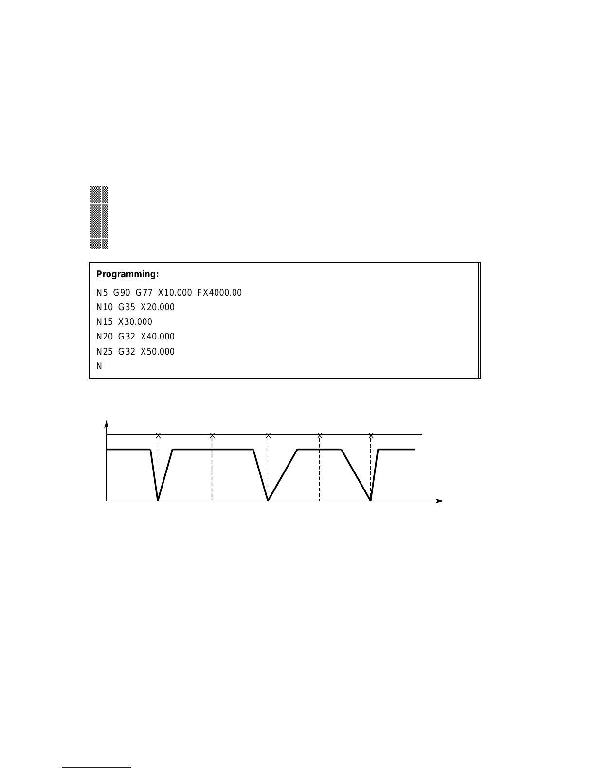
04.97 Programming of Traversing Blocks
aaaaa
a
a
a
a
a
a
a
a
a
a
a
a
a
a
a
a
a
a
a
a
a
a
a
a
a
a
a
a
a
a
a
a
a
4.11.10 Acceleration override G30 to G39
By means of the acceleration override, the acceleration and deceleration behaviour of the
positioning processes can be influenced. The acceleration override is useful if transport
devices are sometimes operated with load and sometimes, without load. Under load, they are
operated with reduced acceleration/deceleration value. The acceleration/deceleration values
are fixed by the machine data MD27 and MD28. By means of G30 to G39, a reduction in
percent of the two values can be obtained in the traversing block. These functions are selfholding.
aaa
a
aaa
a
G-function 2
aaa
a
aaa
a
aaa
a
30 100% acceleration/deceleration override
aaa
a
aaa
a
aaa
a
31 10% acceleration/deceleration override
aaa
a
aaa
a
aaa
a
::
aaa
a
aaa
a
aaa
a
aaa
a
39 90% acceleration/deceleration override
aaa
a
Programming:
N5 G90 G77 X10.000 FX4000.00
N10 G35 X20.000
N15 X30.000
N20 G32 X40.000
N25 G32 X50.000
N30 G30 X60.000
Program sequence:
v
➀
Between N5 and N10, no flying block change takes place, as acceleration and brake
N5
100%
➀
➁ ➂
N10
N15
N20
➃
N25
20%50%50%
➄
N30
100%20%
ramps change. The axis brakes until the PEH exact stop window is reached and then
accelerates with the new acceleration value.
➁
A flying block change from N10 to N15 takes place, as the acceleration override does not
change.
➂
The change of the acceleration override prevents the flying block change.
➃
A flying block change takes place, as the acceleration override does not change.
➄
The change of the acceleration override prevents the flying block change.
The acceleration override is also deselected by:
• Operating-mode change
• Reset of the axis by the control signal [RST]
t
©
Siemens AG 1997 All Rights Reserved 6ZB5 440-0VU02
WF 723 C (Programming Guide)
4 – 39
Page 67

Programming of Traversing Blocks 04.97
4 – 40 ©
Siemens AG 1997 All Rights Reserved 6ZB5 440-0VU02
WF 723 C (Programming Guide)
Page 68

04.97 M-functions with Special Function
5 M-functions with Special Function
5.1 Stop at block end M00
If the M-number 0 is programmed as the 1st M-function in a traversing block, the movement is
stopped at the end of the block when executing the traversing block. The movement is not
continued before another STOP ➯ START edge is triggered.
5.2 Continuous loop M18
If the M-function M18 is programmed as 1st M-function in the last traversing block of a
traversing program, there will be an automatic return to the program start (continuous
processing of a traversing program).
There are two different cases:
• The M-function M18 is output like any other M-function. There will be no return to the
program start before the block N50 (including M18) has completely been executed.
Programming:
N5 G91 X10.000 F100.00
...................
N50 G91 X50.000 F100.00 M1=18
• If the M-function M18 is programmed as the last block of a traversing program, the
M-function will not be output, but the axis will immediately return to the program start.
Programming:
N5 G91 X10.000 F100.00
...................
N50 G91 X50.000 F100.00
N55 M1=18
In this example, the WF 723 C executes a flying block change to the program start, without
any velocity reduction in the X-axis.
©
Siemens AG 1997 All Rights Reserved 6ZB5 440-0VU02
WF 723 C (Programming Guide)
5 – 1
Page 69

M-functions with Special Function 04.97
5.3 Subroutine end M17/M29
If the M-function M17 or M29 is programmed as the 1st M-function is a subroutine, a return
follows into the superior program level when executing the program.
M17 or M29 must only be programmed if the program end shall take place prematurely.
5.4 Program end M02/M30
M02 and M30 terminate an NC program. The M-function M02 or M30 must be programmed in
a separate block. At the end of the program all G-functions are brought into basic position.
M02 or M30 must only be programmed if the program end shall take place prematurely.
5 – 2 ©
Siemens AG 1997 All Rights Reserved 6ZB5 440-0VU02
WF 723 C (Programming Guide)
Page 70

04.97 Tool Offsets
6 Tool Offsets
6.1 Tool offset G43, G44
With the tool offset, an existing machining program can still be used, even after the tool
dimensions have changed. Normally, the programming refers to the tool zero point. Through
tool wear or exchange of the tool, the position of the tool tip may change. This change can be
compensated through the tool offset, without requiring any changes in the machining program.
Programming:
N5 G90 (G43) (G44) G01 X50.000 F4000.00 D5 ➯ Selection
N10 X80.000
N15 X150.000 D6 ➯ New selection
N20 X200.000
N25 X300.000 D0 ➯ Deselection
N5: The tool offset is selected by means of the D-number D5. With the optional
indications G43 or G44, the direction of action of the tool offset can be fixed. As G43
is active in basic position, G43 need only be entered to deselect an active G44. The
axis positions on X50.000, taking into account the tool offset memory D5.
N10: The tool offset D5 remains active.
N15: Through new selection of D6, D5 is deselected. The axis positions on X150.000,
taking into account the tool offset memory D6.
N20: The tool offset D6 remains active.
N25: Through deselection of the tool offset by means of D0, D6 becomes inactive. The
axis positions on X300.000, without tool offset.
A selected tool offset is deselected by:
• New selection of another D-number
• Deselection through D0
• Program end or through M30 or M02
• Operating-mode change
• Program abortion through a WF traversing error message
• Block search forwards, as the program is newly decoded
• The control signal "reset axis" [RST]
• Switch-on of the follow-up mode [NFB]
A selected tool offset is maintained in:
• Jumps into subroutines or returns to the main program
• Program continuous loops through M18 or G04 (dwell time in the last traversing block)
The calculation of the tool offset is only taken into account in absolutedimension programming (G90).
©
Siemens AG 1997 All Rights Reserved 6ZB5 440-0VU02
WF 723 C (Programming Guide)
6 – 1
Page 71
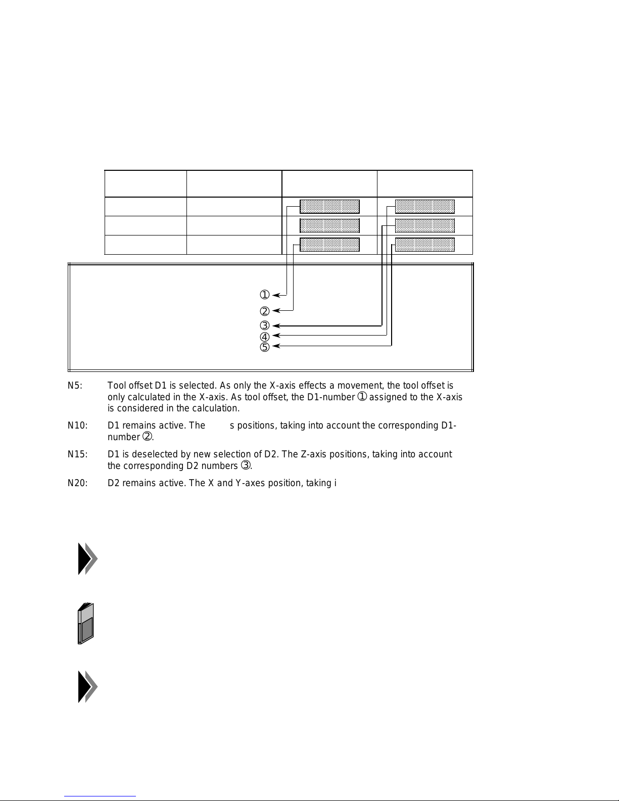
Tool Offsets 04.97
aaaaaaaaaaaaaaaaa
a
a
a
a
a
a
aaaaaaaaaaaaaaaaa
a
a
a
a
aaaaaaaaaaaaaaaaa
a
a
a
a
a
a
aaaaaaaaaaaaaaaaa
a
a
a
a
a
a
aaaaaaaaaaaaaaaaa
a
a
a
a
aaaaaaaaaaaaaaaaa
a
a
a
a
a
a
6.2 Tool offset memory
A total of 20 tool offset memories per axis are available. They are called with D1 to D20. The
tool offset memories are firmly assigned to the hardware axes A*, B* and C*. The definition of
the axis assignment (MD38) determines the assignment of the axis names (X, Y, Z, A, B, and
C). In the traversing program, the respective tool offset memory is addressed via the assigned
axis names.
Hardware axis Axis name (MD 38) Tool offset
D1
aaaaaaaaaaaaaaa
A* X Value Value
B* Z Value Value
C* Y Value Value
aaaaaaaaaaaaaaa
aaaaaaaaaaaaaaa
aaaaaaaaaaaaaaa
aaaaaaaaaaaaaaa
aaaaaaaaaaaaaaa
aaaaaaaaaaaaaaa
aaaaaaaaaaaaaaa
Tool offset
D2
aaaaaaaaaaaaaaa
aaaaaaaaaaaaaaa
aaaaaaaaaaaaaaa
aaaaaaaaaaaaaaa
aaaaaaaaaaaaaaa
aaaaaaaaaaaaaaa
aaaaaaaaaaaaaaa
aaaaaaaaaaaaaaa
Programming:
N5 G77 X100.000 FX2000.00 D1
N10 Y100.000 FY2000.00
N15 Z100.000 FZ2000.00 D2
N20 X200.000 Y200.000
➀
➁
➂
➃
➄
N25 X300.000 Y300.000 Z300.000 D0
N5: Tool offset D1 is selected. As only the X-axis effects a movement, the tool offset is
only calculated in the X-axis. As tool offset, the D1-number
➀
assigned to the X-axis
is considered in the calculation.
N10: D1 remains active. The Y-axis positions, taking into account the corresponding D1-
➁
number
.
N15: D1 is deselected by new selection of D2. The Z-axis positions, taking into account
the corresponding D2 numbers
➂
.
N20: D2 remains active. The X and Y-axes position, taking into account the corresponding
➃ ➄
D2-numbers
.
N25: The tool offset is deselected by means of D0 in the programmed axes X, Y and Z.
If a tool offset shall not be taken into account in all programmed axes, "0"
must be entered in the respective tool offset memories (basic position).
The input/output of tool offsets is described in the Planning Guide
"Command identifiers for SIMATIC S5 or S7" under AK14.
As in synchronism, the movement of the slave axis is always derived from
the master axis, the tool offset is taken into account in the calculation in
the master axis only.
6 – 2 ©
Siemens AG 1997 All Rights Reserved 6ZB5 440-0VU02
WF 723 C (Programming Guide)
Page 72
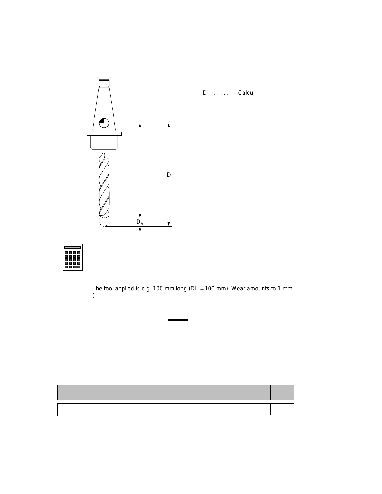
04.97 Tool Offsets
aaaaa
a
a
a
a
aaaaaaaaaaaaaaaaa
a
a
a
a
a
Abbreviation
Designation
Lower limit Upper limit
Unit
6.3 Variants of the tool offset
The tool offset is composed of tool length offset and tool length wear.
D . . . . . Calculated tool length
. . . . . Effective tool length
D
L
D
. . . . Wear
V
D
D
L
aaa
D
aaa
V
aaaaaaaaaaaaaaa
D = DL + D
aaaaaaaaaaaaaaa
a
a
V
Example: The tool applied is e.g. 100 mm long (DL = 100 mm). Wear amounts to 1 mm
(DV = –1 mm).
Therefore, the active tool offset is
D = D
+ DV = (100) + (–1) = 99 mm.
L
6.3.1 Tool length offset
The tool length offset is the actual tool length from the tool zero point to the tool tip.
P2 Tool length offset 1 – 9 999.999 + 9 999.999
©
Siemens AG 1997 All Rights Reserved 6ZB5 440-0VU02
WF 723 C (Programming Guide)
mm
6 – 3
Page 73
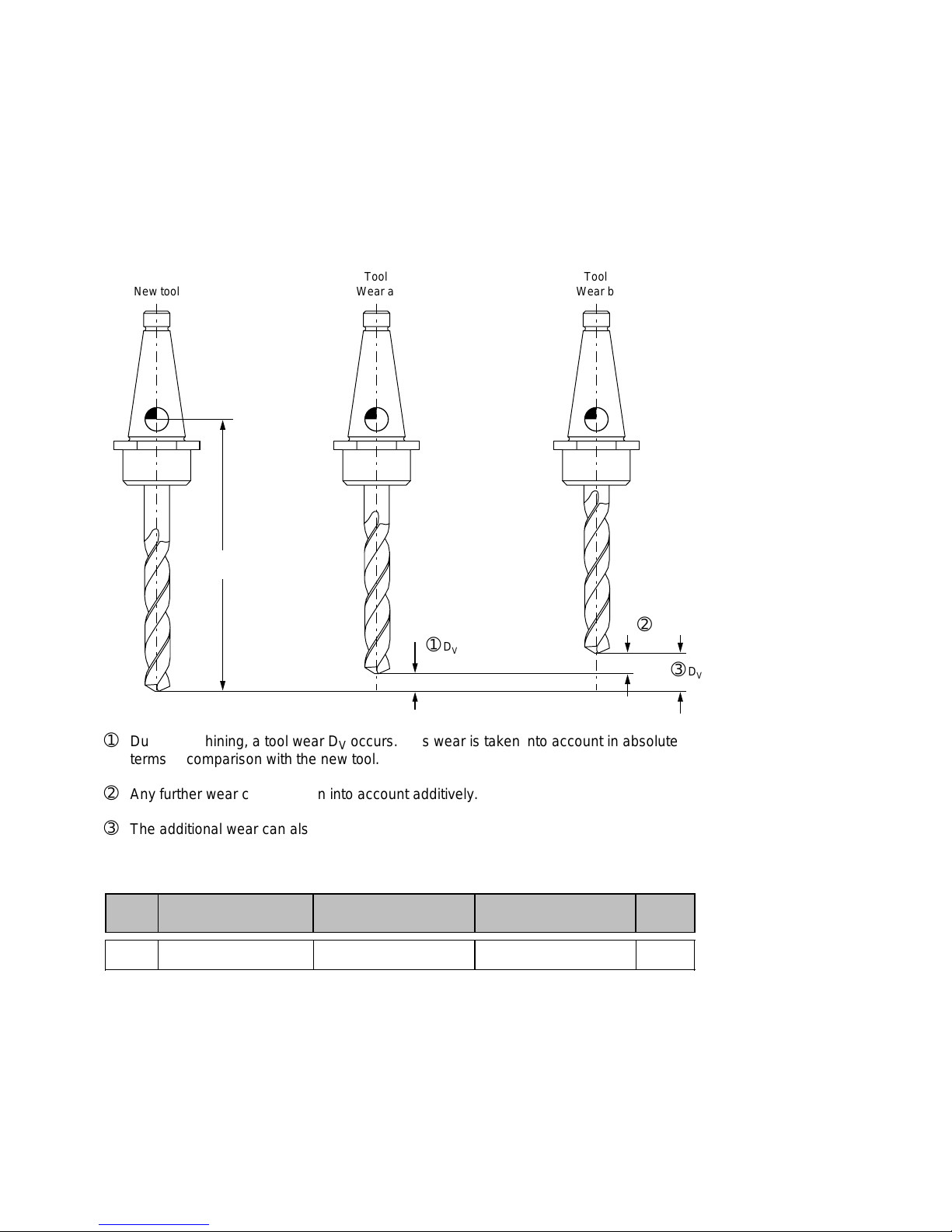
Tool Offsets 04.97
aaaaaaaaa
a
a
a
a
a
aaaaa
a
a
a
a
a
a
a
aaa
a
a
a
a
a
aaaaaaa
a
a
a
a
aaaaaaa
a
a
a
a
a
a
a
a
a
aaaaaaaaa
a
a
a
a
a
a
a
a
6.3.2 Tool length wear
By means of the tool length wear, a change of the tool length due to wear can be
compensated in two ways:
Absolute: Defining a fixed value of wear
Additive: Adding an offset value to the actual contents of the tool length wear.
aaaaa
aaaaaaa
New tool
aaaaaaa
a
Tool
aaaaa
a
a
aaaaa
Wear a
aaaaa
a
a
a
aaaaaaa
Tool
aaaaaaa
aaaaaaa
Wear b
aaaaaaa
D
L
aaa
a
aaa
a
➀
D
V
aaa
a
➀
During machining, a tool wear DV occurs. This wear is taken into account in absolute
terms in comparison with the new tool.
➁
Any further wear can be taken into account additively.
➂
The additional wear can also be considered absolutely.
Abbre-
viation
Designation
Lower limit Upper limit
P5 Tool length wear 1 – 2, 000 + 2, 000
➁
a
a
a
a
aaaaa
➂
D
aaaaa
V
Unit
mm
6 – 4 ©
Siemens AG 1997 All Rights Reserved 6ZB5 440-0VU02
WF 723 C (Programming Guide)
Page 74

04.97 Tool Offsets
6.4 Direction of tool offset
• Negative tool offset G44
Usually, the tool faces the workpiece in negative direction. The position value is reduced
by traversing. With G44, the position value is corrected as follows:
X
= X
ms
X
: Position of measuring system
ms
X
Soll
D: Tool offset
• Positve tool offset G43
The tool may, however, also faces the workpiece in positive direction. The position value is
increased by traversing. With G43, the position value is corrected as follows:
X
= X
ms
+ (D)
Soll
: Programmed set position
– (D)
Soll
In order to program a tool offset in the traversing block, at least the tool
length offset must be entered. If no
offset is to be calculated although it
was selected before, tool length offset and tool length wear must be
defined as 0. A tool length wear is deleted by the absolute input of 0.
©
Siemens AG 1997 All Rights Reserved 6ZB5 440-0VU02
WF 723 C (Programming Guide)
6 – 5
Page 75

Tool Offsets 04.97
6 – 6 ©
Siemens AG 1997 All Rights Reserved 6ZB5 440-0VU02
WF 723 C (Programming Guide)
Page 76
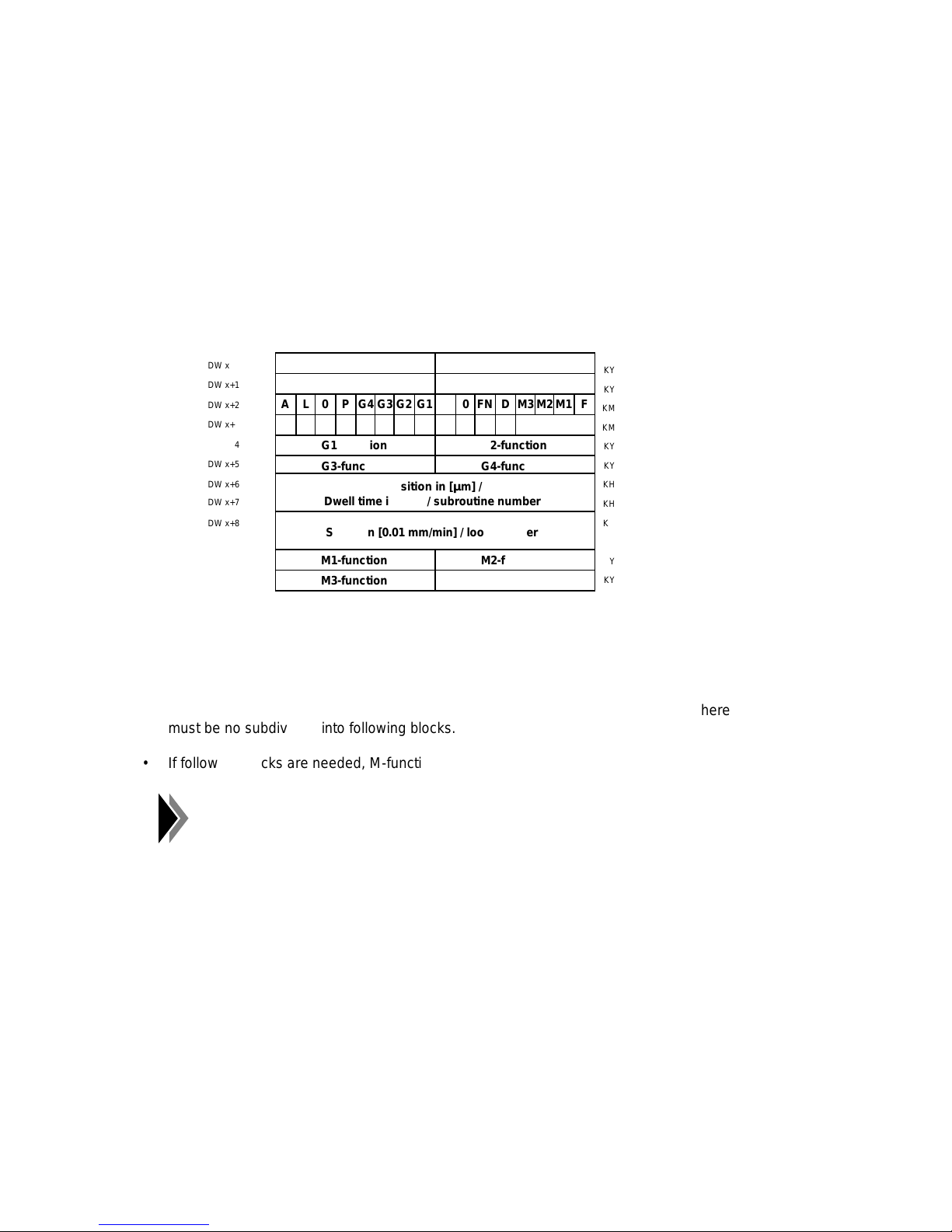
04.97 Programming in S5 Format
aaaaaaa
a
a
aaaaaaa
a
a
a
a
aaaaa
a
a
a
a
aaaaaaa
a
a
aaaaaaa
a
a
a
a
aaaaaaa
a
a
a
a
aaaaaaa
a
a
aaaaaaa
a
a
aaaaaaa
a
a
a
a
aaaaaaa
a
a
aaaaaaa
a
a
a
a
a
aaaaaaa
a
a
a
7 Programming in S5 Format
This chapter is only relevant for you if you manage traversing programs directly in S5 data
blocks. The examples in all other chapters are programmed in DIN format, which is used by
COM 723. Here, you will learn how to program these examples in S5 format.
Block format in the S5 format
aaa
DW x
aaa
aaaaa
DW x+1
aaaaa
aaaaa
DW x+2
aaaaa
DW x+3
aaaaa
aaaaa
DW x+4
aaaaa
DW x+5
aaaaa
aaaaa
DW x+6
aaaaa
DW x+7
aaaaa
DW x+8
aaaaa
aaaaa
DW x+9
aaaaa
aaaaa
DW x+10
aaaaa
DW x+11
Internally assigned
A
L 0 P G4 G3 G2 G1
G1-function
G3-function
Position in [µm] /
Dwell time in [ms] / subroutine number
Speed in [0.01 mm/min] / loop number
a
a
a
M1-function
M3-function
Continue identifierProgram number
Block number
0
0 FN D M3 M2 M1 F
Axis no.X Y Z A B C 0 0 0 0 0 0
G2-function
G4-function
M2-function
D-function
KY
KY
KM
KM
KY
KY
KH
KH
KH
KH
KY
KY
General guidelines for the conversion DIN format ➯ S5 format
• If all data of a traversing block have to be accommodated in a block in S5 format, there
must be no subdivision into following blocks.
• If following blocks are needed, M-function and D-number must be stored in the main block.
15 0
The program number is not contained in the table because it does not
change within a program. In S5 format, the program number must be
entered in the corresponding place.
©
Siemens AG 1997 All Rights Reserved 6ZB5 440-0VU02
WF 723 C (Programming Guide)
7 – 1
Page 77
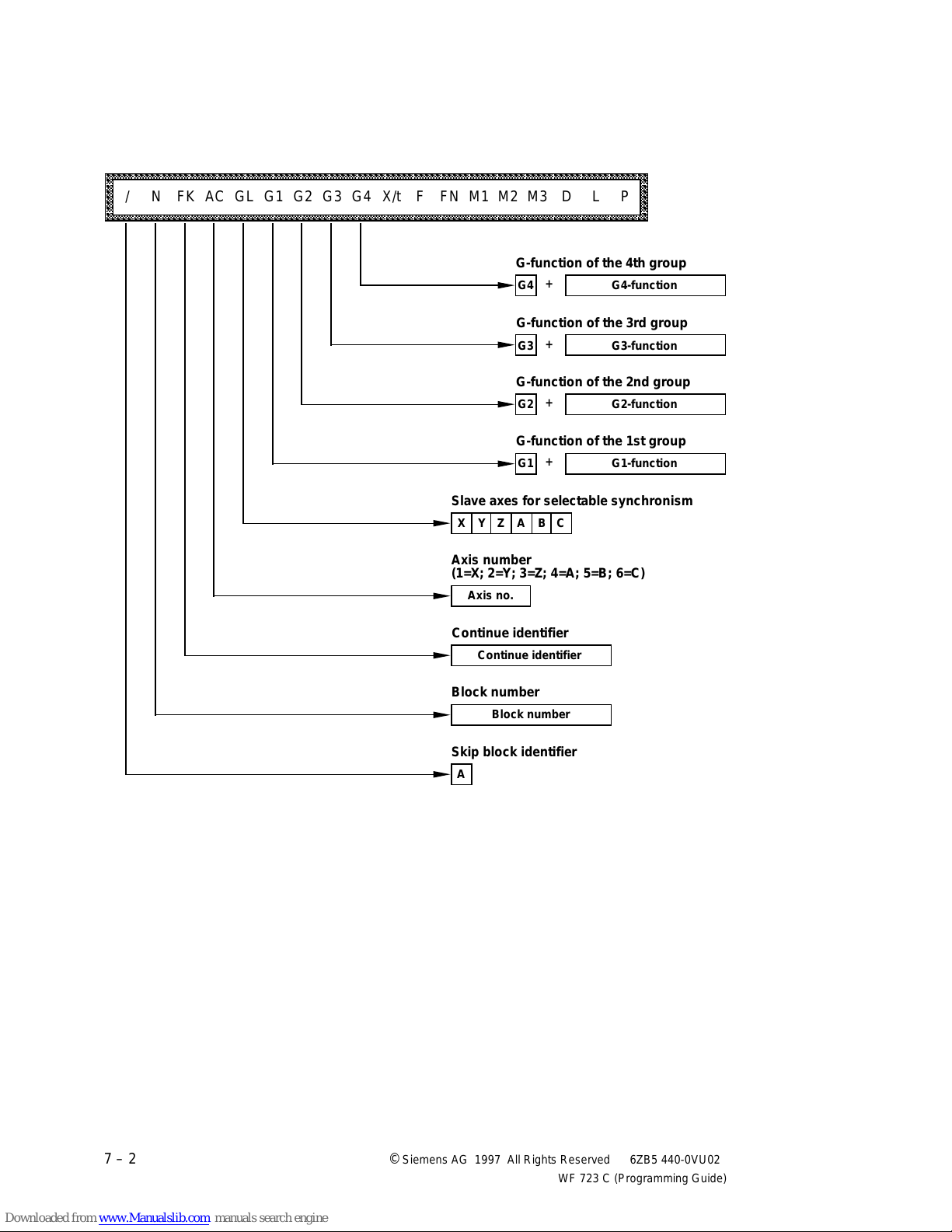
Programming in S5 Format 04.97
aaaaaaaaaaaaaaaaaaaaaaaaaaaaaaaaaaaaaaaaaaaaaaaaaaaaaaaaaaaaaaaaaaaaaaaaaaaaaaaaaaaaaaaaaaaaaaaaa
a
a
a
a
a
a
a
a
a
a
a
a
a
a
a
a
a
aaa
aaa
aaa
aaa
aaa
aaa
aaa
aaa
aaa
The following is a simple tabular representation, the columns including the block information
and the lines showing the blocks.
aaaaaaaaaaaaaaaaaaaaaaaaaaaaaaaaaaaaaaaaaaaaaaaaaaaaaaaaaaaaaaaaaaaaaaaaaaaaaaaaaaaaaaaaaaaaaaa
aaaaaaaaaaaaaaaaaaaaaaaaaaaaaaaaaaaaaaaaaaaaaaaaaaaaaaaaaaaaaaaaaaaaaaaaaaaaaaaaaaaaaaaaaaaaaaa
aaaaaaaaaaaaaaaaaaaaaaaaaaaaaaaaaaaaaaaaaaaaaaaaaaaaaaaaaaaaaaaaaaaaaaaaaaaaaaaaaaaaaaaaaaaaaaa
aaaaaaaaaaaaaaaaaaaaaaaaaaaaaaaaaaaaaaaaaaaaaaaaaaaaaaaaaaaaaaaaaaaaaaaaaaaaaaaaaaaaaaaaaaaaaaa
aaaaaaaaaaaaaaaaaaaaaaaaaaaaaaaaaaaaaaaaaaaaaaaaaaaaaaaaaaaaaaaaaaaaaaaaaaaaaaaaaaaaaaaaaaaaaaa
/ N FK AC GL G1 G2 G3 G4 X/t F FN M1 M2 M3 D L P
aaaaaaaaaaaaaaaaaaaaaaaaaaaaaaaaaaaaaaaaaaaaaaaaaaaaaaaaaaaaaaaaaaaaaaaaaaaaaaaaaaaaaaaaaaaaaaa
aaaaaaaaaaaaaaaaaaaaaaaaaaaaaaaaaaaaaaaaaaaaaaaaaaaaaaaaaaaaaaaaaaaaaaaaaaaaaaaaaaaaaaaaaaaaaaa
aaaaaaaaaaaaaaaaaaaaaaaaaaaaaaaaaaaaaaaaaaaaaaaaaaaaaaaaaaaaaaaaaaaaaaaaaaaaaaaaaaaaaaaaaaaaaaa
G-function of the 4th group
+
G4 G4-function
G-function of the 3rd group
+
G3 G3-function
G-function of the 2nd group
+
G2 G2-function
G-function of the 1st group
+
G1 G1-function
Slave axes for selectable synchronism
X Y Z A B C
Axis number
(1=X; 2=Y; 3=Z; 4=A; 5=B; 6=C)
Axis no.
a
a
a
a
a
a
a
a
Continue identifier
Continue identifier
Block number
Block number
Skip block identifier
A
7 – 2 ©
Siemens AG 1997 All Rights Reserved 6ZB5 440-0VU02
WF 723 C (Programming Guide)
Page 78
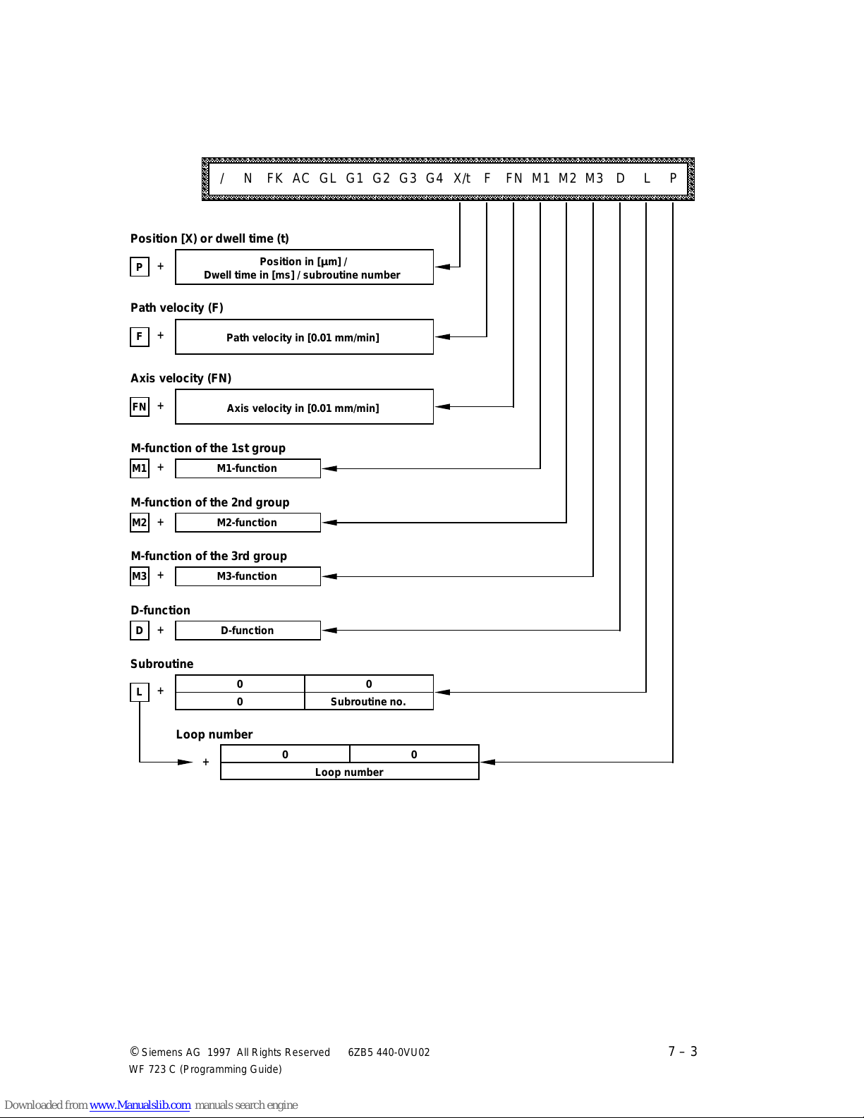
04.97 Programming in S5 Format
aaaaaaaaaaaaaaaaaaaaaaaaaaaaaaaaaaaaaaaaaaaaaaaaaaaaaaaaaaaaaaaaaaaaaaaaaaaaaaaaaaaaaaaaaaaaaaaaa
a
a
a
a
a
a
a
a
a
a
a
a
a
a
a
a
a
aaa
a
a
a
aaa
a
a
a
aaa
a
a
a
aaa
a
a
a
aaa
a
a
a
aaa
a
a
a
aaa
a
a
a
aaa
a
a
a
aaa
aaa
aaaaaaaaaaaaaaaaaaaaaaaaaaaaaaaaaaaaaaaaaaaaaaaaaaaaaaaaaaaaaaaaaaaaaaaaaaaaaaaaaaaaaaaaaaaaaaa
aaaaaaaaaaaaaaaaaaaaaaaaaaaaaaaaaaaaaaaaaaaaaaaaaaaaaaaaaaaaaaaaaaaaaaaaaaaaaaaaaaaaaaaaaaaaaaa
aaaaaaaaaaaaaaaaaaaaaaaaaaaaaaaaaaaaaaaaaaaaaaaaaaaaaaaaaaaaaaaaaaaaaaaaaaaaaaaaaaaaaaaaaaaaaaa
aaaaaaaaaaaaaaaaaaaaaaaaaaaaaaaaaaaaaaaaaaaaaaaaaaaaaaaaaaaaaaaaaaaaaaaaaaaaaaaaaaaaaaaaaaaaaaa
aaaaaaaaaaaaaaaaaaaaaaaaaaaaaaaaaaaaaaaaaaaaaaaaaaaaaaaaaaaaaaaaaaaaaaaaaaaaaaaaaaaaaaaaaaaaaaa
/ N FK AC GL G1 G2 G3 G4 X/t F FN M1 M2 M3 D L P
aaaaaaaaaaaaaaaaaaaaaaaaaaaaaaaaaaaaaaaaaaaaaaaaaaaaaaaaaaaaaaaaaaaaaaaaaaaaaaaaaaaaaaaaaaaaaaa
aaaaaaaaaaaaaaaaaaaaaaaaaaaaaaaaaaaaaaaaaaaaaaaaaaaaaaaaaaaaaaaaaaaaaaaaaaaaaaaaaaaaaaaaaaaaaaa
aaaaaaaaaaaaaaaaaaaaaaaaaaaaaaaaaaaaaaaaaaaaaaaaaaaaaaaaaaaaaaaaaaaaaaaaaaaaaaaaaaaaaaaaaaaaaaa
Position [X) or dwell time (t)
a
a
+
P
Dwell time in [ms] / subroutine number
Position in [µm] /
Path velocity (F)
+
F
a
a
Path velocity in [0.01 mm/min]
Axis velocity (FN)
+
FN
a
a
Axis velocity in [0.01 mm/min]
M-function of the 1st group
+
M1
a
a
M1-function
M-function of the 2nd group
a
a
+
M2
M2-function
M-function of the 3rd group
+
a
a
M3
M3-function
a
a
a
a
a
a
a
a
D-function
+
D
a
a
Subroutine
+
a
a
L
Loop number
D-function
0 0
0 Subroutine no.
+
0 0
Loop number
©
Siemens AG 1997 All Rights Reserved 6ZB5 440-0VU02
WF 723 C (Programming Guide)
7 – 3
Page 79
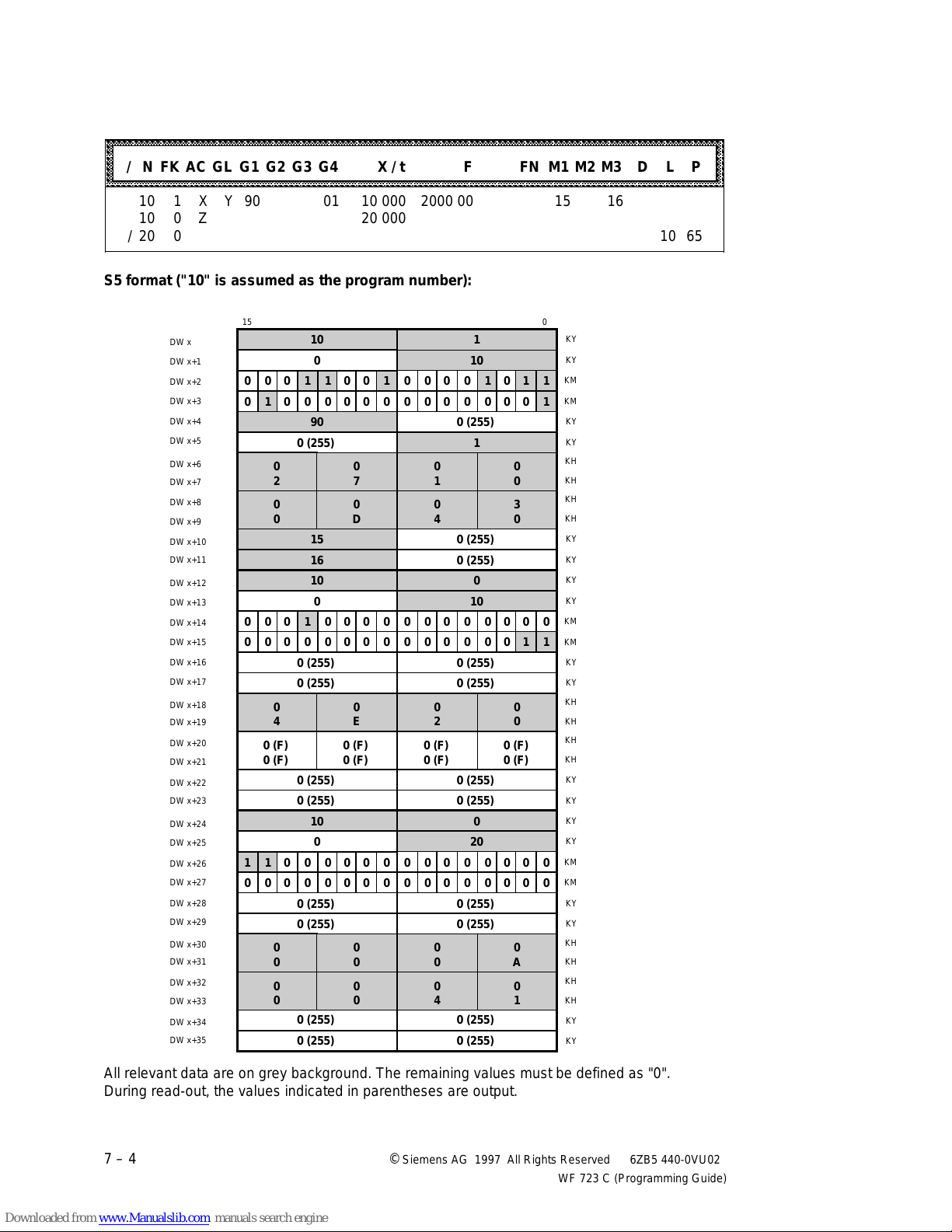
Programming in S5 Format 04.97
aaaaaaaaaaaaaaaaaaaaaaaaaaaaaaaaaaaaaaaaaaaaaaaaaaaaaaaaaaaaaaaaaaaaaaaaaaaaaaaaaaaaaaaaaaaaaaaaaaaaaaaaaaaaaaa
a
a
a
a
a
a
a
a
a
a
a
a
a
a
a
a
a
aaaaaaa
a
a
aaaaaaa
a
a
a
a
aaaaa
a
a
a
a
aaaaaaa
a
a
aaaaaaa
a
a
a
a
aaaaaaa
a
a
aaaaaaa
a
a
a
a
aaaaaaa
a
a
a
a
aaaaaaa
a
a
aaaaaaa
a
a
a
a
aaaaaaa
a
a
a
aaaaaaa
a
a
a
a
a
aaaaaaa
a
a
a
aaaaaaa
a
a
a
a
a
aaaaaaa
a
a
a
a
a
aaaaaaa
a
a
a
aaaaaaa
a
a
a
a
a
aaaaaaa
a
a
a
aaaaaaa
a
aaaaaaa
a
aaaaaaa
a
aaaaaaa
a
a
a
a
a
aaaaaaa
a
a
a
aaaaaaa
a
a
a
a
a
aaaaaaa
a
a
a
aaaaaaa
a
aaaaaaa
a
aaaaaaa
a
aaaaaaa
a
a
a
aaaaaaa
a
a
a
a
a
aaaaaaa
a
a
a
a
a
aaaaaaa
a
a
a
aaaaaaa
a
a
a
a
a
aaaaaaa
a
a
a
aaaaaaa
a
a
a
aaaaaaa
a
a
a
aaaaaaa
a
a
a
aaaaaaa
a
aaaaaaa
a
aaaaaaa
a
aaaaaaa
a
a
a
aaaaaaa
a
a
a
Example of conversion table ➯ data words
aaaaaaaaaaaaaaaaaaaaaaaaaaaaaaaaaaaaaaaaaaaaaaaaaaaaaaaaaaaaaaaaaaaaaaaaaaaaaaaaaaaaaaaaaaaaaaaaaaaaaaaaaaaaa
aaaaaaaaaaaaaaaaaaaaaaaaaaaaaaaaaaaaaaaaaaaaaaaaaaaaaaaaaaaaaaaaaaaaaaaaaaaaaaaaaaaaaaaaaaaaaaaaaaaaaaaaaaaaa
aaaaaaaaaaaaaaaaaaaaaaaaaaaaaaaaaaaaaaaaaaaaaaaaaaaaaaaaaaaaaaaaaaaaaaaaaaaaaaaaaaaaaaaaaaaaaaaaaaaaaaaaaaaaa
aaaaaaaaaaaaaaaaaaaaaaaaaaaaaaaaaaaaaaaaaaaaaaaaaaaaaaaaaaaaaaaaaaaaaaaaaaaaaaaaaaaaaaaaaaaaaaaaaaaaaaaaaaaaa
aaaaaaaaaaaaaaaaaaaaaaaaaaaaaaaaaaaaaaaaaaaaaaaaaaaaaaaaaaaaaaaaaaaaaaaaaaaaaaaaaaaaaaaaaaaaaaaaaaaaaaaaaaaaa
/ N FK AC GL G1 G2 G3 G4 X / t F FN M1 M2 M3 D L P
aaaaaaaaaaaaaaaaaaaaaaaaaaaaaaaaaaaaaaaaaaaaaaaaaaaaaaaaaaaaaaaaaaaaaaaaaaaaaaaaaaaaaaaaaaaaaaaaaaaaaaaaaaaaa
aaaaaaaaaaaaaaaaaaaaaaaaaaaaaaaaaaaaaaaaaaaaaaaaaaaaaaaaaaaaaaaaaaaaaaaaaaaaaaaaaaaaaaaaaaaaaaaaaaaaaaaaaaaaa
aaaaaaaaaaaaaaaaaaaaaaaaaaaaaaaaaaaaaaaaaaaaaaaaaaaaaaaaaaaaaaaaaaaaaaaaaaaaaaaaaaaaaaaaaaaaaaaaaaaaaaaaaaaaa
10 1 X Y 90 01 10 000 2000 00 15 16
10 0 Z 20 000
/20 0 10 65
S5 format ("10" is assumed as the program number):
15 0
aaa
DW x
aaa
aaaaa
DW x+1
aaaaa
DW x+2
aaaaa
aaaaa
DW x+3
aaaaa
DW x+4
aaaaa
aaaaa
DW x+5
aaaaa
DW x+6
aaaaa
aaaaa
DW x+7
aaaaa
aaaaa
DW x+8
aaaaa
DW x+9
aaaaa
aaaaa
DW x+10
aaaaa
DW x+11
aaaaa
aaaaa
DW x+12
aaaaa
aaaaa
DW x+13
aaaaa
DW x+14
aaaaa
aaaaa
DW x+15
aaaaa
DW x+16
aaaaa
aaaaa
DW x+17
DW x+18
aaaaa
DW x+19
aaaaa
aaaaa
DW x+20
aaaaa
DW x+21
aaaaa
aaaaa
DW x+22
DW x+23
aaaaa
DW x+24
aaaaa
aaaaa
DW x+25
aaaaa
DW x+26
aaaaa
aaaaa
DW x+27
aaaaa
DW x+28
aaaaa
aaaaa
DW x+29
aaaaa
DW x+30
aaaaa
DW x+31
aaaaa
DW x+32
DW x+33
aaaaa
DW x+34
aaaaa
DW x+35
10 1
0 10
0
0 0 1 1 0 0 1
0
0 0 0 1 0 1 1
0 1 0 0 0 0 0 0 0 0 0 0 0 0 0 1
90
0 (255)
0 (255)
0
2
0
0
a
a
a
a
a
a
a
0
a
a
a
a
a
a
a
a
a
a
a
0 0 1 0 0 0 0
0 0 0 0 0 0 0 0 0 0 0 0 0 0 1 1
0 (255)
0 (255)
0
4
0 (F)
0 (F)
0 (255)
0 (255)
a
a
a
a
1
a
a
a
a
a
a
a
a
1 0 0 0 0 0 0
0 0 0 0 0 0 0 0 0 0 0 0 0 0 0 0
0 (255)
0 (255)
0
0
0
0
a
a
0 (255)
0 (255)
0
7
0
D
15
16
0
1
0
4
0 (255)
0 (255)
10 0
0 10
0
0 0 0 0 0 0 0
0 (255)
0 (255)
0
E
0 (F)
0 (F)
0
2
0 (F)
0 (F)
0 (255)
0 (255)
10 0
0 20
0
0 0 0 0 0 0 0
0 (255)
0 (255)
0
0
0
0
0
0
0
4
0 (255)
0 (255)
1
0
0
3
0
0
0
0 (F)
0 (F)
0
A
0
1
KY
KY
KM
KM
KY
KY
KH
KH
KH
KH
KY
KY
KY
KY
KM
KM
KY
KY
KH
KH
KH
KH
KY
KY
KY
KY
KM
KM
KY
KY
KH
KH
KH
KH
KY
KY
a
a
a
a
a
a
a
a
All relevant data are on grey background. The remaining values must be defined as "0".
During read-out, the values indicated in parentheses are output.
7 – 4 ©
Siemens AG 1997 All Rights Reserved 6ZB5 440-0VU02
WF 723 C (Programming Guide)
Page 80
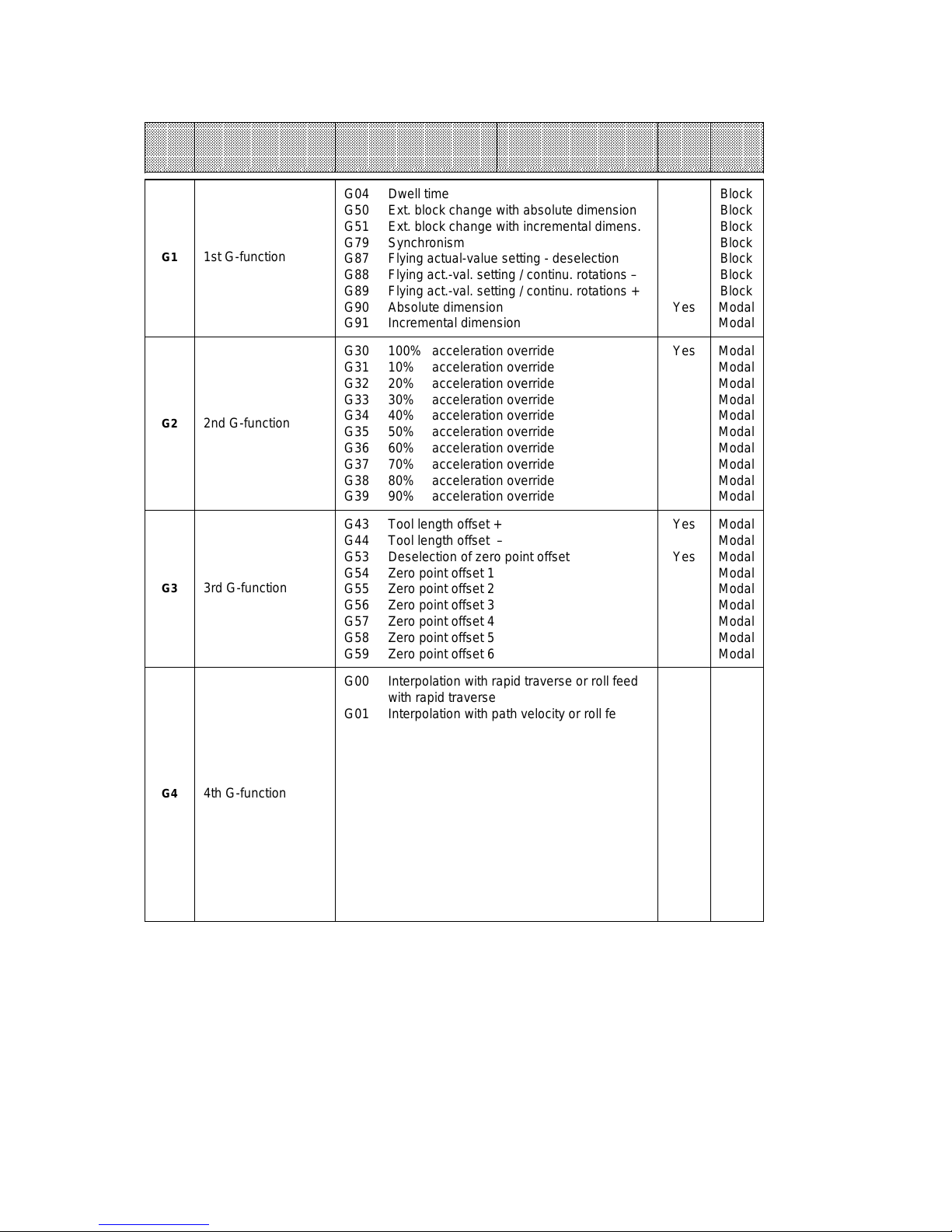
04.97 Programming in S5 Format
aaaaaaaaaaaaaaaaaaaaaaaaaaaaaaaaaaaaaaaaaaaaaaaaaaaaaaaaaaaaaaaaaaaaaaaaaaaaaaaaaaaaaaaaaaaaaaaaaaaaaaaaaaaaaaa
a
a
a
a
a
a
a
a
a
a
a
a
a
a
a
a
a
aaaaaaaaaaaaaaaaaaaaaaaaaaaaaaaaaaaaaaaaaaaaaaaaaaaaaaaaaaaaaaaaaaaaaaaaaaaaaaaaaaaaaaaaaaaaaaaaaaaaaaaaaaaaa
aaaaaaaaaaaaaaaaaaaaaaaaaaaaaaaaaaaaaaaaaaaaaaaaaaaaaaaaaaaaaaaaaaaaaaaaaaaaaaaaaaaaaaaaaaaaaaaaaaaaaaaaaaaaa
aaaaaaaaaaaaaaaaaaaaaaaaaaaaaaaaaaaaaaaaaaaaaaaaaaaaaaaaaaaaaaaaaaaaaaaaaaaaaaaaaaaaaaaaaaaaaaaaaaaaaaaaaaaaa
Abbre-
aaaaaaaaaaaaaaaaaaaaaaaaaaaaaaaaaaaaaaaaaaaaaaaaaaaaaaaaaaaaaaaaaaaaaaaaaaaaaaaaaaaaaaaaaaaaaaaaaaaaaaaaaaaaa
aaaaaaaaaaaaaaaaaaaaaaaaaaaaaaaaaaaaaaaaaaaaaaaaaaaaaaaaaaaaaaaaaaaaaaaaaaaaaaaaaaaaaaaaaaaaaaaaaaaaaaaaaaaaa
viation
aaaaaaaaaaaaaaaaaaaaaaaaaaaaaaaaaaaaaaaaaaaaaaaaaaaaaaaaaaaaaaaaaaaaaaaaaaaaaaaaaaaaaaaaaaaaaaaaaaaaaaaaaaaaa
aaaaaaaaaaaaaaaaaaaaaaaaaaaaaaaaaaaaaaaaaaaaaaaaaaaaaaaaaaaaaaaaaaaaaaaaaaaaaaaaaaaaaaaaaaaaaaaaaaaaaaaaaaaaa
aaaaaaaaaaaaaaaaaaaaaaaaaaaaaaaaaaaaaaaaaaaaaaaaaaaaaaaaaaaaaaaaaaaaaaaaaaaaaaaaaaaaaaaaaaaaaaaaaaaaaaaaaaaaa
Designation
Lower limit Upper limit
G04 Dwell time
G50 Ext. block change with absolute dimension
G51 Ext. block change with incremental dimens.
G79 Synchronism
G1
1st G-function
G87 Flying actual-value setting - deselection
G88 Flying act.-val. setting / continu. rotations –
G89 Flying act.-val. setting / continu. rotations +
G90 Absolute dimension
G91 Incremental dimension
G30 100% acceleration override
G31 10% acceleration override
G32 20% acceleration override
G33 30% acceleration override
G2
2nd G-function
G34 40% acceleration override
G35 50% acceleration override
G36 60% acceleration override
G37 70% acceleration override
G38 80% acceleration override
G39 90% acceleration override
G43 Tool length offset +
G44 Tool length offset –
G53 Deselection of zero point offset
G54 Zero point offset 1
G3
3rd G-function
G55 Zero point offset 2
G56 Zero point offset 3
G57 Zero point offset 4
G58 Zero point offset 5
G59 Zero point offset 6
Default
setting
active
Effecti-
veness
Block
Block
Block
Block
Block
Block
Block
Yes
Modal
Modal
Yes Modal
Modal
Modal
Modal
Modal
Modal
Modal
Modal
Modal
Modal
Yes
Modal
Modal
Modal
Yes
Modal
Modal
Modal
Modal
Modal
Modal
a
a
a
a
a
a
a
a
G4
4th G-function
G00 Interpolation with rapid traverse or roll feed
with rapid traverse
G01 Interpolation with path velocity or roll feed
with axis velocity
G60 Exact stop
G63 Path-dependent chaining
G64 Maximum loop over
G66 Loop-over window 1
G67 Loop-over window 2
G68 Shortest distance for rotary axis
G76 Chaining with rapid traverse
G77 Chaining with axis velocity
G96 Selection collision monitoring
G97 Deselection collision monitoring
G99 Program-dependent external read-in enable
Yes
Yes
Yes
Modal
Modal
Modal
Modal
Modal
Modal
Modal
Block
Modal
Modal
Modal
Modal
Block
©
Siemens AG 1997 All Rights Reserved 6ZB5 440-0VU02
WF 723 C (Programming Guide)
7 – 5
Page 81
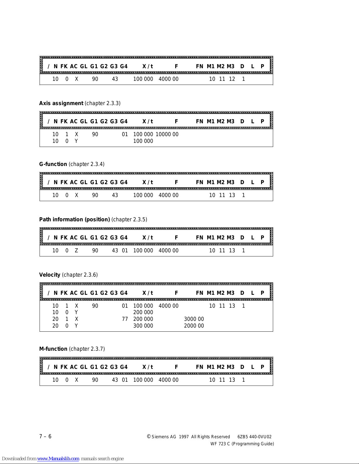
Programming in S5 Format 04.97
aaaaaaaaaaaaaaaaaaaaaaaaaaaaaaaaaaaaaaaaaaaaaaaaaaaaaaaaaaaaaaaaaaaaaaaaaaaaaaaaaaaaaaaaaaaaaaaaaaaaaaaaaaaaaaa
a
a
a
a
a
a
a
a
a
a
a
a
a
a
a
aaaaaaaaaaaaaaaaaaaaaaaaaaaaaaaaaaaaaaaaaaaaaaaaaaaaaaaaaaaaaaaaaaaaaaaaaaaaaaaaaaaaaaaaaaaaaaaaaaaaaaaaaaaaaaa
a
a
a
a
a
a
a
a
a
a
a
a
a
a
a
a
a
aaaaaaaaaaaaaaaaaaaaaaaaaaaaaaaaaaaaaaaaaaaaaaaaaaaaaaaaaaaaaaaaaaaaaaaaaaaaaaaaaaaaaaaaaaaaaaaaaaaaaaaaaaaaaaa
a
a
a
a
a
a
a
a
a
a
a
a
a
a
a
a
a
aaaaaaaaaaaaaaaaaaaaaaaaaaaaaaaaaaaaaaaaaaaaaaaaaaaaaaaaaaaaaaaaaaaaaaaaaaaaaaaaaaaaaaaaaaaaaaaaaaaaaaaaaaaaaaa
a
a
a
a
a
a
a
a
a
a
a
a
a
a
a
a
a
aaaaaaaaaaaaaaaaaaaaaaaaaaaaaaaaaaaaaaaaaaaaaaaaaaaaaaaaaaaaaaaaaaaaaaaaaaaaaaaaaaaaaaaaaaaaaaaaaaaaaaaaaaaaaaa
a
a
a
a
a
a
a
a
a
a
a
a
a
a
a
aaaaaaaaaaaaaaaaaaaaaaaaaaaaaaaaaaaaaaaaaaaaaaaaaaaaaaaaaaaaaaaaaaaaaaaaaaaaaaaaaaaaaaaaaaaaaaaaaaaaaaaaaaaaaaa
a
a
a
a
a
a
a
a
a
a
a
a
a
a
a
Block number (chapter 2.3.2)
aaaaaaaaaaaaaaaaaaaaaaaaaaaaaaaaaaaaaaaaaaaaaaaaaaaaaaaaaaaaaaaaaaaaaaaaaaaaaaaaaaaaaaaaaaaaaaaaaaaaaaaaaaaaa
aaaaaaaaaaaaaaaaaaaaaaaaaaaaaaaaaaaaaaaaaaaaaaaaaaaaaaaaaaaaaaaaaaaaaaaaaaaaaaaaaaaaaaaaaaaaaaaaaaaaaaaaaaaaa
aaaaaaaaaaaaaaaaaaaaaaaaaaaaaaaaaaaaaaaaaaaaaaaaaaaaaaaaaaaaaaaaaaaaaaaaaaaaaaaaaaaaaaaaaaaaaaaaaaaaaaaaaaaaa
aaaaaaaaaaaaaaaaaaaaaaaaaaaaaaaaaaaaaaaaaaaaaaaaaaaaaaaaaaaaaaaaaaaaaaaaaaaaaaaaaaaaaaaaaaaaaaaaaaaaaaaaaaaaa
aaaaaaaaaaaaaaaaaaaaaaaaaaaaaaaaaaaaaaaaaaaaaaaaaaaaaaaaaaaaaaaaaaaaaaaaaaaaaaaaaaaaaaaaaaaaaaaaaaaaaaaaaaaaa
/ N FK AC GL G1 G2 G3 G4 X / t F FN M1 M2 M3 D L P
aaaaaaaaaaaaaaaaaaaaaaaaaaaaaaaaaaaaaaaaaaaaaaaaaaaaaaaaaaaaaaaaaaaaaaaaaaaaaaaaaaaaaaaaaaaaaaaaaaaaaaaaaaaaa
aaaaaaaaaaaaaaaaaaaaaaaaaaaaaaaaaaaaaaaaaaaaaaaaaaaaaaaaaaaaaaaaaaaaaaaaaaaaaaaaaaaaaaaaaaaaaaaaaaaaaaaaaaaaa
10 0 X 90 43 100 000 4000 00 10 11 12 1
Axis assignment (chapter 2.3.3)
aaaaaaaaaaaaaaaaaaaaaaaaaaaaaaaaaaaaaaaaaaaaaaaaaaaaaaaaaaaaaaaaaaaaaaaaaaaaaaaaaaaaaaaaaaaaaaaaaaaaaaaaaaaaa
aaaaaaaaaaaaaaaaaaaaaaaaaaaaaaaaaaaaaaaaaaaaaaaaaaaaaaaaaaaaaaaaaaaaaaaaaaaaaaaaaaaaaaaaaaaaaaaaaaaaaaaaaaaaa
aaaaaaaaaaaaaaaaaaaaaaaaaaaaaaaaaaaaaaaaaaaaaaaaaaaaaaaaaaaaaaaaaaaaaaaaaaaaaaaaaaaaaaaaaaaaaaaaaaaaaaaaaaaaa
aaaaaaaaaaaaaaaaaaaaaaaaaaaaaaaaaaaaaaaaaaaaaaaaaaaaaaaaaaaaaaaaaaaaaaaaaaaaaaaaaaaaaaaaaaaaaaaaaaaaaaaaaaaaa
aaaaaaaaaaaaaaaaaaaaaaaaaaaaaaaaaaaaaaaaaaaaaaaaaaaaaaaaaaaaaaaaaaaaaaaaaaaaaaaaaaaaaaaaaaaaaaaaaaaaaaaaaaaaa
/ N FK AC GL G1 G2 G3 G4 X / t F FN M1 M2 M3 D L P
aaaaaaaaaaaaaaaaaaaaaaaaaaaaaaaaaaaaaaaaaaaaaaaaaaaaaaaaaaaaaaaaaaaaaaaaaaaaaaaaaaaaaaaaaaaaaaaaaaaaaaaaaaaaa
aaaaaaaaaaaaaaaaaaaaaaaaaaaaaaaaaaaaaaaaaaaaaaaaaaaaaaaaaaaaaaaaaaaaaaaaaaaaaaaaaaaaaaaaaaaaaaaaaaaaaaaaaaaaa
aaaaaaaaaaaaaaaaaaaaaaaaaaaaaaaaaaaaaaaaaaaaaaaaaaaaaaaaaaaaaaaaaaaaaaaaaaaaaaaaaaaaaaaaaaaaaaaaaaaaaaaaaaaaa
10 1 X 90 01 100 000 10000 00
10 0 Y 100 000
G-function (chapter 2.3.4)
aaaaaaaaaaaaaaaaaaaaaaaaaaaaaaaaaaaaaaaaaaaaaaaaaaaaaaaaaaaaaaaaaaaaaaaaaaaaaaaaaaaaaaaaaaaaaaaaaaaaaaaaaaaaa
aaaaaaaaaaaaaaaaaaaaaaaaaaaaaaaaaaaaaaaaaaaaaaaaaaaaaaaaaaaaaaaaaaaaaaaaaaaaaaaaaaaaaaaaaaaaaaaaaaaaaaaaaaaaa
aaaaaaaaaaaaaaaaaaaaaaaaaaaaaaaaaaaaaaaaaaaaaaaaaaaaaaaaaaaaaaaaaaaaaaaaaaaaaaaaaaaaaaaaaaaaaaaaaaaaaaaaaaaaa
aaaaaaaaaaaaaaaaaaaaaaaaaaaaaaaaaaaaaaaaaaaaaaaaaaaaaaaaaaaaaaaaaaaaaaaaaaaaaaaaaaaaaaaaaaaaaaaaaaaaaaaaaaaaa
aaaaaaaaaaaaaaaaaaaaaaaaaaaaaaaaaaaaaaaaaaaaaaaaaaaaaaaaaaaaaaaaaaaaaaaaaaaaaaaaaaaaaaaaaaaaaaaaaaaaaaaaaaaaa
/ N FK AC GL G1 G2 G3 G4 X / t F FN M1 M2 M3 D L P
aaaaaaaaaaaaaaaaaaaaaaaaaaaaaaaaaaaaaaaaaaaaaaaaaaaaaaaaaaaaaaaaaaaaaaaaaaaaaaaaaaaaaaaaaaaaaaaaaaaaaaaaaaaaa
aaaaaaaaaaaaaaaaaaaaaaaaaaaaaaaaaaaaaaaaaaaaaaaaaaaaaaaaaaaaaaaaaaaaaaaaaaaaaaaaaaaaaaaaaaaaaaaaaaaaaaaaaaaaa
aaaaaaaaaaaaaaaaaaaaaaaaaaaaaaaaaaaaaaaaaaaaaaaaaaaaaaaaaaaaaaaaaaaaaaaaaaaaaaaaaaaaaaaaaaaaaaaaaaaaaaaaaaaaa
10 0 X 90 43 100 000 4000 00 10 11 13 1
a
a
a
a
a
a
a
a
a
a
a
a
a
a
a
a
a
a
a
a
a
a
a
Path information (position) (chapter 2.3.5)
aaaaaaaaaaaaaaaaaaaaaaaaaaaaaaaaaaaaaaaaaaaaaaaaaaaaaaaaaaaaaaaaaaaaaaaaaaaaaaaaaaaaaaaaaaaaaaaaaaaaaaaaaaaaa
aaaaaaaaaaaaaaaaaaaaaaaaaaaaaaaaaaaaaaaaaaaaaaaaaaaaaaaaaaaaaaaaaaaaaaaaaaaaaaaaaaaaaaaaaaaaaaaaaaaaaaaaaaaaa
aaaaaaaaaaaaaaaaaaaaaaaaaaaaaaaaaaaaaaaaaaaaaaaaaaaaaaaaaaaaaaaaaaaaaaaaaaaaaaaaaaaaaaaaaaaaaaaaaaaaaaaaaaaaa
aaaaaaaaaaaaaaaaaaaaaaaaaaaaaaaaaaaaaaaaaaaaaaaaaaaaaaaaaaaaaaaaaaaaaaaaaaaaaaaaaaaaaaaaaaaaaaaaaaaaaaaaaaaaa
aaaaaaaaaaaaaaaaaaaaaaaaaaaaaaaaaaaaaaaaaaaaaaaaaaaaaaaaaaaaaaaaaaaaaaaaaaaaaaaaaaaaaaaaaaaaaaaaaaaaaaaaaaaaa
/ N FK AC GL G1 G2 G3 G4 X / t F FN M1 M2 M3 D L P
aaaaaaaaaaaaaaaaaaaaaaaaaaaaaaaaaaaaaaaaaaaaaaaaaaaaaaaaaaaaaaaaaaaaaaaaaaaaaaaaaaaaaaaaaaaaaaaaaaaaaaaaaaaaa
aaaaaaaaaaaaaaaaaaaaaaaaaaaaaaaaaaaaaaaaaaaaaaaaaaaaaaaaaaaaaaaaaaaaaaaaaaaaaaaaaaaaaaaaaaaaaaaaaaaaaaaaaaaaa
aaaaaaaaaaaaaaaaaaaaaaaaaaaaaaaaaaaaaaaaaaaaaaaaaaaaaaaaaaaaaaaaaaaaaaaaaaaaaaaaaaaaaaaaaaaaaaaaaaaaaaaaaaaaa
10 0 Z 90 43 01 100 000 4000 00 10 11 13 1
Velocity (chapter 2.3.6)
aaaaaaaaaaaaaaaaaaaaaaaaaaaaaaaaaaaaaaaaaaaaaaaaaaaaaaaaaaaaaaaaaaaaaaaaaaaaaaaaaaaaaaaaaaaaaaaaaaaaaaaaaaaaa
aaaaaaaaaaaaaaaaaaaaaaaaaaaaaaaaaaaaaaaaaaaaaaaaaaaaaaaaaaaaaaaaaaaaaaaaaaaaaaaaaaaaaaaaaaaaaaaaaaaaaaaaaaaaa
aaaaaaaaaaaaaaaaaaaaaaaaaaaaaaaaaaaaaaaaaaaaaaaaaaaaaaaaaaaaaaaaaaaaaaaaaaaaaaaaaaaaaaaaaaaaaaaaaaaaaaaaaaaaa
aaaaaaaaaaaaaaaaaaaaaaaaaaaaaaaaaaaaaaaaaaaaaaaaaaaaaaaaaaaaaaaaaaaaaaaaaaaaaaaaaaaaaaaaaaaaaaaaaaaaaaaaaaaaa
/ N FK AC GL G1 G2 G3 G4 X / t F FN M1 M2 M3 D L P
aaaaaaaaaaaaaaaaaaaaaaaaaaaaaaaaaaaaaaaaaaaaaaaaaaaaaaaaaaaaaaaaaaaaaaaaaaaaaaaaaaaaaaaaaaaaaaaaaaaaaaaaaaaaa
aaaaaaaaaaaaaaaaaaaaaaaaaaaaaaaaaaaaaaaaaaaaaaaaaaaaaaaaaaaaaaaaaaaaaaaaaaaaaaaaaaaaaaaaaaaaaaaaaaaaaaaaaaaaa
aaaaaaaaaaaaaaaaaaaaaaaaaaaaaaaaaaaaaaaaaaaaaaaaaaaaaaaaaaaaaaaaaaaaaaaaaaaaaaaaaaaaaaaaaaaaaaaaaaaaaaaaaaaaa
10 1 X 90 01 100 000 4000 00 10 11 13 1
10 0 Y 200 000
20 1 X 77 200 000 3000 00
20 0 Y 300 000 2000 00
M-function (chapter 2.3.7)
aaaaaaaaaaaaaaaaaaaaaaaaaaaaaaaaaaaaaaaaaaaaaaaaaaaaaaaaaaaaaaaaaaaaaaaaaaaaaaaaaaaaaaaaaaaaaaaaaaaaaaaaaaaaa
aaaaaaaaaaaaaaaaaaaaaaaaaaaaaaaaaaaaaaaaaaaaaaaaaaaaaaaaaaaaaaaaaaaaaaaaaaaaaaaaaaaaaaaaaaaaaaaaaaaaaaaaaaaaa
aaaaaaaaaaaaaaaaaaaaaaaaaaaaaaaaaaaaaaaaaaaaaaaaaaaaaaaaaaaaaaaaaaaaaaaaaaaaaaaaaaaaaaaaaaaaaaaaaaaaaaaaaaaaa
aaaaaaaaaaaaaaaaaaaaaaaaaaaaaaaaaaaaaaaaaaaaaaaaaaaaaaaaaaaaaaaaaaaaaaaaaaaaaaaaaaaaaaaaaaaaaaaaaaaaaaaaaaaaa
aaaaaaaaaaaaaaaaaaaaaaaaaaaaaaaaaaaaaaaaaaaaaaaaaaaaaaaaaaaaaaaaaaaaaaaaaaaaaaaaaaaaaaaaaaaaaaaaaaaaaaaaaaaaa
/ N FK AC GL G1 G2 G3 G4 X / t F FN M1 M2 M3 D L P
aaaaaaaaaaaaaaaaaaaaaaaaaaaaaaaaaaaaaaaaaaaaaaaaaaaaaaaaaaaaaaaaaaaaaaaaaaaaaaaaaaaaaaaaaaaaaaaaaaaaaaaaaaaaa
aaaaaaaaaaaaaaaaaaaaaaaaaaaaaaaaaaaaaaaaaaaaaaaaaaaaaaaaaaaaaaaaaaaaaaaaaaaaaaaaaaaaaaaaaaaaaaaaaaaaaaaaaaaaa
10 0 X 90 43 01 100 000 4000 00 10 11 13 1
a
a
a
a
a
a
a
a
a
a
a
a
a
a
a
a
a
a
a
a
a
a
7 – 6 ©
Siemens AG 1997 All Rights Reserved 6ZB5 440-0VU02
WF 723 C (Programming Guide)
Page 82
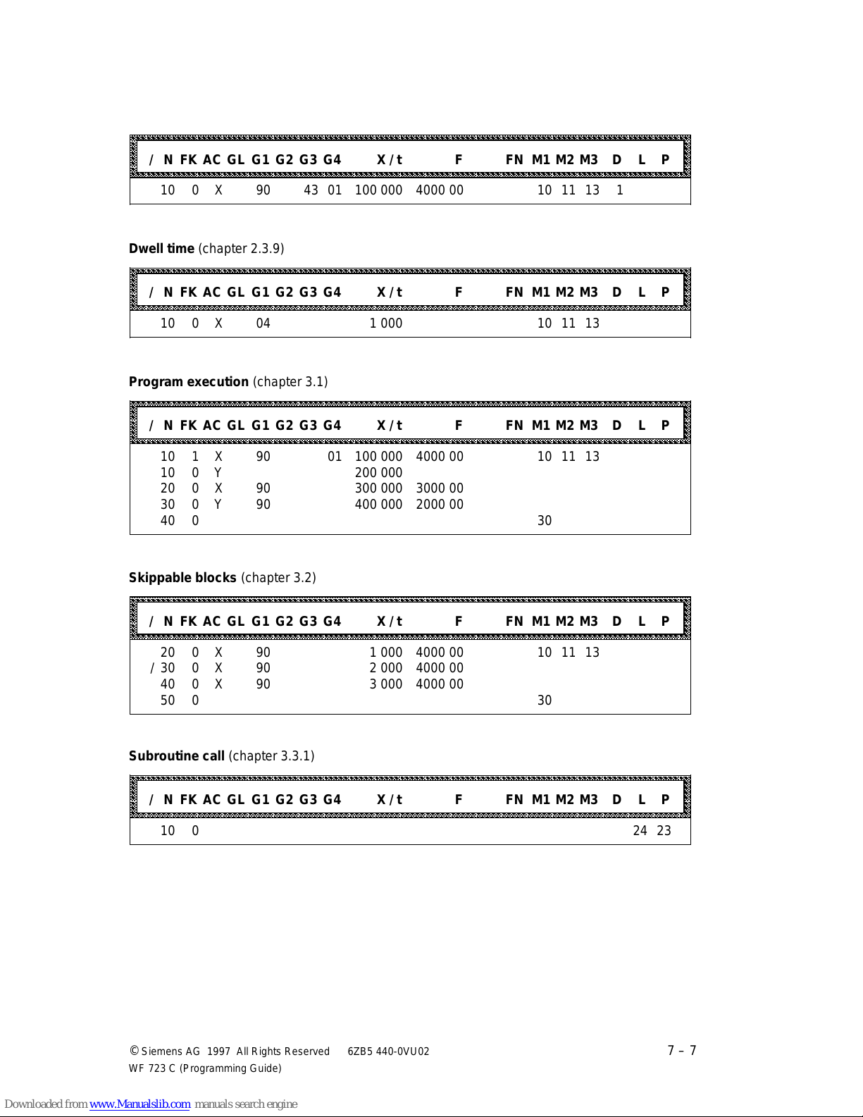
04.97 Programming in S5 Format
aaaaaaaaaaaaaaaaaaaaaaaaaaaaaaaaaaaaaaaaaaaaaaaaaaaaaaaaaaaaaaaaaaaaaaaaaaaaaaaaaaaaaaaaaaaaaaaaaaaaaaaaaaaaaaa
a
a
a
a
a
a
a
a
a
a
a
a
a
a
a
aaaaaaaaaaaaaaaaaaaaaaaaaaaaaaaaaaaaaaaaaaaaaaaaaaaaaaaaaaaaaaaaaaaaaaaaaaaaaaaaaaaaaaaaaaaaaaaaaaaaaaaaaaaaaaa
a
a
a
a
a
a
a
a
a
a
a
a
a
a
a
a
a
aaaaaaaaaaaaaaaaaaaaaaaaaaaaaaaaaaaaaaaaaaaaaaaaaaaaaaaaaaaaaaaaaaaaaaaaaaaaaaaaaaaaaaaaaaaaaaaaaaaaaaaaaaaaaaa
a
a
a
a
a
a
a
a
a
a
a
a
a
a
a
aaaaaaaaaaaaaaaaaaaaaaaaaaaaaaaaaaaaaaaaaaaaaaaaaaaaaaaaaaaaaaaaaaaaaaaaaaaaaaaaaaaaaaaaaaaaaaaaaaaaaaaaaaaaaaa
a
a
a
a
a
a
a
a
a
a
a
a
a
a
a
a
a
aaaaaaaaaaaaaaaaaaaaaaaaaaaaaaaaaaaaaaaaaaaaaaaaaaaaaaaaaaaaaaaaaaaaaaaaaaaaaaaaaaaaaaaaaaaaaaaaaaaaaaaaaaaaaaa
a
a
a
a
a
a
a
a
a
a
a
a
a
a
a
a
a
Tool offset number (chapter 2.3.8)
aaaaaaaaaaaaaaaaaaaaaaaaaaaaaaaaaaaaaaaaaaaaaaaaaaaaaaaaaaaaaaaaaaaaaaaaaaaaaaaaaaaaaaaaaaaaaaaaaaaaaaaaaaaaa
aaaaaaaaaaaaaaaaaaaaaaaaaaaaaaaaaaaaaaaaaaaaaaaaaaaaaaaaaaaaaaaaaaaaaaaaaaaaaaaaaaaaaaaaaaaaaaaaaaaaaaaaaaaaa
aaaaaaaaaaaaaaaaaaaaaaaaaaaaaaaaaaaaaaaaaaaaaaaaaaaaaaaaaaaaaaaaaaaaaaaaaaaaaaaaaaaaaaaaaaaaaaaaaaaaaaaaaaaaa
aaaaaaaaaaaaaaaaaaaaaaaaaaaaaaaaaaaaaaaaaaaaaaaaaaaaaaaaaaaaaaaaaaaaaaaaaaaaaaaaaaaaaaaaaaaaaaaaaaaaaaaaaaaaa
aaaaaaaaaaaaaaaaaaaaaaaaaaaaaaaaaaaaaaaaaaaaaaaaaaaaaaaaaaaaaaaaaaaaaaaaaaaaaaaaaaaaaaaaaaaaaaaaaaaaaaaaaaaaa
/ N FK AC GL G1 G2 G3 G4 X / t F FN M1 M2 M3 D L P
aaaaaaaaaaaaaaaaaaaaaaaaaaaaaaaaaaaaaaaaaaaaaaaaaaaaaaaaaaaaaaaaaaaaaaaaaaaaaaaaaaaaaaaaaaaaaaaaaaaaaaaaaaaaa
aaaaaaaaaaaaaaaaaaaaaaaaaaaaaaaaaaaaaaaaaaaaaaaaaaaaaaaaaaaaaaaaaaaaaaaaaaaaaaaaaaaaaaaaaaaaaaaaaaaaaaaaaaaaa
10 0 X 90 43 01 100 000 4000 00 10 11 13 1
Dwell time (chapter 2.3.9)
aaaaaaaaaaaaaaaaaaaaaaaaaaaaaaaaaaaaaaaaaaaaaaaaaaaaaaaaaaaaaaaaaaaaaaaaaaaaaaaaaaaaaaaaaaaaaaaaaaaaaaaaaaaaa
aaaaaaaaaaaaaaaaaaaaaaaaaaaaaaaaaaaaaaaaaaaaaaaaaaaaaaaaaaaaaaaaaaaaaaaaaaaaaaaaaaaaaaaaaaaaaaaaaaaaaaaaaaaaa
aaaaaaaaaaaaaaaaaaaaaaaaaaaaaaaaaaaaaaaaaaaaaaaaaaaaaaaaaaaaaaaaaaaaaaaaaaaaaaaaaaaaaaaaaaaaaaaaaaaaaaaaaaaaa
aaaaaaaaaaaaaaaaaaaaaaaaaaaaaaaaaaaaaaaaaaaaaaaaaaaaaaaaaaaaaaaaaaaaaaaaaaaaaaaaaaaaaaaaaaaaaaaaaaaaaaaaaaaaa
aaaaaaaaaaaaaaaaaaaaaaaaaaaaaaaaaaaaaaaaaaaaaaaaaaaaaaaaaaaaaaaaaaaaaaaaaaaaaaaaaaaaaaaaaaaaaaaaaaaaaaaaaaaaa
/ N FK AC GL G1 G2 G3 G4 X / t F FN M1 M2 M3 D L P
aaaaaaaaaaaaaaaaaaaaaaaaaaaaaaaaaaaaaaaaaaaaaaaaaaaaaaaaaaaaaaaaaaaaaaaaaaaaaaaaaaaaaaaaaaaaaaaaaaaaaaaaaaaaa
aaaaaaaaaaaaaaaaaaaaaaaaaaaaaaaaaaaaaaaaaaaaaaaaaaaaaaaaaaaaaaaaaaaaaaaaaaaaaaaaaaaaaaaaaaaaaaaaaaaaaaaaaaaaa
aaaaaaaaaaaaaaaaaaaaaaaaaaaaaaaaaaaaaaaaaaaaaaaaaaaaaaaaaaaaaaaaaaaaaaaaaaaaaaaaaaaaaaaaaaaaaaaaaaaaaaaaaaaaa
10 0 X 04 1 000 10 11 13
Program execution (chapter 3.1)
a
a
a
a
a
a
a
a
a
a
a
a
a
a
a
aaaaaaaaaaaaaaaaaaaaaaaaaaaaaaaaaaaaaaaaaaaaaaaaaaaaaaaaaaaaaaaaaaaaaaaaaaaaaaaaaaaaaaaaaaaaaaaaaaaaaaaaaaaaa
aaaaaaaaaaaaaaaaaaaaaaaaaaaaaaaaaaaaaaaaaaaaaaaaaaaaaaaaaaaaaaaaaaaaaaaaaaaaaaaaaaaaaaaaaaaaaaaaaaaaaaaaaaaaa
aaaaaaaaaaaaaaaaaaaaaaaaaaaaaaaaaaaaaaaaaaaaaaaaaaaaaaaaaaaaaaaaaaaaaaaaaaaaaaaaaaaaaaaaaaaaaaaaaaaaaaaaaaaaa
aaaaaaaaaaaaaaaaaaaaaaaaaaaaaaaaaaaaaaaaaaaaaaaaaaaaaaaaaaaaaaaaaaaaaaaaaaaaaaaaaaaaaaaaaaaaaaaaaaaaaaaaaaaaa
/ N FK AC GL G1 G2 G3 G4 X / t F FN M1 M2 M3 D L P
aaaaaaaaaaaaaaaaaaaaaaaaaaaaaaaaaaaaaaaaaaaaaaaaaaaaaaaaaaaaaaaaaaaaaaaaaaaaaaaaaaaaaaaaaaaaaaaaaaaaaaaaaaaaa
aaaaaaaaaaaaaaaaaaaaaaaaaaaaaaaaaaaaaaaaaaaaaaaaaaaaaaaaaaaaaaaaaaaaaaaaaaaaaaaaaaaaaaaaaaaaaaaaaaaaaaaaaaaaa
aaaaaaaaaaaaaaaaaaaaaaaaaaaaaaaaaaaaaaaaaaaaaaaaaaaaaaaaaaaaaaaaaaaaaaaaaaaaaaaaaaaaaaaaaaaaaaaaaaaaaaaaaaaaa
10 1 X 90 01 100 000 4000 00 10 11 13
10 0 Y 200 000
20 0 X 90 300 000 3000 00
30 0 Y 90 400 000 2000 00
40 0 30
Skippable blocks (chapter 3.2)
aaaaaaaaaaaaaaaaaaaaaaaaaaaaaaaaaaaaaaaaaaaaaaaaaaaaaaaaaaaaaaaaaaaaaaaaaaaaaaaaaaaaaaaaaaaaaaaaaaaaaaaaaaaaa
aaaaaaaaaaaaaaaaaaaaaaaaaaaaaaaaaaaaaaaaaaaaaaaaaaaaaaaaaaaaaaaaaaaaaaaaaaaaaaaaaaaaaaaaaaaaaaaaaaaaaaaaaaaaa
aaaaaaaaaaaaaaaaaaaaaaaaaaaaaaaaaaaaaaaaaaaaaaaaaaaaaaaaaaaaaaaaaaaaaaaaaaaaaaaaaaaaaaaaaaaaaaaaaaaaaaaaaaaaa
aaaaaaaaaaaaaaaaaaaaaaaaaaaaaaaaaaaaaaaaaaaaaaaaaaaaaaaaaaaaaaaaaaaaaaaaaaaaaaaaaaaaaaaaaaaaaaaaaaaaaaaaaaaaa
aaaaaaaaaaaaaaaaaaaaaaaaaaaaaaaaaaaaaaaaaaaaaaaaaaaaaaaaaaaaaaaaaaaaaaaaaaaaaaaaaaaaaaaaaaaaaaaaaaaaaaaaaaaaa
/ N FK AC GL G1 G2 G3 G4 X / t F FN M1 M2 M3 D L P
aaaaaaaaaaaaaaaaaaaaaaaaaaaaaaaaaaaaaaaaaaaaaaaaaaaaaaaaaaaaaaaaaaaaaaaaaaaaaaaaaaaaaaaaaaaaaaaaaaaaaaaaaaaaa
aaaaaaaaaaaaaaaaaaaaaaaaaaaaaaaaaaaaaaaaaaaaaaaaaaaaaaaaaaaaaaaaaaaaaaaaaaaaaaaaaaaaaaaaaaaaaaaaaaaaaaaaaaaaa
aaaaaaaaaaaaaaaaaaaaaaaaaaaaaaaaaaaaaaaaaaaaaaaaaaaaaaaaaaaaaaaaaaaaaaaaaaaaaaaaaaaaaaaaaaaaaaaaaaaaaaaaaaaaa
20 0 X 90 1 000 4000 00 10 11 13
/ 30 0 X 90 2 000 4000 00
40 0 X 90 3 000 4000 00
50 0 30
Subroutine call (chapter 3.3.1)
aaaaaaaaaaaaaaaaaaaaaaaaaaaaaaaaaaaaaaaaaaaaaaaaaaaaaaaaaaaaaaaaaaaaaaaaaaaaaaaaaaaaaaaaaaaaaaaaaaaaaaaaaaaaa
aaaaaaaaaaaaaaaaaaaaaaaaaaaaaaaaaaaaaaaaaaaaaaaaaaaaaaaaaaaaaaaaaaaaaaaaaaaaaaaaaaaaaaaaaaaaaaaaaaaaaaaaaaaaa
aaaaaaaaaaaaaaaaaaaaaaaaaaaaaaaaaaaaaaaaaaaaaaaaaaaaaaaaaaaaaaaaaaaaaaaaaaaaaaaaaaaaaaaaaaaaaaaaaaaaaaaaaaaaa
aaaaaaaaaaaaaaaaaaaaaaaaaaaaaaaaaaaaaaaaaaaaaaaaaaaaaaaaaaaaaaaaaaaaaaaaaaaaaaaaaaaaaaaaaaaaaaaaaaaaaaaaaaaaa
aaaaaaaaaaaaaaaaaaaaaaaaaaaaaaaaaaaaaaaaaaaaaaaaaaaaaaaaaaaaaaaaaaaaaaaaaaaaaaaaaaaaaaaaaaaaaaaaaaaaaaaaaaaaa
/ N FK AC GL G1 G2 G3 G4 X / t F FN M1 M2 M3 D L P
aaaaaaaaaaaaaaaaaaaaaaaaaaaaaaaaaaaaaaaaaaaaaaaaaaaaaaaaaaaaaaaaaaaaaaaaaaaaaaaaaaaaaaaaaaaaaaaaaaaaaaaaaaaaa
aaaaaaaaaaaaaaaaaaaaaaaaaaaaaaaaaaaaaaaaaaaaaaaaaaaaaaaaaaaaaaaaaaaaaaaaaaaaaaaaaaaaaaaaaaaaaaaaaaaaaaaaaaaaa
aaaaaaaaaaaaaaaaaaaaaaaaaaaaaaaaaaaaaaaaaaaaaaaaaaaaaaaaaaaaaaaaaaaaaaaaaaaaaaaaaaaaaaaaaaaaaaaaaaaaaaaaaaaaa
10 0 24 23
a
a
a
a
a
a
a
a
a
a
a
a
a
a
a
a
a
a
a
a
a
a
a
©
Siemens AG 1997 All Rights Reserved 6ZB5 440-0VU02
WF 723 C (Programming Guide)
7 – 7
Page 83
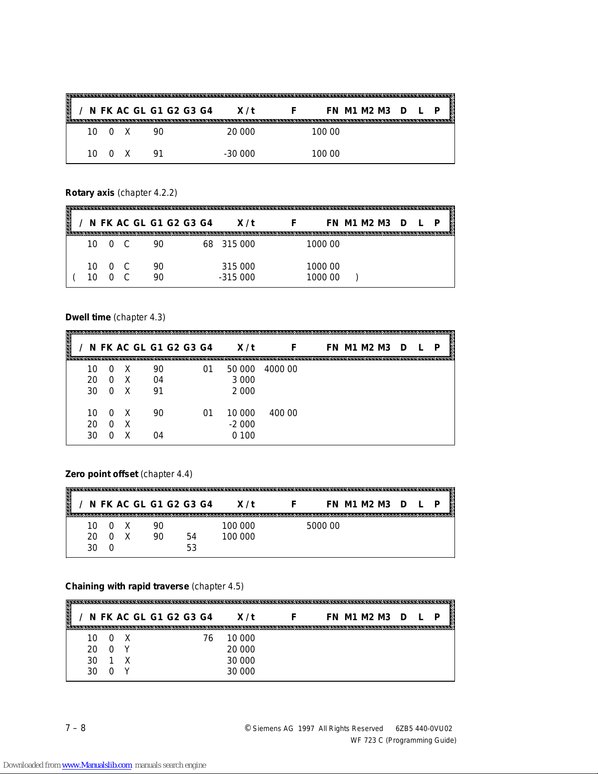
Programming in S5 Format 04.97
aaaaaaaaaaaaaaaaaaaaaaaaaaaaaaaaaaaaaaaaaaaaaaaaaaaaaaaaaaaaaaaaaaaaaaaaaaaaaaaaaaaaaaaaaaaaaaaaaaaaaaaaaaaaaaa
a
a
a
a
a
a
a
a
a
a
a
a
a
a
a
aaaaaaaaaaaaaaaaaaaaaaaaaaaaaaaaaaaaaaaaaaaaaaaaaaaaaaaaaaaaaaaaaaaaaaaaaaaaaaaaaaaaaaaaaaaaaaaaaaaaaaaaaaaaaaa
a
a
a
a
a
a
a
a
a
a
a
a
a
a
a
aaaaaaaaaaaaaaaaaaaaaaaaaaaaaaaaaaaaaaaaaaaaaaaaaaaaaaaaaaaaaaaaaaaaaaaaaaaaaaaaaaaaaaaaaaaaaaaaaaaaaaaaaaaaaaa
a
a
a
a
a
a
a
a
a
a
a
a
a
a
a
a
a
aaaaaaaaaaaaaaaaaaaaaaaaaaaaaaaaaaaaaaaaaaaaaaaaaaaaaaaaaaaaaaaaaaaaaaaaaaaaaaaaaaaaaaaaaaaaaaaaaaaaaaaaaaaaaaa
a
a
a
a
a
a
a
a
a
a
a
a
a
a
a
a
a
aaaaaaaaaaaaaaaaaaaaaaaaaaaaaaaaaaaaaaaaaaaaaaaaaaaaaaaaaaaaaaaaaaaaaaaaaaaaaaaaaaaaaaaaaaaaaaaaaaaaaaaaaaaaaaa
a
a
a
a
a
a
a
a
a
a
a
a
a
a
a
a
a
Linear axis (chapter 4.2.1)
aaaaaaaaaaaaaaaaaaaaaaaaaaaaaaaaaaaaaaaaaaaaaaaaaaaaaaaaaaaaaaaaaaaaaaaaaaaaaaaaaaaaaaaaaaaaaaaaaaaaaaaaaaaaa
aaaaaaaaaaaaaaaaaaaaaaaaaaaaaaaaaaaaaaaaaaaaaaaaaaaaaaaaaaaaaaaaaaaaaaaaaaaaaaaaaaaaaaaaaaaaaaaaaaaaaaaaaaaaa
aaaaaaaaaaaaaaaaaaaaaaaaaaaaaaaaaaaaaaaaaaaaaaaaaaaaaaaaaaaaaaaaaaaaaaaaaaaaaaaaaaaaaaaaaaaaaaaaaaaaaaaaaaaaa
aaaaaaaaaaaaaaaaaaaaaaaaaaaaaaaaaaaaaaaaaaaaaaaaaaaaaaaaaaaaaaaaaaaaaaaaaaaaaaaaaaaaaaaaaaaaaaaaaaaaaaaaaaaaa
aaaaaaaaaaaaaaaaaaaaaaaaaaaaaaaaaaaaaaaaaaaaaaaaaaaaaaaaaaaaaaaaaaaaaaaaaaaaaaaaaaaaaaaaaaaaaaaaaaaaaaaaaaaaa
/ N FK AC GL G1 G2 G3 G4 X / t F FN M1 M2 M3 D L P
aaaaaaaaaaaaaaaaaaaaaaaaaaaaaaaaaaaaaaaaaaaaaaaaaaaaaaaaaaaaaaaaaaaaaaaaaaaaaaaaaaaaaaaaaaaaaaaaaaaaaaaaaaaaa
aaaaaaaaaaaaaaaaaaaaaaaaaaaaaaaaaaaaaaaaaaaaaaaaaaaaaaaaaaaaaaaaaaaaaaaaaaaaaaaaaaaaaaaaaaaaaaaaaaaaaaaaaaaaa
10 0 X 90 20 000 100 00
10 0 X 91 -30 000 100 00
Rotary axis (chapter 4.2.2)
aaaaaaaaaaaaaaaaaaaaaaaaaaaaaaaaaaaaaaaaaaaaaaaaaaaaaaaaaaaaaaaaaaaaaaaaaaaaaaaaaaaaaaaaaaaaaaaaaaaaaaaaaaaaa
aaaaaaaaaaaaaaaaaaaaaaaaaaaaaaaaaaaaaaaaaaaaaaaaaaaaaaaaaaaaaaaaaaaaaaaaaaaaaaaaaaaaaaaaaaaaaaaaaaaaaaaaaaaaa
aaaaaaaaaaaaaaaaaaaaaaaaaaaaaaaaaaaaaaaaaaaaaaaaaaaaaaaaaaaaaaaaaaaaaaaaaaaaaaaaaaaaaaaaaaaaaaaaaaaaaaaaaaaaa
aaaaaaaaaaaaaaaaaaaaaaaaaaaaaaaaaaaaaaaaaaaaaaaaaaaaaaaaaaaaaaaaaaaaaaaaaaaaaaaaaaaaaaaaaaaaaaaaaaaaaaaaaaaaa
aaaaaaaaaaaaaaaaaaaaaaaaaaaaaaaaaaaaaaaaaaaaaaaaaaaaaaaaaaaaaaaaaaaaaaaaaaaaaaaaaaaaaaaaaaaaaaaaaaaaaaaaaaaaa
/ N FK AC GL G1 G2 G3 G4 X / t F FN M1 M2 M3 D L P
aaaaaaaaaaaaaaaaaaaaaaaaaaaaaaaaaaaaaaaaaaaaaaaaaaaaaaaaaaaaaaaaaaaaaaaaaaaaaaaaaaaaaaaaaaaaaaaaaaaaaaaaaaaaa
aaaaaaaaaaaaaaaaaaaaaaaaaaaaaaaaaaaaaaaaaaaaaaaaaaaaaaaaaaaaaaaaaaaaaaaaaaaaaaaaaaaaaaaaaaaaaaaaaaaaaaaaaaaaa
10 0 C 90 68 315 000 1000 00
10 0 C 90 315 000 1000 00
( 10 0 C 90 -315 000 1000 00 )
a
a
a
a
a
a
a
a
a
a
a
a
a
a
Dwell time (chapter 4.3)
aaaaaaaaaaaaaaaaaaaaaaaaaaaaaaaaaaaaaaaaaaaaaaaaaaaaaaaaaaaaaaaaaaaaaaaaaaaaaaaaaaaaaaaaaaaaaaaaaaaaaaaaaaaaa
aaaaaaaaaaaaaaaaaaaaaaaaaaaaaaaaaaaaaaaaaaaaaaaaaaaaaaaaaaaaaaaaaaaaaaaaaaaaaaaaaaaaaaaaaaaaaaaaaaaaaaaaaaaaa
aaaaaaaaaaaaaaaaaaaaaaaaaaaaaaaaaaaaaaaaaaaaaaaaaaaaaaaaaaaaaaaaaaaaaaaaaaaaaaaaaaaaaaaaaaaaaaaaaaaaaaaaaaaaa
aaaaaaaaaaaaaaaaaaaaaaaaaaaaaaaaaaaaaaaaaaaaaaaaaaaaaaaaaaaaaaaaaaaaaaaaaaaaaaaaaaaaaaaaaaaaaaaaaaaaaaaaaaaaa
aaaaaaaaaaaaaaaaaaaaaaaaaaaaaaaaaaaaaaaaaaaaaaaaaaaaaaaaaaaaaaaaaaaaaaaaaaaaaaaaaaaaaaaaaaaaaaaaaaaaaaaaaaaaa
/ N FK AC GL G1 G2 G3 G4 X / t F FN M1 M2 M3 D L P
aaaaaaaaaaaaaaaaaaaaaaaaaaaaaaaaaaaaaaaaaaaaaaaaaaaaaaaaaaaaaaaaaaaaaaaaaaaaaaaaaaaaaaaaaaaaaaaaaaaaaaaaaaaaa
aaaaaaaaaaaaaaaaaaaaaaaaaaaaaaaaaaaaaaaaaaaaaaaaaaaaaaaaaaaaaaaaaaaaaaaaaaaaaaaaaaaaaaaaaaaaaaaaaaaaaaaaaaaaa
aaaaaaaaaaaaaaaaaaaaaaaaaaaaaaaaaaaaaaaaaaaaaaaaaaaaaaaaaaaaaaaaaaaaaaaaaaaaaaaaaaaaaaaaaaaaaaaaaaaaaaaaaaaaa
10 0 X 90 01 50 000 4000 00
20 0 X 04 3 000
30 0 X 91 2 000
10 0 X 90 01 10 000 400 00
20 0 X -2 000
30 0 X 04 0 100
Zero point offset (chapter 4.4)
aaaaaaaaaaaaaaaaaaaaaaaaaaaaaaaaaaaaaaaaaaaaaaaaaaaaaaaaaaaaaaaaaaaaaaaaaaaaaaaaaaaaaaaaaaaaaaaaaaaaaaaaaaaaa
aaaaaaaaaaaaaaaaaaaaaaaaaaaaaaaaaaaaaaaaaaaaaaaaaaaaaaaaaaaaaaaaaaaaaaaaaaaaaaaaaaaaaaaaaaaaaaaaaaaaaaaaaaaaa
aaaaaaaaaaaaaaaaaaaaaaaaaaaaaaaaaaaaaaaaaaaaaaaaaaaaaaaaaaaaaaaaaaaaaaaaaaaaaaaaaaaaaaaaaaaaaaaaaaaaaaaaaaaaa
aaaaaaaaaaaaaaaaaaaaaaaaaaaaaaaaaaaaaaaaaaaaaaaaaaaaaaaaaaaaaaaaaaaaaaaaaaaaaaaaaaaaaaaaaaaaaaaaaaaaaaaaaaaaa
aaaaaaaaaaaaaaaaaaaaaaaaaaaaaaaaaaaaaaaaaaaaaaaaaaaaaaaaaaaaaaaaaaaaaaaaaaaaaaaaaaaaaaaaaaaaaaaaaaaaaaaaaaaaa
/ N FK AC GL G1 G2 G3 G4 X / t F FN M1 M2 M3 D L P
aaaaaaaaaaaaaaaaaaaaaaaaaaaaaaaaaaaaaaaaaaaaaaaaaaaaaaaaaaaaaaaaaaaaaaaaaaaaaaaaaaaaaaaaaaaaaaaaaaaaaaaaaaaaa
aaaaaaaaaaaaaaaaaaaaaaaaaaaaaaaaaaaaaaaaaaaaaaaaaaaaaaaaaaaaaaaaaaaaaaaaaaaaaaaaaaaaaaaaaaaaaaaaaaaaaaaaaaaaa
aaaaaaaaaaaaaaaaaaaaaaaaaaaaaaaaaaaaaaaaaaaaaaaaaaaaaaaaaaaaaaaaaaaaaaaaaaaaaaaaaaaaaaaaaaaaaaaaaaaaaaaaaaaaa
10 0 X 90 100 000 5000 00
20 0 X 90 54 100 000
30 0 53
Chaining with rapid traverse (chapter 4.5)
aaaaaaaaaaaaaaaaaaaaaaaaaaaaaaaaaaaaaaaaaaaaaaaaaaaaaaaaaaaaaaaaaaaaaaaaaaaaaaaaaaaaaaaaaaaaaaaaaaaaaaaaaaaaa
aaaaaaaaaaaaaaaaaaaaaaaaaaaaaaaaaaaaaaaaaaaaaaaaaaaaaaaaaaaaaaaaaaaaaaaaaaaaaaaaaaaaaaaaaaaaaaaaaaaaaaaaaaaaa
aaaaaaaaaaaaaaaaaaaaaaaaaaaaaaaaaaaaaaaaaaaaaaaaaaaaaaaaaaaaaaaaaaaaaaaaaaaaaaaaaaaaaaaaaaaaaaaaaaaaaaaaaaaaa
aaaaaaaaaaaaaaaaaaaaaaaaaaaaaaaaaaaaaaaaaaaaaaaaaaaaaaaaaaaaaaaaaaaaaaaaaaaaaaaaaaaaaaaaaaaaaaaaaaaaaaaaaaaaa
aaaaaaaaaaaaaaaaaaaaaaaaaaaaaaaaaaaaaaaaaaaaaaaaaaaaaaaaaaaaaaaaaaaaaaaaaaaaaaaaaaaaaaaaaaaaaaaaaaaaaaaaaaaaa
/ N FK AC GL G1 G2 G3 G4 X / t F FN M1 M2 M3 D L P
aaaaaaaaaaaaaaaaaaaaaaaaaaaaaaaaaaaaaaaaaaaaaaaaaaaaaaaaaaaaaaaaaaaaaaaaaaaaaaaaaaaaaaaaaaaaaaaaaaaaaaaaaaaaa
aaaaaaaaaaaaaaaaaaaaaaaaaaaaaaaaaaaaaaaaaaaaaaaaaaaaaaaaaaaaaaaaaaaaaaaaaaaaaaaaaaaaaaaaaaaaaaaaaaaaaaaaaaaaa
aaaaaaaaaaaaaaaaaaaaaaaaaaaaaaaaaaaaaaaaaaaaaaaaaaaaaaaaaaaaaaaaaaaaaaaaaaaaaaaaaaaaaaaaaaaaaaaaaaaaaaaaaaaaa
10 0 X 76 10 000
20 0 Y 20 000
30 1 X 30 000
30 0 Y 30 000
a
a
a
a
a
a
a
a
a
a
a
a
a
a
a
a
a
a
a
a
a
a
a
a
7 – 8 ©
Siemens AG 1997 All Rights Reserved 6ZB5 440-0VU02
WF 723 C (Programming Guide)
Page 84
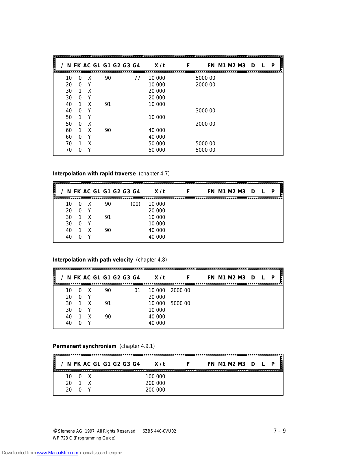
04.97 Programming in S5 Format
aaaaaaaaaaaaaaaaaaaaaaaaaaaaaaaaaaaaaaaaaaaaaaaaaaaaaaaaaaaaaaaaaaaaaaaaaaaaaaaaaaaaaaaaaaaaaaaaaaaaaaaaaaaaaaa
a
a
a
a
a
a
a
a
a
a
a
a
a
a
a
aaaaaaaaaaaaaaaaaaaaaaaaaaaaaaaaaaaaaaaaaaaaaaaaaaaaaaaaaaaaaaaaaaaaaaaaaaaaaaaaaaaaaaaaaaaaaaaaaaaaaaaaaaaaaaa
a
a
a
a
a
a
a
a
a
a
a
a
a
a
a
aaaaaaaaaaaaaaaaaaaaaaaaaaaaaaaaaaaaaaaaaaaaaaaaaaaaaaaaaaaaaaaaaaaaaaaaaaaaaaaaaaaaaaaaaaaaaaaaaaaaaaaaaaaaaaa
a
a
a
a
a
a
a
a
a
a
a
a
a
a
a
a
a
aaaaaaaaaaaaaaaaaaaaaaaaaaaaaaaaaaaaaaaaaaaaaaaaaaaaaaaaaaaaaaaaaaaaaaaaaaaaaaaaaaaaaaaaaaaaaaaaaaaaaaaaaaaaaaa
a
a
a
a
a
a
a
a
a
a
a
a
a
a
a
Chaining with axis velocity (chapter 4.6)
aaaaaaaaaaaaaaaaaaaaaaaaaaaaaaaaaaaaaaaaaaaaaaaaaaaaaaaaaaaaaaaaaaaaaaaaaaaaaaaaaaaaaaaaaaaaaaaaaaaaaaaaaaaaa
aaaaaaaaaaaaaaaaaaaaaaaaaaaaaaaaaaaaaaaaaaaaaaaaaaaaaaaaaaaaaaaaaaaaaaaaaaaaaaaaaaaaaaaaaaaaaaaaaaaaaaaaaaaaa
aaaaaaaaaaaaaaaaaaaaaaaaaaaaaaaaaaaaaaaaaaaaaaaaaaaaaaaaaaaaaaaaaaaaaaaaaaaaaaaaaaaaaaaaaaaaaaaaaaaaaaaaaaaaa
aaaaaaaaaaaaaaaaaaaaaaaaaaaaaaaaaaaaaaaaaaaaaaaaaaaaaaaaaaaaaaaaaaaaaaaaaaaaaaaaaaaaaaaaaaaaaaaaaaaaaaaaaaaaa
aaaaaaaaaaaaaaaaaaaaaaaaaaaaaaaaaaaaaaaaaaaaaaaaaaaaaaaaaaaaaaaaaaaaaaaaaaaaaaaaaaaaaaaaaaaaaaaaaaaaaaaaaaaaa
/ N FK AC GL G1 G2 G3 G4 X / t F FN M1 M2 M3 D L P
aaaaaaaaaaaaaaaaaaaaaaaaaaaaaaaaaaaaaaaaaaaaaaaaaaaaaaaaaaaaaaaaaaaaaaaaaaaaaaaaaaaaaaaaaaaaaaaaaaaaaaaaaaaaa
aaaaaaaaaaaaaaaaaaaaaaaaaaaaaaaaaaaaaaaaaaaaaaaaaaaaaaaaaaaaaaaaaaaaaaaaaaaaaaaaaaaaaaaaaaaaaaaaaaaaaaaaaaaaa
10 0 X 90 77 10 000 5000 00
20 0 Y 10 000 2000 00
30 1 X 20 000
30 0 Y 20 000
40 1 X 91 10 000
40 0 Y 3000 00
50 1 Y 10 000
50 0 X 2000 00
60 1 X 90 40 000
60 0 Y 40 000
70 1 X 50 000 5000 00
70 0 Y 50 000 5000 00
Interpolation with rapid traverse (chapter 4.7)
aaaaaaaaaaaaaaaaaaaaaaaaaaaaaaaaaaaaaaaaaaaaaaaaaaaaaaaaaaaaaaaaaaaaaaaaaaaaaaaaaaaaaaaaaaaaaaaaaaaaaaaaaaaaa
aaaaaaaaaaaaaaaaaaaaaaaaaaaaaaaaaaaaaaaaaaaaaaaaaaaaaaaaaaaaaaaaaaaaaaaaaaaaaaaaaaaaaaaaaaaaaaaaaaaaaaaaaaaaa
aaaaaaaaaaaaaaaaaaaaaaaaaaaaaaaaaaaaaaaaaaaaaaaaaaaaaaaaaaaaaaaaaaaaaaaaaaaaaaaaaaaaaaaaaaaaaaaaaaaaaaaaaaaaa
aaaaaaaaaaaaaaaaaaaaaaaaaaaaaaaaaaaaaaaaaaaaaaaaaaaaaaaaaaaaaaaaaaaaaaaaaaaaaaaaaaaaaaaaaaaaaaaaaaaaaaaaaaaaa
/ N FK AC GL G1 G2 G3 G4 X / t F FN M1 M2 M3 D L P
aaaaaaaaaaaaaaaaaaaaaaaaaaaaaaaaaaaaaaaaaaaaaaaaaaaaaaaaaaaaaaaaaaaaaaaaaaaaaaaaaaaaaaaaaaaaaaaaaaaaaaaaaaaaa
aaaaaaaaaaaaaaaaaaaaaaaaaaaaaaaaaaaaaaaaaaaaaaaaaaaaaaaaaaaaaaaaaaaaaaaaaaaaaaaaaaaaaaaaaaaaaaaaaaaaaaaaaaaaa
aaaaaaaaaaaaaaaaaaaaaaaaaaaaaaaaaaaaaaaaaaaaaaaaaaaaaaaaaaaaaaaaaaaaaaaaaaaaaaaaaaaaaaaaaaaaaaaaaaaaaaaaaaaaa
10 0 X 90 (00) 10 000
20 0 Y 20 000
30 1 X 91 10 000
30 0 Y 10 000
40 1 X 90 40 000
40 0 Y 40 000
a
a
a
a
a
a
a
a
a
a
a
a
a
a
Interpolation with path velocity (chapter 4.8)
aaaaaaaaaaaaaaaaaaaaaaaaaaaaaaaaaaaaaaaaaaaaaaaaaaaaaaaaaaaaaaaaaaaaaaaaaaaaaaaaaaaaaaaaaaaaaaaaaaaaaaaaaaaaa
aaaaaaaaaaaaaaaaaaaaaaaaaaaaaaaaaaaaaaaaaaaaaaaaaaaaaaaaaaaaaaaaaaaaaaaaaaaaaaaaaaaaaaaaaaaaaaaaaaaaaaaaaaaaa
aaaaaaaaaaaaaaaaaaaaaaaaaaaaaaaaaaaaaaaaaaaaaaaaaaaaaaaaaaaaaaaaaaaaaaaaaaaaaaaaaaaaaaaaaaaaaaaaaaaaaaaaaaaaa
aaaaaaaaaaaaaaaaaaaaaaaaaaaaaaaaaaaaaaaaaaaaaaaaaaaaaaaaaaaaaaaaaaaaaaaaaaaaaaaaaaaaaaaaaaaaaaaaaaaaaaaaaaaaa
aaaaaaaaaaaaaaaaaaaaaaaaaaaaaaaaaaaaaaaaaaaaaaaaaaaaaaaaaaaaaaaaaaaaaaaaaaaaaaaaaaaaaaaaaaaaaaaaaaaaaaaaaaaaa
/ N FK AC GL G1 G2 G3 G4 X / t F FN M1 M2 M3 D L P
aaaaaaaaaaaaaaaaaaaaaaaaaaaaaaaaaaaaaaaaaaaaaaaaaaaaaaaaaaaaaaaaaaaaaaaaaaaaaaaaaaaaaaaaaaaaaaaaaaaaaaaaaaaaa
aaaaaaaaaaaaaaaaaaaaaaaaaaaaaaaaaaaaaaaaaaaaaaaaaaaaaaaaaaaaaaaaaaaaaaaaaaaaaaaaaaaaaaaaaaaaaaaaaaaaaaaaaaaaa
aaaaaaaaaaaaaaaaaaaaaaaaaaaaaaaaaaaaaaaaaaaaaaaaaaaaaaaaaaaaaaaaaaaaaaaaaaaaaaaaaaaaaaaaaaaaaaaaaaaaaaaaaaaaa
10 0 X 90 01 10 000 2000 00
20 0 Y 20 000
30 1 X 91 10 000 5000 00
30 0 Y 10 000
40 1 X 90 40 000
40 0 Y 40 000
Permanent synchronism (chapter 4.9.1)
aaaaaaaaaaaaaaaaaaaaaaaaaaaaaaaaaaaaaaaaaaaaaaaaaaaaaaaaaaaaaaaaaaaaaaaaaaaaaaaaaaaaaaaaaaaaaaaaaaaaaaaaaaaaa
aaaaaaaaaaaaaaaaaaaaaaaaaaaaaaaaaaaaaaaaaaaaaaaaaaaaaaaaaaaaaaaaaaaaaaaaaaaaaaaaaaaaaaaaaaaaaaaaaaaaaaaaaaaaa
aaaaaaaaaaaaaaaaaaaaaaaaaaaaaaaaaaaaaaaaaaaaaaaaaaaaaaaaaaaaaaaaaaaaaaaaaaaaaaaaaaaaaaaaaaaaaaaaaaaaaaaaaaaaa
aaaaaaaaaaaaaaaaaaaaaaaaaaaaaaaaaaaaaaaaaaaaaaaaaaaaaaaaaaaaaaaaaaaaaaaaaaaaaaaaaaaaaaaaaaaaaaaaaaaaaaaaaaaaa
/ N FK AC GL G1 G2 G3 G4 X / t F FN M1 M2 M3 D L P
aaaaaaaaaaaaaaaaaaaaaaaaaaaaaaaaaaaaaaaaaaaaaaaaaaaaaaaaaaaaaaaaaaaaaaaaaaaaaaaaaaaaaaaaaaaaaaaaaaaaaaaaaaaaa
aaaaaaaaaaaaaaaaaaaaaaaaaaaaaaaaaaaaaaaaaaaaaaaaaaaaaaaaaaaaaaaaaaaaaaaaaaaaaaaaaaaaaaaaaaaaaaaaaaaaaaaaaaaaa
aaaaaaaaaaaaaaaaaaaaaaaaaaaaaaaaaaaaaaaaaaaaaaaaaaaaaaaaaaaaaaaaaaaaaaaaaaaaaaaaaaaaaaaaaaaaaaaaaaaaaaaaaaaaa
10 0 X 100 000
20 1 X 200 000
20 0 Y 200 000
a
a
a
a
a
a
a
a
a
a
a
a
a
a
a
©
Siemens AG 1997 All Rights Reserved 6ZB5 440-0VU02
WF 723 C (Programming Guide)
7 – 9
Page 85
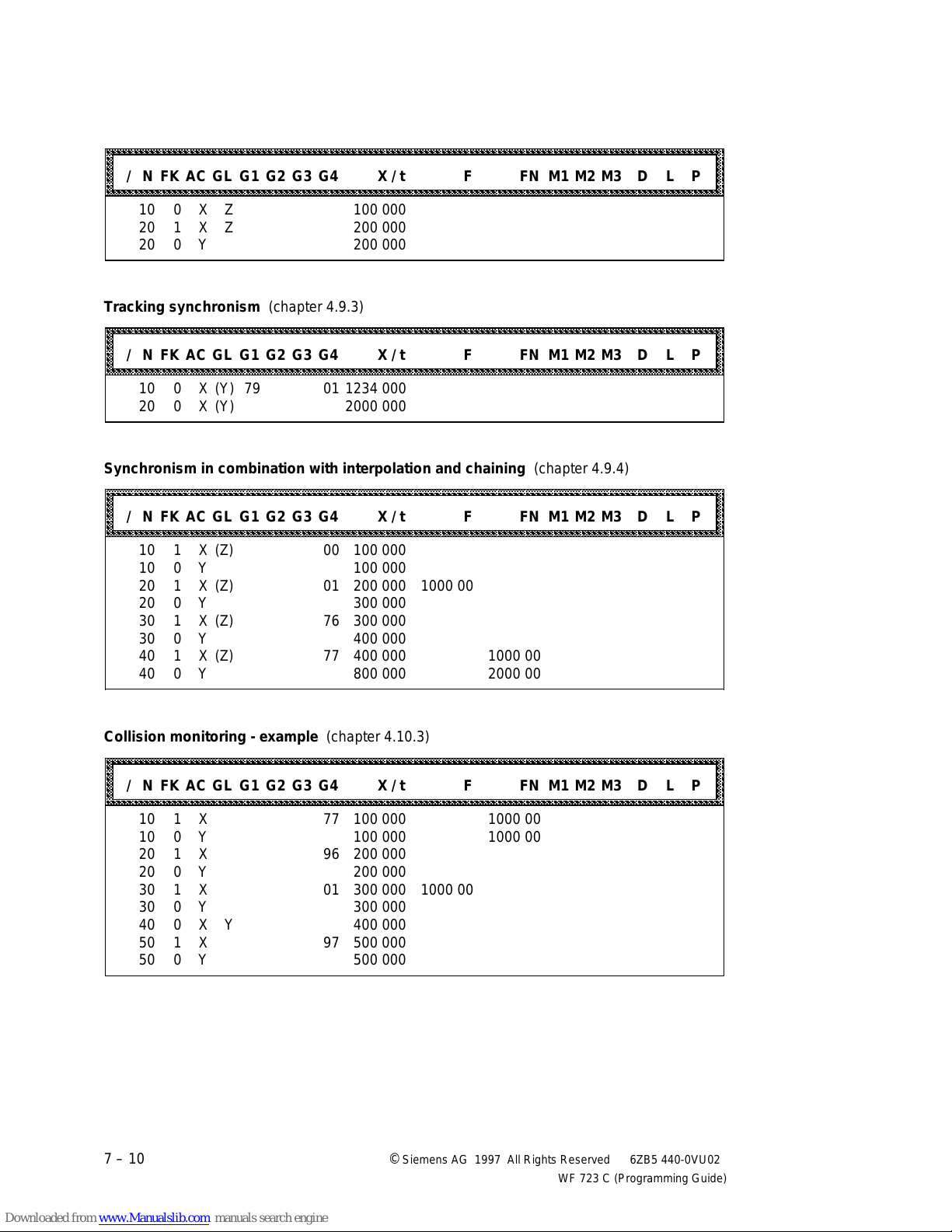
Programming in S5 Format 04.97
aaaaaaaaaaaaaaaaaaaaaaaaaaaaaaaaaaaaaaaaaaaaaaaaaaaaaaaaaaaaaaaaaaaaaaaaaaaaaaaaaaaaaaaaaaaaaaaaaaaaaaaaaaaaaaa
a
a
a
a
a
a
a
a
a
a
a
a
a
a
a
aaaaaaaaaaaaaaaaaaaaaaaaaaaaaaaaaaaaaaaaaaaaaaaaaaaaaaaaaaaaaaaaaaaaaaaaaaaaaaaaaaaaaaaaaaaaaaaaaaaaaaaaaaaaaaa
a
a
a
a
a
a
a
a
a
a
a
a
a
a
a
aaaaaaaaaaaaaaaaaaaaaaaaaaaaaaaaaaaaaaaaaaaaaaaaaaaaaaaaaaaaaaaaaaaaaaaaaaaaaaaaaaaaaaaaaaaaaaaaaaaaaaaaaaaaaaa
a
a
a
a
a
a
a
a
a
a
a
a
a
a
a
aaaaaaaaaaaaaaaaaaaaaaaaaaaaaaaaaaaaaaaaaaaaaaaaaaaaaaaaaaaaaaaaaaaaaaaaaaaaaaaaaaaaaaaaaaaaaaaaaaaaaaaaaaaaaaa
a
a
a
a
a
a
a
a
a
a
a
a
a
a
a
Selectable synchronism (chapter 4.9.2)
aaaaaaaaaaaaaaaaaaaaaaaaaaaaaaaaaaaaaaaaaaaaaaaaaaaaaaaaaaaaaaaaaaaaaaaaaaaaaaaaaaaaaaaaaaaaaaaaaaaaaaaaaaaaa
aaaaaaaaaaaaaaaaaaaaaaaaaaaaaaaaaaaaaaaaaaaaaaaaaaaaaaaaaaaaaaaaaaaaaaaaaaaaaaaaaaaaaaaaaaaaaaaaaaaaaaaaaaaaa
aaaaaaaaaaaaaaaaaaaaaaaaaaaaaaaaaaaaaaaaaaaaaaaaaaaaaaaaaaaaaaaaaaaaaaaaaaaaaaaaaaaaaaaaaaaaaaaaaaaaaaaaaaaaa
aaaaaaaaaaaaaaaaaaaaaaaaaaaaaaaaaaaaaaaaaaaaaaaaaaaaaaaaaaaaaaaaaaaaaaaaaaaaaaaaaaaaaaaaaaaaaaaaaaaaaaaaaaaaa
aaaaaaaaaaaaaaaaaaaaaaaaaaaaaaaaaaaaaaaaaaaaaaaaaaaaaaaaaaaaaaaaaaaaaaaaaaaaaaaaaaaaaaaaaaaaaaaaaaaaaaaaaaaaa
/ N FK AC GL G1 G2 G3 G4 X / t F FN M1 M2 M3 D L P
aaaaaaaaaaaaaaaaaaaaaaaaaaaaaaaaaaaaaaaaaaaaaaaaaaaaaaaaaaaaaaaaaaaaaaaaaaaaaaaaaaaaaaaaaaaaaaaaaaaaaaaaaaaaa
aaaaaaaaaaaaaaaaaaaaaaaaaaaaaaaaaaaaaaaaaaaaaaaaaaaaaaaaaaaaaaaaaaaaaaaaaaaaaaaaaaaaaaaaaaaaaaaaaaaaaaaaaaaaa
10 0 X Z 100 000
20 1 X Z 200 000
20 0 Y 200 000
Tracking synchronism (chapter 4.9.3)
aaaaaaaaaaaaaaaaaaaaaaaaaaaaaaaaaaaaaaaaaaaaaaaaaaaaaaaaaaaaaaaaaaaaaaaaaaaaaaaaaaaaaaaaaaaaaaaaaaaaaaaaaaaaa
aaaaaaaaaaaaaaaaaaaaaaaaaaaaaaaaaaaaaaaaaaaaaaaaaaaaaaaaaaaaaaaaaaaaaaaaaaaaaaaaaaaaaaaaaaaaaaaaaaaaaaaaaaaaa
aaaaaaaaaaaaaaaaaaaaaaaaaaaaaaaaaaaaaaaaaaaaaaaaaaaaaaaaaaaaaaaaaaaaaaaaaaaaaaaaaaaaaaaaaaaaaaaaaaaaaaaaaaaaa
aaaaaaaaaaaaaaaaaaaaaaaaaaaaaaaaaaaaaaaaaaaaaaaaaaaaaaaaaaaaaaaaaaaaaaaaaaaaaaaaaaaaaaaaaaaaaaaaaaaaaaaaaaaaa
aaaaaaaaaaaaaaaaaaaaaaaaaaaaaaaaaaaaaaaaaaaaaaaaaaaaaaaaaaaaaaaaaaaaaaaaaaaaaaaaaaaaaaaaaaaaaaaaaaaaaaaaaaaaa
/ N FK AC GL G1 G2 G3 G4 X / t F FN M1 M2 M3 D L P
aaaaaaaaaaaaaaaaaaaaaaaaaaaaaaaaaaaaaaaaaaaaaaaaaaaaaaaaaaaaaaaaaaaaaaaaaaaaaaaaaaaaaaaaaaaaaaaaaaaaaaaaaaaaa
aaaaaaaaaaaaaaaaaaaaaaaaaaaaaaaaaaaaaaaaaaaaaaaaaaaaaaaaaaaaaaaaaaaaaaaaaaaaaaaaaaaaaaaaaaaaaaaaaaaaaaaaaaaaa
10 0 X (Y) 79 01 1234 000
20 0 X (Y) 2000 000
Synchronism in combination with interpolation and chaining (chapter 4.9.4)
aaaaaaaaaaaaaaaaaaaaaaaaaaaaaaaaaaaaaaaaaaaaaaaaaaaaaaaaaaaaaaaaaaaaaaaaaaaaaaaaaaaaaaaaaaaaaaaaaaaaaaaaaaaaa
aaaaaaaaaaaaaaaaaaaaaaaaaaaaaaaaaaaaaaaaaaaaaaaaaaaaaaaaaaaaaaaaaaaaaaaaaaaaaaaaaaaaaaaaaaaaaaaaaaaaaaaaaaaaa
aaaaaaaaaaaaaaaaaaaaaaaaaaaaaaaaaaaaaaaaaaaaaaaaaaaaaaaaaaaaaaaaaaaaaaaaaaaaaaaaaaaaaaaaaaaaaaaaaaaaaaaaaaaaa
aaaaaaaaaaaaaaaaaaaaaaaaaaaaaaaaaaaaaaaaaaaaaaaaaaaaaaaaaaaaaaaaaaaaaaaaaaaaaaaaaaaaaaaaaaaaaaaaaaaaaaaaaaaaa
aaaaaaaaaaaaaaaaaaaaaaaaaaaaaaaaaaaaaaaaaaaaaaaaaaaaaaaaaaaaaaaaaaaaaaaaaaaaaaaaaaaaaaaaaaaaaaaaaaaaaaaaaaaaa
/ N FK AC GL G1 G2 G3 G4 X / t F FN M1 M2 M3 D L P
aaaaaaaaaaaaaaaaaaaaaaaaaaaaaaaaaaaaaaaaaaaaaaaaaaaaaaaaaaaaaaaaaaaaaaaaaaaaaaaaaaaaaaaaaaaaaaaaaaaaaaaaaaaaa
aaaaaaaaaaaaaaaaaaaaaaaaaaaaaaaaaaaaaaaaaaaaaaaaaaaaaaaaaaaaaaaaaaaaaaaaaaaaaaaaaaaaaaaaaaaaaaaaaaaaaaaaaaaaa
10 1 X (Z) 00 100 000
10 0 Y 100 000
20 1 X (Z) 01 200 000 1000 00
20 0 Y 300 000
30 1 X (Z) 76 300 000
30 0 Y 400 000
40 1 X (Z) 77 400 000 1000 00
40 0 Y 800 000 2000 00
a
a
a
a
a
a
a
a
a
a
a
a
a
a
a
a
a
a
a
a
a
Collision monitoring - example (chapter 4.10.3)
aaaaaaaaaaaaaaaaaaaaaaaaaaaaaaaaaaaaaaaaaaaaaaaaaaaaaaaaaaaaaaaaaaaaaaaaaaaaaaaaaaaaaaaaaaaaaaaaaaaaaaaaaaaaa
aaaaaaaaaaaaaaaaaaaaaaaaaaaaaaaaaaaaaaaaaaaaaaaaaaaaaaaaaaaaaaaaaaaaaaaaaaaaaaaaaaaaaaaaaaaaaaaaaaaaaaaaaaaaa
aaaaaaaaaaaaaaaaaaaaaaaaaaaaaaaaaaaaaaaaaaaaaaaaaaaaaaaaaaaaaaaaaaaaaaaaaaaaaaaaaaaaaaaaaaaaaaaaaaaaaaaaaaaaa
aaaaaaaaaaaaaaaaaaaaaaaaaaaaaaaaaaaaaaaaaaaaaaaaaaaaaaaaaaaaaaaaaaaaaaaaaaaaaaaaaaaaaaaaaaaaaaaaaaaaaaaaaaaaa
aaaaaaaaaaaaaaaaaaaaaaaaaaaaaaaaaaaaaaaaaaaaaaaaaaaaaaaaaaaaaaaaaaaaaaaaaaaaaaaaaaaaaaaaaaaaaaaaaaaaaaaaaaaaa
/ N FK AC GL G1 G2 G3 G4 X / t F FN M1 M2 M3 D L P
aaaaaaaaaaaaaaaaaaaaaaaaaaaaaaaaaaaaaaaaaaaaaaaaaaaaaaaaaaaaaaaaaaaaaaaaaaaaaaaaaaaaaaaaaaaaaaaaaaaaaaaaaaaaa
aaaaaaaaaaaaaaaaaaaaaaaaaaaaaaaaaaaaaaaaaaaaaaaaaaaaaaaaaaaaaaaaaaaaaaaaaaaaaaaaaaaaaaaaaaaaaaaaaaaaaaaaaaaaa
10 1 X 77 100 000 1000 00
10 0 Y 100 000 1000 00
20 1 X 96 200 000
20 0 Y 200 000
30 1 X 01 300 000 1000 00
30 0 Y 300 000
40 0 X Y 400 000
50 1 X 97 500 000
50 0 Y 500 000
7 – 10 ©
Siemens AG 1997 All Rights Reserved 6ZB5 440-0VU02
WF 723 C (Programming Guide)
a
a
a
a
a
a
a
Page 86
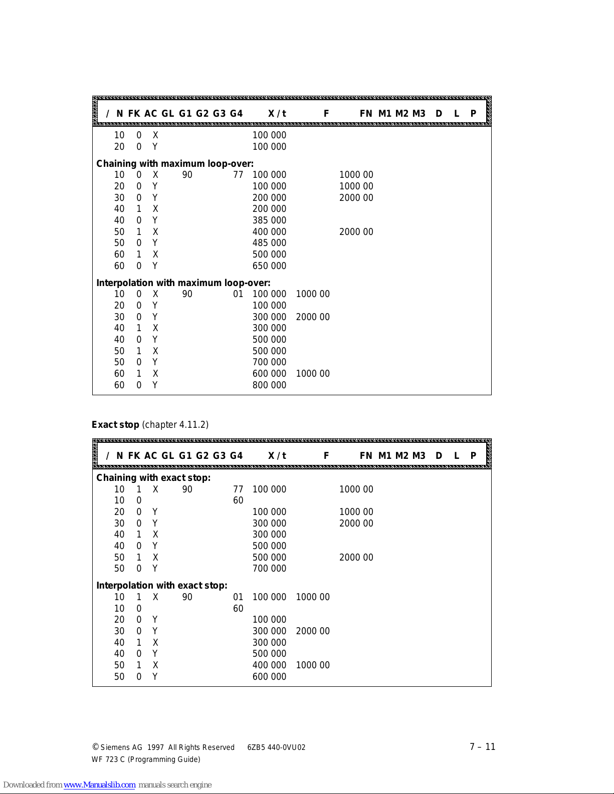
04.97 Programming in S5 Format
aaaaaaaaaaaaaaaaaaaaaaaaaaaaaaaaaaaaaaaaaaaaaaaaaaaaaaaaaaaaaaaaaaaaaaaaaaaaaaaaaaaaaaaaaaaaaaaaaaaaaaaaaaaaaaa
a
a
a
a
a
a
a
a
a
a
a
a
a
a
a
aaaaaaaaaaaaaaaaaaaaaaaaaaaaaaaaaaaaaaaaaaaaaaaaaaaaaaaaaaaaaaaaaaaaaaaaaaaaaaaaaaaaaaaaaaaaaaaaaaaaaaaaaaaaaaa
a
a
a
a
a
a
a
a
a
a
a
a
a
a
a
Maximum loop-over (chapter 4.11.1)
aaaaaaaaaaaaaaaaaaaaaaaaaaaaaaaaaaaaaaaaaaaaaaaaaaaaaaaaaaaaaaaaaaaaaaaaaaaaaaaaaaaaaaaaaaaaaaaaaaaaaaaaaaaaa
aaaaaaaaaaaaaaaaaaaaaaaaaaaaaaaaaaaaaaaaaaaaaaaaaaaaaaaaaaaaaaaaaaaaaaaaaaaaaaaaaaaaaaaaaaaaaaaaaaaaaaaaaaaaa
aaaaaaaaaaaaaaaaaaaaaaaaaaaaaaaaaaaaaaaaaaaaaaaaaaaaaaaaaaaaaaaaaaaaaaaaaaaaaaaaaaaaaaaaaaaaaaaaaaaaaaaaaaaaa
aaaaaaaaaaaaaaaaaaaaaaaaaaaaaaaaaaaaaaaaaaaaaaaaaaaaaaaaaaaaaaaaaaaaaaaaaaaaaaaaaaaaaaaaaaaaaaaaaaaaaaaaaaaaa
aaaaaaaaaaaaaaaaaaaaaaaaaaaaaaaaaaaaaaaaaaaaaaaaaaaaaaaaaaaaaaaaaaaaaaaaaaaaaaaaaaaaaaaaaaaaaaaaaaaaaaaaaaaaa
/ N FK AC GL G1 G2 G3 G4 X / t F FN M1 M2 M3 D L P
aaaaaaaaaaaaaaaaaaaaaaaaaaaaaaaaaaaaaaaaaaaaaaaaaaaaaaaaaaaaaaaaaaaaaaaaaaaaaaaaaaaaaaaaaaaaaaaaaaaaaaaaaaaaa
aaaaaaaaaaaaaaaaaaaaaaaaaaaaaaaaaaaaaaaaaaaaaaaaaaaaaaaaaaaaaaaaaaaaaaaaaaaaaaaaaaaaaaaaaaaaaaaaaaaaaaaaaaaaa
10 0 X 100 000
20 0 Y 100 000
Chaining with maximum loop-over:
10 0 X 90 77 100 000 1000 00
20 0 Y 100 000 1000 00
30 0 Y 200 000 2000 00
40 1 X 200 000
40 0 Y 385 000
50 1 X 400 000 2000 00
50 0 Y 485 000
60 1 X 500 000
60 0 Y 650 000
Interpolation with maximum loop-over:
10 0 X 90 01 100 000 1000 00
20 0 Y 100 000
30 0 Y 300 000 2000 00
40 1 X 300 000
40 0 Y 500 000
50 1 X 500 000
50 0 Y 700 000
60 1 X 600 000 1000 00
60 0 Y 800 000
a
a
a
a
a
a
a
Exact stop (chapter 4.11.2)
aaaaaaaaaaaaaaaaaaaaaaaaaaaaaaaaaaaaaaaaaaaaaaaaaaaaaaaaaaaaaaaaaaaaaaaaaaaaaaaaaaaaaaaaaaaaaaaaaaaaaaaaaaaaa
aaaaaaaaaaaaaaaaaaaaaaaaaaaaaaaaaaaaaaaaaaaaaaaaaaaaaaaaaaaaaaaaaaaaaaaaaaaaaaaaaaaaaaaaaaaaaaaaaaaaaaaaaaaaa
aaaaaaaaaaaaaaaaaaaaaaaaaaaaaaaaaaaaaaaaaaaaaaaaaaaaaaaaaaaaaaaaaaaaaaaaaaaaaaaaaaaaaaaaaaaaaaaaaaaaaaaaaaaaa
aaaaaaaaaaaaaaaaaaaaaaaaaaaaaaaaaaaaaaaaaaaaaaaaaaaaaaaaaaaaaaaaaaaaaaaaaaaaaaaaaaaaaaaaaaaaaaaaaaaaaaaaaaaaa
aaaaaaaaaaaaaaaaaaaaaaaaaaaaaaaaaaaaaaaaaaaaaaaaaaaaaaaaaaaaaaaaaaaaaaaaaaaaaaaaaaaaaaaaaaaaaaaaaaaaaaaaaaaaa
/ N FK AC GL G1 G2 G3 G4 X / t F FN M1 M2 M3 D L P
aaaaaaaaaaaaaaaaaaaaaaaaaaaaaaaaaaaaaaaaaaaaaaaaaaaaaaaaaaaaaaaaaaaaaaaaaaaaaaaaaaaaaaaaaaaaaaaaaaaaaaaaaaaaa
aaaaaaaaaaaaaaaaaaaaaaaaaaaaaaaaaaaaaaaaaaaaaaaaaaaaaaaaaaaaaaaaaaaaaaaaaaaaaaaaaaaaaaaaaaaaaaaaaaaaaaaaaaaaa
Chaining with exact stop:
10 1 X 90 77 100 000 1000 00
10 0 60
20 0 Y 100 000 1000 00
30 0 Y 300 000 2000 00
40 1 X 300 000
40 0 Y 500 000
50 1 X 500 000 2000 00
50 0 Y 700 000
Interpolation with exact stop:
10 1 X 90 01 100 000 1000 00
10 0 60
20 0 Y 100 000
30 0 Y 300 000 2000 00
40 1 X 300 000
40 0 Y 500 000
50 1 X 400 000 1000 00
50 0 Y 600 000
a
a
a
a
a
a
a
©
Siemens AG 1997 All Rights Reserved 6ZB5 440-0VU02
WF 723 C (Programming Guide)
7 – 11
Page 87
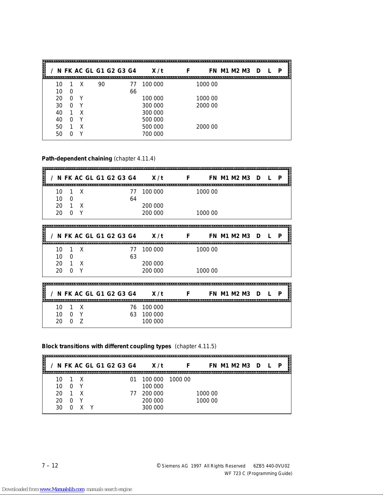
Programming in S5 Format 04.97
aaaaaaaaaaaaaaaaaaaaaaaaaaaaaaaaaaaaaaaaaaaaaaaaaaaaaaaaaaaaaaaaaaaaaaaaaaaaaaaaaaaaaaaaaaaaaaaaaaaaaaaaaaaaaaa
a
a
a
a
a
a
a
a
a
a
a
a
a
a
a
aaaaaaaaaaaaaaaaaaaaaaaaaaaaaaaaaaaaaaaaaaaaaaaaaaaaaaaaaaaaaaaaaaaaaaaaaaaaaaaaaaaaaaaaaaaaaaaaaaaaaaaaaaaaaaa
a
a
a
a
a
a
a
a
a
a
a
a
a
a
a
aaaaaaaaaaaaaaaaaaaaaaaaaaaaaaaaaaaaaaaaaaaaaaaaaaaaaaaaaaaaaaaaaaaaaaaaaaaaaaaaaaaaaaaaaaaaaaaaaaaaaaaaaaaaaaa
a
a
a
a
a
a
a
a
a
a
a
a
a
a
a
aaaaaaaaaaaaaaaaaaaaaaaaaaaaaaaaaaaaaaaaaaaaaaaaaaaaaaaaaaaaaaaaaaaaaaaaaaaaaaaaaaaaaaaaaaaaaaaaaaaaaaaaaaaaaaa
a
a
a
a
a
a
a
a
a
a
a
a
a
a
a
a
a
aaaaaaaaaaaaaaaaaaaaaaaaaaaaaaaaaaaaaaaaaaaaaaaaaaaaaaaaaaaaaaaaaaaaaaaaaaaaaaaaaaaaaaaaaaaaaaaaaaaaaaaaaaaaaaa
a
a
a
a
a
a
a
a
a
a
a
a
a
a
a
a
a
Loop-over window 1 or 2 (chapter 4.11.3)
aaaaaaaaaaaaaaaaaaaaaaaaaaaaaaaaaaaaaaaaaaaaaaaaaaaaaaaaaaaaaaaaaaaaaaaaaaaaaaaaaaaaaaaaaaaaaaaaaaaaaaaaaaaaa
aaaaaaaaaaaaaaaaaaaaaaaaaaaaaaaaaaaaaaaaaaaaaaaaaaaaaaaaaaaaaaaaaaaaaaaaaaaaaaaaaaaaaaaaaaaaaaaaaaaaaaaaaaaaa
aaaaaaaaaaaaaaaaaaaaaaaaaaaaaaaaaaaaaaaaaaaaaaaaaaaaaaaaaaaaaaaaaaaaaaaaaaaaaaaaaaaaaaaaaaaaaaaaaaaaaaaaaaaaa
aaaaaaaaaaaaaaaaaaaaaaaaaaaaaaaaaaaaaaaaaaaaaaaaaaaaaaaaaaaaaaaaaaaaaaaaaaaaaaaaaaaaaaaaaaaaaaaaaaaaaaaaaaaaa
aaaaaaaaaaaaaaaaaaaaaaaaaaaaaaaaaaaaaaaaaaaaaaaaaaaaaaaaaaaaaaaaaaaaaaaaaaaaaaaaaaaaaaaaaaaaaaaaaaaaaaaaaaaaa
/ N FK AC GL G1 G2 G3 G4 X / t F FN M1 M2 M3 D L P
aaaaaaaaaaaaaaaaaaaaaaaaaaaaaaaaaaaaaaaaaaaaaaaaaaaaaaaaaaaaaaaaaaaaaaaaaaaaaaaaaaaaaaaaaaaaaaaaaaaaaaaaaaaaa
aaaaaaaaaaaaaaaaaaaaaaaaaaaaaaaaaaaaaaaaaaaaaaaaaaaaaaaaaaaaaaaaaaaaaaaaaaaaaaaaaaaaaaaaaaaaaaaaaaaaaaaaaaaaa
10 1 X 90 77 100 000 1000 00
10 0 66
20 0 Y 100 000 1000 00
30 0 Y 300 000 2000 00
40 1 X 300 000
40 0 Y 500 000
50 1 X 500 000 2000 00
50 0 Y 700 000
Path-dependent chaining (chapter 4.11.4)
aaaaaaaaaaaaaaaaaaaaaaaaaaaaaaaaaaaaaaaaaaaaaaaaaaaaaaaaaaaaaaaaaaaaaaaaaaaaaaaaaaaaaaaaaaaaaaaaaaaaaaaaaaaaa
aaaaaaaaaaaaaaaaaaaaaaaaaaaaaaaaaaaaaaaaaaaaaaaaaaaaaaaaaaaaaaaaaaaaaaaaaaaaaaaaaaaaaaaaaaaaaaaaaaaaaaaaaaaaa
aaaaaaaaaaaaaaaaaaaaaaaaaaaaaaaaaaaaaaaaaaaaaaaaaaaaaaaaaaaaaaaaaaaaaaaaaaaaaaaaaaaaaaaaaaaaaaaaaaaaaaaaaaaaa
aaaaaaaaaaaaaaaaaaaaaaaaaaaaaaaaaaaaaaaaaaaaaaaaaaaaaaaaaaaaaaaaaaaaaaaaaaaaaaaaaaaaaaaaaaaaaaaaaaaaaaaaaaaaa
aaaaaaaaaaaaaaaaaaaaaaaaaaaaaaaaaaaaaaaaaaaaaaaaaaaaaaaaaaaaaaaaaaaaaaaaaaaaaaaaaaaaaaaaaaaaaaaaaaaaaaaaaaaaa
/ N FK AC GL G1 G2 G3 G4 X / t F FN M1 M2 M3 D L P
aaaaaaaaaaaaaaaaaaaaaaaaaaaaaaaaaaaaaaaaaaaaaaaaaaaaaaaaaaaaaaaaaaaaaaaaaaaaaaaaaaaaaaaaaaaaaaaaaaaaaaaaaaaaa
aaaaaaaaaaaaaaaaaaaaaaaaaaaaaaaaaaaaaaaaaaaaaaaaaaaaaaaaaaaaaaaaaaaaaaaaaaaaaaaaaaaaaaaaaaaaaaaaaaaaaaaaaaaaa
10 1 X 77 100 000 1000 00
10 0 64
20 1 X 200 000
20 0 Y 200 000 1000 00
a
a
a
a
a
a
a
a
a
a
a
a
a
a
aaaaaaaaaaaaaaaaaaaaaaaaaaaaaaaaaaaaaaaaaaaaaaaaaaaaaaaaaaaaaaaaaaaaaaaaaaaaaaaaaaaaaaaaaaaaaaaaaaaaaaaaaaaaa
aaaaaaaaaaaaaaaaaaaaaaaaaaaaaaaaaaaaaaaaaaaaaaaaaaaaaaaaaaaaaaaaaaaaaaaaaaaaaaaaaaaaaaaaaaaaaaaaaaaaaaaaaaaaa
aaaaaaaaaaaaaaaaaaaaaaaaaaaaaaaaaaaaaaaaaaaaaaaaaaaaaaaaaaaaaaaaaaaaaaaaaaaaaaaaaaaaaaaaaaaaaaaaaaaaaaaaaaaaa
aaaaaaaaaaaaaaaaaaaaaaaaaaaaaaaaaaaaaaaaaaaaaaaaaaaaaaaaaaaaaaaaaaaaaaaaaaaaaaaaaaaaaaaaaaaaaaaaaaaaaaaaaaaaa
/ N FK AC GL G1 G2 G3 G4 X / t F FN M1 M2 M3 D L P
aaaaaaaaaaaaaaaaaaaaaaaaaaaaaaaaaaaaaaaaaaaaaaaaaaaaaaaaaaaaaaaaaaaaaaaaaaaaaaaaaaaaaaaaaaaaaaaaaaaaaaaaaaaaa
aaaaaaaaaaaaaaaaaaaaaaaaaaaaaaaaaaaaaaaaaaaaaaaaaaaaaaaaaaaaaaaaaaaaaaaaaaaaaaaaaaaaaaaaaaaaaaaaaaaaaaaaaaaaa
aaaaaaaaaaaaaaaaaaaaaaaaaaaaaaaaaaaaaaaaaaaaaaaaaaaaaaaaaaaaaaaaaaaaaaaaaaaaaaaaaaaaaaaaaaaaaaaaaaaaaaaaaaaaa
10 1 X 77 100 000 1000 00
10 0 63
20 1 X 200 000
20 0 Y 200 000 1000 00
aaaaaaaaaaaaaaaaaaaaaaaaaaaaaaaaaaaaaaaaaaaaaaaaaaaaaaaaaaaaaaaaaaaaaaaaaaaaaaaaaaaaaaaaaaaaaaaaaaaaaaaaaaaaa
aaaaaaaaaaaaaaaaaaaaaaaaaaaaaaaaaaaaaaaaaaaaaaaaaaaaaaaaaaaaaaaaaaaaaaaaaaaaaaaaaaaaaaaaaaaaaaaaaaaaaaaaaaaaa
aaaaaaaaaaaaaaaaaaaaaaaaaaaaaaaaaaaaaaaaaaaaaaaaaaaaaaaaaaaaaaaaaaaaaaaaaaaaaaaaaaaaaaaaaaaaaaaaaaaaaaaaaaaaa
aaaaaaaaaaaaaaaaaaaaaaaaaaaaaaaaaaaaaaaaaaaaaaaaaaaaaaaaaaaaaaaaaaaaaaaaaaaaaaaaaaaaaaaaaaaaaaaaaaaaaaaaaaaaa
aaaaaaaaaaaaaaaaaaaaaaaaaaaaaaaaaaaaaaaaaaaaaaaaaaaaaaaaaaaaaaaaaaaaaaaaaaaaaaaaaaaaaaaaaaaaaaaaaaaaaaaaaaaaa
/ N FK AC GL G1 G2 G3 G4 X / t F FN M1 M2 M3 D L P
aaaaaaaaaaaaaaaaaaaaaaaaaaaaaaaaaaaaaaaaaaaaaaaaaaaaaaaaaaaaaaaaaaaaaaaaaaaaaaaaaaaaaaaaaaaaaaaaaaaaaaaaaaaaa
aaaaaaaaaaaaaaaaaaaaaaaaaaaaaaaaaaaaaaaaaaaaaaaaaaaaaaaaaaaaaaaaaaaaaaaaaaaaaaaaaaaaaaaaaaaaaaaaaaaaaaaaaaaaa
aaaaaaaaaaaaaaaaaaaaaaaaaaaaaaaaaaaaaaaaaaaaaaaaaaaaaaaaaaaaaaaaaaaaaaaaaaaaaaaaaaaaaaaaaaaaaaaaaaaaaaaaaaaaa
10 1 X 76 100 000
10 0 Y 63 100 000
20 0 Z 100 000
Block transitions with different coupling types (chapter 4.11.5)
aaaaaaaaaaaaaaaaaaaaaaaaaaaaaaaaaaaaaaaaaaaaaaaaaaaaaaaaaaaaaaaaaaaaaaaaaaaaaaaaaaaaaaaaaaaaaaaaaaaaaaaaaaaaa
aaaaaaaaaaaaaaaaaaaaaaaaaaaaaaaaaaaaaaaaaaaaaaaaaaaaaaaaaaaaaaaaaaaaaaaaaaaaaaaaaaaaaaaaaaaaaaaaaaaaaaaaaaaaa
aaaaaaaaaaaaaaaaaaaaaaaaaaaaaaaaaaaaaaaaaaaaaaaaaaaaaaaaaaaaaaaaaaaaaaaaaaaaaaaaaaaaaaaaaaaaaaaaaaaaaaaaaaaaa
aaaaaaaaaaaaaaaaaaaaaaaaaaaaaaaaaaaaaaaaaaaaaaaaaaaaaaaaaaaaaaaaaaaaaaaaaaaaaaaaaaaaaaaaaaaaaaaaaaaaaaaaaaaaa
aaaaaaaaaaaaaaaaaaaaaaaaaaaaaaaaaaaaaaaaaaaaaaaaaaaaaaaaaaaaaaaaaaaaaaaaaaaaaaaaaaaaaaaaaaaaaaaaaaaaaaaaaaaaa
/ N FK AC GL G1 G2 G3 G4 X / t F FN M1 M2 M3 D L P
aaaaaaaaaaaaaaaaaaaaaaaaaaaaaaaaaaaaaaaaaaaaaaaaaaaaaaaaaaaaaaaaaaaaaaaaaaaaaaaaaaaaaaaaaaaaaaaaaaaaaaaaaaaaa
aaaaaaaaaaaaaaaaaaaaaaaaaaaaaaaaaaaaaaaaaaaaaaaaaaaaaaaaaaaaaaaaaaaaaaaaaaaaaaaaaaaaaaaaaaaaaaaaaaaaaaaaaaaaa
aaaaaaaaaaaaaaaaaaaaaaaaaaaaaaaaaaaaaaaaaaaaaaaaaaaaaaaaaaaaaaaaaaaaaaaaaaaaaaaaaaaaaaaaaaaaaaaaaaaaaaaaaaaaa
10 1 X 01 100 000 1000 00
10 0 Y 100 000
20 1 X 77 200 000 1000 00
20 0 Y 200 000 1000 00
30 0 X Y 300 000
a
a
a
a
a
a
a
a
a
a
a
a
a
a
a
a
a
a
a
a
a
a
a
7 – 12 ©
Siemens AG 1997 All Rights Reserved 6ZB5 440-0VU02
WF 723 C (Programming Guide)
Page 88
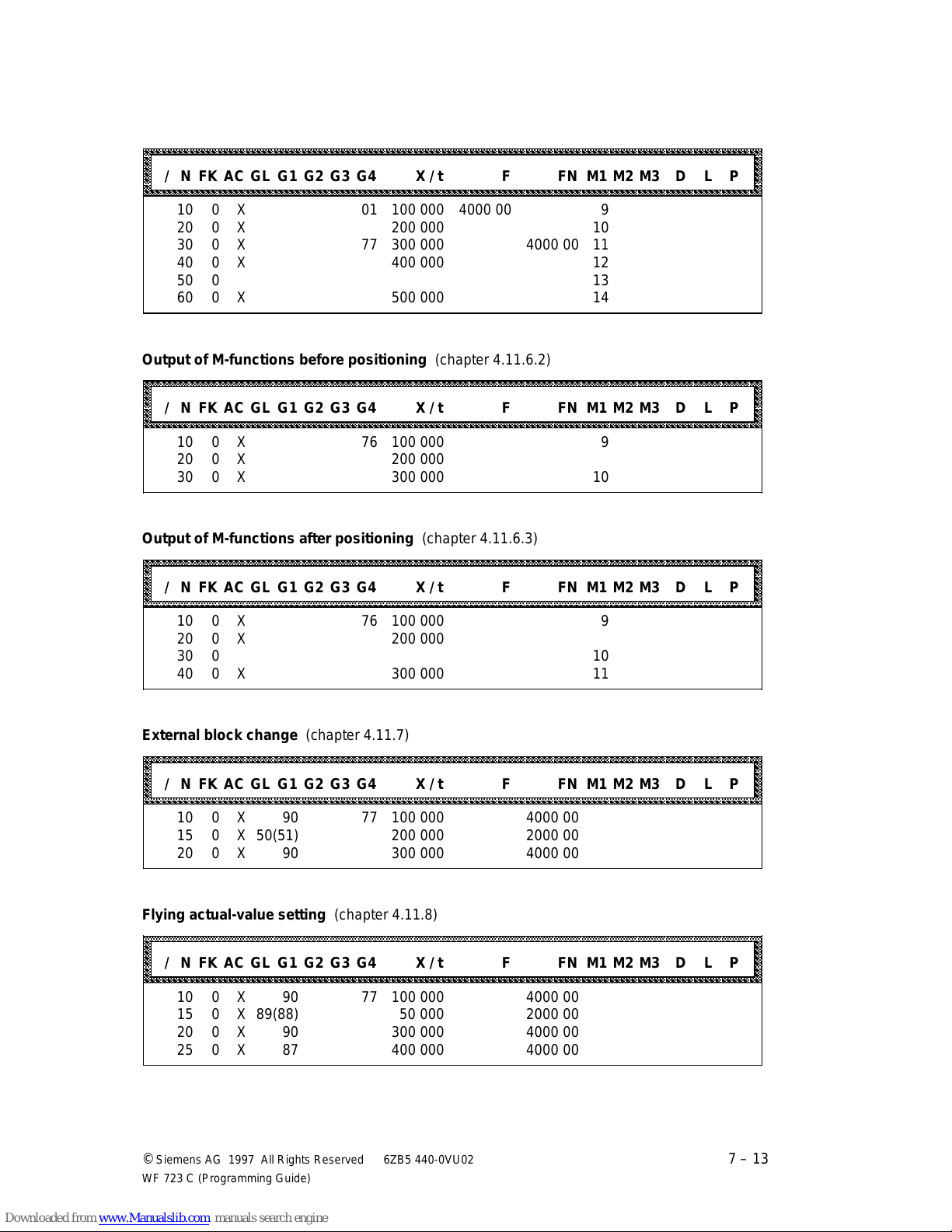
04.97 Programming in S5 Format
aaaaaaaaaaaaaaaaaaaaaaaaaaaaaaaaaaaaaaaaaaaaaaaaaaaaaaaaaaaaaaaaaaaaaaaaaaaaaaaaaaaaaaaaaaaaaaaaaaaaaaaaaaaaaaa
a
a
a
a
a
a
a
a
a
a
a
a
a
a
a
aaaaaaaaaaaaaaaaaaaaaaaaaaaaaaaaaaaaaaaaaaaaaaaaaaaaaaaaaaaaaaaaaaaaaaaaaaaaaaaaaaaaaaaaaaaaaaaaaaaaaaaaaaaaaaa
a
a
a
a
a
a
a
a
a
a
a
a
a
a
a
aaaaaaaaaaaaaaaaaaaaaaaaaaaaaaaaaaaaaaaaaaaaaaaaaaaaaaaaaaaaaaaaaaaaaaaaaaaaaaaaaaaaaaaaaaaaaaaaaaaaaaaaaaaaaaa
a
a
a
a
a
a
a
a
a
a
a
a
a
a
a
aaaaaaaaaaaaaaaaaaaaaaaaaaaaaaaaaaaaaaaaaaaaaaaaaaaaaaaaaaaaaaaaaaaaaaaaaaaaaaaaaaaaaaaaaaaaaaaaaaaaaaaaaaaaaaa
a
a
a
a
a
a
a
a
a
a
a
a
a
a
a
aaaaaaaaaaaaaaaaaaaaaaaaaaaaaaaaaaaaaaaaaaaaaaaaaaaaaaaaaaaaaaaaaaaaaaaaaaaaaaaaaaaaaaaaaaaaaaaaaaaaaaaaaaaaaaa
a
a
a
a
a
a
a
a
a
a
a
a
a
a
a
Output of M-functions during positioning (chapter 4.11.6.1)
aaaaaaaaaaaaaaaaaaaaaaaaaaaaaaaaaaaaaaaaaaaaaaaaaaaaaaaaaaaaaaaaaaaaaaaaaaaaaaaaaaaaaaaaaaaaaaaaaaaaaaaaaaaaa
aaaaaaaaaaaaaaaaaaaaaaaaaaaaaaaaaaaaaaaaaaaaaaaaaaaaaaaaaaaaaaaaaaaaaaaaaaaaaaaaaaaaaaaaaaaaaaaaaaaaaaaaaaaaa
aaaaaaaaaaaaaaaaaaaaaaaaaaaaaaaaaaaaaaaaaaaaaaaaaaaaaaaaaaaaaaaaaaaaaaaaaaaaaaaaaaaaaaaaaaaaaaaaaaaaaaaaaaaaa
aaaaaaaaaaaaaaaaaaaaaaaaaaaaaaaaaaaaaaaaaaaaaaaaaaaaaaaaaaaaaaaaaaaaaaaaaaaaaaaaaaaaaaaaaaaaaaaaaaaaaaaaaaaaa
aaaaaaaaaaaaaaaaaaaaaaaaaaaaaaaaaaaaaaaaaaaaaaaaaaaaaaaaaaaaaaaaaaaaaaaaaaaaaaaaaaaaaaaaaaaaaaaaaaaaaaaaaaaaa
/ N FK AC GL G1 G2 G3 G4 X / t F FN M1 M2 M3 D L P
aaaaaaaaaaaaaaaaaaaaaaaaaaaaaaaaaaaaaaaaaaaaaaaaaaaaaaaaaaaaaaaaaaaaaaaaaaaaaaaaaaaaaaaaaaaaaaaaaaaaaaaaaaaaa
aaaaaaaaaaaaaaaaaaaaaaaaaaaaaaaaaaaaaaaaaaaaaaaaaaaaaaaaaaaaaaaaaaaaaaaaaaaaaaaaaaaaaaaaaaaaaaaaaaaaaaaaaaaaa
10 0 X 01 100 000 4000 00 9
20 0 X 200 000 10
30 0 X 77 300 000 4000 00 11
40 0 X 400 000 12
50 0 13
60 0 X 500 000 14
Output of M-functions before positioning (chapter 4.11.6.2)
a
a
a
a
a
a
a
aaaaaaaaaaaaaaaaaaaaaaaaaaaaaaaaaaaaaaaaaaaaaaaaaaaaaaaaaaaaaaaaaaaaaaaaaaaaaaaaaaaaaaaaaaaaaaaaaaaaaaaaaaaaa
aaaaaaaaaaaaaaaaaaaaaaaaaaaaaaaaaaaaaaaaaaaaaaaaaaaaaaaaaaaaaaaaaaaaaaaaaaaaaaaaaaaaaaaaaaaaaaaaaaaaaaaaaaaaa
aaaaaaaaaaaaaaaaaaaaaaaaaaaaaaaaaaaaaaaaaaaaaaaaaaaaaaaaaaaaaaaaaaaaaaaaaaaaaaaaaaaaaaaaaaaaaaaaaaaaaaaaaaaaa
aaaaaaaaaaaaaaaaaaaaaaaaaaaaaaaaaaaaaaaaaaaaaaaaaaaaaaaaaaaaaaaaaaaaaaaaaaaaaaaaaaaaaaaaaaaaaaaaaaaaaaaaaaaaa
/ N FK AC GL G1 G2 G3 G4 X / t F FN M1 M2 M3 D L P
aaaaaaaaaaaaaaaaaaaaaaaaaaaaaaaaaaaaaaaaaaaaaaaaaaaaaaaaaaaaaaaaaaaaaaaaaaaaaaaaaaaaaaaaaaaaaaaaaaaaaaaaaaaaa
aaaaaaaaaaaaaaaaaaaaaaaaaaaaaaaaaaaaaaaaaaaaaaaaaaaaaaaaaaaaaaaaaaaaaaaaaaaaaaaaaaaaaaaaaaaaaaaaaaaaaaaaaaaaa
aaaaaaaaaaaaaaaaaaaaaaaaaaaaaaaaaaaaaaaaaaaaaaaaaaaaaaaaaaaaaaaaaaaaaaaaaaaaaaaaaaaaaaaaaaaaaaaaaaaaaaaaaaaaa
10 0 X 76 100 000 9
20 0 X 200 000
30 0 X 300 000 10
Output of M-functions after positioning (chapter 4.11.6.3)
aaaaaaaaaaaaaaaaaaaaaaaaaaaaaaaaaaaaaaaaaaaaaaaaaaaaaaaaaaaaaaaaaaaaaaaaaaaaaaaaaaaaaaaaaaaaaaaaaaaaaaaaaaaaa
aaaaaaaaaaaaaaaaaaaaaaaaaaaaaaaaaaaaaaaaaaaaaaaaaaaaaaaaaaaaaaaaaaaaaaaaaaaaaaaaaaaaaaaaaaaaaaaaaaaaaaaaaaaaa
aaaaaaaaaaaaaaaaaaaaaaaaaaaaaaaaaaaaaaaaaaaaaaaaaaaaaaaaaaaaaaaaaaaaaaaaaaaaaaaaaaaaaaaaaaaaaaaaaaaaaaaaaaaaa
aaaaaaaaaaaaaaaaaaaaaaaaaaaaaaaaaaaaaaaaaaaaaaaaaaaaaaaaaaaaaaaaaaaaaaaaaaaaaaaaaaaaaaaaaaaaaaaaaaaaaaaaaaaaa
/ N FK AC GL G1 G2 G3 G4 X / t F FN M1 M2 M3 D L P
aaaaaaaaaaaaaaaaaaaaaaaaaaaaaaaaaaaaaaaaaaaaaaaaaaaaaaaaaaaaaaaaaaaaaaaaaaaaaaaaaaaaaaaaaaaaaaaaaaaaaaaaaaaaa
aaaaaaaaaaaaaaaaaaaaaaaaaaaaaaaaaaaaaaaaaaaaaaaaaaaaaaaaaaaaaaaaaaaaaaaaaaaaaaaaaaaaaaaaaaaaaaaaaaaaaaaaaaaaa
aaaaaaaaaaaaaaaaaaaaaaaaaaaaaaaaaaaaaaaaaaaaaaaaaaaaaaaaaaaaaaaaaaaaaaaaaaaaaaaaaaaaaaaaaaaaaaaaaaaaaaaaaaaaa
10 0 X 76 100 000 9
20 0 X 200 000
30 0 10
40 0 X 300 000 11
External block change (chapter 4.11.7)
aaaaaaaaaaaaaaaaaaaaaaaaaaaaaaaaaaaaaaaaaaaaaaaaaaaaaaaaaaaaaaaaaaaaaaaaaaaaaaaaaaaaaaaaaaaaaaaaaaaaaaaaaaaaa
aaaaaaaaaaaaaaaaaaaaaaaaaaaaaaaaaaaaaaaaaaaaaaaaaaaaaaaaaaaaaaaaaaaaaaaaaaaaaaaaaaaaaaaaaaaaaaaaaaaaaaaaaaaaa
aaaaaaaaaaaaaaaaaaaaaaaaaaaaaaaaaaaaaaaaaaaaaaaaaaaaaaaaaaaaaaaaaaaaaaaaaaaaaaaaaaaaaaaaaaaaaaaaaaaaaaaaaaaaa
aaaaaaaaaaaaaaaaaaaaaaaaaaaaaaaaaaaaaaaaaaaaaaaaaaaaaaaaaaaaaaaaaaaaaaaaaaaaaaaaaaaaaaaaaaaaaaaaaaaaaaaaaaaaa
/ N FK AC GL G1 G2 G3 G4 X / t F FN M1 M2 M3 D L P
aaaaaaaaaaaaaaaaaaaaaaaaaaaaaaaaaaaaaaaaaaaaaaaaaaaaaaaaaaaaaaaaaaaaaaaaaaaaaaaaaaaaaaaaaaaaaaaaaaaaaaaaaaaaa
aaaaaaaaaaaaaaaaaaaaaaaaaaaaaaaaaaaaaaaaaaaaaaaaaaaaaaaaaaaaaaaaaaaaaaaaaaaaaaaaaaaaaaaaaaaaaaaaaaaaaaaaaaaaa
aaaaaaaaaaaaaaaaaaaaaaaaaaaaaaaaaaaaaaaaaaaaaaaaaaaaaaaaaaaaaaaaaaaaaaaaaaaaaaaaaaaaaaaaaaaaaaaaaaaaaaaaaaaaa
10 0 X 90 77 100 000 4000 00
15 0 X 50(51) 200 000 2000 00
20 0 X 90 300 000 4000 00
a
a
a
a
a
a
a
a
a
a
a
a
a
a
a
a
a
a
a
a
a
Flying actual-value setting (chapter 4.11.8)
aaaaaaaaaaaaaaaaaaaaaaaaaaaaaaaaaaaaaaaaaaaaaaaaaaaaaaaaaaaaaaaaaaaaaaaaaaaaaaaaaaaaaaaaaaaaaaaaaaaaaaaaaaaaa
aaaaaaaaaaaaaaaaaaaaaaaaaaaaaaaaaaaaaaaaaaaaaaaaaaaaaaaaaaaaaaaaaaaaaaaaaaaaaaaaaaaaaaaaaaaaaaaaaaaaaaaaaaaaa
aaaaaaaaaaaaaaaaaaaaaaaaaaaaaaaaaaaaaaaaaaaaaaaaaaaaaaaaaaaaaaaaaaaaaaaaaaaaaaaaaaaaaaaaaaaaaaaaaaaaaaaaaaaaa
aaaaaaaaaaaaaaaaaaaaaaaaaaaaaaaaaaaaaaaaaaaaaaaaaaaaaaaaaaaaaaaaaaaaaaaaaaaaaaaaaaaaaaaaaaaaaaaaaaaaaaaaaaaaa
/ N FK AC GL G1 G2 G3 G4 X / t F FN M1 M2 M3 D L P
aaaaaaaaaaaaaaaaaaaaaaaaaaaaaaaaaaaaaaaaaaaaaaaaaaaaaaaaaaaaaaaaaaaaaaaaaaaaaaaaaaaaaaaaaaaaaaaaaaaaaaaaaaaaa
aaaaaaaaaaaaaaaaaaaaaaaaaaaaaaaaaaaaaaaaaaaaaaaaaaaaaaaaaaaaaaaaaaaaaaaaaaaaaaaaaaaaaaaaaaaaaaaaaaaaaaaaaaaaa
aaaaaaaaaaaaaaaaaaaaaaaaaaaaaaaaaaaaaaaaaaaaaaaaaaaaaaaaaaaaaaaaaaaaaaaaaaaaaaaaaaaaaaaaaaaaaaaaaaaaaaaaaaaaa
10 0 X 90 77 100 000 4000 00
15 0 X 89(88) 50 000 2000 00
20 0 X 90 300 000 4000 00
25 0 X 87 400 000 4000 00
©
Siemens AG 1997 All Rights Reserved 6ZB5 440-0VU02
WF 723 C (Programming Guide)
a
a
a
a
a
a
a
7 – 13
Page 89
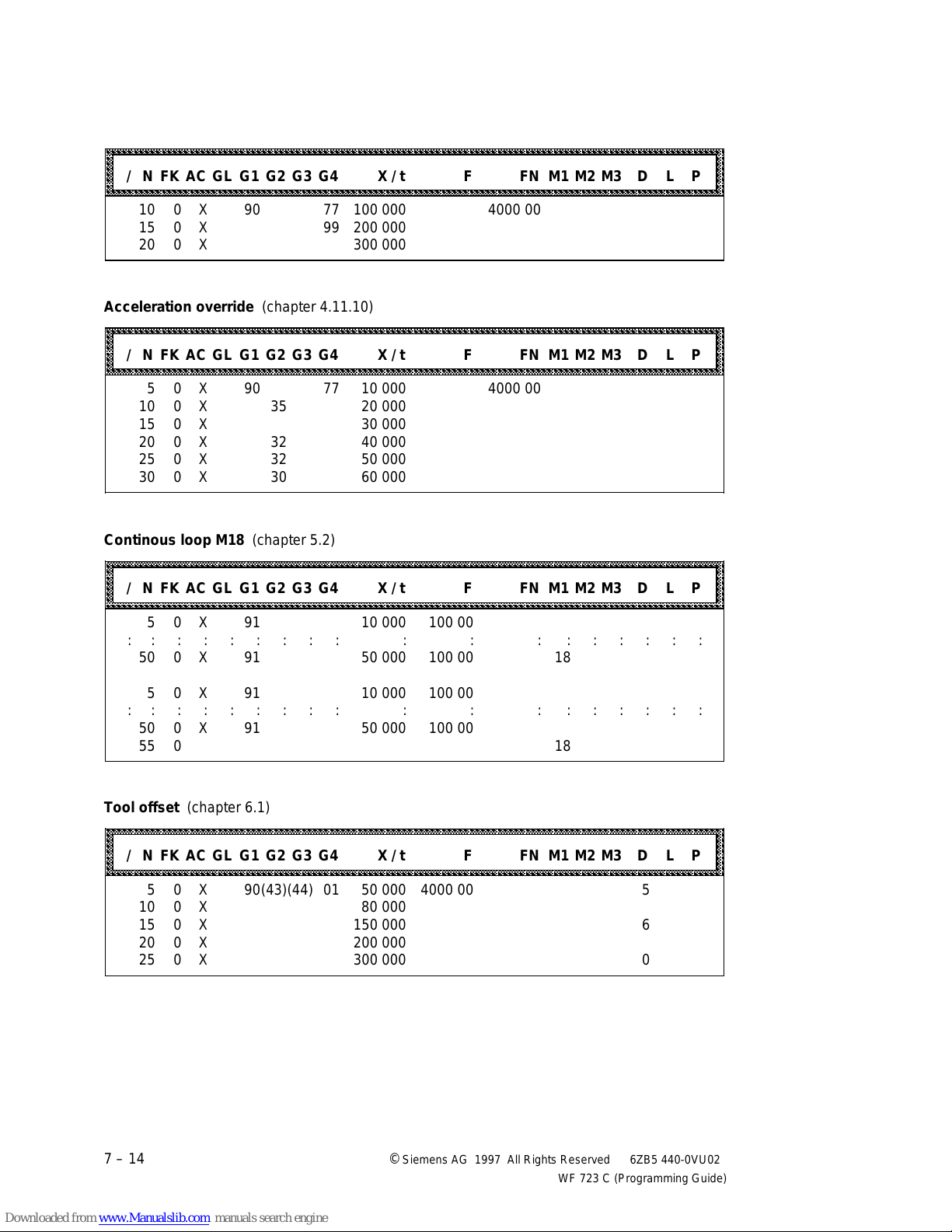
Programming in S5 Format 04.97
aaaaaaaaaaaaaaaaaaaaaaaaaaaaaaaaaaaaaaaaaaaaaaaaaaaaaaaaaaaaaaaaaaaaaaaaaaaaaaaaaaaaaaaaaaaaaaaaaaaaaaaaaaaaaaa
a
a
a
a
a
a
a
a
a
a
a
a
a
a
a
aaaaaaaaaaaaaaaaaaaaaaaaaaaaaaaaaaaaaaaaaaaaaaaaaaaaaaaaaaaaaaaaaaaaaaaaaaaaaaaaaaaaaaaaaaaaaaaaaaaaaaaaaaaaaaa
a
a
a
a
a
a
a
a
a
a
a
a
a
a
a
aaaaaaaaaaaaaaaaaaaaaaaaaaaaaaaaaaaaaaaaaaaaaaaaaaaaaaaaaaaaaaaaaaaaaaaaaaaaaaaaaaaaaaaaaaaaaaaaaaaaaaaaaaaaaaa
a
a
a
a
a
a
a
a
a
a
a
a
a
a
a
aaaaaaaaaaaaaaaaaaaaaaaaaaaaaaaaaaaaaaaaaaaaaaaaaaaaaaaaaaaaaaaaaaaaaaaaaaaaaaaaaaaaaaaaaaaaaaaaaaaaaaaaaaaaaaa
a
a
a
a
a
a
a
a
a
a
a
a
a
a
a
Program-dependent external read-in enable (chapter 4.11.9)
aaaaaaaaaaaaaaaaaaaaaaaaaaaaaaaaaaaaaaaaaaaaaaaaaaaaaaaaaaaaaaaaaaaaaaaaaaaaaaaaaaaaaaaaaaaaaaaaaaaaaaaaaaaaa
aaaaaaaaaaaaaaaaaaaaaaaaaaaaaaaaaaaaaaaaaaaaaaaaaaaaaaaaaaaaaaaaaaaaaaaaaaaaaaaaaaaaaaaaaaaaaaaaaaaaaaaaaaaaa
aaaaaaaaaaaaaaaaaaaaaaaaaaaaaaaaaaaaaaaaaaaaaaaaaaaaaaaaaaaaaaaaaaaaaaaaaaaaaaaaaaaaaaaaaaaaaaaaaaaaaaaaaaaaa
aaaaaaaaaaaaaaaaaaaaaaaaaaaaaaaaaaaaaaaaaaaaaaaaaaaaaaaaaaaaaaaaaaaaaaaaaaaaaaaaaaaaaaaaaaaaaaaaaaaaaaaaaaaaa
aaaaaaaaaaaaaaaaaaaaaaaaaaaaaaaaaaaaaaaaaaaaaaaaaaaaaaaaaaaaaaaaaaaaaaaaaaaaaaaaaaaaaaaaaaaaaaaaaaaaaaaaaaaaa
/ N FK AC GL G1 G2 G3 G4 X / t F FN M1 M2 M3 D L P
aaaaaaaaaaaaaaaaaaaaaaaaaaaaaaaaaaaaaaaaaaaaaaaaaaaaaaaaaaaaaaaaaaaaaaaaaaaaaaaaaaaaaaaaaaaaaaaaaaaaaaaaaaaaa
aaaaaaaaaaaaaaaaaaaaaaaaaaaaaaaaaaaaaaaaaaaaaaaaaaaaaaaaaaaaaaaaaaaaaaaaaaaaaaaaaaaaaaaaaaaaaaaaaaaaaaaaaaaaa
10 0 X 90 77 100 000 4000 00
15 0 X 99 200 000
20 0 X 300 000
Acceleration override (chapter 4.11.10)
aaaaaaaaaaaaaaaaaaaaaaaaaaaaaaaaaaaaaaaaaaaaaaaaaaaaaaaaaaaaaaaaaaaaaaaaaaaaaaaaaaaaaaaaaaaaaaaaaaaaaaaaaaaaa
aaaaaaaaaaaaaaaaaaaaaaaaaaaaaaaaaaaaaaaaaaaaaaaaaaaaaaaaaaaaaaaaaaaaaaaaaaaaaaaaaaaaaaaaaaaaaaaaaaaaaaaaaaaaa
aaaaaaaaaaaaaaaaaaaaaaaaaaaaaaaaaaaaaaaaaaaaaaaaaaaaaaaaaaaaaaaaaaaaaaaaaaaaaaaaaaaaaaaaaaaaaaaaaaaaaaaaaaaaa
aaaaaaaaaaaaaaaaaaaaaaaaaaaaaaaaaaaaaaaaaaaaaaaaaaaaaaaaaaaaaaaaaaaaaaaaaaaaaaaaaaaaaaaaaaaaaaaaaaaaaaaaaaaaa
aaaaaaaaaaaaaaaaaaaaaaaaaaaaaaaaaaaaaaaaaaaaaaaaaaaaaaaaaaaaaaaaaaaaaaaaaaaaaaaaaaaaaaaaaaaaaaaaaaaaaaaaaaaaa
/ N FK AC GL G1 G2 G3 G4 X / t F FN M1 M2 M3 D L P
aaaaaaaaaaaaaaaaaaaaaaaaaaaaaaaaaaaaaaaaaaaaaaaaaaaaaaaaaaaaaaaaaaaaaaaaaaaaaaaaaaaaaaaaaaaaaaaaaaaaaaaaaaaaa
aaaaaaaaaaaaaaaaaaaaaaaaaaaaaaaaaaaaaaaaaaaaaaaaaaaaaaaaaaaaaaaaaaaaaaaaaaaaaaaaaaaaaaaaaaaaaaaaaaaaaaaaaaaaa
5 0 X 90 77 10 000 4000 00
10 0 X 35 20 000
15 0 X 30 000
20 0 X 32 40 000
25 0 X 32 50 000
30 0 X 30 60 000
a
a
a
a
a
a
a
a
a
a
a
a
a
a
Continous loop M18 (chapter 5.2)
aaaaaaaaaaaaaaaaaaaaaaaaaaaaaaaaaaaaaaaaaaaaaaaaaaaaaaaaaaaaaaaaaaaaaaaaaaaaaaaaaaaaaaaaaaaaaaaaaaaaaaaaaaaaa
aaaaaaaaaaaaaaaaaaaaaaaaaaaaaaaaaaaaaaaaaaaaaaaaaaaaaaaaaaaaaaaaaaaaaaaaaaaaaaaaaaaaaaaaaaaaaaaaaaaaaaaaaaaaa
aaaaaaaaaaaaaaaaaaaaaaaaaaaaaaaaaaaaaaaaaaaaaaaaaaaaaaaaaaaaaaaaaaaaaaaaaaaaaaaaaaaaaaaaaaaaaaaaaaaaaaaaaaaaa
aaaaaaaaaaaaaaaaaaaaaaaaaaaaaaaaaaaaaaaaaaaaaaaaaaaaaaaaaaaaaaaaaaaaaaaaaaaaaaaaaaaaaaaaaaaaaaaaaaaaaaaaaaaaa
aaaaaaaaaaaaaaaaaaaaaaaaaaaaaaaaaaaaaaaaaaaaaaaaaaaaaaaaaaaaaaaaaaaaaaaaaaaaaaaaaaaaaaaaaaaaaaaaaaaaaaaaaaaaa
/ N FK AC GL G1 G2 G3 G4 X / t F FN M1 M2 M3 D L P
aaaaaaaaaaaaaaaaaaaaaaaaaaaaaaaaaaaaaaaaaaaaaaaaaaaaaaaaaaaaaaaaaaaaaaaaaaaaaaaaaaaaaaaaaaaaaaaaaaaaaaaaaaaaa
aaaaaaaaaaaaaaaaaaaaaaaaaaaaaaaaaaaaaaaaaaaaaaaaaaaaaaaaaaaaaaaaaaaaaaaaaaaaaaaaaaaaaaaaaaaaaaaaaaaaaaaaaaaaa
5 0 X 91 10 000 100 00
::::::::::::::::::
50 0 X 91 50 000 100 00 18
5 0 X 91 10 000 100 00
::::::::::::::::::
50 0 X 91 50 000 100 00
55 0 18
Tool offset (chapter 6.1)
aaaaaaaaaaaaaaaaaaaaaaaaaaaaaaaaaaaaaaaaaaaaaaaaaaaaaaaaaaaaaaaaaaaaaaaaaaaaaaaaaaaaaaaaaaaaaaaaaaaaaaaaaaaaa
aaaaaaaaaaaaaaaaaaaaaaaaaaaaaaaaaaaaaaaaaaaaaaaaaaaaaaaaaaaaaaaaaaaaaaaaaaaaaaaaaaaaaaaaaaaaaaaaaaaaaaaaaaaaa
aaaaaaaaaaaaaaaaaaaaaaaaaaaaaaaaaaaaaaaaaaaaaaaaaaaaaaaaaaaaaaaaaaaaaaaaaaaaaaaaaaaaaaaaaaaaaaaaaaaaaaaaaaaaa
aaaaaaaaaaaaaaaaaaaaaaaaaaaaaaaaaaaaaaaaaaaaaaaaaaaaaaaaaaaaaaaaaaaaaaaaaaaaaaaaaaaaaaaaaaaaaaaaaaaaaaaaaaaaa
/ N FK AC GL G1 G2 G3 G4 X / t F FN M1 M2 M3 D L P
aaaaaaaaaaaaaaaaaaaaaaaaaaaaaaaaaaaaaaaaaaaaaaaaaaaaaaaaaaaaaaaaaaaaaaaaaaaaaaaaaaaaaaaaaaaaaaaaaaaaaaaaaaaaa
aaaaaaaaaaaaaaaaaaaaaaaaaaaaaaaaaaaaaaaaaaaaaaaaaaaaaaaaaaaaaaaaaaaaaaaaaaaaaaaaaaaaaaaaaaaaaaaaaaaaaaaaaaaaa
aaaaaaaaaaaaaaaaaaaaaaaaaaaaaaaaaaaaaaaaaaaaaaaaaaaaaaaaaaaaaaaaaaaaaaaaaaaaaaaaaaaaaaaaaaaaaaaaaaaaaaaaaaaaa
5 0 X 90(43)(44) 01 50 000 4000 00 5
10 0 X 80 000
15 0 X 150 000 6
20 0 X 200 000
25 0 X 300 000 0
a
a
a
a
a
a
a
a
a
a
a
a
a
a
7 – 14 ©
Siemens AG 1997 All Rights Reserved 6ZB5 440-0VU02
WF 723 C (Programming Guide)
Page 90
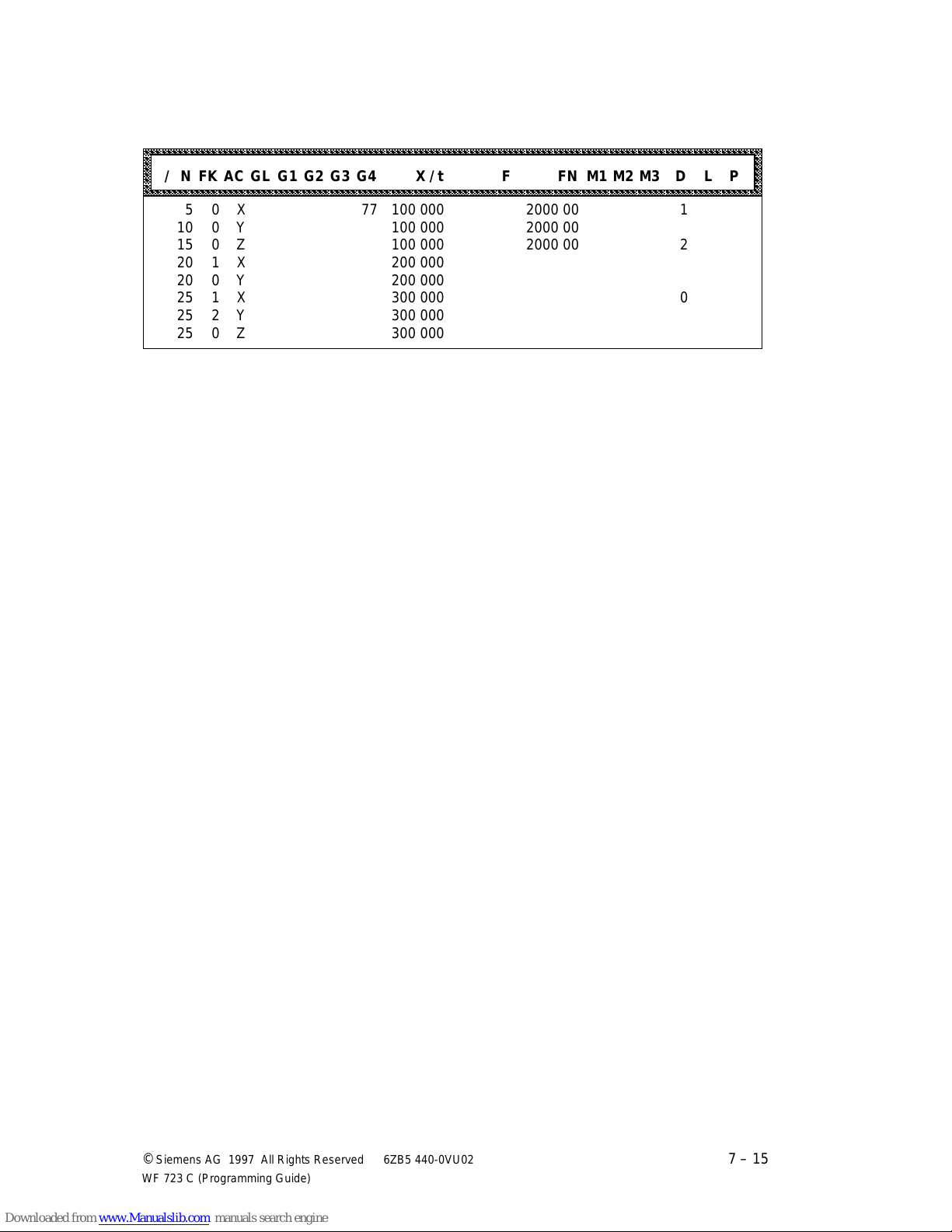
04.97 Programming in S5 Format
aaaaaaaaaaaaaaaaaaaaaaaaaaaaaaaaaaaaaaaaaaaaaaaaaaaaaaaaaaaaaaaaaaaaaaaaaaaaaaaaaaaaaaaaaaaaaaaaaaaaaaaaaaaaaaa
a
a
a
a
a
a
a
a
a
a
a
a
a
a
a
Tool offset memory (chapter 6.2)
aaaaaaaaaaaaaaaaaaaaaaaaaaaaaaaaaaaaaaaaaaaaaaaaaaaaaaaaaaaaaaaaaaaaaaaaaaaaaaaaaaaaaaaaaaaaaaaaaaaaaaaaaaaaa
aaaaaaaaaaaaaaaaaaaaaaaaaaaaaaaaaaaaaaaaaaaaaaaaaaaaaaaaaaaaaaaaaaaaaaaaaaaaaaaaaaaaaaaaaaaaaaaaaaaaaaaaaaaaa
aaaaaaaaaaaaaaaaaaaaaaaaaaaaaaaaaaaaaaaaaaaaaaaaaaaaaaaaaaaaaaaaaaaaaaaaaaaaaaaaaaaaaaaaaaaaaaaaaaaaaaaaaaaaa
aaaaaaaaaaaaaaaaaaaaaaaaaaaaaaaaaaaaaaaaaaaaaaaaaaaaaaaaaaaaaaaaaaaaaaaaaaaaaaaaaaaaaaaaaaaaaaaaaaaaaaaaaaaaa
aaaaaaaaaaaaaaaaaaaaaaaaaaaaaaaaaaaaaaaaaaaaaaaaaaaaaaaaaaaaaaaaaaaaaaaaaaaaaaaaaaaaaaaaaaaaaaaaaaaaaaaaaaaaa
/ N FK AC GL G1 G2 G3 G4 X / t F FN M1 M2 M3 D L P
aaaaaaaaaaaaaaaaaaaaaaaaaaaaaaaaaaaaaaaaaaaaaaaaaaaaaaaaaaaaaaaaaaaaaaaaaaaaaaaaaaaaaaaaaaaaaaaaaaaaaaaaaaaaa
aaaaaaaaaaaaaaaaaaaaaaaaaaaaaaaaaaaaaaaaaaaaaaaaaaaaaaaaaaaaaaaaaaaaaaaaaaaaaaaaaaaaaaaaaaaaaaaaaaaaaaaaaaaaa
5 0 X 77 100 000 2000 00 1
10 0 Y 100 000 2000 00
15 0 Z 100 000 2000 00 2
20 1 X 200 000
20 0 Y 200 000
25 1 X 300 000 0
25 2 Y 300 000
25 0 Z 300 000
a
a
a
a
a
a
a
©
Siemens AG 1997 All Rights Reserved 6ZB5 440-0VU02
WF 723 C (Programming Guide)
7 – 15
Page 91

Programming in S5 Format 04.97
7 – 16 ©
Siemens AG 1997 All Rights Reserved 6ZB5 440-0VU02
WF 723 C (Programming Guide)
Page 92

04.97 Appendix
8 Appendix
8.1 Abbreviations
DIN German Industrial Standard
RAM Random access memory (read-write memory with direct access)
N Block number
G G-function
A, B, C Path information for rotary axes
X, Y, Z Path information for linear axes
I, J, K Interpolation parameters (path information)
S Spindle position/spindle speed
F Feed rate
M M-function
D Tool offset no.
L Subroutine no.
P Number of loops
R R-parameter no.
MD Machine data
I Incremental encoder
SSI Serial encoder
Sp Spindle
SpoW Spindle without encoder
M Machine zero point
R Machine reference point
W Workpiece zero point
WR Workpiece reference point
v Velocity
KA Circle initial point
KE Circle end point
KM Circle centre point
NPV Zero offset
NC Numerical control
RST Reset axis (RESET)
SDZ Spindle speed reached
FK Continue identifier
AC Axis
SA Skip block
WH Stop if
WF Machine tool module
WS Machine tool control
©
Siemens AG 1997 All Rights Reserved 6ZB5 440-0VU02
WF 723 C (Programming Guide)
8 – 1
Page 93

Appendix 04.97
8.2 Index
A
Absolute dimension
for external block change
Absolute dimension, input
Absoute dimension, programming
Acceleration override
Address letter
Assignment of M-functions
Automatic block search
Axis assignment
Axis reset
. . . . . . . . . . . . . . .
. . . . . . . . . . . . . .
. . . . . . . . . . . . . . . . .
. . . .
. . . . . .
. . . . . . . . .
. . . . . .
. . . . . . . .
.
4-34
4-2
6-1
4-39
2-5
2-9
3-5
2-5
4-39
B
Basic definitions
Basic position
Block number
Block search forwards
Block structure
Block transitions
. . . . . . . . . . . . . .
. . . . . . . . . . . . . . .
. . . . . . . . . . . . . . .
. . . . . . . . .
. . . . . . . . . . . . . .
. . . . . . . .
4-19, 4-30
2-1
2-6
2-5
3-5
2-4
C
Call of subroutine . . . . . . . . . . . . 3-3
Chaining . . . . . . 2-1, 4-20, 4-23, 4-26
Chaining with axis velocity . . . . . 4-8
Chaining with rapid traverse . . . . 4-7
Channel structure . . . . . . . . . . . 2-2
Conditions of block search forwards 3-7
Continous loop . . . . . . 2-10, 4-4, 5-1
Coordinate system . . . . . . . . . . . 4-1
Coordination axis . . . . . . . . . . . . 2-3
Coordination of the control signals 2-3
Coupling types . . . . . . . . . . . . . 4-30
D
Dimensions
Direction of processing
Direction of tool offset
Displacements
Dwell time
. . . . . . . . . . . . . . . . .
. . . . . . . .
. . . . . . . . .
. . . . . . . . . . . . . . .
. . . . . . . . . . . . .
2-10, 4-4
4-2
3-1
6-5
2-6
E
Entry point
in subroutine level 1 . . . . . . . . 3-6
in subroutine level 2
in the main program
Exact stop
Execution of subroutine . . . . . . . 3-3
External block change . . . . 2-1, 4-34
. . . . . . . . . . . .
. . . . . . . . .
. . . . . . . . .
4-22-4-24
3-7
3-6
F
Flying actual-value setting
.
2-1, 4-36
G
G-functions
G00
. . . . . . . . . . . . .
G01
. . . . . . . . . . . . .
. . . . . . . . . . . . . . . . . . . . . . .
G04
. . . . . . . . . . . . .
4-10, 4-21, 4-24
4-11, 4-21, 4-24
2-6, 3-4
4-4
G
G30 to G39
. . . . . . . . . . . . . . . . . . . . . .
G43
G44
. . . . . . . . . . . . . . . . . . . . . .
G50
. . . . . . . . . . . . . . . . . . . . . .
. . . . . . . . . . . . . . . . . . . . . .
G51
G53
. . . . . . . . . . . . . . . . . . . . . .
G54
. . . . . . . . . . . . . . . . . . . . . .
G54 to G59
G55
. . . . . . . . . . . . . . . . . . . . . .
G56
. . . . . . . . . . . . . . . . . . . . . .
G57
. . . . . . . . . . . . . . . . . . . . . .
. . . . . . . . . . . . . . . . . . . . . .
G58
G59
. . . . . . . . . . . . . . . . . . . . . .
G63 . . . . . . . . . . . . . . . . . . . . 4-27
. . . . . . . . . . . . . . .
G60
G64
. . . . . . . . . . . . . . .
G66
. . . . . . . . . . . . . . .
. . . . . . . . . . . . . . .
G67
G68
. . . . . . . . . . . . . . . . . . . . . .
G76
. . . . . . . . .
. . . . . . . . .
G77
G87
. . . . . . . . . . . . . . . . . . . . . .
G88
. . . . . . . . . . . . . . . . . . . . . .
G89
. . . . . . . . . . . . . . . . . . . . . .
. . . . . . . . . . . . . . . . . . .
G90
G91
. . . . . . . . . . . . . . . . . . . . . .
G96 . . . . . . . . . . . . . . . . . . . . 4-16
G97 . . . . . . . . . . . . . . . . . . . . 4-16
G99 . . . . . . . . . . . . . . . . . . . . 4-38
. . . . . . . . . . . . . . . .
. . . . . . . . . . . . . . . .
4-22 - 4-24
4-19 - 4-21
4-25 - 4-26
4-25 - 4-26
4-7, 4-20, 4-23, 4-26
4-8, 4-20, 4-23, 4-26
4-2, 6-1
4-39
6-1
6-1
4-34
4-34
4-5
4-5
4-5
4-5
4-5
4-5
4-5
4-5
4-3
4-36
4-36
4-36
4-2
H
Hardware axis
. . . . . . . . . . . . . .
2-5
I
Incremental dimension for external
block change
Incremental dimension input
Interpolation
Interpolation with path velocity
Interpolation with rapid travers
. . . . . . . . . . . . .
. . . . . . . .
2-1, 4-21, 4-24
. . . .
. . .
. . .
4-34
4-2
4-11
4-10
L
Limit switch
Linear
Linear axis
Logic name
Loop-over
Loop-over window
. . . . . . . . . . . . . . . .
. . . . . . . . . . . . . . . . . . . .
. . . . . . . . . . . . . . . . .
. . . . . . . . . . . . . . . .
. . . . . . . . . . . . . . . . . .
. . . . . . . . . . .
4-2
2-6
4-2
2-5
4-26
4-25
M
M00
. . . . . . . . . . . . . . . . . . . . . .
. . . . . . . . . . . . . . . . . . . . . .
M02
M17
. . . . . . . . . . . . . . . . . . . . . .
M18
. . . . . . . . . . . . . . . . . . . . . .
. . . . . . . . . . . . . . . . . . . . . .
M29
5-1
5-2
5-2
5-1
5-2
8 – 2 ©
Siemens AG 1997 All Rights Reserved 6ZB5 440-0VU02
WF 723 C (Programming Guide)
Page 94

04.97 Appendix
M
M30
. . . . . . . . . . . . . . . . . . . . . .
M-functions
Machine data 38
Machine reference point
Machine zero point
Manual block search
Maximum loop-over
Memory capacity
MD 46
MD 47
. . . . . . . . .
. . . . . . . . . . . . .
. . . . . . . .
. . . . . . . . . .
. . . . .
. . . . . . . . . . . . .
. . . . . . . . . . . . . . . . . . .
. . . . . . . . . . . . . . . . . . .
2-9, 4-31, 5-1
. . . . . . .
4-20-4-21
5-2
2-5
4-1
4-1, 4-6
3-6
2-3
4-25
4-25
N
Nesting depth
. . . . . . . . . . .
3-3-3-4
O
Offsets
Output of M-functions after
positioning
Output of M-functions before
positioning
Output of M-functions during
positioning
Overview
. . . . . . . . . . . . . . . . . . . .
. . . . . . . . . . . . . . . .
. . . . . . . . . . . . . . . .
. . . . . . . . . . . . . . . .
4-33
4-32
4-31
. . . . . . . . . . . . . . . . . .
2-6
2-1
P
Path information . . . . . . . . . . . . 2-8
Permanent synchronism . . . . . . . 4-13
Point-to-point positioning . . . . . . 2-1
Position . . . . . . . . . . . . . . . . . . 2-8
Preface . . . . . . . . . . . . . . . . . . . 1-1
Processing step . . . . . . . . . . . . . 2-4
Program end . . . . . . . . . . . . . . . 5-2
Program execution . . . . . . . . . . . 3-1
Program number . . . . . . . . . . . . 2-3
Program start after activation of block
search forwards . . . . . . . . . . . . . 3-8
Program structure . . . . . . . . . . . 2-4
Programming . . . . . . . . . . . . . . . 4-1
Programming guidelines . . . . . . . 3-4
Programming in S5 format . . . . . 7-1
Programming of traversing blocks 4-39
S
SA . . . . . . . . . . . . . . . . . . . . . . 3-2
Selectable synchronism . . . . . . 4-13
Self-holding . . . . . . . . . . . . . . . . 4-2
Skip block . . . . . . . . . . . . . . . . . 3-2
Skippable blocks . . . . . . . . . . . . 3-2
Software limit switch . . . . . . . . . . 4-6
Start signal . . . . . . . . . . . . . . . . 3-1
Stop at block end . . . . . . . . . . . . 5-1
Subroutine call . . . . . . . . . . . . . . 3-3
Subroutine end . . . . . . . . . . . . . 5-2
Subroutine execution . . . . . . . . . 3-3
Subroutine number . . . . . . . . . . . 2-3
Subroutines . . . . . . . . . . . . . 3-1, 3-3
Synchronism . . . . . . . . 2-1, 2-3, 4-13
Synchronism in combination with
interpolation and chaining . . . . . 4-15
T
Tool offset
Tool offset memory
Tool offset number
Tool length offset
Tool length wear
Traversing program
Traversing blocks
Traversing block decoder
. . . . . . . . . . .
. . . . . . . . . .
. . . . . . . . . . .
. . . . . . . . . . . .
. . . . . . . . . . . . .
. . . . . . . . . .
. . . . . . . . . . . .
2-1, 3-4, 6-1
. . . . . .
6-2
2-10
6-3
6-4
2-1
2-4
3-1
V
Variants of tool offset
Velocity
. . . . . . . . . . . . . . . . . . .
. . . . . . . . .
6-3
2-8
W
Workpiece reference point
Workpiece zero point
. . . . .
. . . . . . . . .
4-1
4-1
Z
Zero point offset
. . . . . . .
2-1, 3-4, 4-5
Q
Qualified personnel . . . . . . . . . . 1-2
R
RAM buffering . . . . . . . . . . . . . . 2-1
RAM memory . . . . . . . . . . . . . . 2-1
Range of functions . . . . . . . . . . . 1-1
Read-in enable . . . . . . . . . . . . . 3-1
Reference point - coordinate . . . . 4-2
Reference points . . . . . . . . . . . . 4-1
Reset of axis . . . . . . . . . . . . . . . 4-39
Return . . . . . . . . . . . . . . . 2-10, 5-1
Roll feed . . . . . . . . . . . . . . . . . . 2-1
Roll feed axes . . . . . . . . . . . . . . 2-3
Rotary axis . . . . . . . . . . . . . 2-6, 4-3
©
Siemens AG 1997 All Rights Reserved 6ZB5 440-0VU02
WF 723 C (Programming Guide)
8 – 3
Page 95

Appendix 04.97
8 – 4 ©
Siemens AG 1997 All Rights Reserved 6ZB5 440-0VU02
WF 723 C (Programming Guide)
Page 96

Suggestions
Siemens AG
A&D MC V1
Postfach 3180
D-91050 Erlangen
Fed. Rep.of Germany
From:
Name
Company/Dept.
Address
Telephone /
Suggestions and/or corrections
Corrections
For Publication/Manual:
WF 723 C
Positioning Module
Programming Guide
Order No.: 6ZB5 440-0VU02-0AA3
Edition: April 1997
If you find any printing errors when reading
this publication, please let us know, using
this form. We also welcome any suggestions
to improve the manual.
Page 97

Siemens AG
Bereich Automatisierungs- und Antriebstechnik
Geschäftsgebiet Motion Control Systeme
für Werkzeug- und Produktionsmaschinen
Postfach 3180, D-91050 Erlangen
Federal Republic of Germany
Siemens Aktiengesellschaft
©
Siemens AG 1998
Subject to change without prior notice
Order No. 6ZB5 440-0VU02-0AA3
Printed in the Federal Republic of Germany
232/892115 PG 04980.1
 Loading...