

Siemens WAC 11 Installation Instructions Manual
s
WAC 11
WLC 11 UK
20 800 056.0-010
Installation Instructions
Fig. 1
T
R
Q
Q
W
E
1. Product description
The WAC 11 is used to verify audio alarms. It is fitted with a
speaker and microphone. The audio signal is connected directly
to the central control unit via an audio module (e.g. WMA 11) or
via a WAC 12, which acts as a master.
W
2. Supply package
The WAC 11 UK package contains the following
- One WAC 11
- One WLC 11 UK language kit complete with:
- Installation instructions.
3. Mounting instructions
The WAC 11 is designed for mounting in dry indoor rooms.
To ensure good acoustics, note the following points.
- Mount 2 to 2.5 m above floor level.
- Maintain adequate distance from noise sources (ven ti la tion
openings, fans etc.).
- Direct towards the centre of the space to be monitored.
- Do not mount on vibrating surfaces.
- The maximum length of the audio connection between the
WAC 11 and central control unit is 200 m.
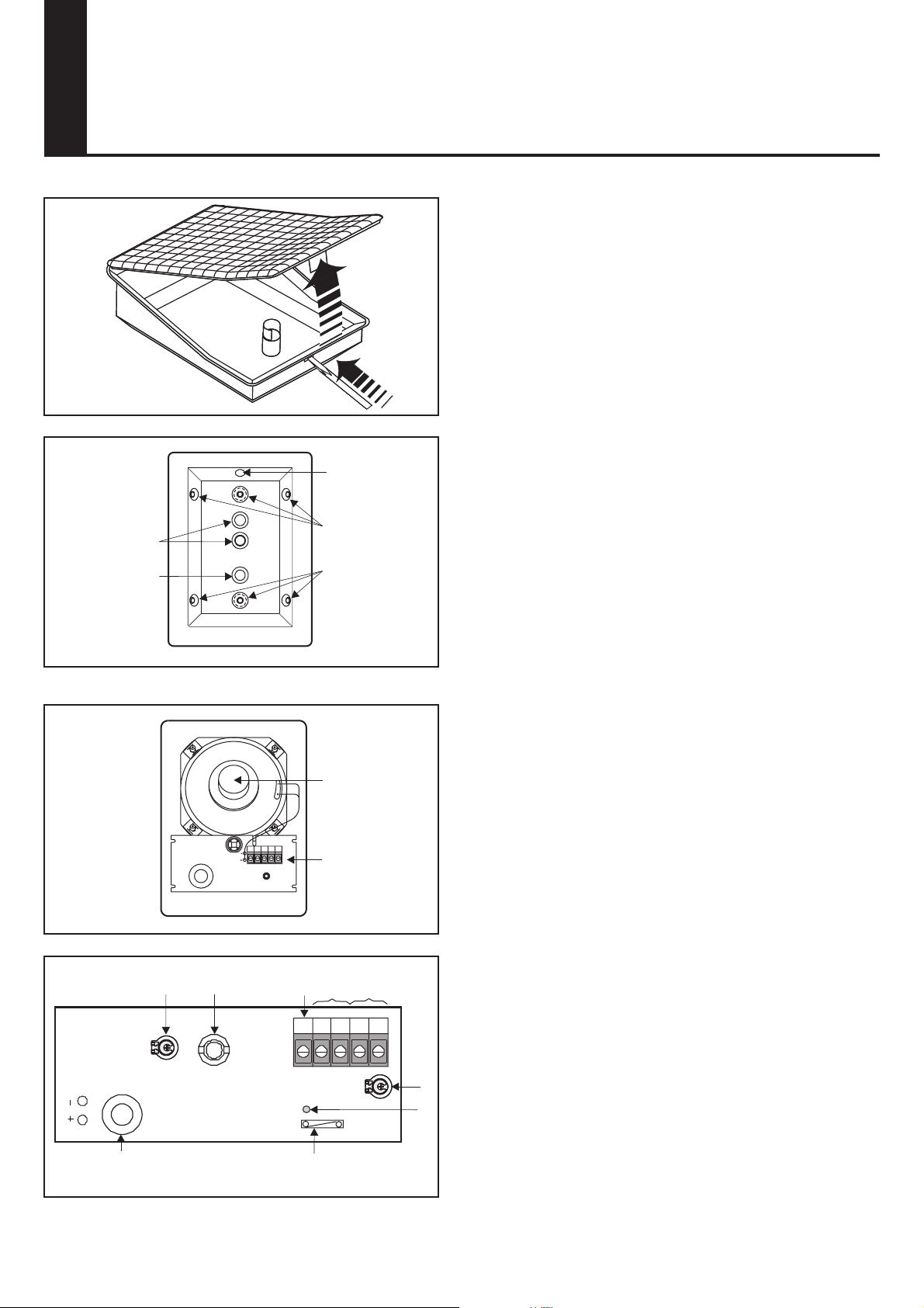
3.1 Opening the housing (Fig.1)
1 - Using screwdriver Q, press locking tab to release.
2 - Lift off cover W.
Fig. 2a
8AA9978 - D0 -05/10/2003 - UK -
Fig. 2b
T
Y
3.2 Product overview (Fig. 2)
- Knockouts Q, T for cable inlet.
- Knockouts W, E for attachment of housing.
- Knockout R for disconnection monitor screw.
Y
NC
T
-A
+A
T
- Speaker Y.
- WMC 11 circuit board U.
U
3.3 WMC 11 circuit board (Fig. 3)
- Audio connection O.
- Tamper output I
- Free terminal U
- LED W, flashes to outside during monitoring (microphone
active).
- Switch E for "microphone active" LED.
- Tamper switch Y.
- Microphone R.
- Potentiometer Q for speaker volume.
- Potentiometer T for microphone sensitivity.
NC
U
DS1
O
I
+A
T
-A
T
Q
W
Fig. 3
R
E
3.4 Mounting (Fig. 4)
- The housing can be mounted flat or at 45o.
- Always use two attaching points which are one above the
other, including for corner mounting.
4. Wiring
Fig. 4
AE-
AE+
T-
WAC 12 WAC/WAS 11
NC
T+
Fig. 5a
A+
A-
e.g. WMA 11 WAC 11
Fig. 5b
AE+
AE-
TTA-A+
A+
A-
A-
WAS 11
A+
TTA-A+
A-
Audio to
other
WAS 11
A+
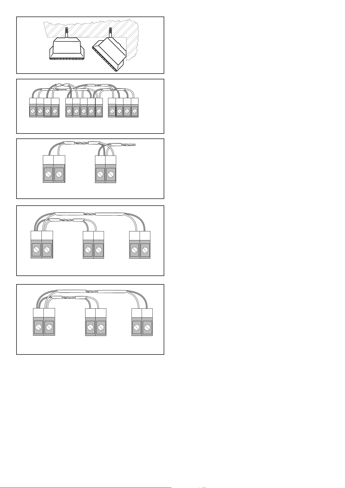
4.1 Audio (Fig. 5)
To avoid side-tone, a twisted core pair at least 0.6 mm in dia. must
be used. The audio connection to the central control unit must
not be more than 200 m long. The audio output depends on the
cable length and core cross-section. The audio output (A- and
A+) of the WAC 11 is connected to the audio input (AE- and AE+)
of the WAC 12, which acts as a master (Fig. 5a).
Alternatively, the audio output (A- and A+) of the WAC 11 can be
directly connected to the audio input (A- and A+) of the central
control unit (e.g. WMA 11) (Fig. 5b). Where several WAC 11 are
used, all WAC 11 must be connected directly to the WAC 12 (Fig. 5c) or
to the central control unit (Fig. 5d) to obtain optimum performance.
4.2 Tamper (Fig. 5a)
The tamper outputs (T,T) of the WAC 11 and WAS 11 are connected
in series to the tamper inputs (T- and T+) of the WAC 12.
5. Start-up
5.1 Microphone sensitivity
The sensitivity of the microphone must be matched to the room
and ambient noises (potentiometer T, Fig. 3).
Where sensitivity is reduced, the reception of quiet signals
naturally reduces. The following ranges are normally obtained.
- Approx. 3.5 m with potentiometer on min.
- Approx. 6.5 m with potentiometer on mid position.
- Approx. 8.5 m with potentiometer on max.
5.2 Speaker
Set the required volume using potentiometer (Q, Fig. 3).
WAC 12
WAC 11 WAC 11
Fig. 5c
A+
A-
WMA 11 WAC 11 WAC 11
A-
A+
Fig. 5d
A-
A+
5.3 "Microphone active"LED
- Switch (E, Fig. 3) open: LED active.
- Switch (E, Fig. 3) closed: LED inactive.
6. Close housing
1 - Engage cover at the top in the openings in the base of the
housing.
2 - Close the cover by pushing downwards until the locking
tab engages.
7. Technical data
Supply Through audio
Power consumption, quiescent state 0 mA
Power consumption, "challenge" state 7 mA
Operating temperature -10°C to +55°C
Housing material ABS
Dimension in mm H 145 x B 105 x T 70
Safety class IP 30
Weight 230g
The right to make technical changes to the described equipment without prior notice is
reserved.
 Loading...