

Page 1

VideoRec
RA
Service Instructions
RA53-050.061.01.03.02 English
Replaces: RA53-050.061.01.02.02 08.95
Proprietary data, co mpany confidential. All rights reserved.
Confié á titre de secret d’ entreprise. Tous droits resérv és.
Confiado como secreto industrial. Nos reservamos todos los derechos.
Copyright (C) Siemens AG 1994
Page 2

Revisions
Chapter Page Rev.
all all 01
all all 02
all all 03
Siemens AG TDRA 1 RA53-050.061.01 VideoRec
Medizinische Technik Rev. 03 08.95
Page 3

Table of Contents 0-1
Page
1 General Remarks 1-1
General Remarks/Function Information 1-1
Required Aids/ Tools 1-2
2 Description of Assemblies 2-1
S-VHS Video Recorder (Sony) 2-1
SSI 22 VCR Interface 2-2
VSC 36 SHC Video Scan Converter, 50 or 60 Hz 2-3
Cabling Schematic 2-5
3 Troubleshooting 3-1
4 Repair 4-1
Replacing the Sony Video Recorder 4-1
Replacing the SSI22 VCR Inter face 4-2
Replacing the Video Scan Converter 4-4
5 Adjustment 5-1
General Remarks 5-1
Adjusting the Amplitude Parameters for
VCR Record Mode 5-2
Illustration of the Principle Used for Record Mode 5-2
With HICOR: Adjusting the Amplitudes and Size/Position Parameters for
VCR Playback (Upscan, H Norm). 5-4
With Multistar T.O.P: Adjusting the Amplitudes and Size/Position
Parameters for VCR Playback (Upscan, H Norm). 5-6
With Polytron / Digicor: Adjusting the Amplitudes and Size / Position
Parameters for VCR Playback (Upscan, H Norm). 5-8
Adjusting the Cosine Enhancer 5-10
6 Changes Versus the Previous Edition 6-1
Siemens AG TD RA 3 RA53-050.061.01 VideoRec
Medizinische Technik Rev. 03 08.95
Page 4

0-2 Table of Contents
Page
Siemens AG TD RA 3 RA53-050.061.01 VideoRec
Medizinische Technik Rev. 03 08.95
Page 5

General Remarks 1-1
General Remarks 1
General Remarks/Function Information
● The VideoRec is composed of:
S-VHS Recorder (SVO-9500MD(P) with built-in par allel interface.
Scan Converter VSC 36 SHC 50/60.
SSi22 VCR interface with cable set.
● With the VideoRec, N or H video signals can be recorded on N-SVHS video
recorders (Sony).
● With H video signals, a downscan selection t akes place automatically in the VSC 36
SHC scan converter.
● Playback takes place via the upscan of the VSC 36 SHC on the H control room
monitor or on the control room and examinat ion room monitors.
● The control of automatic exposure (ci ne/DCM fluoro can be jumpered) takes place
over the SSI22 VCR interface of the X-ra y system(M96, M96C, system distributor)
● The SSI22 VCR interface is powered over the X-r ay system with 24V.
● Automatic monitor switch-over by t he interface, and there is also an automat ic
switch-over to VCR playback in th e interface when there is playback of the S-VHS
recorder. If radiation is triggered, the monitors are swi tched over to the X-ray system
as a default setting.
● NOTE: If cine is selected while the VCR i s in the playback mode, the video recorder
is switched immediately to record ! This means that any scene being played back will
be written over!
● Warning signal generator (in the SSI22 VCR interface),
- when the tape reaches the end
- when there is no video cassette inser ted
- when the VCR power is switched off
- when the VCR is operated manually durin g cine, a warning signal is soun ded.
● Warning output over X4, Pin 6:
- can be switched on/off using a jumper, see paragraph entitled, Recording .
- at the end of the tape
- if no video cassette is in serted
- if the VCR power is switched off
- if the interface po wer is switched off
- if a manual control is made at t he VCR during automatic recording.
● The power line voltage for the VideoRec i s 230V; except for 60 Hz the video recorder
must be connected to 120V.
● For spare parts, see the Video Components Spare Parts List, RA53-050.081.01...
● Note: when setting up the video reco rder, make sure there is good air circul ation
around it. The minimum space between the VCR and the sides of built-in consoles or
other components must be at least 3 cm.
If two video recorders are conf igured in a biplane system, to permit goo d heat
dissipation, under no circumsta nces may they be closer than 3 cm to each other, i .e.,
they may not be placed next to each other in th e optinally available control console.
However it is possible to place one on t op of the other.
Pay attention to good air circul ation.
Siemens AG TD RA 3 RA53-050.061.01 VideoRec
Medizinische Technik Rev. 03 08.95
Page 6

1-2 General Remarks
Required Aids/Tools
● Standard service tool kit, as def ined in ARTD, Part 3
● Memory oscilloscope, as defined in ARTD, Part 3
● Mavo monitor, as defined in ARTD, Part 3
Part No. 97 02 432 Y0526
● Digital voltmeter, as defined in ARTD, Part 3
● TV Dynamics Test
● BNC connector, Part No. 30 06 590
BNC
NEG
BNC
POS
BNC
NEG
Siemens AG TD RA 3 RA53-050.061.01 VideoRec
Medizinische Technik Rev. 03 08.95
Page 7
Description of Assemblies 2-1
Description of Assemblies 2
S-VHS Video Recorder (Sony)
● Recording of N video signals on S-VHS tape s.
● Playback of N-recorded S-VHS tapes.
● Can be remotely controlled over a bui lt-in 34-pin interface.
IMPORTANT: Only the S-VHR recorder (Sony) s hipped with VideoRec has this
interface!
● The 60Hz model can be operated only at 120V!
Video input
from SSI / XX3
~ AC IN
Video output
to SSI / XX4
34-Pin i nterface
REMOTE
75 Ohm terminal resistor *
Power connector socket
* Note: The terminal resistor for the loop-through output must be set to ON.
Siemens AG TD RA 3 RA53-050.061.01 VideoRec
Medizinische Technik Rev. 03 08.95
Page 8
2-2 Description of Assemblies
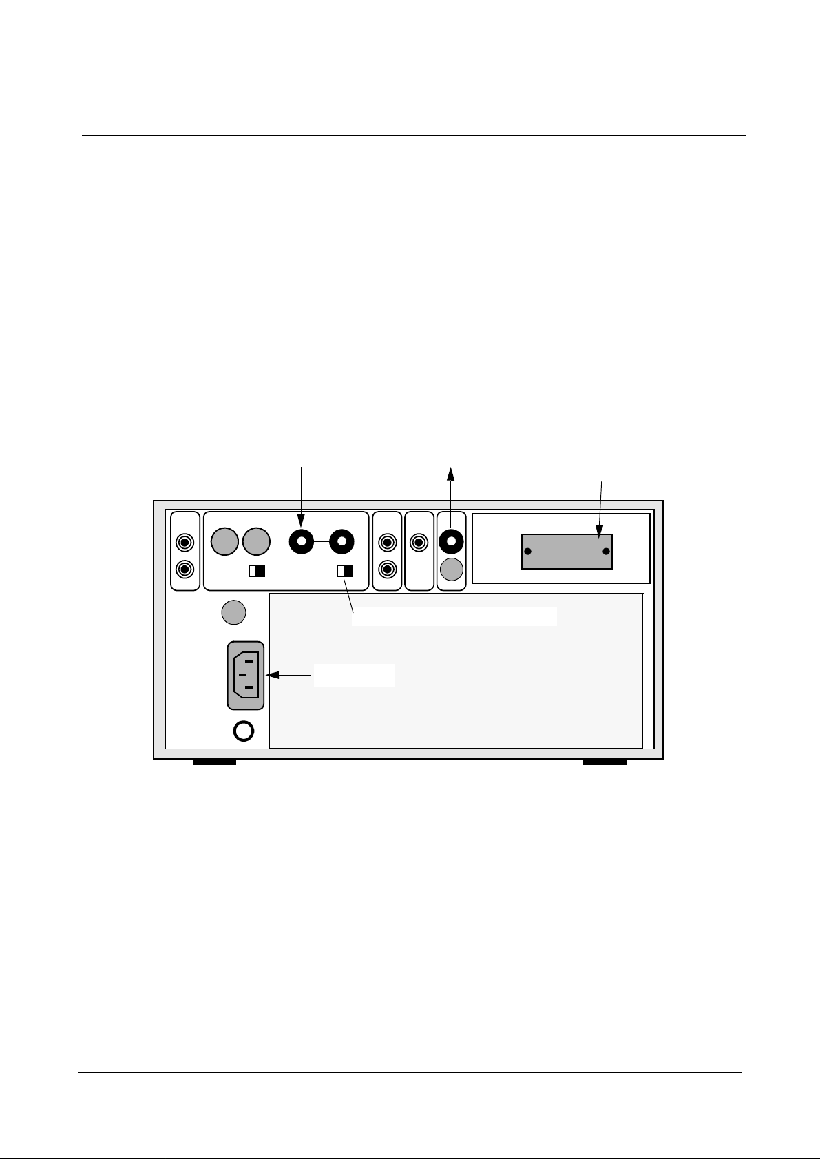
SSI 22 VCR Interface
● LED display of power On.
● 2x optical video separation (re quired, because the video recorder may be operat ed
with a ground wire and ground loops mu st be avoided), for input and output of the
video recorder.
● Automatic control of record f unction of the video recorder, dependi ng on the X-ray
system.
● Control of monitor switch- over and of upscan function in the VSC 36 SHC with vi deo
recorder playback.
● Starting with Serial No. 95391, a Cosi nus Enhancer (edge enhancement) for VCR
recording is int egrated.
● Warning signal output to X4 Pin 6. Output “only“ with selection of record!
Monitored functions:
When no cassette is inserted.
When the tape is at the end.
When there is no power to the inte rface.
If the recorder is manually operated during an automatic recordi ng.
Up to Serial No. 95334 the transis tor switches to ground!
Starting with Serial No. 95334 or when us ing the repair/replacement proc edure,
when there is a warning ground is sent out (via transistor) with OK + 24V over
2.7kOhm .
● For jumpering of the different f unctions, see the section on Repair .
XX1
Video input
from VSC 36 SHC
X7
XX2
XX3
XX4
Video output
to video recorder
BAS IN
Video output
to VSC 36 SHC
X3
X1
Video recorder
34-pin interface
Video input
from video recorder
BAS OUT
X2
X3
VSC36 SHC
X2
X4
KVTR connector
(M96 or M96C)
Power switch
Power line connector
Note: The spade connectors on the quick connectors above coax sockets XX1 and XX2 are used to connect the external
shielding of the triax cable. Connector X2 is not used.
Siemens AG TD RA 3 RA53-050.061.01 VideoRec
Medizinische Technik Rev. 03 08.95
Page 9

Description of Assemblies 2-3
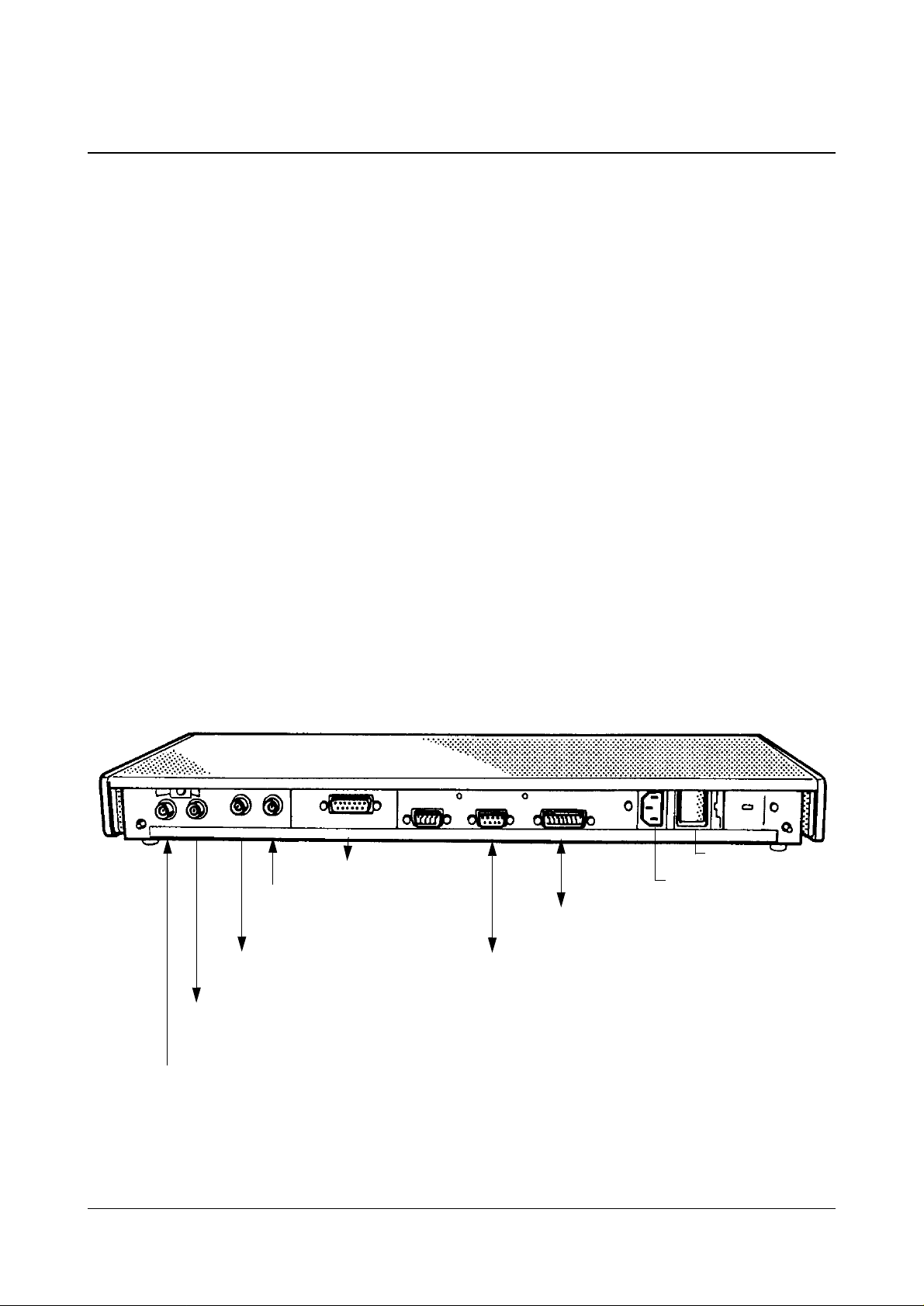
VSC 36 SHC Video Scan Converter, 50 or 60 Hz
● LED display of power ON.
● NOTE: two different scanners are needed for 50 and 60 Hz video scan rates.
● Automatic recognition of H-line video i nput signals and switch-over to downs can or
bypass with N video signals.
● Adaptation of the different i nput signals to a 1V standard signal for t he video
recorder in the downscan mode.
● Depending on the control by the video recor der or X-ray system
(via the SSI22 VCR interface):
Upscan mode for VCR playback.
Monitor switch-over to X-ray syst em or VCR playback.
Adaptation of the 1V
1.4V
for upscan.
pp
video signals from the video recorder to HICOR monitors to
pp
X1
X2
X3
SSI 22
XX2
SSI 22
X3
Note: The spade connectors on the quick connectors above coax sockets XX1 and XX2 are used to connect the external
shielding of the triax cable. Connectors X1 and X10 are not used.
X4 X5
HICOR output “VCR“ or from
Examination room Live monitor in DIGICOR systems
X6
X7
SSI 22 XX1
Control room monitor
HICOR output “Mon. 2“
X9
X8
HICOR output “Mon. 1“
X10
Power switch
Power line connector
Examination room monitor
Siemens AG TD RA 3 RA53-050.061.01 VideoRec
Medizinische Technik Rev. 03 08.95
Page 10

2-4 Description of Assemblies
Siemens AG TD RA 3 RA53-050.061.01 VideoRec
Medizinische Technik Rev. 03 08.95
Page 11

Description of Assemblies 2-5
r
Cabling Schematic
Digital System / TV
N or H, 50 or 60HzExamination room Control room
X9
X8
VSC 36SHC
Jumper
X6
X5
X4
X2
X3
XX2
X7
XX1
VCR Interface SSI22
opt. video separation
opt. video separation
fac. settings
fac. settings
X3
7/8 = +24V
2 = Stand By
3 = Record
6 = Warning *1
1/9/10/11/12/13/
14/15 = Ground
M96 /M96C
X4
System distributo
7/8
Ex. room
Con. room
XX4
OUT
Sony
SVO9500MD(P)
XX3
IN
34-pin connector
X1
*1 Warning signal output, see paragraph
“Description of Assemblies“, SSI 22 VCR Interface .
ggg
Siemens AG TD RA 3 RA53-050.061.01 VideoRec
Medizinische Technik Rev. 03 08.95
Page 12

2-6 Description of Assemblies
Siemens AG TD RA 3 RA53-050.061.01 VideoRec
Medizinische Technik Rev. 03 08.95
Page 13

Troubleshooting 3-1
Troubleshooting 3
S-VHS Recorder, Sony SVO 9500 MD(P)
The recorder is thought of as a black box and must be replaced completely.
IMPORTANT: Every returned re corde r must be acco mpnaied by a detail ed descr ip tion
of the malfunction!
SSI22 VCR Interface
No function or only partial function - chec k the power fuses on the rear of the unit (at
the power input) and check the internal fuses .
IMPORTANT: Every returned inter face must be ac companied by a det ailed descr iption
of the malfunction!
MainFuse
F301
F302
Rückseite / rear side
F 2
F 1
F101
F151
F251
F201
VSC 36 SHC Scan Converter
No function or only partial function - chec k the power fuses on the rear of the unit (at
the power input) and check the internal fuses .
IMPORTANT: Every returned scanner must be accompanied by a detailed description
of the malfunction!
MainFuse
Rückseite / rear side
F 1 F 2
Siemens AG TD RA 3 RA53-050.061.01 VideoRec
Medizinische Technik Rev. 03 08.95
Page 14

3-2 Troubleshooting
Siemens AG TD RA 3 RA53-050.061.01 VideoRec
Medizinische Technik Rev. 03 08.95
Page 15

Repair 4-1
Repair 4
Replacing the Sony Video Recorder
●
NOTE: Only the model l isted in the Spare Parts List
(RA53-050.081.01...) (additiona l interface) may be used.
Only an SVO 9500 MDP (Pal, 230 V) may be used with 50 Hz power
line systems.
Only an SVO 9500 MD (NTSC, 120 V) may be used with 60 Hz
power line systems.
● Connect the video input / output an d interface cables “as before”.
● Set the 75 Ohm termination switch to ON (no loop-through mode), with connection of
a video printer to OFF (termina tion is in printer).
● Y-Enhancer:
The video recorder is equip ped with a switchable Y-Enhancer (edge enhancement
with playback). This enhancer i s set to ON when shipped from the factory and must
be switched off as follows:
CTL / MENU - set switch in the “MENU” position .
ITEM - continue to press key until “4 EN-.... ” appears in the display.
DATA - press key until “4 EN--OF” is set.
CTL / MENU - set switch back to the “CTR” position.
Siemens AG TD RA 3 RA53-050.061.01 VideoRec
Medizinische Technik Rev. 03 08.95
Page 16

4-2 Repair
Replacing the SSI22 VCR Interface
Jumper Positions
*1
*2
Jumper
X5
X6
X7
X8
X9
Starting with Serial No. 95 334 a warning signal is output over socket X4, Pin 6
(used with MULTISTAR T.O.P configured with the cine option).
Spare parts have been upgraded.
When used with the Multistar T.O.P. or CARD III, it is always set to “ON“. Setting for
“only“ record or for fluoro and record see the Configuration Guide for
Multistar T.O.P. or the POLYDOROS IS Service Instruction for CARD III.
Norm
OFF
OFF
ON
OFF
ON
Function
OFF-Warning signal output when there is a recording error.
*1
ON - No warning signal output with recording error.
ON-Playback on control rooml/examination room monitor.
OFF-Playback on control room monitor
ON- Cine/DCM/Acquisition recording only.
*2
OFF- Fluoro and Cine/DCM/Acquisition recording.
Always set to OFF
On - Warning signal when there is a recording err or.
OFF - No warning signal with recording error
Cosine Enhancer:
Up to Serial No. 95 391 “several“ enhancers were built in ; with these enhancers the
switch must be set to the “0 - position“ (off).
Starting with Serial No. 95 391, the Cosine Enhancer is fully functional; for adjustment,see the chapter “Adjustment“.
No further adjustments are necessary.
Siemens AG TD RA 3 RA53-050.061.01 VideoRec
Medizinische Technik Rev. 03 08.95
Page 17

Repair 4-3
VCR - Interface SSI 22
.
Switch
X 5/6/7/8/9
1
3
2
1-2 OFF
FINE - 0 - COARSE
COSINE ENHANCER
2-3 ON
Main fuse
Power Supply
Rückseite / rear side
FINE - 0 - COARSE
COSINE ENHANCER
X7
X8
X9
XXX
Interface
Cosine Enhancer
X6
Je nach Seriennummer
depending on Serial No.
X5
OTV
FINE - 0 - COARSE
COSINE ENHANCER
OTV
Siemens AG TD RA 3 RA53-050.061.01 VideoRec
Medizinische Technik Rev. 03 08.95
Page 18

4-4 Repair
Replacing the Video Scan Converter
Connect all inputs/outputs as they were previously connected.
Switch Positions
DIGICOR
with
control
room
monitor
S2 OFF ON OFF ON Switchable terminal r esist or for X4 in put
S4/5 ON OFF ON OFF Loop-through of X4 input to X6 output
S6 OFF OFF OFF ON ON = Bypass Scanner with Power Off.
S7 OFF OFF OFF ON Terminal resistor for X5 input with
Remove Remove Remove Leave Change of the pot entiometer adjust-
*
DIGICOR
without
control
room
monitor
Polytron
Hicor/
Multistar
T.O.P.
Function
OFF =No Bypass with Power Off.
UP scan.
ment range for DOWN Scan
* Remove the parallel resistor to R17, see illustration.
J1 to J30 factory settings - specifications for conversion / size / position.
MainFuse
Rückseite / rear side
S2
S6
S7
S4
S5 unter / below S4
if no S5, then
S4 = S4/S5
P1
F 1 F 2
P3
P5
Scan Converter VSC 36
ON - OFF
P1
Parallel resi s to r
(820 Ohm)
Siemens AG TD RA 3 RA53-050.061.01 VideoRec
Medizinische Technik Rev. 03 08.95
R17
S2/4/5/6/7
Page 19

Adjustment 5-1
Adjustment 5
General Remarks
Adjustment is divided into three secti ons:
VCR record mode
VCR playback mode
Cosine enhancer adjustment.
For adjustment, see below.
Note:
The Simomed H monitor has its own set of adjustment parameters for each norm.
This means that if necessar y, every norm which i s being used must be adjusted (i mage
alignment and contrast)!
e.g. HICOR:
With the HICOR, the 1249 lines /100 Hz (1023 lines/120 Hz) norm is used
for the monitor.
With the VideoRec, the 1249 lines /50 Hz (1023 lines/60 Hz) norm is used
for the monitor.
With bypass, the 1249 lines/50 Hz (1023 line/60 Hz) norm is used for the
monitor.
e.g. MULTISTAR T.O.P:
With a digital system, 2249 lines/60 Hz are used for the monit or,
With bypass, 1125 lines/60 Hz are used for the monitor (the same norm
for the monitor as with 2249 lines/60 Hz !!),
With the VideoRec, 1249 lines/50 Hz (1023 lines/60 Hz) are used for the
monitor.
Siemens AG TD RA 3 RA53-050.061.01 VideoRec
Medizinische Technik Rev. 03 10.95
Page 20

5-2 Adjustment
Adjusting the Amplitude Parameters for
VCR Record Mode
Illustration of the Principle Used for Record Mode
N and / or H Norm
Digital System
● If a cosine enhancer is configured ( see the Chapter on Replacement), it must be
H Norm
N Norm
Scan Converter
XX1
N Norm
X7
VCR
Interface
OTV
switched off during the adjus tment (in the 0 position).
● Feed in the SMPTE test pattern for the digi tal system.
If a digital system is not conf igured, a recording of the TV dynamic test (rec ord mode)
can also be used (field 2L must have the max. amplitude).
● Adjusting the output amplitudes :
Connect the oscilloscope Channel 1 to ou tput X7 using BNC connectors
(scan converter), set 200 mV, 5 ms, Trigger int. Channel 1
- If there is “only“ an N input, there is no adjustment.
- With an N input and in the H backup mode (e.g. HICOR) etc. :
Measure the BA amplitude with the N Norm and with the H Norm
Use P2 to adjust the S portion to 0.3V, +/-30mV.
Use P4 to adjust the BA portion to the same value as for the
N Norm, but max. 0.7V, +/- 30mV.
- With “only“ the H Norm:
Use P2 to adjust the S portion to 0.3V, +/-30mV.
Use P4 to adjust the BA portion to 0.7V, +/ -30mV.
Connect the oscilloscope Channel 1 to ou tput XX3 (VCR Interface) using
BNC connectors, set 200 mV, 5 ms, Trigger int. Channel 1
- Use potentiometer R151 for VCR IN (VCR Interface) to adjust to
1V, +/-30mV BAS.
● Adjustment of the downscan size / positi on parameters (horizontal only):
If there is “only“ the N input, th ere is no adjustment.
With a H input, carry out the adjustment as follows if needed.
Correct adjustment of the upscan si ze/position parameters is prerequ isite, see
paragraph “Use....... ...... : to adjust the amplit ude and size/position parameters“ !!
The setting can only be changed prior to VCR rec ord and can only be evaluated with
VCR playback; change the potentiome ter setting only slightly !!
Use P6 to adjust the horizontal pos ition, centered on the monitor.
Use P8 to adjust the horizontal size ( with a circle, it must be round) .
XX3
VCR
● If a cosine enhancer is configured, it must be switched back on.
Siemens AG TD RA 3 RA53-050.061.01 VideoRec
Medizinische Technik Rev. 03 10.95
Page 21

Adjustment 5-3
VSC 36 Scan Converter
Main fuse
Rückseite / rear side
F 1
F 2
X10
X9
P2
P6
Rückseite / rear side
X8
P8
X7
XX4
X6
X5
P4
X4
X3
SSI22 VCR Interface
XX3
XX2
XX1
X2
X1
Power Supply
X7
X8
X9
XXX
Interface
Cosine enhancer
X6
X5
OTV
fom VCR Output
FINE - 0 - COARSE
COSINE ENHANCER
OTV
to VCR Input
OTV
Amplification
for XX3
output
(VCR IN)
Siemens AG TD RA 3 RA53-050.061.01 VideoRec
Medizinische Technik Rev. 03 10.95
Page 22

5-4 Adjustment
With HICOR: Adjusting the Amplitudes and Size/Position
Parameters for VCR Playback (Upscan, H Norm).
● If a cosine enhancer is configured ( see Chapter Replacement), it must be switched
off during the adjustment (i n the 0 position).
● Make a dynamics tes t recording with the HICOR.
- Use the Mavo monitor to measure the brightness in Fields 2L and 5R (monitor)
and make a note of the results.
● Switch off the HICOR (backup mode) use the Ser vice PC to adjust the ssame
brightness on the monitor as wit h the HICOR (foreground - 2L field/backgrou nd - 5R
field, see Simomed H Adjustment Instruc tions).
● With the HICOR switched on, make a VCR recording.
● Play back the recording (Pause - Freeze) .
- Adjusting the OTV amplification (VCR output):
Connect the oscilloscope Channel 1 to output XX2 (VCR Interface, from VCR
output), set 200 mV, 5 ms, Trigger int. Channel 1
Use potentiometer R251 in the OTV (for XX2 output, see illus tration) to adjust th e
BAS amplitudes to 1V BAS, +/-30 mV.
- Adjusting the upscan amplitudes:
Connect the oscilloscope Channel 1 to outpu t X6 (output to cont rol room monitor )
of the VSC 36 SHC (parallel to the monitor), set 200 mV, 5 ms, Trigger int.
Channel 1. Use P1to adjust the S portion to 0.3 V, +/-30 mV.
Mavo monitor:
Use P3 in field 5R and use P5 in field 2L to adjust the same brightness as was
measured with the dynamics test recording. Alternately repeat the adjustment.
● Adjust the upscan size/position p arameters:
IMPORTANT: This adjustment requires that the monit or be correctly adjusted
(each Norm must be adjusted separately !). If necessary, monitor adjustment ca n
be carried out as follows:
With the Videomed S, select the grid (see Videomed S Ser vice Instructions) set
the HICOR to bypass mode, (i.e., 50 or 60Hz Norm is set), carry out a size/
position adjustment for the monit or.
With the Videomed C, feed in the grid pattern gen erator; use the same procedure.
Or if using the Monitor Multinorm Testb ox, select the grid and Videomed S (50 Hz/
1249 lines or 60Hz/1023 lines).
- Make a VCR recording using a somewhat smaller collimation (for H and V determination).
- Playback image must be horizontally centered on the monitor and H:V must be
correct (with the circle - round, with the collimator - square).
If vertical size / position are not adjustable (monitor adjustment may be required).
Use P7 to adjust the horizontal position, centered to the monitor.
Use P9 to adjust the horizontal size (with the circle, must be round).
Alternately readjust the position / size.
IMPORTANT: no synchronization problems may occur, e.g. position/size disturbing the synchronization range! If this is the case, use P10 for size and P12 for
position and adjust the input parameters (memory) (P7 / 9 = used to adjust the
memory output parameters).
Siemens AG TD RA 3 RA53-050.061.01 VideoRec
Medizinische Technik Rev. 03 10.95
Page 23

Adjustment 5-5
● If a cosine enhancer is configured, it must be switched back on.
VSC 36 Scan Converter
Main Fuse
Rückseite / rear side
F 1 F 2
X10
P1
X9
Rückseite / rear side
P7
X8
P9
X7
XX4
X6
P10
X5
P3
P12
X4
P5
X3
SSI22 VCR Interface
XX3
XX2
XX1
X2
X1
FINE - 0 - COARSE
COSINE ENHANCER
X8
X9
XXX
Interface
X7
X6
X5
OTV
Amplification
for XX2
output
(VCR OUT)
Power Supply
Siemens AG TD RA 3 RA53-050.061.01 VideoRec
Medizinische Technik Rev. 03 10.95
Cosine enhancer
OTV
fom VCR Output
OTV
to VCR Input
Page 24

5-6 Adjustment
With Multistar T.O.P: Adjusting the Amplitudes and Size/
Position Parameters for VCR Playback (Upscan, H Norm).
● If a cosine enhancer is configured ( see Chapter Replacement), it must be switched
off during the adjustment (i n the 0 position).
● Make a dynamics test recording with the Polytron T.O.P.
- Use the Mavo monitor to measure the brightness on the monitor in fields 2L and
5R and make a note of the results.
- Make a VCR recording using the dynamics test.
● Play back the recording (Pause - Freeze) .
- Connect the oscilloscope Channel 1 to output XX2 (VCR I nterf ace, f rom VCR out put); set 200 mV, 5 ms, Trigger int. Channel 1.
- Adjusting the OTV amplification (VCR output):
Use the potentiomerter in the OTV (for XX2 output, see illustration) to adjust the
BAS amplitudes to 1V BAS, +/-30 mV.
- Adjusting the upscan amplitudes:
Connect oscilloscope Channel 1 to output X6 (outp ut to the contro l room monitor)
of the VSC 36 SHC (parallel to monitor); set 200 mV, 5 ms, Trigger int. Channel 1
Use P1 to adjust the S portion to 0.3 V, +/-30 mV.
Use P3 to adjust the A portion of the int. DA
converter to 0V , +5 mV .
Use P5 to adjust theBA portion to 0.7V, +/-30 mV.
int. A signal
0V level
- Adjusting monitor contrast using the VCR:
Using the Service PC, set the same brightness on the monitor (foreground - 2L
field /background - 5R field, see Simomed H Adjustment Instructions) as was
measured for the dynamics test recording. Alternately repeat the adjustment.
● Adjusting the upscan size / positi on paramerters:
IMPORTANT: This adjustment requires that the monit or be correctly adjusted
(each Norm must be adjusted separately!) . If needed, the monitor adjustment can
be carried out as follows:
If using the Monitor Multinorm Testbox, select grid and Videomed S (50 Hz/
1249 lines or 60Hz/1023 lines).
- Make a VCR recording using a somewhat closed collimator (for H and V determination).
- Playback must be horizontally centered on the monitor and H:V must be correct
(with the circle - round, with the collimator, square).
If vertical size / position are not adjustable (monitor adjustment may be required).
Use P7 to adjust the horizontal position, centered to the monitor.
Use P9 to adjust the horizontal size (with circle, it must be round).
Alternately repeat the adjustment of position / size.
IMPORTANT: No synchronization problems may occur, e.g. posit ion / size disturbing the synchronization r ange! If this is t he case, use P10 for si ze and P12 for position to adjust the input parameters (memory) (P7 / 9 = adjustment of the output
parameters of the memory).
● If a cosine enhancer is configured, it must be switched back on.
Siemens AG TD RA 3 RA53-050.061.01 VideoRec
Medizinische Technik Rev. 03 10.95
Page 25

Adjustment 5-7
VSC 36 Scan Converter
Main Fuse
Rückseite / rear side
F 1
F 2
X10
P1
X9
Rückseite / rear side
P7
X8
P9
X7
XX4
X6
P10
X5
P3
P12
X4
P5
X3
SSI22 VCR Interface
XX3
XX2
XX1
X2
X1
Power Supply
X7
X8
X9
XXX
Interface
Cosine enhancer
X6
X5
OTV
fom VCR Output
FINE - 0 - COARSE
COSINE ENHANCER
OTV
to VCR Input
OTV
Amplification
for XX2
output
(VCR OUT)
Siemens AG TD RA 3 RA53-050.061.01 VideoRec
Medizinische Technik Rev. 03 10.95
Page 26

5-8 Adjustment
With Polytron / Digicor: Adjusting the Amplitudes and Size /
Position Parameters for VCR Playback (Upscan, H Norm).
● If a cosine enhancer is configured ( see Chapter Replacement), it must be switched
off during the adjustment (i n the 0 position).
● Make a dynamics test recording wi th the Polytron / Digicor.
- Use the Mavo monitor to measure brightness in the 2L and 5R fields (monitor) and
make a note of the results.
● Switch off the Polytron / Digic or (Emergency - Bypass mode). Use the Service PC to
adjust the same brightness on the monitor (foreground - 2L field/ background - 5R
field, see Simomed H Adjustment Instruc tions) as measured with Polytron / Digi cor.
● Switch the Polytron / Digicor on, make a VCR recording.
● Play back the recording (Pause - Freeze) .
- Adjusting the OTV amplification (VCR output):
Connect the oscilloscipe Channel 1 to output XX2 (VCR Interface, from VCR output); set 200 mV, 5 ms, Trigger int. Channel 1.
Use potentiometer R251 in the OTV (for XX2 output, see illustration) to set the
BAS amplitudes to 1V BAS, +/-30 mV.
- Adjusting the upscan amplitudes:
Connect the oscilloscope Channel 1to out put X6 (output to control room monitor)
of the VSC 36 SHC (parallel to monitor); set 200 mV, 5 ms, Trigger int. Channel 1.
Use P1 to adjust the S portion to 0.3 V, +/-30 mV.
Mavo monitor:
Use P3 in field 5R, use P5 in field 2L to set the same brightness as was measured
with the dynamics test recording. Alternately repeat the adjustment.
● Adjusting the upscan size / position par ameters:
IMPORTANT: This adjustment requires that the monit or is correctly adjusted
(each Norm must be adjusted separately!) . If necessary, the monitor adjustment
can be carried out as follows:
With the Videomed S, select the grid (see Videomed S Ser vice Instructions),
switch the Polytron / Digicor to Bypass or off, carry out a size/positi on adjustment
on the monitor.
With the Videomed C, feed in the grid pattern gen erator, same procedure as
above. Or with the Monitor Multinorm Testbox , select grid and Videomed S
(50 Hz 1240 lines or 60Hz/1023 lines).
- Make a VCR recording with a somewhat smaller collimation (for H and V determination).
- PLayback must be horizontally centered on the monitor and H:V correct (with a
circle - round, with the collimator, square).
If the vertical size / position are not possible (monitor adjustment may be required).
Use P7 to adjust horizontal position, centerd to the monitor.
Use P9 to adjust horizontal size (with a circle, it must be round).
Repeat the adjustment of position / size alternatingly.
IMPORTANT: No synchronization problems may occur, e.g. posit ion / size disturbing the synchronization r ange! If this is t he case, use P10 for si ze and P12 for position to adjust the input parameters (memory) (P7 / 9 = adjustment of the output
parameters of the memory).
● If a cosine enhancer is configured, it must be switched back on.
Siemens AG TD RA 3 RA53-050.061.01 VideoRec
Medizinische Technik Rev. 03 10.95
Page 27

Adjustment 5-9
VSC 36 Scan Converter
Main Fuse
Rückseite / rear side
F 1
F 2
X10
P1
X9
Rückseite / rear side
P7
X8
P9
X7
XX4
X6
P10
X5
P3
P12
X4
P5
X3
SSI22 VCR Interface
XX3
XX2
XX1
X2
X1
Power Supply
X7
X8
X9
XXX
Interface
Cosine enhancer
X6
X5
OTV
fom VCR Output
FINE - 0 - COARSE
COSINE ENHANCER
OTV
to VCR Input
OTV
Amplification
for XX2
output
(VCR OUT)
Siemens AG TD RA 3 RA53-050.061.01 VideoRec
Medizinische Technik Rev. 03 10.95
Page 28

5-10 Adjustment
Adjusting the Cosine Enhancer
● In units with Serial Nos. up to 95 391 “some” enha ncers were installed whose switch
must be set to the “0 position“ ( off).
Starting with Serial No. 95 391, t he cosine enhancer is fully function al.
● The cosine enhancer is switched on by means of the s witch on the rear of the
interface, or the “type“ of en hancement can be selected.
● The default values for the adju stment are:
Set the switch to FINE
Set adjustment element to Position 7
● Depending on the customer‘s reques t or requirement, varations from t his adjustment
can be made:
The degree of enhancement can be set using the adjustment element (higher
number corresponds to greater enhancement).
Calculation of the enhancement can be changed by means of the switch (COARSE
corresponds to coarse).
Recommendation: Always set the switch to “Fine“ ( low noise).
Set enhancement (adjustment element) max. s o far that a white
border around the edges can no longer be seen.
SSI22 VCR Interface
Rückseite / rear side
Power Supply
FINE - 0 - COARSE
COSINE ENHANCER
X9
X8
XXX
X7
X6
X5
Interface
3
2
4
1
9
5
8
6
7
Cosine enhancer
Switch
FINE - 0 - COARSE
COSINE ENHANCER
Depending on Serial No.
OTV
FINE - 0 - COARSE
COSINE ENHANCER
OTV
Setting for enhancement
Siemens AG TD RA 3 RA53-050.061.01 VideoRec
Medizinische Technik Rev. 03 10.95
Page 29

Changes Versus the Previous Edition 6-1
Changes Versus the Previous Edition 6
● Chap. 1 - 1
Expansion of the general remarks.
● Chap. 1 - 2
Expansion of required aids.
● Chap. 2 - 1
New illustration.
● Chap. 2 - 2
Expansion of the description, new il lustration.
● Chap. 2 - 3
New illustration.
● Chap. 2 - 5
Expansion of cabling.
● Chap. 4 - 1
Expansion of the configuration when the VCR is replaced.
● Chap. 4 - 2/3
Expansion to include the cosine enhancer, as well as the warning signal.
● Chap. 4 - 4
Expansion to include use of the Digicor without a control room monitor.
● Chap. 5
New.
Expansion of the adjustment to inc lude image alignment adjustment and cosine
enhancer.
TD RA 3/ Rehm
Siemens AG TD RA 3 RA53-050.061.01 VideoRec
Medizinische Technik Rev. 03 08.95
Page 30

6-2 Changes Versus the Previous Edition
Siemens AG TD RA 3 RA53-050.061.01 VideoRec
Medizinische Technik Rev. 03 08.95
 Loading...