

Page 1

VIDEOMED SX
Service
Setting Instructions
H1X / HD emulation from firmware VA01F
RX
© Siemens AG 1994
The reproduction, transmission or
use of th is do cu ment or its con ten ts
is not permitted without express
written authority. Offenders will be
liable for damages. All rights,
including rights created by patent
grant or registration of a utility
model _or_ design,_are_ reserved.
Register 4 English
Print No.: RX52-041.032.01.05.02 Doc.generation Date: 03.96
Replaces: RX52-041.032.01.04.02
Page 2

Chapter 0Revision
Page 2 of 2
Chapter Page Rev .
01 to 404
11 to 204
2 1 to 10 04
31 to 404
41 to 201
01 to 405
11 to 205
2 1 to 10 05
31 to 405
4 1 to s 2 02
Letzte Seite des Kapitel
VIDEOMED SX Register 4 RX52-041.032.01 TD AX 1 Siemens AG
Service Rev. 05 03.96 Medical Engineering
Page 3

Contents Chapter 0
Page 3 of 4
Page
1 _______Notes ________________________________________________________1 - 1
Va lidity of the document . . . . . . . . . . . . . . . . . . . . . . . . . . . . . . . . . 1 - 1
Additionally required documents . . . . . . . . . . . . . . . . . . . . . . . . . . . . 1 - 1
Tools and measuring equipment . . . . . . . . . . . . . . . . . . . . . . . . . . . . 1 - 1
General notes . . . . . . . . . . . . . . . . . . . . . . . . . . . . . . . . . . . . . . 1 - 1
2 _______Settings ______________________________________________________2 - 1
Installation of the service program . . . . . . . . . . . . . . . . . . . . . . . . . . . 2 - 1
Start service program . . . . . . . . . . . . . . . . . . . . . . . . . . . . . . . . . . 2 - 1
Selecting the Emulation . . . . . . . . . . . . . . . . . . . . . . . . . . . . . . . . . 2 - 2
Selecting the Video Standard . . . . . . . . . . . . . . . . . . . . . . . . . . . . . . 2 - 3
Adjustment of the size and position of the imag e . . . . . . . . . . . . . . . . . . . . 2 - 3
Setting the size of the AGC measurement fields . . . . . . . . . . . . . . . . . . . . 2 - 4
Adjusting the fix gain 2 (only with Fluorospot H) . . . . . . . . . . . . . . . . . . . . 2 - 5
Overview of the Configuration as H1X Emulation . . . . . . . . . . . . . . . . . . . . 2 - 8
Overview of the Configuration as HD Emulation . . . . . . . . . . . . . . . . . . . . 2 - 9
Nominal values for the H1X emulation . . . . . . . . . . . . . . . . . . . . . . . . 2 - 10
Pedestal . . . . . . . . . . . . . . . . . . . . . . . . . . . . . . . . . . . . . . 2 - 10
Manual gain 1/2 . . . . . . . . . . . . . . . . . . . . . . . . . . . . . . . . . . 2 - 10
AGC function . . . . . . . . . . . . . . . . . . . . . . . . . . . . . . . . . . . 2 - 10
3 _______Service auxiliaries______________________________________________3 - 1
Generating a Saw-Tooth. . . . . . . . . . . . . . . . . . . . . . . . . . . . . . . . . 3 - 1
4 _______Changes to previous version_____________________________________4 - 1
Siemens AG TD AX 1 R52-041.03 2.0 1 Register 4 VIDEOMED SX
Medical Engineering Rev. 05 03.96 Service
Page 4

Chapter 0Contents
Page 4 of 4
Page
This page intentionally left blank.
VIDEOMED SX Register 4 R52-041.032.01 TD AX 1 Siemens AG
Service Rev. 05 03.96 Medical Engineering
Page 5

NOTE
Notes 1
Validity of the document 1
These instructions provide an overview of the set ting val ues of the videomed SX. The values shown in the service masks are presettings and can be changed if , for instance, IQ
desired values are not achieved.
The document applies for setting work on system-t ested systems as well as for subsystems.
Chapter 3 (Service auxiliaries) desc ri bes the generation of a sawtooth signal as, for
instance, is required for the setti ng of the Video In board (FLUOROSPOT H).
The function of the service masks is described in the service instructions RA52-
041.061.01...
Additionally required documents 1
VIDEOMED S/S-C/SX service instructions RA52-041.061.01...
VIDEOMED S/SX circuit diagram G5383
Tools and measuring equipment 1
Service PC as specified in ARTD 3.1.0
Extension cable (interface cable) 99 00 440 RE999
Oscilloscope >50 MHz with delayed time basis, e.g.:
Tektronix 2232 97 02 234 Y3155
Chapter 1
Page 1 of 2
General notes 1
Every permanent change of the setting parameters has to be confi rmed wit h
"Permanent" so that the VIDEOMED SX accepts the data (Fig. 1).
Fig. 1
Always save the last, current se ttings o n the confi guratio n fl oppy
supplied.
Siemens AG TD AX 1 RX52-041.03 2.0 1 Register 4 VIDEOMED SX
Medical Engineering Rev. 05 03.96 Service
Page 6

Chapter 1Notes
Page 2 of 2
This page intentionally left blank.
VIDEOMED SX Register 4 RX52-041.032.01 TD AX 1 Siemens AG
Service Rev. 05 03.96 Medical Engineering
Page 7
Settings 2
Installation of the service program 2
In some DOS versions there can be problems when reading the configura tion floppy.
Therefore the service software should be started from the hard disk of the service PC.
• Call up the "File Manager" in the WINDOWS "Program Manager".
• Create the director y "ssw" under the hard disk drive C. Select <Creat e directory> in
the <File> menu bar.
• In the directory " ssw" create the subdirectory "vid_sx" and under this "va01f".
• Insert the floppy di sk with the firmware + service software VA01F in drive A.
• Call <File> <Copy>
• Enter a:\*.* in t he "From" box and "c:\ssw\v id_sx\vao1f in the "To" box and confirm with
"OK". The floppy ist copied into drive C.
• Remove the floppy and close the " File Manager".
• Click <File> <New> in t he Program Manager.
• Create the "Servic e" program group or, if this window already exi sts, select it in the
Program Manager.
Chapter 2
Page 1 of 10
• Select <File> <New> "Program" and confirm with "OK".
• Click "Search" and select the directory c:\ssw\vid_sx\va01f by do uble clicking.
• Under "File name" select videomed.exe and confir m with "OK".
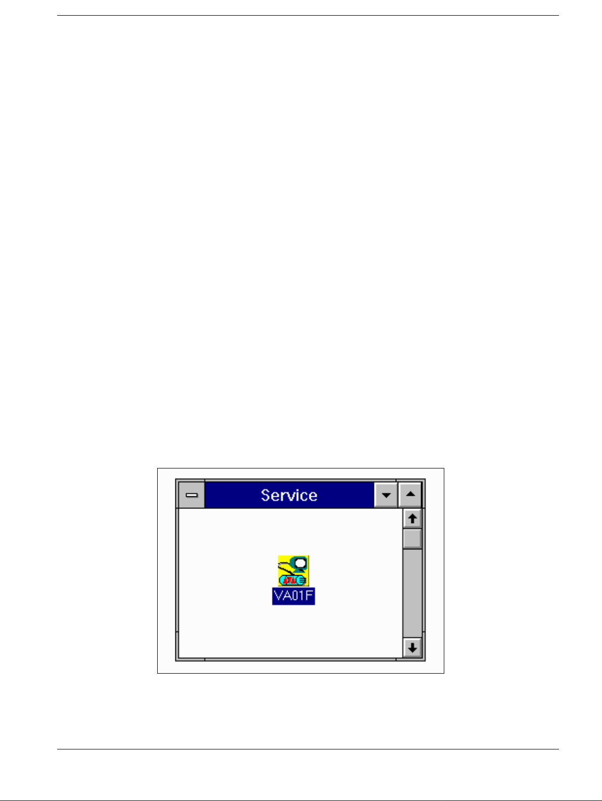
• Enter VA01F in the "Descript ion" field, select the "Symbol" box, con firm with "OK".
Start service program 2
• Connect the service PC ( Com1) with serial interface cable t o D12.X100.
• Start the service pr ogram by double clicking the icon (Fig. 1).
Fig. 1
Siemens AG TD AX 1 RX52-041.03 2.0 1 Register 4 VIDEOMED SX
Medical Engineering Rev. 05 03.96 Service
Page 8

Chapter 2Settings
Page 2 of 10
• Click "Service" or the service pr ogram will automatically start aft er approx. 10 seconds
(Fig.2).
Fig. 2
Selecting the Emulation 2
• Call the mask as shown in Fig.3 via <Conf iguration> <Emulation>.
• Select the required emulation f or VIDEOMED H1X or VIDEOMED HD and click "OK".
• Confirm the change of the emulation wi th "Permanent".
Fig. 3
VIDEOMED SX Register 4 RX52-041.032.01 TD AX 1 Siemens AG
Service Rev. 05 03.96 Medical Engineering
Page 9

Settings Chapter 2
Warning
Page 3 of 10
Selecting the Video Standard 2
• Call up <Configuration>< Video-Norm>.
• The selection of 1023/60Hz and 1249/50Hz are possible for the H1X/HD emulation .
Confirm the change of the Video standard wit h "OK" (Fig.4)..
• The standard 1125/60Hz is prep ared for future applications.
Fig. 4
If the Video standard has been changed, the size and position of
the image has to be newly adjusted.
Adjustment of the size and position of the image 2
The TV system should have been switched on for at least 15 minutes.
• Call <Adjustment> <Auto Adjustment>. Select only “Image Size” i n the window, as
shown in Fig.5. The other three possibi lities are not selected.
Fig. 5
Siemens AG TD AX 1 RX52-041.03 2.0 1 Register 4 VIDEOMED SX
Medical Engineering Rev. 05 03.96 Service
Page 10

Chapter 2Settings
Page 4 of 10
• Click "Adjust" and let it run through until the "finished" status appears. Save the data
with "Permanent".
• Quit the service program of VIDEOMED S.
• Switch off the system and, after approx. 10 seconds, switch it on again aft er the TV
system has been de-energized.
Setting the size of the AGC measurement fields 2
• Call up <Configuration>< Measuring area> and set the si ze of the measurement field
according to the table. Use "Send" to se nd values and "Permanent" to save them.
I.I. Type Zoom 0Zoom 1Zoom 2Zoom
3
40 cm 4.5 GU 6.0 GU 9.0 GU 11.0 GU
Fig. 6
33 cm 4.5 GU 6.0 GU 9.0 GU 11.0 GU
27/23 cm 6.0 GU 9.0 GU 11.0 GU n.a.
VIDEOMED SX Register 4 RX52-041.032.01 TD AX 1 Siemens AG
Service Rev. 05 03.96 Medical Engineering
Page 11

Settings Chapter 2
Page 5 of 10
Adjusting the fix gain 2 (only with Fluorospot H) 2
• SS OFF at the generator
• Connect oscilloscope to the TV central control unit D8.TP BAS1, or FLUOROSPOT H
Transition Panel TP6.
Ext. trigger to D10.X4 (V
• Create a folder, e.g. "Test", in the patient list on the FLUOROSPOT H and select
Acquisition (F4).
• Call up DR single or Dr series 0.5 f /s organ prgram.
• Call up <Configuration>< Video Amp> in the VIDEOMED S service software
• Select peak suppression with t he "Enable"box.
"none"appears in the "Peak Suppress" box (Fig.7).
• Select "Adjust" .
Note: No message is shown in the status li ne after "Adjust" is clicked.
• Quit the window with "Cancel".
pulse
).
Fig. 7
• Also quit the followin g mask with "Cancel". By doing so, t he adjustment is not made
permanent (Fig.8).
Siemens AG TD AX 1 RX52-041.03 2.0 1 Register 4 VIDEOMED SX
Medical Engineering Rev. 05 03.96 Service
Page 12

Chapter 2Settings
Page 6 of 10
Select
cancel
Fig. 8
• Call <Videoamplifier:Input and Processing> under <Diagnostic> (Fi g. 9).
With video amplifier D8 part No. 15 99 898
• Enter 2000 mV in the "Test Pattern" box and confirm with "Send".
With video amplifier D8 Part Np. 37 94 208
• Enter 1410mV in the "Test Pattern" box and confirm with " Send".
Fig. 9
VIDEOMED SX Register 4 RX52-041.032.01 TD AX 1 Siemens AG
Service Rev. 05 03.96 Medical Engineering
Page 13

Settings Chapter 2
Page 7 of 10
• Release DR single exposure on the uni t
• Measure the BA signal for manual 2 in the image and line center. Reference value U =
1250 ± 20 mV.
If the value is not obtained within the tolerance, proceed as follows:
• Call up <Configuration>< Video Amp> in the VIDEOMED S Service Program (Fig. 7).
• Increase or decreas e accordingly the adjustment for "Fix Gain 2" and adjust with
"Adjust".
• After each change release a f urther DR exposure with the square-wave signal .
• If the reference val ue is obtained, take over the adjustment with "Permanent".
• Call up again <Configura tion><Video Amp>, set the "Peak Suppress." to 800 mV
and select "Adjust".
• Release DR exposure with the te st signal.
• Measure the BA signal in the image and l ine center. Reference value U = 1050 ± 20 mV.
• If the value is not obtai ned, change the adjustment of the Peak Suppression
correspondingly.
• Once the reference value is obt ained, save the last adjustment with " Permanent".
Siemens AG TD AX 1 RX52-041.03 2.0 1 Register 4 VIDEOMED SX
Medical Engineering Rev. 05 03.96 Service
Page 14

Chapter 2Settings
Note
Page 8 of 10
Overview of the Configuration as H1X Emulation 2
• Call configuration via <Inf o><Configuration >and compare with the st ored settings.
• If necessary, change parameters acco rding to overview Fig.10 .
Fig. 10
The parameters for the image reversal must be determined
depending on the unit.
The settings may not be changed for: Videogain+max. beam-current, Gamma, Peak Suppr. and bias-light.
The values for Blanking-offset 1/2, Fix Gain 1/2, AGC mean and
Peak Suppr. are pre-settings and may be changed if necessary.
The desired values required can be taken from page 2-9 of the
present instructions.
VIDEOMED SX Register 4 RX52-041.032.01 TD AX 1 Siemens AG
Service Rev. 05 03.96 Medical Engineering
Page 15

Settings Chapter 2
NOTE
Page 9 of 10
Overview of the Configuration as HD Emulation 2
• Call configuration vi a <Info><Configuration> and compare wit h the stored settings.
• If necessary, change the parameters according to overview (Fi g.11).
Fig. 11
The parameters for the image reversal must be determined
depending on the unit.
Siemens AG TD AX 1 RX52-041.03 2.0 1 Register 4 VIDEOMED SX
Medical Engineering Rev. 05 03.96 Service
Page 16

Chapter 2Settings
Page 10 of 10
Nominal values for the H1X emulation 2
Pedestal 2
Operating mode BA-Signal
Manual gain 1 80 ± 10 mV (presetting)
Manual gain 2 50 ± 10 mV
Manual gain 1/2 2
With video amplifier D8 Part No. 15 99 898
TV CCU Manual gain 1 Manual gain 2
Input B-Signal = 2000mV B-Signal = 2000 mV
Output BA-Signal = 1100 mV
± 20 mV
With video amplifier D8 Part No. 37 94 208
BA-Signal = 1050 mV
± 20 = mV
TV CCU Manual gain 1 Manual gain 2
Input B-Signal = 1410mV B-Signal = 1410mV
Output BA-Signal = 1100 mV
± 20 mV
BA-Signal = 1050 mV
± 20 = mV
AGC function 2
BA- Signal with 2.1 mm CU (valid for all I.I.Formats)
Interlaced 350 mV ± 30 mV
Progressive 350 mV ± 30 mV
VIDEOMED SX Register 4 RX52-041.032.01 TD AX 1 Siemens AG
Service Rev. 05 03.96 Medical Engineering
Page 17

Service auxiliaries 3
Generating a Saw-Tooth 3
The grid signal generator can no longer be used with the VIDEOMED SX. In order to generate a saw-tooth (BA=1100 mV) at D8.BAS 1 which is necessary to set the Video Inboard of the FL-H, some setting parameters have to be changed.
• Select <Configur ation> <Video-Amp> in the service pr ogram of the VIDEOMED SX.
• First enter 1500 mV for Fix Gai n 1/2 and confirm the setting with "Adjust".
• Change the values as shown in the Vi deo Amplifier: Output window. Select "Adjust"
and let the video amplifier adjust itself (Fig.1).
• Quit the window with Cancel.
Chapter 3
Page 1 of 4
Fig. 1
• Do not accept the se ttings with "Permanent", but close t he mask with "Cancel" (Fig.2).
Select
Cancel
Fig. 2
Siemens AG TD AX 1 RX52-041.03 2.0 1 Register 4 VIDEOMED SX
Medical Engineering Rev. 05 03.96 Service
Page 18

Chapter 3Service auxiliaries
Page 2 of 4
• Connect oscilloscope to te st point D8.BAS 1
• Select on the generator deck an or gan program for DSA exposure (manual gain1) or f or
DR exposure (manual gain2) according to whether the B channel or the A channel of the
Video In board of the FL-H should be adjust ed.
• Create a folder, e.g. "T est" in the patient list of the FL -H via the function key F1 and
select Acquisition with F4.
• SS off
• Release an exposure or series without radiation with the exposure release s witch of the
unit.
• Call <Service Switches>under<Diagnostics>. Click DL EIN Simulation "on" , as
shown in Fig.3 and switch video channel through with "Send".
Fig. 3
• Call window under <Diagnostics><Videoamplif ier:Input and Processing>.
• Set values as shown below and confir m with "Send".
Start value for "Ramp" with vi deo amplifier D8 Part No. 15 99 898 is 1680 mV:
Start value for "Ramp" with vi deo amplifier D8 Part No. 37 94 208 is 1200 mV.
• Press precontact with the exposur e release switch of the unit, or with the f ootswitch,
release exposure.
• By changing the value "Ramp" (1800 mV), adjust a saw toot h signal BA=1100mV ±
10 mV, measured above the line in the middle of the image.
VIDEOMED SX Register 4 RX52-041.032.01 TD AX 1 Siemens AG
Service Rev. 05 03.96 Medical Engineering
Page 19

Service auxiliaries Chapter 3
Page 3 of 4
Fig. 4
• The settings for the FLUOROSPOT H are made accordi ng to the Camtronics Service
Manual 89999-0031.
•
• If the saw tooth signal i s not needed anymore, quit the “Video Amplifier : I nput”
window with "Cancel" .
• Select "Exit".
• The mask that follows has by all means t o be confirmed with "Reject" as otherwise
operational values usually set up ar e not reproduced anymore.
• Quit the VIDEOMED S service program.
• SS ON at the generator.
Siemens AG TD AX 1 RX52-041.03 2.0 1 Register 4 VIDEOMED SX
Medical Engineering Rev. 05 03.96 Service
Page 20

Chapter 3Service auxiliaries
Page 4 of 4
This page intentionally left blank.
VIDEOMED SX Register 4 RX52-041.032.01 TD AX 1 Siemens AG
Service Rev. 05 03.96 Medical Engineering
Page 21

Changes to previous version 4
Chapter 1
Page 1 "Validity of the document" section included.
"prerequisites" sectio n remo ved.
Chapter 2
Page 1 A sentence added in the "Start service program" section.
Page 6 Configurations for two different video amplifiers D8 included.
Page 9 Page break
Page 10 Additional table included in the "Nominal values for the HiX emulation"
section.
Chapter 3 Changed
Chapter 4 Changed
Chapter 4
Page 1 of 2
TDAX 7 / Seel
TDAX 1 / Biedermann
AUT 98 /Carver
Siemens AG TD AX 1 RX52-041.03 2.0 1 Register 4 VIDEOMED SX
Medical Engineering Rev. 02 03.96 Service
Page 22

Chapter 4Changes to prev ious version
Page 2 of 2
This page intentionally left blank.
VIDEOMED SX Register 4 RX52-041.032.01 TD AX 1 Siemens AG
Service Rev. 02 03.96 Medical Engineering
 Loading...