

Page 1

Automation– and Drive Technology- SCE
Training document for the company-wide
automation solution
Totally Integrated Automation (T I A)
MODULE B4
Data blocks
T I A Training document Page 1 of 18 Module B4
Last revision: 02/2002 Data Blocks
Page 2

Automation– and Drive Technology- SCE
This document was provided by Siemens A&D SCE (automation and drive technology, Siemens A&D
Cooperates with Education) for training purposes. Siemens does not make any type of guarantee regarding its
contents.
The passing on or duplication of this document, including the use and report of its contents, is only permitted
within public and training facilities.
Exceptions require written permission by Siemens A&D SCE (Mr. Knust: E-Mail:
michael.knust@hvr.siemens.de). Offences are subject to possible payment for damages caused. All rights are
reserved for translation and any case of patenting or GM entry.
We thank the company Michael Dziallas Engineering and the instructors of vocational schools as well as further
persons for the support with the production of the document.
T I A Training document Page 2 of 18 Module B4
Last revision: 02/2002 Data Blocks
Page 3
Automation– and Drive Technology- SCE
PAGE:
1. Forward................................................................................................................. 4
2. Notes for Data Blocks.......................................................................................... 6
3. Generating Data Blocks ...................................................................................... 7
The following symbols stand for the specified modules:
Information
Programming
Example exercise
Notes
T I A Training document Page 3 of 18 Module B4
Last revision: 02/2002 Data Blocks
Page 4
Automation– and Drive Technology- SCE
1. FORWARD
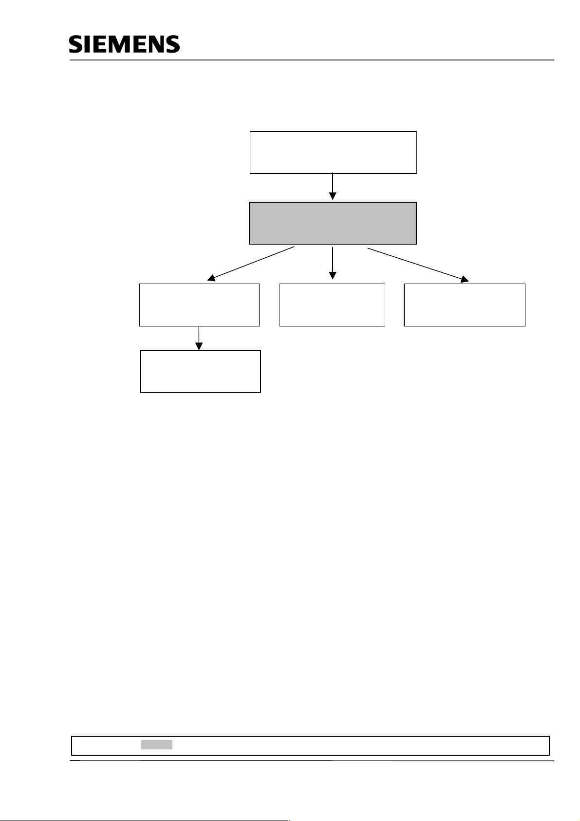
The module B4 is assigned content wise to Additional functions of STEP 7- Programming.
STEP 7- Programming
2 - 3 days A modules
Basics of
Additional functions of
STEP 7- Programming
2- 3 days B Modules
Industrial field bus
systems
2- 3 days D modules
Sequencer
programming
2- 3 days C modules
Process
visualization
2- 3 days F modules
IT- Communication
with SIMATIC S7
1- 2 days E modules
Learning goal:
In this module, the reader should learn how a data block can be used to save data.
· Generating data blocks
· Specifying a structure of a data block
· Access to a data element in a STEP 7- Program
Requirements:
For the successful use of this module, the following knowledge is assumed:
· Knowledge in the use of Windows 95/98/2000/ME/NT4.0
· Basics of PLC- Programming with STEP 7 (e.g. Module A3 - ‘Startup’
PLC programming with STEP 7)
· Basics to structured programming (e.g. Appendix I - Basics to PLC –Programming with
SIMATIC S7-300)
Forward Notes Generating data blocks
T I A Training document Page 4 of 18 Module B4
Last revision: 02/2002 Data blocks
Page 5
Automation– and Drive Technology- SCE
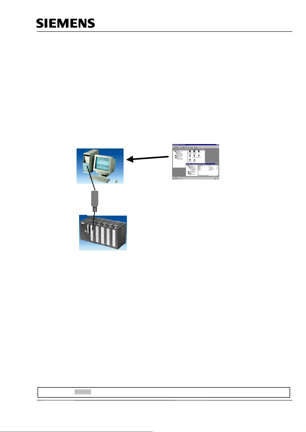
Required hardware and software
1 PC, Operating system Windows 95/98/2000/ME/NT4.0 with
- Minimal: 133MHz and 64MB RAM, approx. 65 MB free hard disk space
- Optimal: 500MHz and 128MB RAM, approx. 65 MB free hard disk space
2 Software STEP 7 V 5.x
3 MPI- Interface for the PC (e.g. PC- Adapter)
4 PLC SIMATIC S7-300 with at least one digital in- and output module. The inputs must be lead
through a functional unit.
Example configuration:
- Power supply: PS 307 2A
- CPU: CPU 314
- Digital input: DI 16x DC24V
- Digital output: DO 16x DC24V / 0.5 A
1 PC
2 STEP 7
3 PC Adapter
4 SIMATIC S7-300
Forward Notes Generating data blocks
T I A Training document Page 5 of 18 Module B4
Last revision: 02/2002 Data blocks
Page 6
Automation– and Drive Technology- SCE
2. NOTES FOR DATA BLOCKS
Data Blocks (DBs) can be used by your program to save data in the CPU. Your hard disk contains up
to 8 KBytes ( 8192 Bytes ) space.
There are two types of data blocks. Global DBs, where all OBs, FBs and FCs read all saved data or
can even write in the DB and local instance DBs, which are assigned a particular FB.
In the DBs, different data types (e.g. BOOL or WORD ) can be saved in arbitrary order.
This structuring of a DB follows through input in a table with the tool
LAD, STL,FBD - S7 Block Programming .
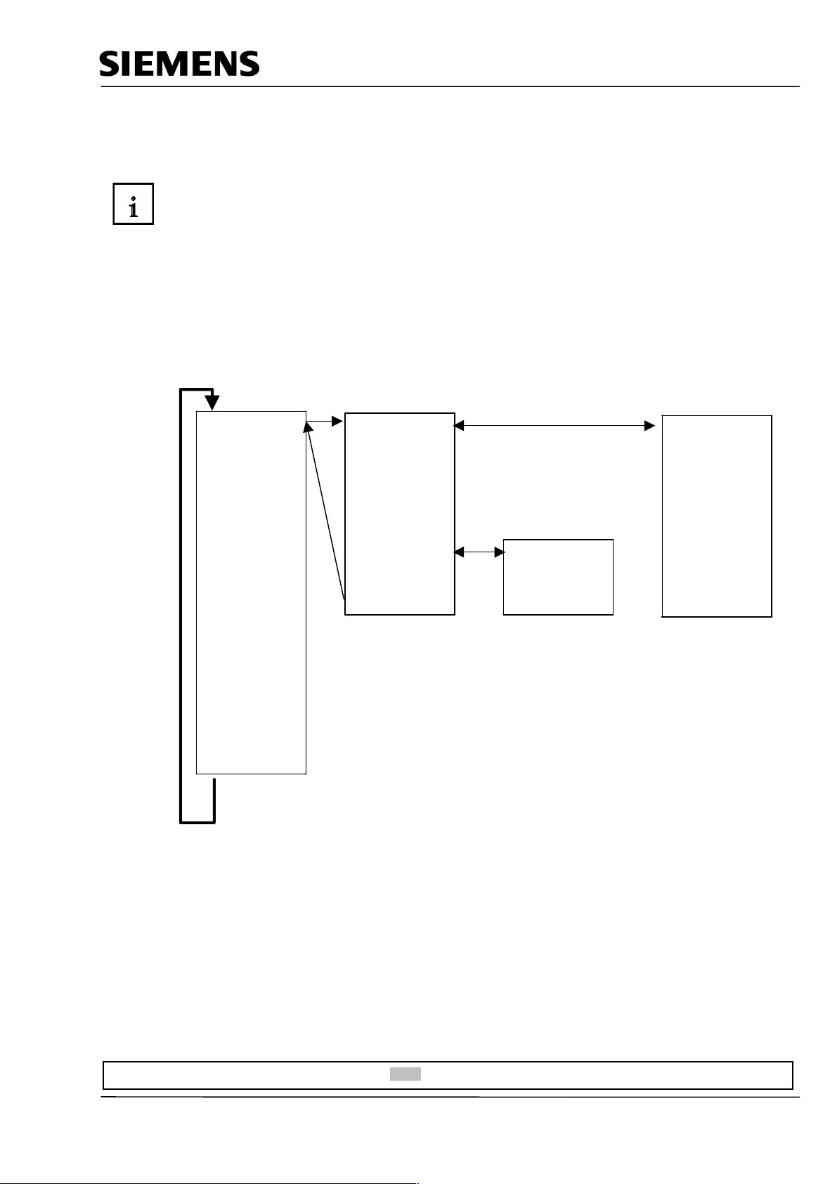
In the program structure from STEP 7, data blocks are found as follows:
OB 1
Call FB1, DB10
UC FC2
L DB11.DBW0
BE
DB 11DB 10FB 1
Global DB
For all
FBs
FCs
OBs
Instance DB
Local data only
FB1
OB = Organization Block
FB = Function Block
FC = Function
DB = Data Block
Forward Notes Generating data blocks
T I A Training document Page 6 of 18 Module B4
Last revision: 02/2002 Data block
Page 7

Automation– and Drive Technology- SCE
3. GENERATING DATA BLOCKS
Data blocks are generated and opened like program blocks in the tool LAD,STL,FBD: Program
blocks. They serve e.g. for the saving of data and system states.
In the following text, the generation of a simple example is described by the use of a global data
block:
Thereby values should be chosen with the switches 'S0' to 'S7' and displayed on an output module
‘Display‘. Thereby one has more switches by activation, where the representation of the value to
switch S7 has the highest priority and the representation of the value to switch S1 has the lowest.
The example relates to the displayed addresses below:
Inputs:
- Switch S0 = I 0.0
- Switch S1 = I 0.1
- Switch S2 = I 0.2
- Switch S3 = I 0.3
- Switch S4 = I 0.4
- Switch S5 = I 0.5
- Switch S6 = I 0.6
- Switch S7 = I 0.7
Outputs:
- Display = QW4
Forward Notes Generating data blocks
T I A Training document Page 7 of 18 Module B4
Last revision: 02/2002 Data blocks
Page 8

Automation– and Drive Technology- SCE
In order to generate this program example, the following steps must be followed (Thereby the
program is dispensed with the creation of the hardware configuration):
1. Call SIMATIC Manager with a double click ( ® SIMATIC Manager)
2. Create a new project ( ® File ® New)
Forward Notes Generating data blocks
T I A Training document Page 8 of 18 Module B4
Last revision: 02/2002 Data blocks
Page 9

Automation– and Drive Technology- SCE
3. In the name path, create the project with the name Testproject_DB.
(® ’Testproject_DB’ ® OK)
4. Insert a new S7-Program ( ® Insert ® Program ® S7-Program).
Forward Notes Generating data blocks
T I A Training document Page 9 of 18 Module B4
Last revision: 02/2002 Data blocks
Page 10

Automation– and Drive Technology- SCE
5. Highlight the folder Blocks. (® Blocks)
6. Insert Data Block ( ® Insert ® S7 Block ® Data Block).
Forward Notes Generating data blocks
T I A Training document Page 10 of 18 Module B4
Last revision: 02/2002 Data blocks
Page 11

Automation– and Drive Technology- SCE
7. Enter the number DB10 for the data block and accept with OK (® DB10 ® OK).
8. Open the data block DB10 with a double click(® DB10).
Forward Notes Generating data blocks
T I A Training document Page 11 of 18 Module B4
Last revision: 02/2002 Data blocks
Page 12

Automation– and Drive Technology- SCE
9. Acknowledge the type of data block. ( ® Data Block ® OK )
Note: Data blocks with an assigned FB are automatically displayed by the call of your
associated FB. It makes no sense to create this alone. Data blocks with assigned user
defined data types (UDT) are data blocks, whose structure was already assigned in this
UDT.
Forward Notes Generating data blocks
T I A Training document Page 12 of 18 Module B4
Last revision: 02/2002 Data blocks
Page 13

Automation– and Drive Technology- SCE
10. The Data Block is generated with a symbol Name. The Type, an Initial value as well as a
Comment (optional) are entered.
The address is automatically generated and cannot be altered.
The data block can be saved
PLC must be on STOP! (® Name® Type ® Initial value ® Comment ®
and downloaded into the PLC . The mode switch on the
® )
The absolute address is created from
STEP 7, when the DB is compiled or
saved.
The address format is BYTE, BIT.
Over this address, the data elements can
also be accessed. (e.g. over downloadand compile operations or in logical
operations.).
Symbolic name
which is referenced
to the absolute
address.
Desired data
type (see below)
for your data
element.
Initial value , to which
the data type must be
compatible ( optional ).
Comment for
documentation
( optional ).
Note: If the data block is assigned as a local instance DB to a FB, the declarations table of the
FB declares the structure of the DB.
Forward Notes Generating data blocks
T I A Training document Page 13 of 18 Module B4
Last revision: 02/2002 Data blocks
Page 14

Automation– and Drive Technology- SCE
Data in a data block must be determined through data types.
The following standard- data types are defined in the S7 below :
Type and
description
BOOL (Bit) 1 Boolean text TRUE/FALSE TRUE
BYTE (Byte) 8 Hexadecimal
WORD (Word) 16 Binary number 2#0 to 2#1111_1111_1111_1111 2#0001_0000_0000_0000
Hexadecimal
BCD C#0 to C#999 C#998
Decimal number
DWORD (Double
word)
Hexadecimal
Decimal number
INT (Integer) 16 Decimal number
DINT (Int,32 bit) 32 Decimal number
REAL (Floatingpoint number)
S5TIME
(Simatic-Time)
TIME
(IEC-Date)
DATE
(IEC-Date)
TIME_OF_DAY
(Time)
CHAR (Character) 8 ASCII-Characters ´A´, ´B´ etc. ´B´
Size
Format-Options Range and number notation
in Bits
number
number
unsigned
32 Binary number 2#0 to
number
unsigned
signed
signed
32 IEEE floating-point
number
16 S7-Time in steps of
10 ms
32 IEC-Time in steps
from 1ms, integer
signed
16 IEC-Date in steps
of 1 day
32 Time in steps of
1ms
Example
(lowest to highest values)
B#16#0 to B#16#FF B#16#10
W#16#0 to W#16#FFFF W#16#1000
B#(0,0) to B#(255,255) B#(10,20)
2#1111_1111_1111_1111_1111_1111
_1111_1111
DW#16#0000_0000 to
DW#16#FFFF_FFFF
B#(0,0,0,0) to B#(255,255,255,255) B#(1,14,100,120)
-32768 to 32767 1
L#-2147483648 to L#2147483647 L#1
Upper limit: +/-3.402823e+38
Lower limit: +/-1.175495e-38
S5T#0H_0M_0S_10MS to
S5T#2H_46M_30S_0MS and
S5T#0H_0M_0S_0MS
-T#24D_20H_31M_23S_648MS to
T#24D_20H_31M_23S_647MS
D#1990-1-1 to D#2168-12-31 DATE#1994-3-15
TOD#0:0:0.0 to TOD#23:59:59.999 TIME_OF_DAY#1:10:3.3
2#1000_0001_0001_1000_1
011_1011_0111_1111
DW#16#00A2_1234
1.234567e+13
S5T#0H_1M_0S_0MS
S5TIME#1H_1M_0S_0MS
T#0D_1H_1M_0S_0MS
TIME#0D_1H_1M_0S_0MS
Forward Notes Generating data blocks
T I A Training document Page 14 of 18 Module B4
Last revision: 02/2002 Data blocks
Page 15

Automation– and Drive Technology- SCE
11. Values should be modified in a data block. It is not adequate to modify them in the field Initial
value . This is only possible, when one switches to the Data View under View ( ® View ® Data
View).
12. Now a new value can be entered in the field Actual value and saved onto the hard drive with
as well as downloaded into the CPU with ( ® Actual value ® ® ).
Forward Notes Generating data blocks
T I A Training document Page 15 of 18 Module B4
Last revision: 02/2002 Data blocks
Page 16

Automation– and Drive Technology- SCE
13. In order to generate the program with the accessible data elements, the OB1 must be opened
through a double click in SIMATIC Manager ( ® SIMATIC Manager ® OB1).
14. Then accept the setting with OK (® OK ).
Forward Notes Generating data blocks
T I A Training document Page 16 of 18 Module B4
Last revision: 02/2002 Data blocks
Page 17

Automation– and Drive Technology- SCE
There are three possibilities to access the data:
1. Direct address access:
One can access one data element in a data block with the following instructions:
Example:
L DB 20. DBB2 Load data byte 2 from DB20 into ACCU 1
L DB 22. DBW4 Load data word 4 from DB22 into ACCU 1
A DB 2. DBX5.6 Carry out an AND- logical operation with data bit 5.6 from DB2.
2. Access to the data elements in the already opened data blocks:
In order to be able to access a data element over several data elements, the DB must first be opened
with the instructions OPN DB or OPN DI. Then several data bits (DBX/DIX),data bytes (DBB/DIB),
data words (DBW/DIW) or data double words (DBD/DID) can be processed in digital or binary
operations.
In doing so, one especially uses OPN DI for the opening of instance DBs. It can also be used for
global DBs, when 2 DBs remain open at the same time.
Example:
OPN DB 20 Opening of DB20
OPN DI 22 Opening of DB22
L DBW 0 Download data word 0 from DB20 into AKKU 1
T MW 1 Transfer the contents from ACCU 1 to memory bit 1
A DIX 0.0 AND- Operation from data bit 0.0 to DB22 with
A I 1.0 input bit 1.0
= Q 4.0 Assignment of the result to output bit 4.0
3. Access to data out of local instance DBs by call with the function block:
Data can be transferred by the call of the corresponding instance data block with the instruction CALL
FB1, DB19. The assignment of the variables that would be defined in the declarations table of the FB
and whose value stands in the DB, take place directly in the absolute address (e.g. IW0, M 10.0 or
QW4) with the CALL instruction.
Example:
CALL FB1, DB19
COUNT:= IW 0 The variable COUNT is assigned to IW 0 as an absolute address.
OUT:= Q 4.0 The variable OUT is assigned to Q4.0 as an absolute address.
Note: The format of the variables and the assigned absolute address must be equal.
Forward Notes Generating data blocks
T I A Training document Page 17 of 18 Module B4
Last revision: 02/2002 Data blocks
Page 18

Automation– and Drive Technology- SCE
15. With LAD, STL, FBD: Program blocks, you now have an editor that give you the possibility to
generate your STEP 7-Program.
The schema for the selection of the data element through the button is shown for the first three
inputs as specified below.
If the organization block OB1 is not generated for all switches S0 to S7, it should be saved
and downloaded into the PLC
. The mode switch of the CPU must be on STOP! ( ® ®
)
16. Through the switching of the key switch to RUN, the program is started.
If only one of buttons S0 to S7 is activated through inching, the display of the value in the data
block that is assigned takes place on the output module with the address QW4.
Forward Notes Generating data blocks
T I A Training document Page 18 of 18 Module B4
Last revision: 02/2002 Data blocks
 Loading...