

Page 1
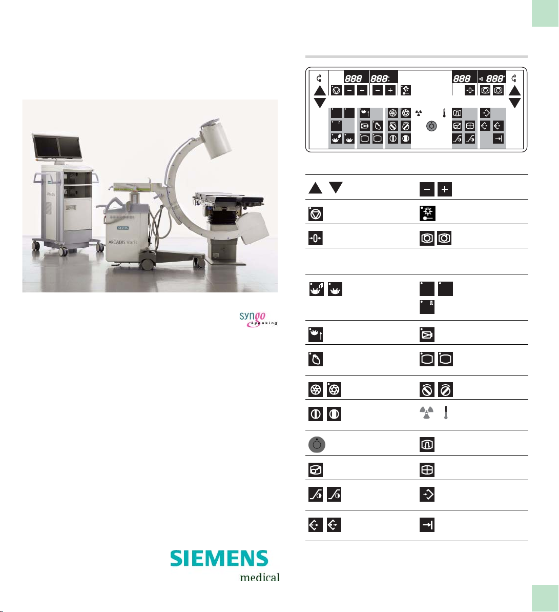
C-arm keyboard
kV
mAs
mA min
ARCADIS Varic
VB 13C
Quick Guide
ROAD
SUB
MAP
mA
DR
R
top/lateral row of keys
Lift/lower
C-arm
Switch ADR stop
on/off
Reset f luoroscopy
time
bottom row of keys
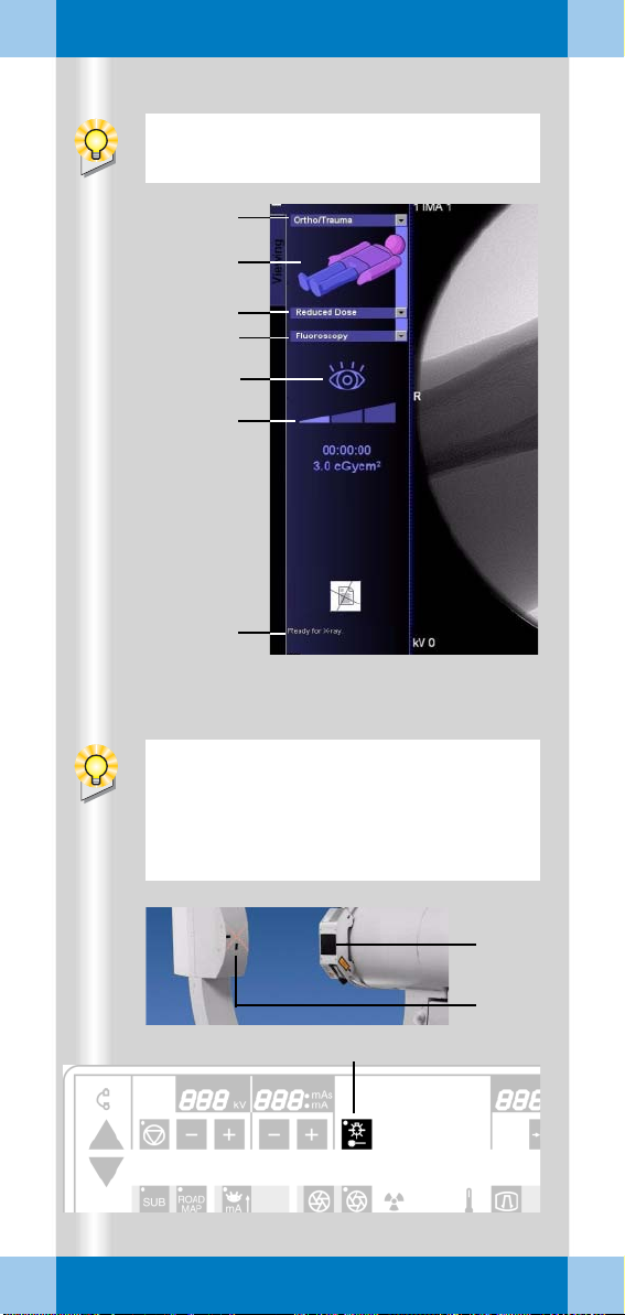
Operating modes:
-Pulsed
fluoroscopy
- Continuous
fluoroscopy
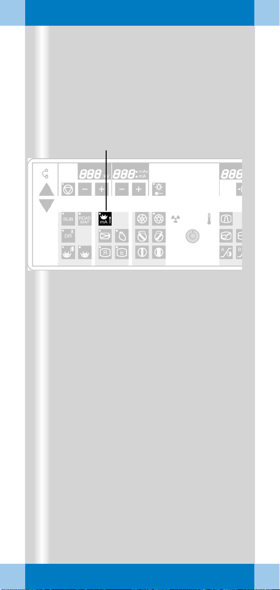
mA
Powe r m od e Enlarge live image
Noise reduction Image reversal
Open/close
iris diap hragm
Open/close
slot
diaphragm
System OF F Edge enhance-
A
B
R
B B
BA
Reduce/increase
kV and mA
Single-tank
laser light localizer
Rotate image
SUB
DR
R
- Subtraction
MAP
-Roadmap
-Digital
radiography
R
left/right o r
top/bottom
Rotate slot
diaphragm
Radiation indicator
Tube unit temperature
Operating modes:
ROAD
ment
A B
B
Enlarge stored
images
Contrast adjustment left/rig ht
monitor
Read images from
B
memory forward/
backward
Monitor split
horizontal/vertical
A
B
Save im age
Print image
Page 2
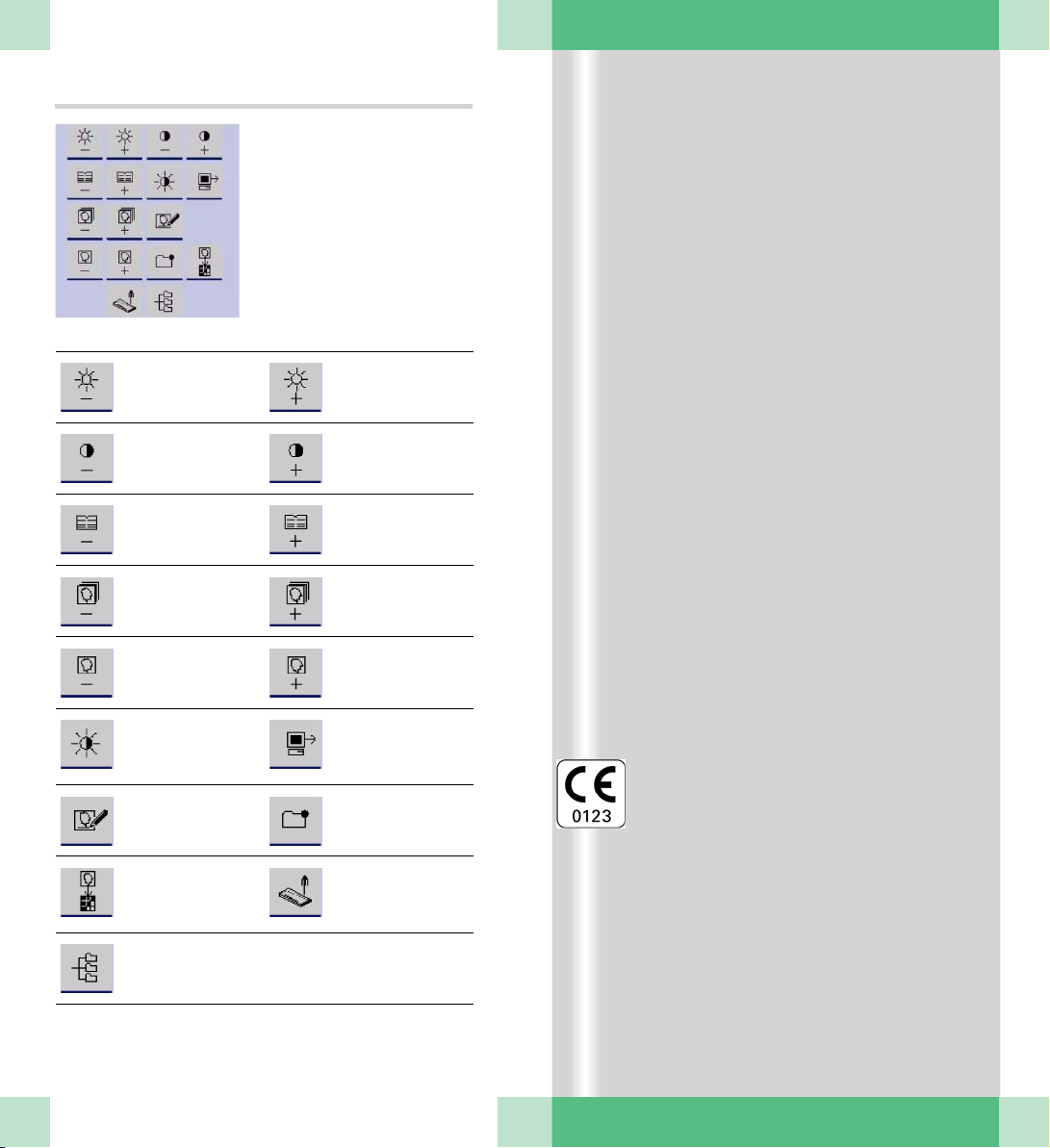
Monitor trolley symbol keypad
Brightne ss - Brightness +
Contrast - Contrast +
Scroll study back Scroll study
Scroll series back Scroll s eries
Scroll image back Scroll image
Switch between
negative and
positive image
Enter a study
comment
Copy to film sheet Call up Patient
Call up the
Patien t
Browser
for ward
for ward
for ward
Send to node 1
Mark an image
Registration
This product is provided with a CE marking in
according with the regulations stated in
Directive 93/42/EEC of June 14th, 1993 con
cerning medical devices.
The CE marking applies only to medical
devices which have been put on the market
according to the above-mentioned EC Direc
tive.
The original language of this document is
German.
This Quick Guide is available in German,
English, French, Italian and Spanish.
ARCADIS Varic Quick Guide
Page 3

Introduction
We welcome you as a user of the powerful
ARCADIS Varic C-arm system from Siemens.
This clearly laid out Quick Guide is intended
to guide you through the operation of the sys
tem.
The Quick Guide is valid only in conjunction
with the Operator Manuals and the safety
information they contain:
❏ Please observe the Operator Manual
and all supplements/addenda
❏ Please observe all safety information
The right-hand pages contain step-by-step
instructions corresponding to the typical
workflow in the OR.
The pages to the left contain illustrations and
and supplemental notes.
The description focuses on easy and fast
operation of the ARCADIS Varic from startup
through to shutdown of the system including
optional functions such as connection to a
hospital network or subtraction.
More detailed and complete descriptions can
be found in the ARCADIS Varic Operator
Manual.
-
ARCADIS Varic Quick Guide
3
Page 4

Table of Contents
Basics
Input devices ........................................ 7
syngo user interface ............................. 9
syngo control elements ...................... 11
Product overview
C-arm system ..................................... 13
Monitor trolley ..................................... 17
Examination procedure
Preparing the system ......................... 19
Patient registration ............................. 21
Preparation in the Examination
task card ............................................ 23
Radiation release and dose display .... 25
High-contrast fluoroscopy
(Power Mode) .................................... 29
Image rotation and reversal ................ 31
Collimator setting ............................... 33
Changing the contrast ........................ 35
Saving images .................................... 37
Fluoro Loop/LSH (option) ................... 39
Ending the examination ..................... 39
4
Subtraction and Roadmap
Performing a subtraction scene ......... 41
Postprocessing a subtraction scene .... 43
Roadmap ............................................ 51
Postprocessing
Loading patient images into the
Viewing task card ............................... 53
Image display ..................................... 55
Measuring and annotations ................ 57
Image manipulation ............................ 61
ARCADIS Varic Quick Guide
Page 5

Documentation
Printing ............................................... 65
Burning CDs ....................................... 75
Reports
Generating reports ............................. 77
Editing a LithoReport ......................... 79
Printing and exporting a report ........... 81
Connectivity
Send/Storage Commitment ............... 87
Get Worklist ....................................... 91
MPPS – Modality Performed
Procedure Step .................................. 93
Query/Retrieve ................................... 95
NaviLink 2D
Features ............................................. 97
Procedure ........................................... 97
Dismantling
Transport position ............................. 101
Switching off ..................................... 101
Cassette exposure (option)
Components .................................... 10 3
Preparing the exposure .................... 10 5
Exposure .......................................... 107
5
ARCADIS Varic Quick Guide
Page 6
Basics
This chapter is addressed to syngo beginners and users with little computer experience.
(1) (2) (3)
(4)
(5)
Functions of the symbol keypad see foldout cover.
ARCADIS Varic Quick Guide
(6)
(7)
6
Page 7

Basics
This chapter provides you with basic information on the input devices of the computer at
the monitor trolley and on the syngo user
interface.
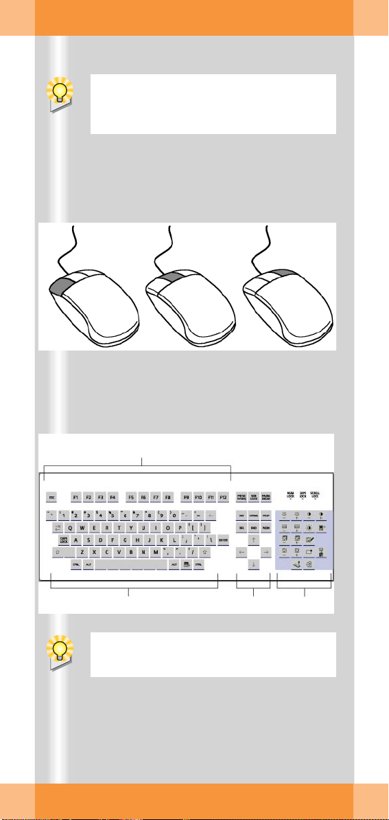
Input devices
The mouse
(1) Left button
Single click: select/mark
Double click: load data/program
Button kept pressed: drag/move
(2) Middle button
Button kept pressed: windowing
(change
(3) Right button
Single click: call up popup menu
(context-sensitive)
brightness and contrast)
The keyboard
(4) Function keys
F1 = syngo Online Help
(5) Alphanumeric keypad
Text input, e.g. patient data
(6) Cursor keypad
Movement of the mouse pointer in texts
(7) Symbol keypad
Direct selection of important syngo functions (e.g. calling up Patient Registration
or local database; image postprocessing
functions)
ARCADIS Varic Quick Guide
7
Page 8
Basics
(1)
(2)
(3)
(4)
After the ARCADIS Varic system has been
switched on, the syngo user interface auto
matically appears on the monitor trolley
screens.
-
(5) (6)
(7)
(8)
(9)
ARCADIS Varic Quick Guide
8
Page 9

Basics
syngo user interface
syngo consists of several stacked task cards.
These are assigned to the individual steps of
the workflow.
Ta s k c a rd s
(1) Menu bar
Calling up of main menus and submenus
(2) Tabs
Selection/switching of task cards
(3) Stack of subtask cards
Selection of processing tools and display
functions
Switching of subtask card via tab
(4) Status bar
Display of system messages
(5) Control area
Display of image and examination parameters, selection of functions (via subtask
cards)
(6) Image area
Display and processing of images
Windows/Dialogs
Windows are called up separately or displayed automatically.
Windows can be closed again after processing.
(7) Title bar
Name of window, "Close window" button
(8) Window content
Input and selection of data
(9) Softkeys/buttons
Confirmation or cancellation of actions
and messages
ARCADIS Varic Quick Guide
9
Page 10

Basics
(1) (2)
(3) (5)(4)
10
ARCADIS Varic Quick Guide
(6) (7)
(8) (10)(9)
Page 11

Basics
syngo control elements
Control elements on the screen are easiest
selected with the mouse.
Menus
(1) Main menu
Opens by pressing left mouse button
(2) Popup menu
Opens by pressing right mouse button
The content depends on the mouse
position ("mouse focus") on the screen
Input elements
(3) Text input field
(4) Selection list
Selection of preset parameters and data;
opens via arrow
(5) Spin box
Setting of values with arrow keys
(6) Radio buttons
Only one option selectable
(7) Check box
Several options selectable
Icon buttons
(8) Dimmed
Function not selectable
(9) Inactive
Function selectable, but not active
(10) Active
Function activated
ARCADIS Varic Quick Guide
11
Page 12
Product overview
(5)
(6)
(7)
As soon as you press the emergency stop
button, motorized up and down movement
of the C-arm system is disabled.
(4)
(1)
(2)
(3)
(4)
12
(6)
S
O
T
P
ARCADIS Varic Quick Guide
S
O
T
P
Page 13

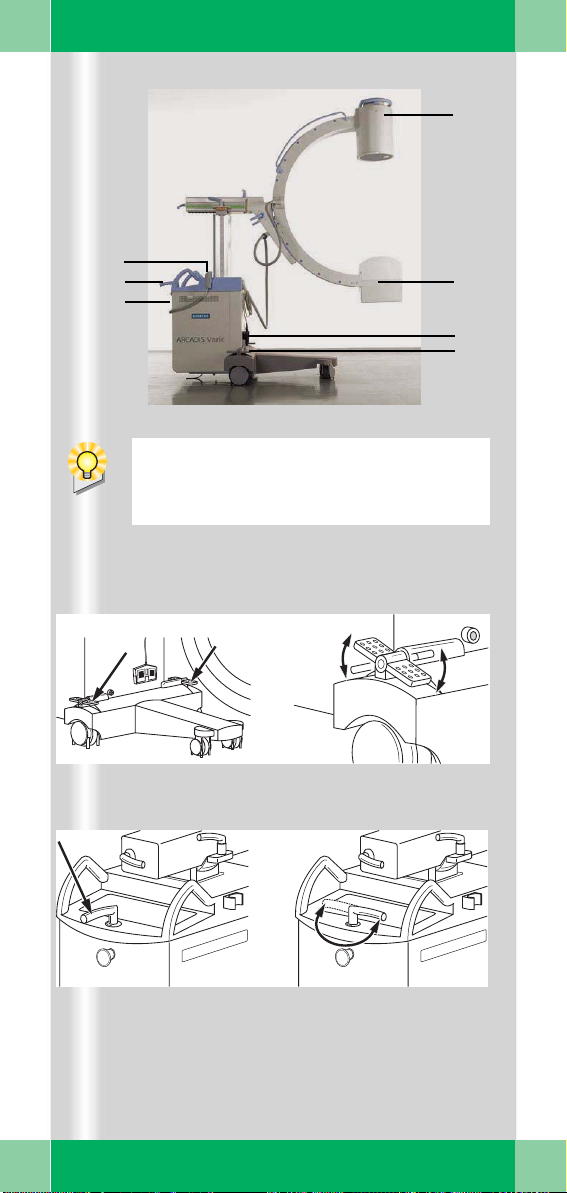
Product overview
C-arm system
C-arm
(1) Image intensifier
(2) X-ray tube
(3) Holder for footswitch
(4) Locking brake
(5) Hand switch
(6) Steering lever
(7) Emergency stop button
Brakes, steering lever
(4) Locking brake
❏ Locking brake released in center position:
Move C-arm system
(6) Steering lever
❏ Steering lever straight:
Move C-arm system in any direction
❏ Steering lever crosswise:
Move C-arm system in transverse direction, e.g. parallel to the table
ARCADIS Varic Quick Guide
13
Page 14
Product overview
(1)
130°
S
T
O
P
45cm
(2)
(3)
(4)
(5)
130°
S
T
O
P
ST
O
P
S
T
O
P
190°
190°
cm
20
12,5°
12,5°
14
ARCADIS Varic Quick Guide
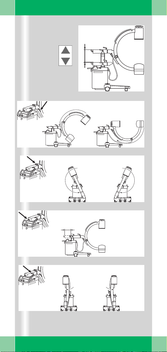
Page 15

Product overview
Moving the C-arm system
(1) Vertical travel (motorized)
Lift and lower C-arm
up to 45 cm
(2) Orbital movement
Change between a.p. and lateral position
➭ Starting from the a.p. position vertical to
-
40° and horizontal to + 90°
(130° in total).
(3) Angulation
Rotate C-arm about support arm in
vertical plane
by up to 190° in both directions
(4) Horizontal travel
Move C-arm horizontally
up to 20 cm
➭ Ideal for fine adjustments directly at the
OR-table.
(5) Swivel
Swivel C-arm about unit column in
horizontal plane
by up to 12.5° in each direction
➭ Ideal for fine adjustments directly at the
OR-table.
ARCADIS Varic Quick Guide
15
Page 16

Product overview
(1)
(2)
(3)
(4)
(5)
(6)
16
ARCADIS Varic Quick Guide
Description of keyboard see Basics chapter.
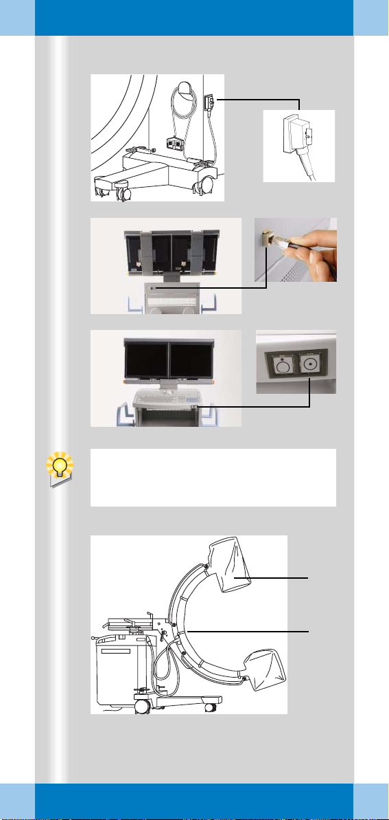
Page 17

Product overview
Monitor trolley
(1) TFT flat screen monitors
(2) Keyboard
(3) Power on/off switch
(4) CD drive
(5) Direction locks on the back wheels
(6) Brakes on the front wheels
ARCADIS Varic Quick Guide
17
Page 18
Examination procedure
(1)
(2)
(3)
18
If an additional access control mechanism
is configured for the system, you have to
log in with your name and password.
(4)
(5)
ARCADIS Varic Quick Guide
Page 19

Examination procedure
Preparing the system
Connecting, switching on and booting
✧ Connect the monitor trolley connecting
cable to the C-arm system (1).
✧ If available, connect the network cable
(if
the system is connected to an information system or a navigation system or network printer) (2).
✧ Plug the power plug into the power outlet.
✧ Switch on the C-arm system at the moni-
tor trolley (3).
➭ The system boots.
Covering the C-arm with sterile covers
✧ If necessary, cover the C-arm, e.g. with
the two-part sterile cover (4).
✧ Attach the cover with the sterilizable
clamps (5).
ARCADIS Varic Quick Guide
19
Page 20
Examination procedure
During operation, the window
can be opened by pressing the
Patient Registration icon button
on the monitor trolley.
(1)
20
ARCADIS Varic Quick Guide
(2)
(3)
Page 21

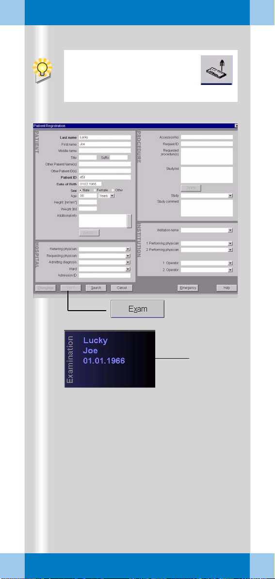
Examination procedure
Patient registration
First, the Patient Registration window (1)
appears directly.
(Here: maximal configuration)
✧ Enter the patient data into this mask (1).
At a minimum, the bold fields must be filled
out.
✧ Using the mouse, click on the Exam (2)
button.
➭ The patient data appear in the
Examination task card (3).
➭ The unit is now ready to start an examina-
tion.
Alternatives
❏ Preregistration/Scheduler
The patient has already been registered in the
Scheduler, from where it can be loaded into
the Patient Registration card.
❏ Emergency
If the patient data are unknown, the patient is
assigned a provisional number consisting of
the date and the time of the entry. These data
can later be corrected.
❏ Search
If an information network (e.g. hospital network) is connected, you can start a search for
registered patients here.
ARCADIS Varic Quick Guide
21
Page 22
Examination procedure
To select parameters, use the mouse to
click the monitor trolley.
(1)
(2)
(3)
(5)
(6)
(4)
ARCADIS Varic Quick Guide
(7)
If the optional laser light localizer is available, the object should be positioned with
the laser light localizer, i.e. without radia
tion, as far as possible for reasons of radiation protection.
(10)
-
(8)
(9)
22
Page 23

Examination procedure
Preparation in the Examination task card
✧ Select the medical application area (1).
✧ Select the body region by clicking the
VPA
(Virtual Patient Anatomy) (2).
✧ Select the required application program (3).
➭ With the application program you simulta-
neously select a dose level (reduced,
standard, increased). This is shown by a
bar (4).
✧ Select the desired operating mode (5).
Alternative: Select/switch operating
mode on the C-arm keyboard (see fold-out
cover).
➭ The selected operating mode is shown as
a symbol (6).
➭ The readiness of the C-arm is shown in
the status bar (7).
Setting with the laser light localizer
Depending on the equipment, the l.I. side or
the I.I. integrated laser light localizer is avail
able next to the tube-side laser light localizer.
✧ Laser localizer on the I.I. side:
Press the button on the laser light localizer
to turn it on and off (8).
✧ Tube-side (9) and I.I. integrated laser light
localizer:
Press the button on the C-arm system (10)
to turn it on and off.
-
ARCADIS Varic Quick Guide
23
Page 24
Examination procedure
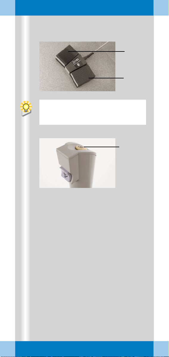
Exception: If the continuous fluoroscopy
mode is set, pressing the left footswitch
releases a single exposure.
(2)
(1)
(3)
24
ARCADIS Varic Quick Guide
Page 25

Examination procedure
Radiation release and dose display
Radiation release with the footswitch
✧ Actuate the right footswitch to release
continuous fluoroscopy (1).
✧ Actuate the left footswitch to release the
set operating mode (2).
Radiation release with the hand switch
✧ Press the release button to release the
set operating mode (3).
ARCADIS Varic Quick Guide
25
Page 26

Examination procedure
)
1
(
(4)
ADR stop is recommended, for example,
for
❏ Thin objects, e.g. w rist (the movement
causes the object to slide out of the
central beam, the image is underex
posed)
❏ Metal (high density of the metal leads
to strong overexposure)
❏ Transition between thoracic and lumbar
spine (movement of the diaphragm/mid
riff causes changes in the exposure).
(2)
(3)
-
-
26
ARCADIS Varic Quick Guide
(5)(6) (7)
Page 27

Examination procedure
Radiation time and dose display
(1) Display of accumulated fluoroscopic time
at the C-arm system
(2) Display of accumulated fluoroscopic time
at the monitor trolley (Examination task
card)
(3) Display of accumulated dose at the moni-
tor trolley (with optional dose measuring
chamber)
Alternative: Display of air kerma values
(preceding item: accumulated air kerma).
➭ After every five minutes of radiation, an
audible alarm sounds at the C-arm sys
tem.
✧ To temporarily deactivate the warning sig-
nal, press the Reset fluoro time button
on the C-arm system (4).
ADR stop, manual input of radiation parameters
All exposures are taken with automatic exposure control. This rule is turned off using
ADR
stop. The kV values can then be
selected manually.
-
✧ Select ADR stop at (5).
✧ If required, set a manual value with the
+/- buttons (6).
➭ kV and mA values are shown on the dis-
play at the C-arm system (7).
➭ As long as ADR stop is activated, the
manually set value remains unchanged.
ARCADIS Varic Quick Guide
27
Page 28
Examination procedure
(1)
28
ARCADIS Varic Quick Guide
Page 29

Examination procedure
High-contrast fluoroscopy (Power Mode)
Power Mode is an additional function that
can be selected for the fluoroscopy mode.
With Power Mode a higher contrast is
achieved, but with a higher dose.
✧ Select the Power Mode function at the
C-arm system (1).
➭ If the Power Mode function is activated,
a continuous warning signal sounds dur
ing fluoroscopy.
➭ The duration of the Power Mode function
is limited to 15
s.
-
ARCADIS Varic Quick Guide
29
Page 30
Examination procedure
The rotation is performed without radiation
and can be observed on the monitor.
(3)
(4)
(1) (2)
30
ARCADIS Varic Quick Guide
(5)
Page 31

Examination procedure
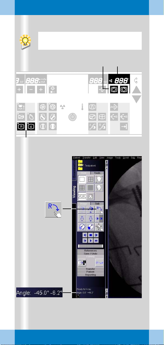
Image rotation and reversal
At the C-arm system
✧ Press one of the image rotation buttons
for the required direction of rotation (1).
➭ The angle of rotation in relation to the
starting position is shown (2).
✧ Press one of the image reversal buttons
to flip the image horizontally or
vertically
➭ The next time radiation is released, the
fluoroscopy image is in exactly this posi
tion.
At the monitor trolley
Image display and processing in the Viewing
task card is possible only for stored images
(e.g. single exposure).
(3).
-
✧ Activate the image rotation function (4).
✧ Rotate the image with the left mouse
(keep left mouse button pressed).
➭ Angle display in the control area (5):
First value = angle of rotation in relation to
starting position
Second value = angle of rotation in relation to last image setting
ARCADIS Varic Quick Guide
31
Page 32

Examination procedure
(1) (3) (2)
(4)
32
ARCADIS Varic Quick Guide
(5)
Page 33

Examination procedure
Collimator setting
For radiation protection reason collimators
should be inserted. These can be set at the
C-arm system.
(1) Moves the iris diaphragm into/out of the
beam path
(2) Rotates the semitransparent diaphragm
(3) Moves the semitransparent diaphragm
into/out of the beam path
The iris diaphragm is a multileaf collimator
used for concentric collimation of the radia
tion beam (4).
✧ Activate the iris diaphragm for small
objects, e.g. the wrists (1).
-
The semitransparent diaphragm acts as a
density compensation. A diaphragm is
moved close to the extremity on both sides.
Apart from reducing radiation, this prevents
overexposure at the edges of the
extremities
✧ Rotate the semitransparent diaphragm
corresponding to the position of the
object (2).
✧ Adapt the semitransparent diaphragm to
the size of the object (3).
(5).
ARCADIS Varic Quick Guide
33
Page 34

Examination procedure
(3)(1) (2)
34
ARCADIS Varic Quick Guide
Page 35

Examination procedure
Changing the contrast
If the image quality is insufficient, a different
gray-level curve can be selected at the control
panel of the C-arm system during the exami
nation to change the contrast of the image
(and all further images).
In addition, the edge enhancement of the live
images can be changed.
✧ If necessary, repeatedly press the follow-
ing buttons to change between preset values:
(1) Change contrast left monitor
(Examination task card)
(2) Change contrast right monitor
(References task card)
(3) Change edge enhancement right monitor
(References task card)
-
ARCADIS Varic Quick Guide
35
Page 36

Examination procedure
At the end of radiation, the image last
acquired is displayed (LIH, Last Image
Hold). If radiation is released again, the LIH
image is overwritten.
(1)
36
ARCADIS Varic Quick Guide
(2)
(3) (4)
Page 37

Examination procedure
Saving images
Single exposure
In this operating mode the generated images
are automatically saved in the local database
of the Patient Browser.
Fluoroscopy, pulsed fluoroscopy, subtraction, Roadmap
In these operating modes images are stored
in the temporary image memory and over
written by new images.
✧ To manually save the current image, press
one of the following buttons:
(1) Save image button on the hand switch
(2) Save image button on the C-arm system
➭ This image is displayed in the References
task card and stored in the local database.
-
Scrolling and printing
✧ Scroll through the stored images in the
References task card (3).
✧ Print out individual images from the
References task card with a local printer
(option) (4).
ARCADIS Varic Quick Guide
37
Page 38
Examination procedure
(3) (2) (4)
(1)
If Autoloop (option) is configured in the
exam set used, review of the scene is
started automatically at the end of radia
tion.
-
38
ARCADIS Varic Quick Guide
You can load the scene into the Viewing
task card at any time and review it there.
If the MPPS option is installed, the
Modality Performed Procedure Step
window for performance documentation is
now displayed automatically.
In the Configuration menu (Options >
Configuration > Transfer), define the rules
for auto transfer, e.g.:
❏ Required processing status
❏ Target addresses
❏ Data type
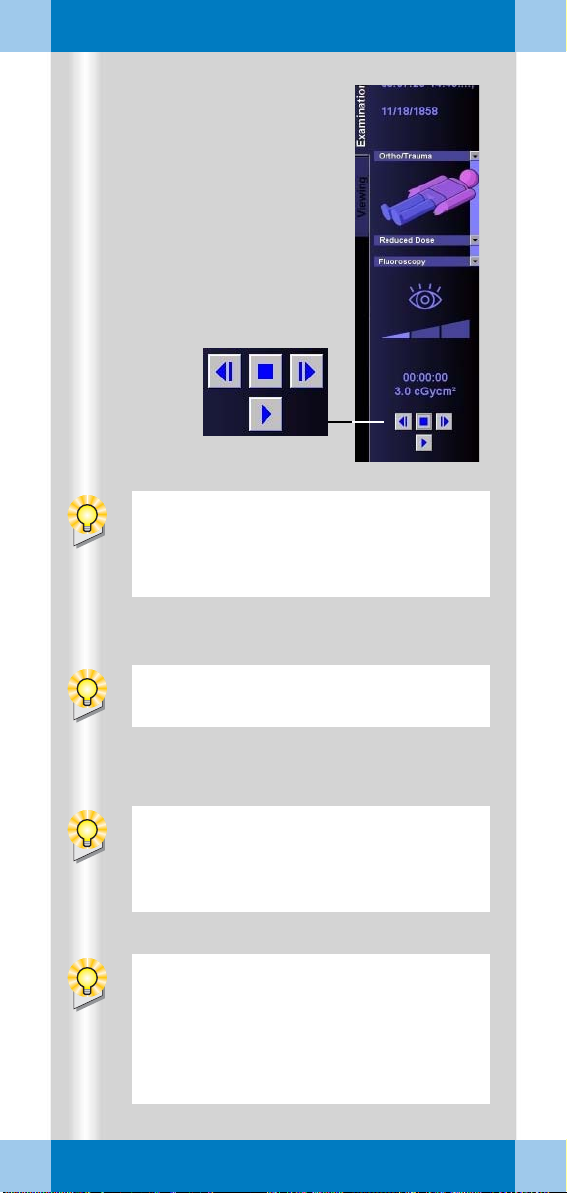
Page 39

Examination procedure
Fluoro Loop/LSH (option)
In the fluoroscopy, subtraction and Roadmap
modes, scenes can be reviewed and stored
(Last Scene Hold) during the examination.
Reviewing a scene
After radiation is ended, the buttons for controlling the scene review are displayed.
(1) Start
(2) Stop
(3) Previous frame
(4) Next frame
Storing the scene
As soon as the scene has been reviewed, it
can be stored.
✧ Select Patient > Save LSH Scene in the
main menu or press function key F9 on
the keyboard.
➭ The current scene (up to 120 images) is
stored in the local database.
Ending the examination
✧ Call up Patient > End Exam in the main
menu.
➭ Patient and examination data are deleted
from the Examination card.
➭ If Automatic transfer is activated, the
examination images are automatically
saved to CD-R or sent to the information
system (option).
ARCADIS Varic Quick Guide
39
Page 40

Subtraction and Roadmap
The Subtraction and Roadmap modes
are an option for C-arms used in cardiac and
vascular surgery.
(1)
(2)
40
(3)
ARCADIS Varic Quick Guide
Page 41

Subtraction and Roadmap
Performing a subtraction scene
Contrast medium injected into the vessels
helps to show vessels and changes of/in
these vessels (e.g. aneurysms, ruptures).
Procedure
✧ Prepare the examination in the
Examination task card:
(1) Selection of the required application pro-
gram
(2) Selection of the Subtraction mode
✧ Trigger the subtraction scene with the left
footswitch or the hand switch.
The footswitch or hand switch must remain
pressed during the entire series. If the series
is interrupted, it must be started again from
the beginning.
(3) The syringe symbol appears in the
Examination task card. The physician
now injects the contrast medium.
➭ After a few seconds the syringe symbol
disappears again. The physician can end
the contrast medium injection. The con
trast medium bolus remains displayed.
-
ARCADIS Varic Quick Guide
41
Page 42

Subtraction and Roadmap
If auto store is activated in the configuration menu, the images of a subtraction
scene are automatically saved in the local
database. They can then be retrieved for
postprocessing at the end of the examina
tion.
-
42
ARCADIS Varic Quick Guide
(1)
Page 43

Subtraction and Roadmap
Postprocessing a subtraction scene
✧ First, load the subtraction scene from the
Patient Browser into the Viewing task
card.
Pixelshift
Pixelshift allows you to make the mask and
fluoroscopy image coincide.
This function is used if the position of the
patient has changed in the course of the
series in relation to the position of the mask.
✧ Click the Pixelshift button (1).
➭ The mouse pointer appears as an arrow.
✧ Using the mouse, move the mask and flu-
oroscopy image so that one is on top of
the other.
➭ In the lower image area it is indicated by
how many pixels the mask was shifted in
the x-plane (= to the left or right) or the
y-plane (= up or down).
ARCADIS Varic Quick Guide
43
Page 44
Subtraction and Roadmap
(1)
44
ARCADIS Varic Quick Guide
(2)
Page 45

Subtraction and Roadmap
Auto Pixelshift
This function allows automatic pixelshift for a
selected region.
✧ Click the Auto Pixelshift button (1).
➭ The mouse pointer changes into a square.
✧ Move the square to the area in the image
where the misalignment can clearly be
seen.
✧ Press the left mouse button.
➭ The mask and fluoroscopy image are
made to coincide optimally in the marked
area.
➭ The shift of the mask in the x- and y-axis is
indicated in the bottom right image area.
Selecting a different mask
The selected application program defines
which of the generated images is used as the
mask in the subtraction series. This image is
then subtracted from all following images.
✧ Click Mask Next or Mask Previous (2).
➭ The mask for this series is changed in indi-
vidual steps. This change is automatically
adopted for the entire series.
ARCADIS Varic Quick Guide
45
Page 46

Subtraction and Roadmap
(1)
(2)
46
ARCADIS Varic Quick Guide
Page 47

Subtraction and Roadmap
Dual channel function
With this function the entire series is displayed unsubtracted during postprocessing in
the Native task card (on the right-hand moni
tor).
At the same time, the subtracted display is
shown in the Viewing task card (on the
left-hand monitor).
✧ Click the Dual channel function
button
(1).
➭ The entire series is additionally shown
unsubtracted on the right-hand monitor,
even when scrolling through individual
images of the series.
Native display in the Native task card
The image shown in the Native task card
directly corresponds to the image of the
series shown in the Viewing task card (2).
✧ Scroll through the individual images of the
series in the Viewing task card.
➭ The Native task card always shows the
corresponding image unsubtracted.
-
ARCADIS Varic Quick Guide
47
Page 48

Subtraction and Roadmap
(1)
48
ARCADIS Varic Quick Guide
(2)
(5)
(6)
(3)
(4)
(7)
Page 49

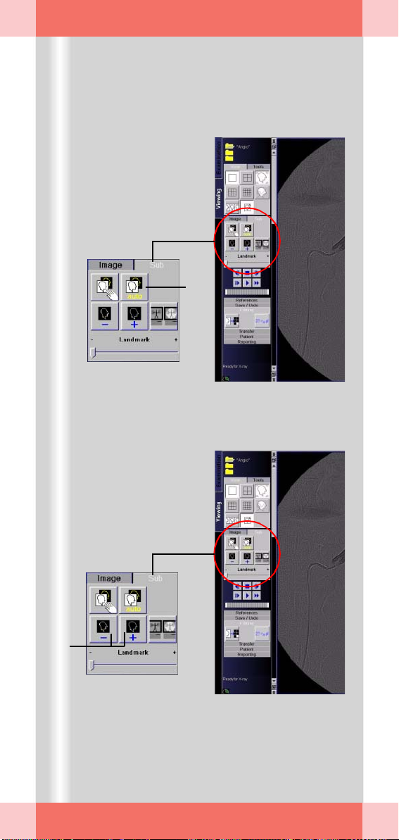
Subtraction and Roadmap
Landmark
The Landmark function allows you to subse-
quently add an anatomical background for orientation purposes (0 to 30 %).
✧ Keeping the left mouse button pressed,
drag the bar to the required value (1).
Movie mode
The replay of the subtraction scene can be
repeated in the Viewing task card.
✧ Select the required function with the
mouse:
(2) Scroll image back
(4) Stop the movie function
(5) Scroll image forward
(6) Replay series at half the speed
(7) Replay series in real time
(8) Replay series at double speed
ARCADIS Varic Quick Guide
49
Page 50

Subtraction and Roadmap
During catheter placement the images are
not automatically stored.
To manually save images, use the save button on the hand switch or C-arm system.
It is not necessary to create a subtraction
scene if the Roadmap exam connects to a
subtraction angiography. The existence of a
subtraction screen is then indicated by a
screen icon.
✧ In this case, press the ROADMAP but-
ton on the control panel once.
✧ Immediately start catheter positioning
under fluoroscopy control.
50
ARCADIS Varic Quick Guide
Page 51

Subtraction and Roadmap
Roadmap
The Roadmap mode is also used in vascular
surgery. This mode is used to place catheters
in vessels under fluoroscopy.
The examination comprises the following
steps:
Generation of a subtraction scene
✧ Select the Roadmap operating mode in
the Examination task card.
The procedure is the same as that described
in Section
❏ First, a mask is generated.
❏ Then, the vessel is filled with contrast
Catheter positioning in the vessel
❏ If radiation is released again, the catheter
Performing a subtraction scene.
medium and displayed using subtraction
technique.
placement is shown in real time in the
Examination task card.
ARCADIS Varic Quick Guide
51
Page 52

Postprocessing
2D images are postprocessed in the
Viewing task card.
(1)
(2)
52
(3)
)
4
(
ARCADIS Varic Quick Guide
Page 53

Postprocessing
Loading patient images into the Viewing task card
✧ Open the Viewing task card.
✧ Open the Patient B rows er with the
Call
up Patient Browser button on the
monitor trolley (1).
✧ Load the required series into the Viewing
task card with a double click (2).
✧ To load individual images, double-click on
the image symbol (3).
➭ The name of the patient is displayed in the
control area of the Viewing task card (4).
ARCADIS Varic Quick Guide
53
Page 54

Postprocessing
(1)
54
ARCADIS Varic Quick Guide
(2)
(3) (4)
Page 55

Postprocessing
Image display
In the View subtask card you can choose
between different monitor layouts.
(1) Different screen divisions
(2) Hiding graphics and patient data in the
image area
(3) Stripe display:
the images are arranged next to each
other
(4) Stack display:
the individual images are arranged one on
top of the other
ARCADIS Varic Quick Guide
55
Page 56

Postprocessing
(2)(1)
(3)
56
ARCADIS Varic Quick Guide
(4)
(5)
Page 57

Postprocessing
Measuring and annotations
In the Tools subtask card images can be mea-
sured and annotations can be added.
(1) Diaphragms
The subsequent simulation of diaphragms
improves the visualization of fine struc
tures that are difficult to see in the image
(2) Magnifying glass
Individual areas of the loaded image are
shown enlarged
(3) Annotations
Entering annotations for image areas via
the keyboard
(4) Calibrating and measuring distances
(5) Angle measurement
The angle between two straight lines to
be drawn is indicated
-
ARCADIS Varic Quick Guide
57
Page 58

Postprocessing
Distances cannot be measured directly in
the images, since the position of the object
in the beam path and thus the magnification
effect is not clear. A
performed first before a distance can be
clearly determined.
(1)
(2)
(3)
calibration must be
58
ARCADIS Varic Quick Guide
The calibration object must be
perpendicular to the central ray in the area
of the structure to be measured (generally
in the center of the measuring field to avoid
I.I. distortion).
(4)
(5)
Page 59

Postprocessing
Calibrating and measuring distances
❏ Calibrating (1st step)
✧ Activate the calibration function by click-
ing the corresponding button (1).
➭ A green line appears in the image area
which can be lengthened, shortened and
positioned as desired with the mouse (2).
✧ Draw the line along a known distance (2).
➭ As soon as you release the mouse button,
a dialog box appears (3).
✧ Enter the known distance and confirm
with OK (3).
➭ The calibration is shown in the image
area. At the same time, a measuring scale
appears on the right edge of the image.
❏ Measuring distances (2nd step)
✧ Activate the Distance function by clicking
the corresponding button (4).
✧ Using the left mouse button, draw a line
along the required structure.
➭ As soon as you release the left mouse
button, the distance from the start to the
end point of this line is shown (5).
ARCADIS Varic Quick Guide
59
Page 60

Postprocessing
(1)
(3)
(2)
(4)
60
ARCADIS Varic Quick Guide
(6)
(5)
Edge enhancement (3) means artificially
increasing the difference between two gray
levels.
Page 61

Postprocessing
Image manipulation
Images can be postprocessed in the Image
subtask card.
✧ Prior to postprocessing, activate the
required function by clicking the corre
sponding button:
(1) Change of contrast
The contrast is changed in four defined
steps
(2) Image rotation
Rotation with the left mouse button
pressed
(3) Edge enhancement
Edge enhancement is increased/reduced
in steps of ten
(4) Grayscale inversion
Change from positive to negative image
(5) Double/half image size
(6) Zoom/pan the image
Mouse at image edge: change image size
Mouse in image center: pan image
-
ARCADIS Varic Quick Guide
61
Page 62

Postprocessing
Windowing means changing the gray levels
in an image and thus the brightness (center
of the grayscale) and contrast (width of the
grayscale) of the image.
(1)
(2)
62
ARCADIS Varic Quick Guide
(3)
(4)
Page 63

Postprocessing
Windowing
❏ With buttons/softkeys
✧ Select the preset contrast levels by click-
ing the buttons (→ Page 61).
❏ With the keyboard of the monitor trolley:
✧ Select the brightness and contrast step
by step (1).
❏ With the mouse on the monitor trolley
✧ With the middle mouse button pressed,
move the mouse in the image (2).
Up/down movement changes the brightness
Movement to the left/right changes the
contrast
Display of window values
Edge enhancement and gray values of the
image are displayed in the lower image area:
(3) Edge enhancement
(4) Grayscale window
W = window width (contrast)
C = window center (brightness)
ARCADIS Varic Quick Guide
63
Page 64

Documentation
In radiology the terms "filming" (= printing
process), "camera" (= output device) and
"exposing" (= printing) are used for the
printing of patient images.
The syngo user interface uses corresponding terms.
(1) (2) (3)
64
(4)
(5)
ARCADIS Varic Quick Guide
Page 65

Documentation
Printing
If the printing function is configured, the
Filming task card additionally appears on the
right monitor.
Here, the images to be printed are collected
in film sheets, processed if necessary, and
then sent to the printer as a film job.
Procedure
(1) Copying images to the film sheet:
– from the C-arm system
– from the Viewing task card
– from the Patient Bro wser
(2) Editing/checking the film sheet:
in the Film Preview dialog or in the
Filming task card
(3) Printing the film job:
– on a local printer
– on a network printer
With a local printer you can print individual
images on paper or X-ray film directly in
the
OR.
Printing in the network is possible if a network printer (e.g. central printer in the OR or
the radiology department) is connected via
the network connection (4).
Copying images to the film sheet from the C-arm system (for local printing)
✧ Press the Print key on the control panel of
the C-arm system (5).
➭ The image shown on the right monitor is
copied to the film sheet.
➭ The local printer is preset as output device
for the print job.
ARCADIS Varic Quick Guide
65
Page 66

Documentation
(2)
(1)
66
ARCADIS Varic Quick Guide
(3)
(4)
Page 67

Documentation
Copying images to the film sheet from the Viewing task card
Print jobs can be created in the Viewing task
card in parallel with image postprocessing.
✧ Click the patient image to be copied to the
film sheet (1).
✧ Then click Copy to Film Sheet (2).
Copying images to the film sheet from the Patient Browser
If the complete data record of a patient is to
be printed on film, this can also be done
directly from the Patient Browser.
✧ Click the series to be printed in the local
database of the Patient Browser (3).
✧ Copy the patient images to the film
sheet
(4).
ARCADIS Varic Quick Guide
67
Page 68

Documentation
(1)
(2)
(3)
(4)
(5)
(6)
(7)
(8)
68
ARCADIS Varic Quick Guide
Page 69

Documentation
Checking the film job and printing from the film preview
✧ Click the Film Preview button in the
Patient Browser (1).
➭ A dialog box is opened which shows dif-
ferent functions for the film sheet:
(2) Dog ears for scrolling through the film
sheets
(3) Patient name
(4) Setting the number of copies of a film job
(5) Display of the status of individual film
jobs, e.g. "queued", "completed" etc.
(6) Deleting individual images from the film
sheet
(7) Sending the film job and exposing/print-
ing the film
(8) Automatic sending of a film job when film
sheet is full
✧ Click Expose to send the film job to the
printer/camera (7).
ARCADIS Varic Quick Guide
69
Page 70

Documentation
(1)
(2)
70
ARCADIS Varic Quick Guide
(3)
(4)
(5)
(6) (7)
Page 71

Documentation
Editing the film sheet in the Filming task card
✧ Click the Filming task card on the right
monitor (1).
❏ Layout
✧ Select the required film layout in the
Layout subtask card (2).
❏ Image display
✧ On the Images subtask card, select the
required display of the images on the film:
(3) Select text to be printed on film
All patient text (name, date of birth etc.),
customized text or no text
(4) Show or hide graphics (e.g. distance,
angle measurements)
(5) Enlargement of the image so that the
shorter sides fill the film segment. Parts
can be cut off from the longer sides.
(6) Adjust the image size to the film segment
(7) Return to the original image
ARCADIS Varic Quick Guide
71
Page 72

Documentation
(1)
(2)
(3)
72
ARCADIS Varic Quick Guide
(4)
(10)
(9)
(5)
(6)
(7)
(8)
Page 73

Documentation
❏ Camera/printer setting
✧ In the Camera subtask card, select a dif-
ferent camera/printer or film size, if necessary:
(1) Select the camera if several cameras are
configured
(2) Display of the film job status,
e.g.
"queued", "printed" etc.
(3) Select one of the film formats available in
the camera
❏ Zoom/Pan
✧ Activate the function by clicking the corre-
sponding button (4).
✧ Zoom/pan the image with the left mouse
button pressed.
Mouse at image edge: change image size
Mouse in image center: pan image
✧ If required, reset the image to the original
position and size (5).
Printing a film job from the Filming task card
✧ Set the number of copies (standard = 1
copy) (6).
✧ If necessary, delete individual images
from the film sheet (7).
✧ Send the film job to the camera manually (8)
or activate automatic exposure (9).
✧ If necessary, check the processing of the
film job (10).
➭ The status ("queued", "printed" etc.) of all
film jobs of the selected camera is
shown.
ARCADIS Varic Quick Guide
73
Page 74

Documentation
Only non-rewritable CDs, (CD-Rs), can be
used. Rewritable CDs (CD-RWs) are not
accepted.
The DICOM viewer is started directly from
the CD; no files are installed on the com
puter.
-
(1)
74
ARCADIS Varic Quick Guide
(2)
(1)
Page 75

Documentation
Burning CDs
As your system is configured for multi-session, you can store your data to unrecorded
CD-Rs, or CD-Rs that have already been writ
ten to. The new data is added to the old data
on the CD-R.
❏ DICOM Viewer
In the first session, a DICOM viewer is
written to the CD together with the image
data. This allows you to view the images
stored on the CD on any computer.
Exporting workflow
✧ Click the patient(s) in the Patient
Browser (1).
-
✧ In the menu bar of the Patient Browser,
click Tr a n s f e r > Ex p o r t to . . . (2).
➭ The dialog window for data export is
opened.
✧ Select the CD-R as the target and click
Export (1).
➭ The export process starts. The CD is auto-
matically labeled with the date and time.
ARCADIS Varic Quick Guide
75
Page 76

Reports
The prerequisite for both report types is the
registration and examination of a patient.
In
addition, for a LithoReport, the lithotripsy
function must be enabled on your system
and connected to the imaging system.
The radiation summary report is generated
automatically based on the present exami
nation data. It cannot be postprocessed.
-
76
(1)
(2)
(3)
ARCADIS Varic Quick Guide
Page 77

Reports
Generating reports
If the reporting function is enabled on your
system, important examination data are auto
matically compiled into a structured report for
documentation and treatment purposes.
Report types
❏ Radiation summary report
contains the accumulated values of the
examination for the number of exposures,
fluoroscopy time and dose area product
❏ LithoReport
contains the data on the diagnosis, treatment and postprocessing of an extracorporeal shockwave lithotripsy (ESWL) procedure
Using reports
You can read, print and send the reports and
complete the automatically entered data in
the LithoReport.
-
Managing reports
Reports are stored and managed in the
Patient Browser as additional data objects in
2 formats. They can be selected via the rele
vant icons like examination images:
(1) Report icon in the navigation area
(2) Report icon in the content area
Format: Structured Report (SR)
To open the Report Editor
(3) Report icon in the content area
Format: Secondary Capture (SC)
Loading e.g. into Viewing possible;
PACS-compatible
-
ARCADIS Varic Quick Guide
77
Page 78
Reports
(1)
(2)
A lithotripsy procedure is possible only
after a patient has been registered.
When you start an ESWL treatment, the
LithoReport editor is opened automatically
with the new report.
In the Viewing task card you can
open reports by clicking the relevant button on the Reporting
subtask card.
78
ARCADIS Varic Quick Guide
(3)
(4)
In the STATUS area you can see the current
processing and verification status. You can
change these statuses only in the case of
postprocessing reports (according to the
work progress made).
Page 79

Reports
Editing a LithoReport
Unlike in the case of the radiation summary
report, you can enter or subsequently change
part of the LithoReport data yourself.
Opening a report
✧ Select the required LithoReport in the
Patient Browser and select Reporting >
Open Report.
✧ Select the required report in the dialog
window displayed.
LithoReport editor
The selected report is displayed in the
LithoReport editor.
(1) Symbol buttons for printing a report
(2) Display of report status
Examination report (treatment in process)
Postprocessing report (treatment finished)
(3) Open card
(4) Button bar
ARCADIS Varic Quick Guide
79
Page 80

Reports
During an examination the LithoReport editor is automatically in edit mode.
(1)
(2)
To close the LithoReport editor, click OK.
With this button in the LithoReport
editor you can call up the print preview of the report.
80
ARCADIS Varic Quick Guide
(3)
(4)
Page 81

Reports
Completing and changing data
To modify data, you need to change into edit
mode. This is, however, not possible if the
report has already been completed (status
“completed”).
✧ Click Edit (1).
✧ Make your changes in the Patient/
Diagnosis, Therapy, Summary,
Postprocessing cards.
✧ To accept your changes, click Apply.
➭ The LithoReport editor remains open.
Printing and exporting a report
A r epor t ca n be expo rted onl y if it has reach ed
the status “completed” and “verified”.
Printing
✧ Click this button in the LithoReport
editor
(3).
➭ The Print Report dialog window is
opened (4).
✧ If necessary, change the print settings.
✧ Confirm with OK.
➭ The report is printed.
ARCADIS Varic Quick Guide
81
Page 82

Reports
Files in pdf format can be read and printed
on other computers with the Acrobat
Reader freeware program.
(1)
(2)
(3)
The program compiles all reports from the
local database that meet your specified cri
teria.
-
82
ARCADIS Varic Quick Guide
(4)
(5)
(6)
(7)
(8)
Page 83

Reports
Exporting a report as pdf file
The report is saved as a pdf file in the
CDR_OFFLINE directory. From there you can
write the file to CD.
✧ Select the required report in the Patient
Browser and call up Reporting > Export
Report to....
✧ Select a suitable layout for the pdf file in
the dialog window displayed (1).
✧ Enter a name for the pdf file in the Result
field (2).
✧ Confirm with OK (3).
Exporting for statistical evaluations
Data from LithoReports can be exported in
ASCII format. This text file is saved in the
CDR_OFFLINE directory.
A r epor t ca n be expo rted onl y if it has reach ed
the status “completed” and “verified”.
✧ Select the required report in the Patient
Browser and call up Reporting > Export
Statistics To....
✧ Enter your filter criteria in the three areas:
(4) Reports created between (period of time)
(5) Evaluation groups
(6) Evaluation parameters
✧ In the Result field, enter a name (ending
in “.txt”) for the export file (7).
✧ To start the export, click the Export
Statistics button (8).
ARCADIS Varic Quick Guide
83
Page 84

Connectivity
Monitor trolley
ARCADIS Varic Quick Guide
84
Monitor trolley
Page 85

Connectivity
ARCADIS can optionally be connected to a
network. The following two variants are avail
able:
DICOM System Basic Send/Receive + Storage Commitment, Print
(1) Send/Receive
Sending and receiving of patient images
(2) Storage Commitment
Requesting a confirmation that images
have been securely stored after sending
(3) Print
Printing of patient images on X-ray films
via a network
→ Page 65
DICOM System Advanced (in addition to the above-named functions)
(4) Worklist
Querying the worklist (all patients for a
system) and loading the patient data
(5) MPPS = Modality Performed Procedure
Step
Feedback to an information system about
the status of a work process
(6) Query/Retrieve
Searching for images in the network
(incl.
other modalities), importing of
images into the local database
-
ARCADIS Varic Quick Guide
85
Page 86

Connectivity
You can also receive images from another
system (CT, MR etc.) or workstation. For
this, the images have to be actively sent
from this system or workstation to
ARCADIS.
(1)
(2)
86
ARCADIS Varic Quick Guide
(3)
(4)
Page 87

Connectivity
Send/Storage Commitment
The Send to function allows you to archive
patient images in an information system or to
send them to another workstation for post
processing.
Send to
✧ Open the Patient B rows er (1).
✧ Select the patient (or individual examina-
tions) whose data you want to send.
✧ Click the Send to... button (2).
✧ Select the network node (recipient) and
confirm with Send (3).
➭ The images are sent to the selected
address (information system or worksta
tion).
-
-
Sending to a standard address
✧ Press the Send key on the keyboard of
the monitor trolley (4).
➭ The selected patient images are sent to
the first "standard" node configured by
Siemens Service.
ARCADIS Varic Quick Guide
87
Page 88

Connectivity
(1)
(2)
88
ARCADIS Varic Quick Guide
(3)
(4)
Page 89

Connectivity
Tracking network processes
✧ Click the Network Status button (1).
➭ Current processes in the network are
shown (2).
Storage Commitment
If patient data are sent or archived in an information system, the Storage Commitment
function requests a confirmation from the
receiving station that images have been
securely stored:
(3) Column for error messages
(4) Feedback in the status bar
("SV" = sent and verified)
➭ In the case of an error message, the data
in the Patient Browser must not yet be
deleted, because they have not yet been
properly saved or archived.
✧ Repeat the process again.
ARCADIS Varic Quick Guide
89
Page 90

Connectivity
Get Worklist offers the advantage of a sim-
plified workflow:
In an information system the OR plan
(i.e.
which patients are planned for a certain
operating room or C-arm) can be prepared
the day before and retrieved in the OR.
Patients can then be retrieved quickly just
before the procedure and the data can be
transferred to the Examination task card.
Patients no longer need to be registered
manually.
The Get Worklist function also prevents
the entry of incorrect patient data, since the
data do not need to be entered manually.
90
ARCADIS Varic Quick Guide
(1)
To update the worklist again, initiate a new
request to the information system by
double-clicking on the Scheduler.
(2)
(4)
(3)
Page 91

Connectivity
Get Worklist
The Get Worklist function contains a request
for a worklist within an information system.
✧ Double-click the Scheduler in the Patient
Browser (1).
➭ A worklist with patients whose data are
present in XA format (data format for con
ventional radiography) appears.
✧ Select the patient to be examined in the
Scheduler (2).
✧ Click the Patient Registration button (3).
➭ The Patient Registration window opens.
The data of the selected patient have
already been entered.
-
✧ Click Exam in the Patient Registration
window (4).
➭ The data are transferred to the
Examination task card, and the examina
tion can be started.
-
ARCADIS Varic Quick Guide
91
Page 92

Connectivity
(1)
(2)
92
ARCADIS Varic Quick Guide
(3)
(4)
Page 93

Connectivity
MPPS – Modality Performed
Procedure Step
MPPS (Modality Performed Procedure Step)
is a confirmation to an information system
that a certain process (in this case the exam
ination of a patient) has been completed.
Calling up MPPS after an examination
✧ Select Patient > End Examination in the
Examination task card (1).
➭ The MPPS dialog is displayed (2).
✧ If desired, enter information and com-
ments on the procedure (e.g. unusual
occurrences, complications).
✧ To end the dialog, click Completed (3).
➭ The OR documentation is sent to the
information system, where it is archived.
➭ The patient is deleted in the Scheduler.
-
Calling up MPPS manually
If you have accidentally closed the patient by
registering a new patient, you can open the
MPPS dialog manually.
✧ Select Patient > Show MPPS in the
menu bar of the Patient Browser (4).
ARCADIS Varic Quick Guide
93
Page 94

Connectivity
The Retrieve function is important above all
for preoperative images that are needed for
virtually any procedure.
(1)
94
ARCADIS Varic Quick Guide
(2)
(3)
(4)
Page 95

Connectivity
Query/Retrieve
❏ Query
A query to an information system can be
started. If the patient is already known to
the information system, the existing
images are displayed.
❏ Retrieve
Images can be imported into the local
database and loaded into the Viewing
task card.
✧ Click the Search button in the Patient
Browser (1).
➭ The search dialog opens (2).
✧ Enter the known patient data (unknown
data can be replaced by the * wildcard,
e.g. A*).
✧ Start the search by clicking Search (3).
➭ The patient images present in the infor-
mation system are displayed.
✧ Click the Import button (4).
➭ The patient images are imported into the
local database from where they can be
loaded into the Viewing task card.
ARCADIS Varic Quick Guide
95
Page 96

NaviLink 2D
Communication is implemented either
directly between the C-arm and the naviga
tion system or through a hospital network.
In the first case, the network cable from the
C-arm is connected directly to the naviga
tion system. In the second case it is
plugged into the network socket in the
OR
room.
-
-
96
(1)
Digital Radiography must be selected as
operating mode. The navigation system
does not accept images of other operating
modes.
ARCADIS Varic Quick Guide
Page 97

NaviLink 2D
Features
NaviLink 2D is a newly developed interface
that enables the communication of 2D image
data between ARCADIS Varic and a naviga
tion system.
With the exception of the connection of the
C-arm to the navigation system via the net
work cable and the generation of images for
navigation, the entire workflow takes place at
the navigation system.
Procedure
Preparation
✧ Set up the C-arm and the navigation sys-
tem and start both systems.
✧ Enter the patient data.
✧ Establish direct communication with the
aid of a network cable.
➭ The readiness of the C-arm is indicated by
an icon in the status bar of the
Examination task card (1).
-
-
✧ Select the examination parameters.
ARCADIS Varic Quick Guide
97
Page 98

NaviLink 2D
Confirmation is required only if the image is
to be used for navigation. All other images
are only stored in the Patient Browser at
the monitor trolley.
In general, 2 images are required.
98
ARCADIS Varic Quick Guide
All other work steps are performed at the
navigation system. The C-arm is still used
for postoperative follow-up exposures, for
example. In very small rooms, however, it is
often dismantled and taken out of the
room.
Page 99

NaviLink 2D
Procedure
✧ Release radiation.
➭ The image appears in the References
task card at the monitor trolley.
✧ Check the setting and image quality.
If
necessary, repeat the exposure.
✧ Confirm the selection of the image at the
navigation system by clicking Request
image.
➭ The image is automatically transferred
from the C-arm to the navigation system.
✧ Make further exposures until you have
reached the desired number of images for
navigation.
Final steps
✧ If necessary, dismantle the C-arm and
take it out of the room.
ARCADIS Varic Quick Guide
99
Page 100

Dismantling
(2)(1) (3)
S
T
O
P
ST
O
P
(4)
(5)
To define the switch-on duration yourself,
you can perform a full shut-down manually.
To do so, select Options > End session in
the main menu before turning the system
off.
100
(6)
ARCADIS Varic Quick Guide
 Loading...