

Page 1
Siemens
Energy & Automation
15900-745
Rev 3
November 2007
KIT INSTALLATION INSTRUCTION
SiPART PS2 and ValvePAC Series 760
Valve Positioner Mounting Kits for Rotary Actuators
This Instruction describes the use of a Siemens valve positioner mounting kit to mount a Siemens SiPART® PS2 or
ValvePAC™ Series 760 valve positioner on a typical rotary valve actuator.
positioner and for the actuator should be available for reference. If assistance is needed, refer to the
Customer/Product Support section of this instruction.
Figure 1 shows typical mechanical feedback configurations. The PS2 and Model 760 mount similarly and they use
similar feedback components.
KIT CONTENTS AND VARIATIONS
Each mounting kit contains:
• A main bracket for the particular positioner-to-actuator mounting requirements
1
Installation instructions for the valve
• Hardware to mount the bracket to the valve positioner
• Hardware to mount the bracket to the valve actuator – When bracket-to-actuator mounting hardware is not
supplied, actuator hardware that aligns with the main bracket mounting holes is removed from the actuator and
used to secure the main bracket.
• Additional hardware (e.g. spacers) as required – An installation may
require use of spacers, supplied in some kits, between the positioner
mounting bracket and the actuator.
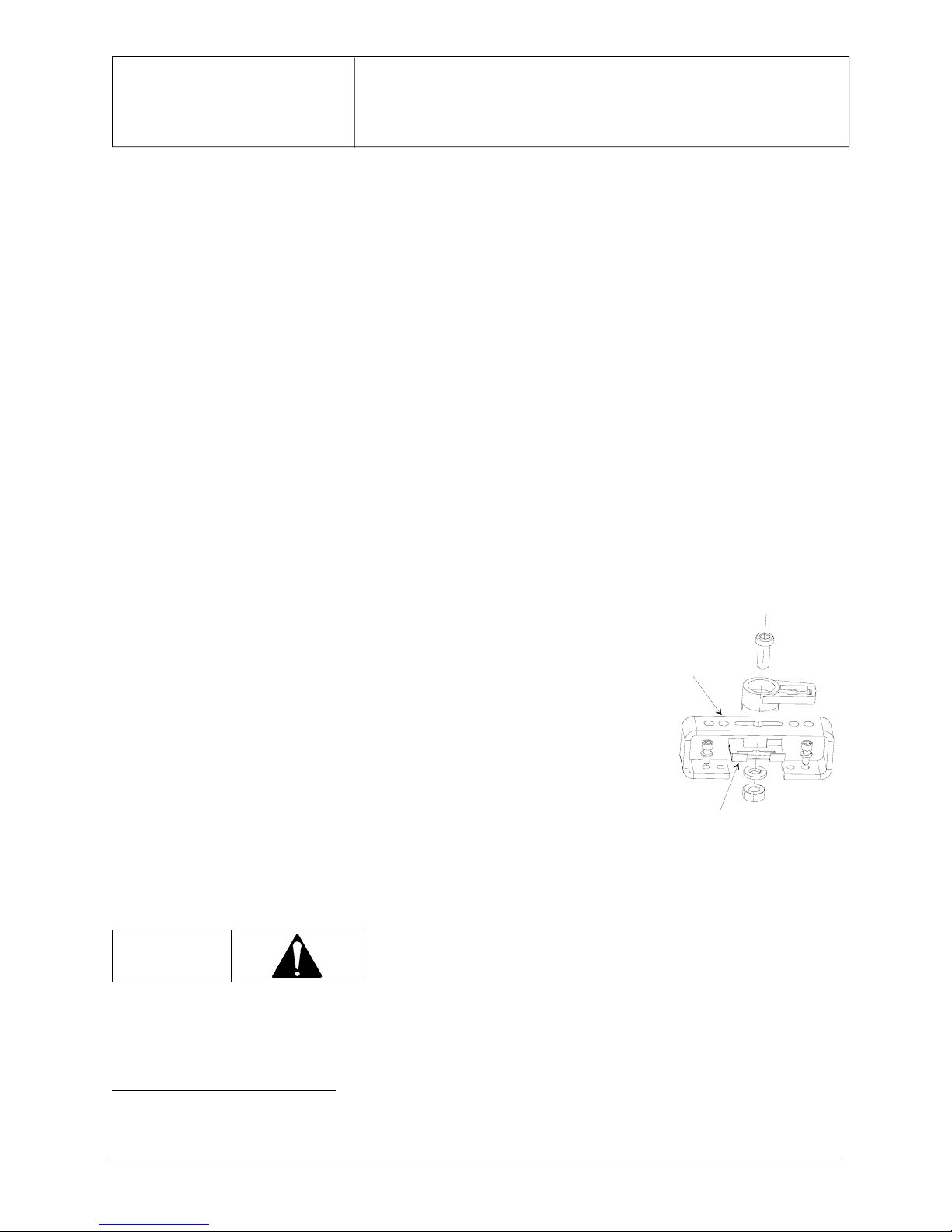
C-Style Sheet
Metal Coupling
• Feedback components to transfer the rotary motion of the actuator to the
valve positioner input shaft (may be sold separately)
• When using a sheet metal coupler (see the detail at right), ensure that
the PS2 feedback arm attaches securely to a C-style metal coupling by
positioning the included metal spacer between the coupling and the
lockwasher.
Spacer
KIT INSTALLATION
Before proceeding, read the actuator and valve positioner installation instructions and note all warnings and
cautions. Also, read the following cautions as they apply to all procedures in this instruction.
Do not apply supply pressure to the actuator or the valve positioner
CAUTION
during the installation process. Applying supply pressure before the
equipment is properly mounted could cause unexpected movement that
could lead to personal injury or equipment damage.
Perform the following steps to mount the positioner on the actuator and complete the feedback connection. Some
steps are performed only for certain models or certain actuator configurations as indicated.
1
This publication provides kit installation information and is intended to complement the product manuals. Refer to the product
manuals for applicable warnings and cautions and for detailed product procedures and specifications.
1
Page 2

15900-745
1. Fasten the mounting bracket to the valve positioner using the supplied M6 screws and lockwashers. Mounting
bracket shape will vary with the design of the actuator.
2. Note the positioner model and input shaft style and perform either step 2a or 2b.
2a) PS2 or 760 with D-shaped input shaft (Figure 1, detail 1 or 2) – Install the valve positioner coupler. Use
the included setscrew and fasten the coupler to the positioner input shaft. Apply a thread locking solution
to the setscrew. Tighten the setscrew on the flat of the shaft.
2b) 760 with factory installed NAMUR input shaft (Figure 1, detail 3) – No additional positioner coupler is
needed.
3. Mount the positioner/bracket assembly on the actuator and connect the mechanical feedback components as
follows.
3a) Place the assembly on the actuator. Note how the mounting bracket will be attached to the actuator – either
with hardware included in the kit or with hardware already in stalled in the actuator. Note how the supplied
feedback components will install – either directly or with a “secondary” coupling.
3b) If actuator-to-mounting bracket hardware is not supplied, identify the actuator hardware that aligns with
the mounting bracket mounting holes and remove that hardware from the actuator.
3c) Install any provided spacers between the mounting bracket and the actuator. Do not attach the bracket to
the actuator yet.
3d) If supplied, install a “secondary” coupler on the actuator. See Figure 1 for examples of secondary couplers.
These couplers will usually mount on the actuator’s valve position indicator or on the actuator shaft. The
“Secondary” coupler shape and manner of fastening will vary with the design of the actuator.
3e) Hold the positioner on the actuator and insert the positioner coupler into the slot in the actuator shaft, the
slot in the 6DR4004-8D feedback arm, or the slot in the secondary coupler.
Note
For a Wheel and Feedback Arm coupler, insert the feedback arm into the slot in the
secondary coupler. Insert the pin near the perimeter of the wheel into the hole in the
feedback arm.
4. Important: Check that all couplers are fully inserted. If the NAMUR coupler includes an antibacklash spring,
the spring must be fully inserted for the antibacklash action to function.
Note
Coupler engagement (in Figure 1, details 1 and 2) can be adjusted by loosening the
NAMUR coupler setscrew and repositioning the coupler on the positioner input shaft.
5. Use the mounting bracket hardware to attach the bracket to the actuator.
2
Page 3

15900-745
3
Page 4

15900-745
CUSTOMER/PRODUCT SUPPORT
Visit the Siemens Process Instrumentation product support page at
http://www2.sea.siemens.com/Products/ProcessInstrumentation/Support/Customer-Support.htm. Select the desired type of support (e.g. Local/Global, Product
Selection, Sales, Training, Technical (see below)).
Technical Support
Telephone 1 800 333 7421
E-mail techsupport.sea@siemens.com
Hours of Operation 8 a.m. to 4:45 p.m. eastern time, Monday through Friday (except holidays)
Technical Publications
in PDF
http://www2.sea.siemens.com/Products/Process-Instrumentation/Support/PI-User-
Manuals.htm then click the product line (e.g. Control Solutions)
Public Internet Site http://www2.sea.siemens.com/Products/Process-Instrumentation
Repair Service 1 215 646 7400 extension 3187
ValvePAC and SIPART are trademarks of Siemens Energy & Automation, Inc. Other trademarks are the property of their respective owners. All
product designations may be trademarks or product names of Siemens Energy & Automation, Inc. or other supplier companies whose use by
third parties for their own purposes could violate the rights of the owners.
Siemens Energy & Automation, Inc. assumes no liability for errors or omissions in this document or for the application and use of information in
this document. The information herein is subject to change without notice.
Procedures in this document have been reviewed for compliance with applicable approval agency requirements and are considered sound
practice. Neither Siemens Energy & Automation, Inc. nor these agencies are responsible for repairs made by the user.
4
 Loading...