

Page 1

GAMMA instabus
Technical Specification
November 2008
Colour touch panel UP 588/12 5WG1 588-2AB12
Colour touch panel UP 588/22 5WG1 588-2AB22
Accessories:
Design frame aluminium anodized 5WG1 588-8AB02
Design frame stainless steel 5WG1 588-8AB03
Design frame glass black 5WG1 588-8AB04
Design frame glass white 5WG1 588-8AB05
flush-type box 5WG1 588-8EB01
Siemens AG UP 588, 6 pages Technical Manual
Industry Sector, Building Technologies
Business Sector - Electrical Installation Technology © Siemens AG 2008 Update: http://www.siemens.com/gamma
PO Box 10 09 53, D-93009 Regensburg Subject to change without further notice
2.3.1.6/1
Product and Function Description
The Colour touch panel UP 588 is a multi-functional
display/control device for the KNX. The basis of the
device is a 320 × 240 pixels TFT colour display with touch
screen.
The colour depth is 263 K (R, G, B 6-bit), 218 colours. You
operate the panel directly via the touch screen.
The display has LED background illumination, which you
dim with the user interface.
• UP 588/12 Colour touch panel 5WG1 588-2AB12
230V AC
• UP 588/22 Colour touch panel 5WG1 588-2AB22
24V AC/DC
In conjunction with the corresponding application
program, the display can be used to display and control
up to 110 KNX functions of at least 20 control and
display pages. Time programmes with weekly schedules,
a presence simulation feature and scenes can be
programmed for these functions or logic functions set
up. Up to 16 active alarms can be indicated and
acknowledged on a alarm page or there is an option to
use these activating conditions for 16 event tasks.
The panel has an internal real time clock and can
therefore function as the master timer in a KNX system.
Via the system settings one of four different design
templates can be selected for the display and
operator interface.
The following accessories are needed for the colour
touch panel:
Design frame aluminium anodized 5WG1 588-8AB02
Design frame stainless steel 5WG1 588-8AB03
Design frame glass black 5WG1 588 8AB04
Design frame glass white 5WG1 588 8AB05
Relevant flush-type box 5WG1 588-8EB01
Application programs
25 CO Touch-Panel 910201
• Display and control of 110 KNX functions via at least
20 display and control pages. Each viewing and control
page includes up to 5 standard functions and 6
supplementary functions. A standard function can
contain up to 3 communication objects. An
supplementary function contains 1 communication
object.
• Implementation of time programmes with weekly
schedules for standard and supplementary function
objects
• Implementation of a presence simulation with
standard and supplementary function objects
• Implementation of scene programs with standard and
supplementary function objects
• Logic functions can be produced with supplementary
function objects
• Display of an alarm page with 16 alarm messages,
• Alternatively, the alarm activation conditions can be
used for 16 event tasks
• Date and time display, integrated real time clock
• Individual password protection for each page, for scene-,
weekly schedules-, logic programs and presence
simulation
• Selection out of four different design templates for the
display and operator interface
• Display of individual images on the start screen page or
up to 100 alternating images as a slide show
Installation notes
• The device can be used for permanent interior
installations in dry rooms.
• A masonry wall or cavity wall recess 161.5 × 135 × 64
mm is required to install the mounting socket.
• The depth of the recess must be at least 64 mm.
Page 2
GAMMA instabus
Technical Specification
November 2008
Colour touch panel UP 588/12 5WG1 588-2AB12
Colour touch panel UP 588/22 5WG1 588-2AB22
Accessories:
Design frame aluminium anodized 5WG1 588-8AB02
Design frame stainless steel 5WG1 588-8AB03
Design frame glass black 5WG1 588-8AB04
Design frame glass white 5WG1 588-8AB05
flush-type box 5WG1 588-8EB01
Technical Manual UP 588, 6 pages Siemens AG
Industry Sector, Building Technologies
Update: http://www.siemens.com/gamma © Siemens AG 2008 Business Sector - Electrical Installation Technology
Subject to change without further notice PO Box 10 09 53, D-93009 Regensburg
2.3.1.6/2
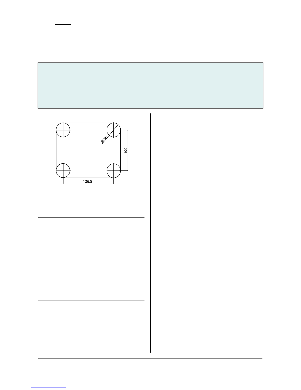
Figure 1: Drilling jig for cavity wall box Colour
touchpanel UP 588
V
DANGER
• The device may only be installed and commissioned by
an authorised electrician.
• The device may only be used in connection with the
named accessories, in particular the flush-type box.
• 230V devices which are not included with supply may
not be inserted in the flush-type box. It is also not
possible to loop through 230V cables.
• The prevailing safety and accident regulations should
be observed.
• The power supply voltage may only be connected to
the supply if the device has been fully installed.
• Protective isolation should be ensured between the
bus cable and the 230V power supply.
• For planning and construction of electric installations,
the relevant guidelines, regulations and standards of
the respective country are to be considered.
Technical specifications
Power supplies
• Bus voltage: via the bus line
• External power supply for:
• Colour Touch panel UP 588/12
230 V AC ±10%, 50/60 Hz
• Colour Touch panel UP 588/22
18 – 36 V DC, 400 mA, base isolated comp. 230 V
14 – 28 V AC, 400 mA, base isolated comp. 230 V
Operating elements
• Programming button to toggle between normal and
addressing modes
• Reset button to reset the device
• Resistive analogue touch with contact-sensitive area on
the display
Display elements
• Red programming LED for displaying normal/addressing
mode
• Graphics-capable TFT colour display 320 × 240 pixels
(1/4 VGA) with LED background lighting
Connections
• Bus line: KNX bus terminal, screwless
0.6... 0.8 mm ∅ solid, stripped length 5 mm.
• USB socket mini typ B (use only if needed for image
and symbols load)
• Power supply
stripped length: 6...7 mm
The following conductor/conductor cross-sections are
permitted:
- 0.5...2.5 mm
2
solid
- 0.5..0.1.5 mm
2
finely-stranded
Mechanical data
• Housing: Touch panel: plastic
• Frame: plastic
• Dimensions of visible surface at glass frame
(W × H × D): 244 × 176 × 4 mm
• Dimensions of visible surface at aluminium- and
stainless steel frame (W × H × D): 193 × 155 × 4 mm
• Mounting depth in flash-type box: 64 mm
• Installation: is screwed into the corresponding flush-
type box
• Dimensions of corresponding flush-type box (W × H ×
D): 161.5 × 135 × 64 mm, not included with supply
• Weight: approx. 510 g
Page 3
GAMMA instabus
Technical Specification
November 2008
Colour touch panel UP 588/12 5WG1 588-2AB12
Colour touch panel UP 588/22 5WG1 588-2AB22
Accessories:
Design frame aluminium anodized 5WG1 588-8AB02
Design frame stainless steel 5WG1 588-8AB03
Design frame glass black 5WG1 588-8AB04
Design frame glass white 5WG1 588-8AB05
flush-type box 5WG1 588-8EB01
Siemens AG UP 588, 6 pages Technical Manual
Industry Sector, Building Technologies
Business Sector - Electrical Installation Technology © Siemens AG 2008 Update: http://www.siemens.com/gamma
PO Box 10 09 53, D-93009 Regensburg Subject to change without further notice
2.3.1.6/3
1 2
3
4
5 6
Electrical safety
• Degree of pollution: 2
• Type of protection (according to EN 60529): IP20
• Protection class (to IEC 1140): I
• Overvoltage category: III
• Bus: safety extra-low voltage SELV 24V DC
• Device complies with EN50090-2-2
EMC requirements
Complies with EN 61000-6-3, EN 61000-6-2 and EN
50090-2-2
Ambient conditions
• Climatic withstand capability: EN 50090-2-2
• Ambient operating conditions: 0°C to +45°C
• Storage temperature: -25°C to +70°C
• Relative humidity (non-condensing): 5% to 93%
Markings
KNX/EIB
EC mark
In accordance with the EMC guideline (residential and
functional buildings) and the low voltage guideline
Location and function of the conjunction- and
operating elements
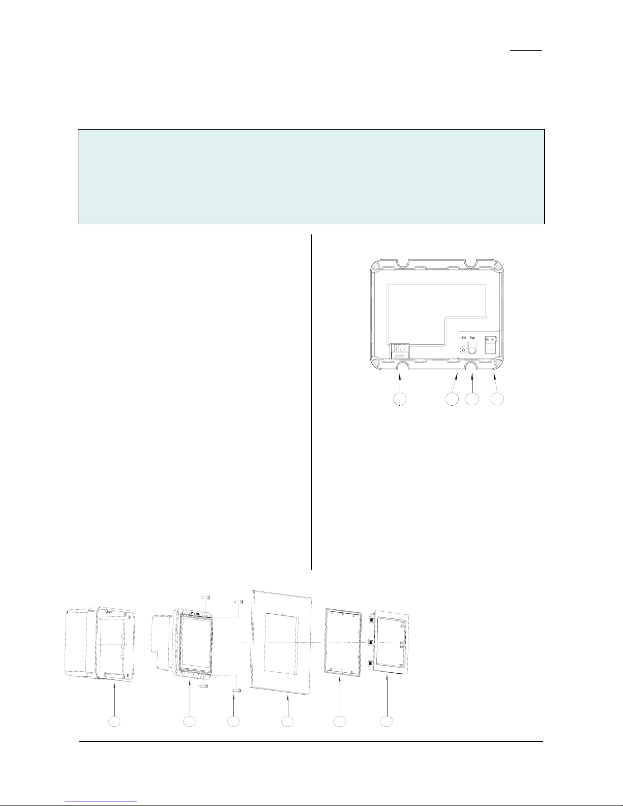
The device connections as well as the programming
button and programming LED which are required for the
commissioning stage are accessible at the back of the
device. Figure 2 shows the back of the device.
C DBA
Figure 2: Location of the connection and operating
elements
A Connection terminal 230 V or 24 V AC/DC
B Programming LED
C Programming button
D Bus terminal
Figure 3: Mounting the touch panel
1 Flush-type box
2 Colour touch panel
3 Fixing screws
4 different design frames
5 Ornamental frame
6 Passepartout frame
Page 4
GAMMA instabus
Technical Specification
November 2008
Colour touch panel UP 588/12 5WG1 588-2AB12
Colour touch panel UP 588/22 5WG1 588-2AB22
Accessories:
Design frame aluminium anodized 5WG1 588-8AB02
Design frame stainless steel 5WG1 588-8AB03
Design frame glass black 5WG1 588-8AB04
Design frame glass white 5WG1 588-8AB05
flush-type box 5WG1 588-8EB01
Technical Manual UP 588, 6 pages Siemens AG
Industry Sector, Building Technologies
Update: http://www.siemens.com/gamma © Siemens AG 2008 Business Sector - Electrical Installation Technology
Subject to change without further notice PO Box 10 09 53, D-93009 Regensburg
2.3.1.6/4
C3
C3.1
C3.3 C3.2
5 mm
C3
C3.4
C3
C3.4
"A"
C4.1
"B"
6....7mm
C4.2
C4
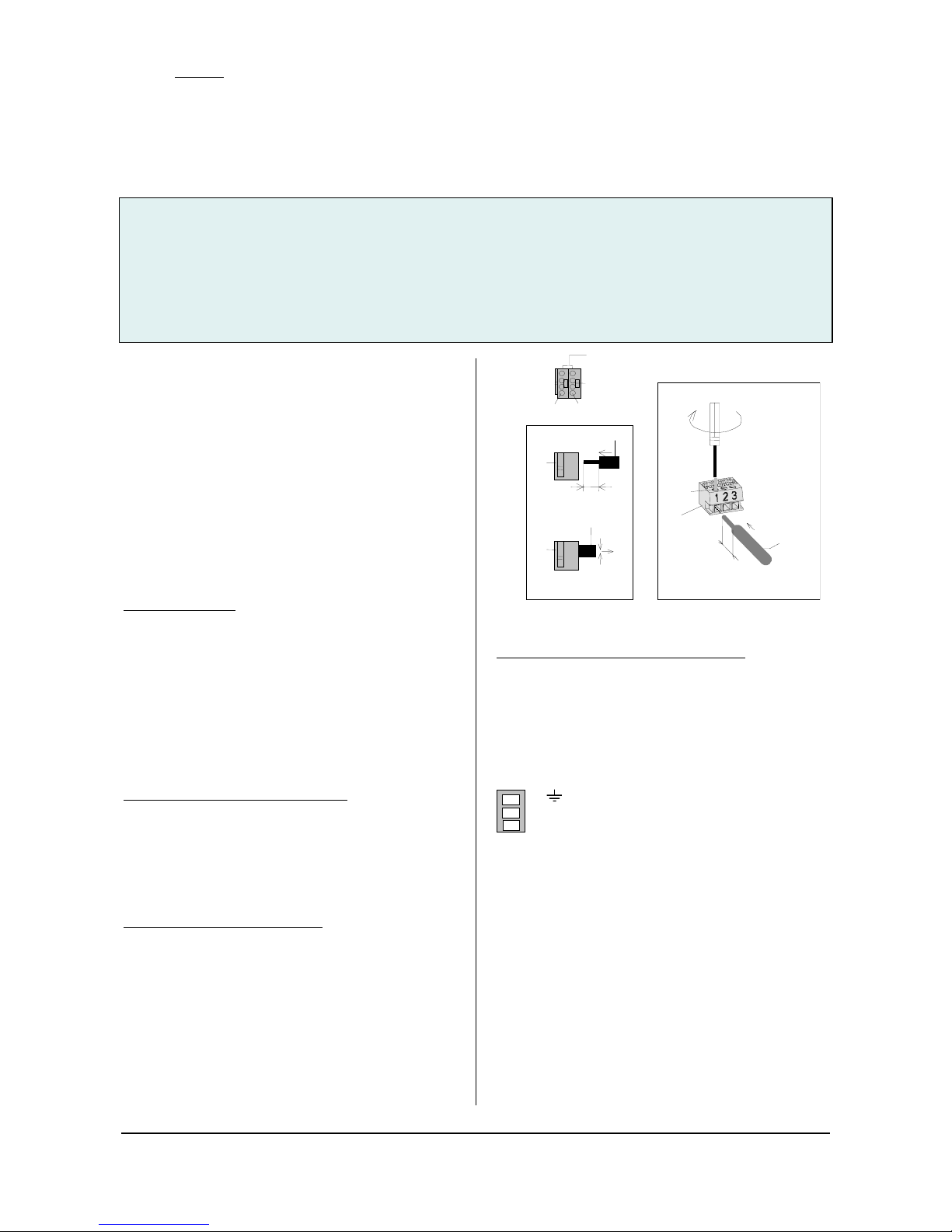
The bus cable is connected via a standard bus terminal D,
which is plugged into the corresponding terminal slot on
the right side of the housing. On the left, beside the
plug-in slot for the bus terminal are the programming
button C and the programming LED B. The connection
terminal for the 230 V power supply or, in the 24 V
version for 24 V supply are on the left side A of the
device. The terminal must be removed to connect the
power supply.
It is essential to obey the connection sequence marked
on the housing!
Mounting and wiring
General description
The device 2 may only be mounted in the flush-type box
1, to be ordered as an accessory. When the cable is
brought into the flush-type box, take care that the bus
cable is fed in through the bottom left hand recess and
the power supply cable is fed in through the right hand
recess. The bus and power supply cables must not be fed
into the flush-type box through the same recess. Inside
the box, the cable is to be routed so that there is a
guaranteed separation of at least 10 mm between bus
and power supply cables.
Connecting the bus cable (figure 4 "A")
− The bus terminal (C3) is suitable for solid conductors
with a diameter of 0.6 ... 0.8 mm.
− Strip off approx. 3 cm of the bus cable insulation
− Strip the insulation from the conductors (C3.4) to a
distance of approx. 5 mm and plug it into the
terminal (C3) (red = +, grey = -).
Clipping on bus terminal (figure 4)
− Plug the bus terminal into the guide slot and press it
(C3) downwards to the end stop
Figure 4: Connections
Connecting the power supply (Figure 4 "B")
− Strip the insulation from the conductor (C4.1) to a
distance of 6...7 mm, plug it into the power supply
connection terminals (C4) and tighten the screws
(C4.2).
Terminal assignment:
230V 24V
1
Earth In1: ± DC: AC
2 N Neutral conductor not connected
3 L Phase In2: ± DC: AC
After connecting the bus terminal and the power supply
to the conductors, the terminals are plugged into the
corresponding outlets on the touch panel. The power
supply must only be switched on when the plug is
engaged firmly in the device. After switching on the bus
voltage and the power supply, the programming button
can be pressed and the physical device address
programmed. The LED must go out after programming
the physical address.
The device is then screwed into the flush-type box with
the four screws 3 enclosed (see figure 3).
The protective film applied to the display surface can
now be removed. Do not use any sharp items or tools to
do this.
After the screwing and removal of the protective film,
the design frame 4 can be plugged into the device. At
Page 5
GAMMA instabus
Technical Specification
November 2008
Colour touch panel UP 588/12 5WG1 588-2AB12
Colour touch panel UP 588/22 5WG1 588-2AB22
Accessories:
Design frame aluminium anodized 5WG1 588-8AB02
Design frame stainless steel 5WG1 588-8AB03
Design frame glass black 5WG1 588-8AB04
Design frame glass white 5WG1 588-8AB05
flush-type box 5WG1 588-8EB01
Siemens AG UP 588, 6 pages Technical Manual
Industry Sector, Building Technologies
Business Sector - Electrical Installation Technology © Siemens AG 2008 Update: http://www.siemens.com/gamma
PO Box 10 09 53, D-93009 Regensburg Subject to change without further notice
2.3.1.6/5
the same time, take note of the direction for mounting
the frame. Finally, the passepartout blind 6 and the
ornamental frame 5 are plugged on to the display and
thus held by the frame. The mounting direction must
also be observed when mounting the passepartout blind.
It is to be plugged in such that all elements of the display
frame are covered completely.
V
Caution: Do not press directly on the display!
After mounting is completed, the device can be used (for
programming, see the application program description).
Please note the device can only be started after the
power supply and the bus voltage have been switched
on and this may take up to 1 minute.
Dismantling / exchanging the design frame
- First of all switch off the power supply
- The passepartout blind must be removed initially to
dismount the device or exchange the frame.
V
Caution: Do not press directly on the display!
After removing the passepartout blind, the ornamental
frame can be taken off and the design frame exchanged
or the device dismounted completely.
Disconnecting the power supply (figure 4 "B")
- To dismount the power supply terminal (C4), this must
be pulled downwards over the detente and out of the
slot. The removal can be made easier by lifting the
power supply connection terminal (C4) slightly with a
flat-bladed screwdriver. To do this, push the blade of
the screwdriver into the centre of the terminal detente
between the power supply connection terminal (C4)
and the base of the slot.
Removing the bus terminal (figure 4 "A")
- The bus terminal (C3) is in the left slot. It consists of
two parts (C3.2 and C3.3), each with four terminal
contacts. You must take care that both test sockets
(C3.1) are not damaged, either with the bus conductor
(accidental attempt to plug in) or with the screwdriver
(e.g. when trying to remove the bus terminal).
- Push the screwdriver carefully into the wire connection
slot of the grey part of the bus terminal (C3.3) and
then pull the bus terminal (C3) out of the device. When
pulling out the red part of the bus terminal, the grey
part remains plugged in.
Notice: Do not lever the bus terminal outwards from
below! Danger of short circuit!
Disconnecting the bus terminal (figure 4 "A")
Pull off the bus terminal (C3) and pull out its conductor
(C3.4) by turning it alternately backwards and forwards.
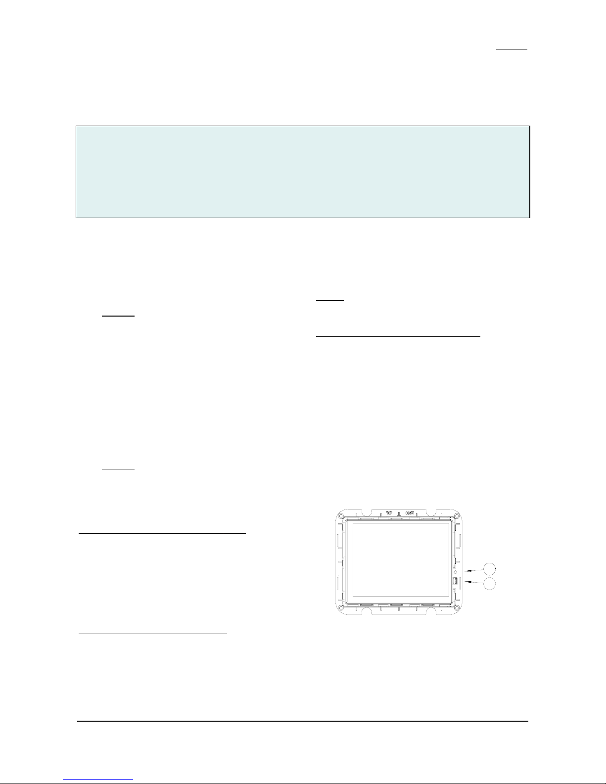
Resetting the device if there is an error
You reset the touch panel in the event of an error with
the reset button. The reset button F is accessible after
dismounting the design frame (see above). This is done
with the special tool. Should the display fail in rare cases
owing to a fault in the software or during the loading
process, tap the reset button. The device then restarts
within a few seconds and the design frame can be
remounted as described above. If the device will not
start, despite a reset, contact the manufacturer.
E
F
Extended programming via the front USB port
Pictures and symbols to order (see the user manual for
this) are transferred via the front mini-USB socket E. The
USB socket is accessible after dismounting the design
frame (see above). Connect the display to any PC with a
USB interface type A via a USB cable with a type B mini-
Page 6
GAMMA instabus
Technical Specification
November 2008
Colour touch panel UP 588/12 5WG1 588-2AB12
Colour touch panel UP 588/22 5WG1 588-2AB22
Accessories:
Design frame aluminium anodized 5WG1 588-8AB02
Design frame stainless steel 5WG1 588-8AB03
Design frame glass black 5WG1 588-8AB04
Design frame glass white 5WG1 588-8AB05
flush-type box 5WG1 588-8EB01
Technical Manual UP 588, 6 pages Siemens AG
Industry Sector, Building Technologies
Update: http://www.siemens.com/gamma © Siemens AG 2008 Business Sector - Electrical Installation Technology
Subject to change without further notice PO Box 10 09 53, D-93009 Regensburg
2.3.1.6/6
USB plug. The USB cable is part of the shipment and is
enclosed in the touch panel. It has a length of 1 m and
have a transfer rate of 480 MBit/sec. After completing
the transfer, remove the cable and mount the design
frame as described above.
Care instructions
The display's design frame and plastic surface can be
cleaned with off-the-shelf, solvent-free cleaning agents.
The display surface itself should be cleaned with a soft,
damp cloth (e.g. spectacles cloth) and, if necessary, a
mild glass cleaner.
Do not use any mechanical aids (rough sponge or similar
materials) for cleaning. The touch screen surface is easy
to scratch.
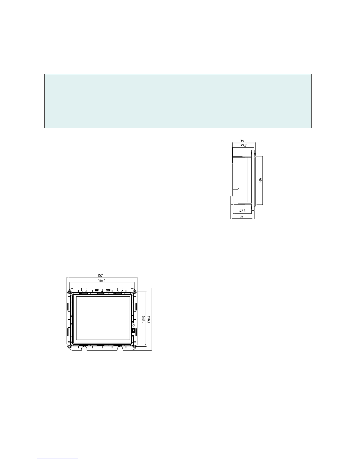
Dimension Diagram
The following sketch shows the exact dimensions of the
device.
Dimensions are given in mm.
General notes
• Any faulty device should be returned to the local
Siemens office.
• If you have further questions concerning the product,
please contact our Technical Support:
! +49 (0) 180 50 50-222
! +49 (0) 180 50 50-223
! www.siemens.com/automation/support-request
 Loading...