

Page 1
Siemens
Energy & Automation
USER'S MANUAL
UM353-1
Rev. 10
October 2001
Supersedes Rev. 9
s
2
42
453
.
TC2 0 5 3 . P
S P
PB1
PB2
M
LOOP
CLOSE
100
80
60
40
A
0
20
0
| ||
L
ACK
S
D
UNITS
100
|
OPEN
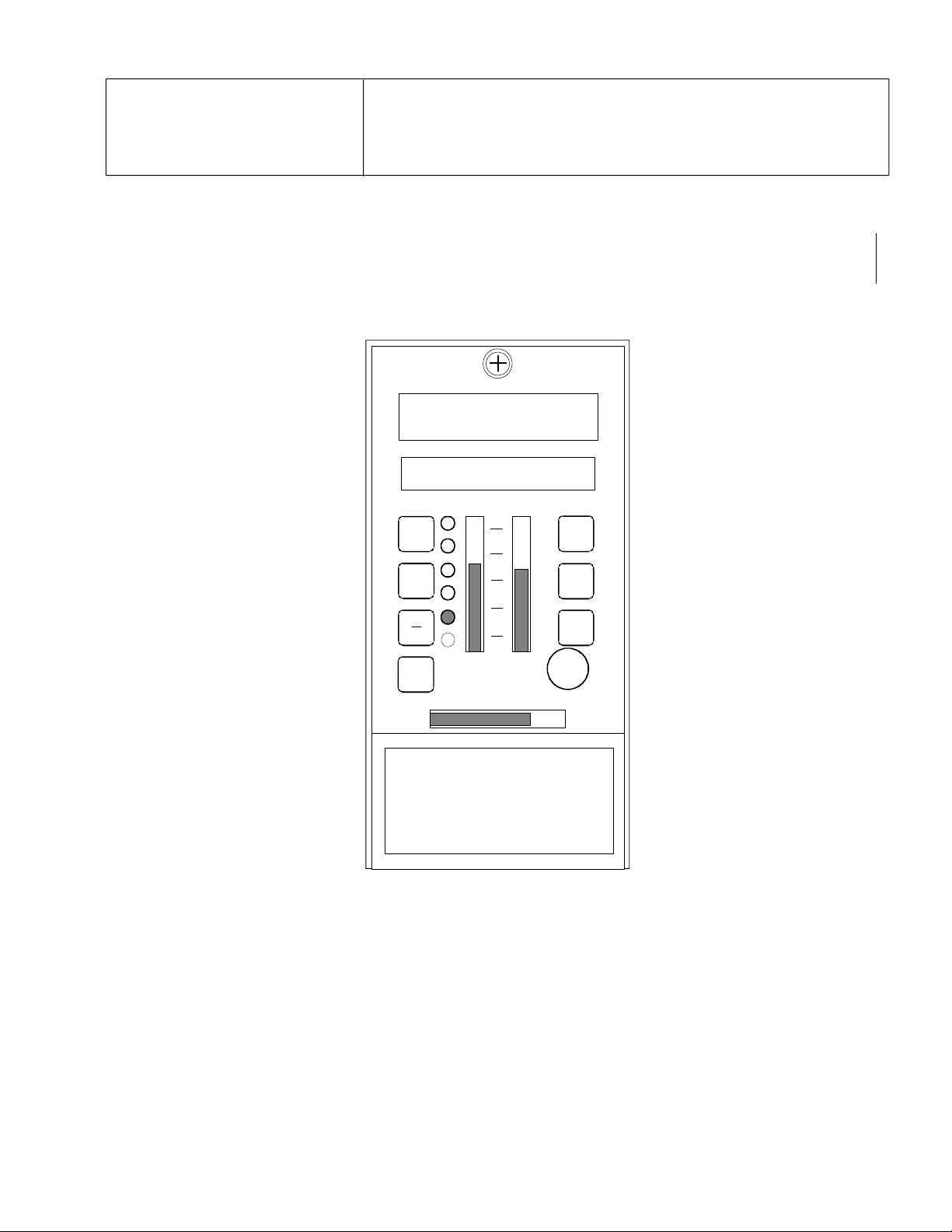
Moore 353
X03141S2
PROCESS AUTOMATION CONTROLLER
Page 2

Page 3

UM353-1 Contents
TABLE OF CONTENTS
SECTION AND TITLE PAGE
PREFACE........................................................................................................................................................... x
1.0 INTRODUCTION ....................................................................................................................................... 1-1
1.1 PRODUCT DESCRIPTION..................................................................................................................... 1-2
1.2 FUNCTION BLOCKS.............................................................................................................................1-4
1.2.1 LOOP Function Block Types.......................................................................................................... 1-4
1.2.2 Power Up Initialization ................................................................................................................... 1-6
1.2.3 Configuration ................................................................................................................................. 1-6
1.3 PRODUCT SUPPORT.............................................................................................................................1-6
1.4 EQUIPMENT DELIVERY AND HANDLING........................................................................................1-7
1.4.1 Factory Shipment ...........................................................................................................................1-7
1.4.2 Receipt of Shipment ....................................................................................................................... 1-7
1.4.3 Storage...........................................................................................................................................1-8
1.4.4 Typical Shipment Contents.............................................................................................................1-8
2.0 CONFIGURATION OVERVIEW..............................................................................................................2-1
2.1 STATION FUNCTION BLOCKS............................................................................................................ 2-1
2.2 STATION HARDWARE I/O BLOCKS...................................................................................................2-1
2.3 LOOP FUNCTION BLOCKS..................................................................................................................2-1
2.4 LIL GLOBAL DATA I/O FUNCTION BLOCKS .................................................................................... 2-2
2.5 ETHERNET DATA I/O FUNCTION BLOCKS....................................................................................... 2-3
2.6 LonWorks REMOTE I/O FUNCTION BLOCKS.....................................................................................2-3
2.7 CONFIGURATION PROCEDURE ......................................................................................................... 2-3
2.8 OPERATION DURING LOCAL ON-LINE CONFIGURATION.............................................................2-5
3.0 FUNCTION BLOCKS................................................................................................................................3-1
3.1 STATION FUNCTION BLOCKS............................................................................................................ 3-3
3.1.1 FCO LIB - Factory Configuration Library.......................................................................................3-3
3.1.2 SECUR - Security........................................................................................................................... 3-3
3.1.3 STATN - Station Parameters..........................................................................................................3-5
3.1.4 CLOCK - Real Time Clock (V2.0/2.2)............................................................................................ 3-7
3.1.5 ETHERNET - Ethernet Communication Network (V2.4)................................................................3-7
3.2 I/O AND LOOP FUNCTION BLOCKS ................................................................................................... 3-8
3.2.1 A/M - A/M Transfer....................................................................................................................... 3-8
3.2.2 ACS - ARCCOSINE..................................................................................................................... 3-10
3.2.3 ADD_ - Addition.......................................................................................................................... 3-10
3.2.4 AG3 - AGA 3 Orifice Metering of Natural Gas............................................................................3-11
3.2.5 AG7 - AGA 7 Measurement of Gas by Turbine Meters ................................................................ 3-13
3.2.6 AG8 - AGA 8 Compressibility Factors of Natural Gas................................................................ 3-14
3.2.7 AIE_ - Analog Input - Ethernet (V2.4)......................................................................................... 3-15
3.2.8 AIL_ - Analog Input - LIL............................................................................................................ 3-16
3.2.9 AIN_ - Analog Inputs................................................................................................................... 3-17
3.2.10 AINU_ - Analog Inputs, Universal .............................................................................................3-18
3.2.11 AIP_ - Analog Input lev_Percent............................................................................................... 3-20
3.2.12 ALARM - Alarm........................................................................................................................ 3-21
3.2.13 AND_ - AND Logic ................................................................................................................... 3-23
3.2.14 AOE_ - Analog Output- Ethernet (V2.4).................................................................................... 3-24
3.2.15 AOL_ - Analog Output - LIL...................................................................................................... 3-24
3.2.16 AOP_ - Analog Output lev_Percent............................................................................................ 3-25
October 2001 i
Page 4

Contents UM353-1
3.2.17 AOUT_ - Analog Outputs........................................................................................................... 3-26
3.2.18 ASN_ - ARCSINE ...................................................................................................................... 3-27
3.2.19 ATD_ - Analog Trend Display................................................................................................... 3-27
3.2.20 ATN_ - ARCTANGENT............................................................................................................ 3-28
3.2.21 BATOT - Batch Totalizer........................................................................................................... 3-29
3.2.22 BATSW - Batch Switch.............................................................................................................. 3-31
3.2.23 BIAS - Bias................................................................................................................................ 3-32
3.2.24 CIE_- Coil Inputs - Ethernet (V2.4)............................................................................................ 3-33
3.2.25 CHR_ - Characterizer................................................................................................................. 3-33
3.2.26 CMP_ - Comparator ................................................................................................................... 3-34
3.2.27 COS_ - COSINE ........................................................................................................................ 3-34
3.2.28 DAM_ - Deviation Amplifier...................................................................................................... 3-35
3.2.29 DID_ - Digital Input lev_Discrete............................................................................................... 3-36
3.2.30 DIE_ - Digital Input - Ethernet (V2.4)........................................................................................ 3-37
3.2.31 DIL_ - Discrete Input _ LIL........................................................................................................ 3-37
3.2.32 DIN_ - Digital Inputs ................................................................................................................. 3-38
3.2.33 DINU_- Digital Inputs, Universal............................................................................................... 3-39
3.2.34 DIS_ - Digital Input _ State ........................................................................................................ 3-40
3.2.35 DIV_ - Division .......................................................................................................................... 3-41
3.2.36 DNC_ - Divide by N Counter...................................................................................................... 3-41
3.2.37 DOD_ - Digital Output lev_Discrete........................................................................................... 3-42
3.2.38 DOE_ - Digital Output - Ethernet (V2.4).................................................................................... 3-43
3.2.39 DOL_ - Discrete Output - LIL .................................................................................................... 3-43
3.2.40 DOS__ - Digital Output State..................................................................................................... 3-44
3.2.41 DOUT_ - Digital Outputs........................................................................................................... 3-45
3.2.42 DTM_ - Dead Time Table.......................................................................................................... 3-46
3.2.43 DYT_ - Delay Timer .................................................................................................................. 3-47
3.2.44 E/I - External/Internal Transfer Switch....................................................................................... 3-48
3.2.45 ESL - Events Sequence Logger................................................................................................... 3-49
3.2.46 EXP_ - NATURAL EXPONENTIATION.................................................................................. 3-50
3.2.47 EXT_ - EXPONENTIATION ..................................................................................................... 3-50
3.2.48 FTG_ - Falling Edge Trigger...................................................................................................... 3-51
3.2.49 GB_ - Gain & Bias..................................................................................................................... 3-51
3.2.50 HLD_ - Hold ..............................................................................................................................3-51
3.2.51 ID - ID Controller ....................................................................................................................... 3-52
3.2.52 LL_ - Lead/Lag ..........................................................................................................................3-53
3.2.53 LMT_ - Limit............................................................................................................................. 3-53
3.2.54 LN_ - NATURAL LOGARITHM............................................................................................... 3-54
3.2.55 LOG_ - LOGARITHM BASE 10................................................................................................ 3-54
3.2.56 MTH_ - Math............................................................................................................................. 3-55
3.2.57 MUL_ - Multiplication ...............................................................................................................3-56
3.2.58 NND_ - NAND Logic................................................................................................................. 3-56
3.2.59 NOR_ - NOR Logic .................................................................................................................... 3-57
3.2.60 NOT_ - NOT Logic.................................................................................................................... 3-57
3.2.61 ODA - Operator Display for Analog indication & alarming (V2.2)............................................ 3-58
3.2.62 ODC - Operator Display for Controllers .....................................................................................3-60
3.2.63 ODD - Operator Display for Discrete indication & control (V2.2)............................................... 3-62
3.2.64 ODP - Operator Display for PushButtons (V2.2) ......................................................................... 3-64
3.2.65 ODS - Operator Display for Sequencer ....................................................................................... 3-66
3.2.66 ON/OFF - On/Off Controller ...................................................................................................... 3-68
3.2.67 OR_ - OR Logic ......................................................................................................................... 3-69
ii October 2001
Page 5

UM353-1 Contents
3.2.68 ORSL - Override Selector........................................................................................................... 3-69
3.2.69 OST_ - One Shot Timer ............................................................................................................. 3-70
3.2.70 PB1SW - PB1 Switch ................................................................................................................. 3-71
3.2.71 PB2SW - PB2 Switch ................................................................................................................. 3-72
3.2.72 PB3SW - PB3 Switch ................................................................................................................. 3-73
3.2.73 PCOM - Phase COMmunication................................................................................................. 3-74
3.2.74 PD - PD Controller..................................................................................................................... 3-76
3.2.75 PID - PID Controller .................................................................................................................. 3-78
3.2.76 PIDAG - PIDAG Controller .......................................................................................................3-80
3.2.77 PRSEQ - Program Sequencer ...................................................................................................... 3-82
3.2.78 QHD_ - Quickset Hold ............................................................................................................... 3-84
3.2.79 RATIO - Ratio............................................................................................................................ 3-85
3.2.80 RCT_ - Repeat Cycle Timer........................................................................................................ 3-86
3.2.81 RLM_ - Rate Limiter.................................................................................................................. 3-87
3.2.82 ROT_ - Retentive On Timer ....................................................................................................... 3-87
3.2.83 ROUT_ - Relay Outputs..............................................................................................................3-88
3.2.84 RSF_ - RS Flip-Flop................................................................................................................... 3-88
3.2.85 RTG_ - Rising Edge Trigger ...................................................................................................... 3-89
3.2.86 RTT_ - Real Time clock Trip (V2.0) ..........................................................................................3-89
3.2.87 SCL_ - Scaler............................................................................................................................. 3-90
3.2.88 SEL_ - Signal Selector ............................................................................................................... 3-90
3.2.89 SETPT - Setpoint ....................................................................................................................... 3-91
3.2.90 SIN_ - SINE............................................................................................................................... 3-92
3.2.91 SPLIM - Setpoint Limit.............................................................................................................. 3-93
3.2.92 SRF_ - SR Flip-Flop................................................................................................................... 3-94
3.2.93 SRT_ - Square Root .................................................................................................................... 3-94
3.2.94 SUB_ - Subtraction ..................................................................................................................... 3-95
3.2.95 TAN_ - TANGENT.................................................................................................................... 3-95
3.2.96 TH_ - Track & Hold................................................................................................................... 3-96
3.2.97 TOT_ - Totalizer (V2.3)............................................................................................................. 3-96
3.2.98 TSW_ - Transfer Switch............................................................................................................. 3-97
3.2.99 XOR_ - Exclusive OR Logic....................................................................................................... 3-97
4.0 FACTORY CONFIGURED OPTIONS .....................................................................................................4-1
4.1 FCO101 - Single Loop Controller w/ Tracking Setpoint...........................................................................4-2
4.2 FCO102 - Single Loop Controller w/ Fixed Setpoint ................................................................................ 4-3
4.3 FCO103 - External Set Controller with Tracking Local Setpoint..............................................................4-4
4.4 FCO104 - External Set Controller with Non-Tracking Local Setpoint ...................................................... 4-6
4.5 FCO105 - Ratio Set Control w/ Operator Setpoint Limits.........................................................................4-8
4.6 FCO106 - Single Loop Controller w/ Operator Setpoint Limits .............................................................. 4-10
4.7 FCO107 - Dual Loop Controller ............................................................................................................ 4-11
4.8 FCO121 - Cascade Control.................................................................................................................... 4-13
4.9 FCO122 - Cascade Control w/ Operator Setpoint Limits........................................................................ 4-15
5.0 LONWORKS COMMUNICATIONS........................................................................................................5-1
6.0 NETWORK COMMUNICATIONS........................................................................................................... 6-1
6.1 MODBUS DATA MAPPING .................................................................................................................. 6-1
6.2 * Refer to the AIE function block in the Function Blocks section for details.LIL DATA MAPPING ........6-2
6.2 LIL DATA MAPPING ............................................................................................................................6-3
6.2.1 Station Data....................................................................................................................................6-3
6.2.2 Control Loop Data .......................................................................................................................... 6-5
October 2001 iii
Page 6

Contents UM353-1
6.2.3 Sequence Loop Data.......................................................................................................................6-6
6.2.4 Analog Indicator Loop Data ...........................................................................................................6-9
6.2.5 Discrete Indicator Loop Data........................................................................................................ 6-10
6.2.6 Pushbutton Loop Data ..................................................................................................................6-11
7.0 DATA MAPPING ....................................................................................................................................... 7-1
7.1 CONNECTING TO APACS 39ACM, MYCROADVANTAGE, ProcessSuite, i|ware PC.........................7-1
7.1.1 APACS...........................................................................................................................................7-1
7.1.2 MYCROADVANTAGE.................................................................................................................7-1
7.1.3 ProcessSuite ................................................................................................................................... 7-2
7.1.4 i|ware PC ........................................................................................................................................ 7-2
7.2 STATION DATA.................................................................................................................................... 7-3
7.2.1 Integer Data (16-bit Integer)...........................................................................................................7-3
7.2.2 Station String Data (8-bit ASCII Char - 2/Word)............................................................................ 7-5
7.2.3 Station Coil Data (1-bit)................................................................................................................. 7-5
7.2.4 Station Status Word (SSW).............................................................................................................7-5
7.3 LOOP DATA ..........................................................................................................................................7-6
7.3.1 Dynamic Loop Integer Data ............................................................................................................ 7-7
7.3.2 Variable Loop Integer Data.............................................................................................................7-8
7.3.3 Static Loop Integer Data............................................................................................................... 7-10
7.3.4 Dynamic Loop Floating Point Data (32-bit IEEE)......................................................................... 7-11
7.3.5 Variable Loop Floating Point Data (32-bit IEEE)..........................................................................7-12
7.3.6 Static Loop Floating Point Data (32-bit IEEE).............................................................................. 7-14
7.3.7 String Loop Data (8-bit ASCII Char - 2/Word)............................................................................. 7-16
7.3.8 Coil Loop Data (1-bit) .................................................................................................................. 7-19
7.3.9 PCOM Block Status...................................................................................................................... 7-31
7.3.10 Sequencer Loop I/O Coil Data (1-bit) .........................................................................................7-33
7.3.11 LonWorks Remote I/O (Models 352P, 353, 354N)...................................................................... 7-35
7.3.12 Trend Data (Loop Defined by MLTP)......................................................................................... 7-43
7.3.13 Configuration Data Sequencer Loop ........................................................................................... 7-46
7.3.14 LIL Alarm Type Word (ATW) ................................................................................................... 7-48
8.0 INSTALLATION........................................................................................................................................8-1
8.1 INSTALLATION CONSIDERATIONS ..................................................................................................8-1
8.2 ENVIRONMENTAL CONSIDERATIONS............................................................................................. 8-1
8.3 MECHANICAL INSTALLATION..........................................................................................................8-3
8.3.1 Removable Connectors and Covers................................................................................................. 8-3
8.3.2 Panel and Rack Mounting Guidelines............................................................................................. 8-5
8.3.3 Station Mounting............................................................................................................................8-7
8.4 ELECTRICAL INSTALLATION............................................................................................................8-8
8.4.1 Wiring Guidelines.......................................................................................................................... 8-8
8.4.2 Analog Signal Input Wiring (4-20 mA, 1-5 Vdc, and mV)........................................................... 8-13
8.4.3 Analog Output Wiring (4-20 mA, 1-5 Vdc) ..................................................................................8-15
8.4.4 Digital Input and Output Wiring...................................................................................................8-16
8.4.5 Thermocouple Input Wiring......................................................................................................... 8-18
8.4.6 RTD Input Wiring ........................................................................................................................ 8-19
8.4.7 Ohms and Slidewire Input Wiring................................................................................................ 8-20
8.4.8 Relay Output Wiring .................................................................................................................... 8-20
8.4.9 Local Instrument Link Wiring...................................................................................................... 8-20
8.4.10 LonWorks Wiring ......................................................................................................................8-22
8.4.11 Modbus Wiring .......................................................................................................................... 8-22
8.4.12 Ethernet Wiring .........................................................................................................................8-22
iv October 2001
Page 7

UM353-1 Contents
8.4.13 Wiring to a Model 363 VIEWPAC Recorder .............................................................................. 8-24
8.4.14 Power Wiring............................................................................................................................. 8-24
8.5 FACTORY CALIBRATION.................................................................................................................. 8-26
9.0 LOCAL FACEPLATE OPERATION........................................................................................................ 9-1
9.1 NORMAL OPERATION MODE............................................................................................................. 9-1
9.2 CONFIGURATION MODE..................................................................................................................... 9-3
9.3 AUTOTUNE PROCEDURE.................................................................................................................... 9-4
9.4 REMOVABLE CONFIGURATION BOARD ..........................................................................................9-7
9.5 REAL TIME CLOCK/CONFIGURATION BACKUP BOARD ............................................................... 9-7
10.0 CONTROLLER AND SYSTEM TEST.................................................................................................. 10-1
10.1 CONTROLLER CONFIGURATION AND TEST................................................................................ 10-1
10.1.1 Connections and Power .............................................................................................................. 10-1
10.1.2 Configuration............................................................................................................................. 10-2
10.1.3 Input/Output............................................................................................................................... 10-2
10.1.4 Auto/Manual.............................................................................................................................. 10-2
10.1.5 Modifying an FCO .....................................................................................................................10-2
10.1.6 Alarms....................................................................................................................................... 10-4
10.1.7 TAG........................................................................................................................................... 10-5
10.1.8 QUICK....................................................................................................................................... 10-5
10.1.9 TUNE......................................................................................................................................... 10-6
10.1.10 View mode............................................................................................................................... 10-7
10.2 SYSTEM CHECKOUT ....................................................................................................................... 10-7
11.0 MAINTENANCE.................................................................................................................................... 11-1
11.1 TOOLS AND TEST EQUIPMENT ..................................................................................................... 11-1
11.2 PREVENTIVE MAINTENANCE........................................................................................................ 11-2
11.2.1 Environmental Considerations....................................................................................................11-2
11.2.2 Visual Inspection ........................................................................................................................ 11-2
11.2.3 Cleaning.....................................................................................................................................11-2
11.2.4 Circuit Board Handling.............................................................................................................. 11-3
11.3 TROUBLESHOOTING .......................................................................................................................11-3
11.4 ERROR CODES.................................................................................................................................. 11-7
11.5 ASSEMBLY REPLACEMENT ......................................................................................................... 11-12
11.5.1 Fuse.......................................................................................................................................... 11-12
11.5.2 Display Assembly..................................................................................................................... 11-12
11.5.2.1 To Replace a Display Assembly....................................................................................... 11-12
11.5.2.2 To Replace the Bezel or Circuit Board............................................................................. 11-13
11.5.3 MPU Controller Board ............................................................................................................. 11-14
11.5.4 I/O Expander Board ................................................................................................................. 11-15
11.5.5 Accessory Boards ..................................................................................................................... 11-16
11.5.6 Ethernet Cable.......................................................................................................................... 11-20
12.0 CALIBRATION...................................................................................................................................... 12-1
12.1 ANALOG INPUT (AIN1-4)................................................................................................................. 12-2
12.2 ANALOG OUTPUT (AOUT1-3)......................................................................................................... 12-3
13.0 CIRCUIT DESCRIPTION...................................................................................................................... 13-1
13.1 OVERVIEW........................................................................................................................................ 13-1
13.2 MPU CONTROLLER BOARD............................................................................................................ 13-2
13.3 I/O EXPANDER BOARD.................................................................................................................... 13-2
13.4 LonWorks BOARD.............................................................................................................................. 13-3
13.5 LOCAL INSTRUMENT LINK (LIL) NETWORK BOARD................................................................. 13-3
October 2001 v
Page 8

Contents UM353-1
13.6 ETHERNET BOARD .......................................................................................................................... 13-3
14.0 MODEL DESIGNATION AND SPECIFICATIONS............................................................................. 14-1
14.1 MODEL DESIGNATION.................................................................................................................... 14-1
14.2 ACCESSORIES................................................................................................................................... 14-3
14.3 SERVICE PARTS KITS ...................................................................................................................... 14-4
14.4 MECHANICAL SPECIFICATIONS.................................................................................................... 14-6
14.5 POWER INPUT REQUIREMENTS ....................................................................................................14-6
14.6 MPU CONTROLLER BOARD SPECIFICATIONS............................................................................. 14-7
14.7 I/O EXPANDER BOARD SPECIFICATIONS ....................................................................................14-7
14.8 COMMUNICATION BOARDS......................................................................................................... 14-10
14.8.1 LonWorks Board...................................................................................................................... 14-10
14.8.2 LIL Network Board (Local Instrument Link)............................................................................ 14-10
14.8.3 Ethernet Board......................................................................................................................... 14-11
14.9 ENVIRONMENTAL SPECIFICATIONS.......................................................................................... 14-11
14.9.1 Standard Mounting................................................................................................................... 14-11
14.9.2 Enclosure Mounting................................................................................................................. 14-11
14.9.3 Electromagnetic Compatibility (EMC)...................................................................................... 14-11
14.10 AGENCY APPROVALS ................................................................................................................. 14-11
14.10.1 CSA Hazardous Locations Precautions................................................................................... 14-12
14.10.2 Special Conditions for Safe Use.............................................................................................. 14-13
15.0 ABBREVIATIONS AND ACRONYMS................................................................................................. 15-1
WARRANTY
SOFTWARE RELEASE MEMO
vi October 2001
Page 9

UM353-1 Contents
LIST OF ILLUSTRATIONS
FIGURE AND TITLE PAGE
1-1 Moore 353, Exploded View ......................................................................................................................1-2
1-2 Ethernet Architecture Example................................................................................................................. 1-4
2-1 Configuration Road Map ..........................................................................................................................2-6
3-1 PCOM Logic Diagram ............................................................................................................................ 3-75
8-1 Direct Entry Connectors, Cover Installation and Removal.........................................................................8-4
8-2 Side Entry Connectors, Removing a Connector......................................................................................... 8-5
8-3 Panel Cutout Dimensions..........................................................................................................................8-5
8-4 Moore 353 Dimensions, Direct Entry Connectors ..................................................................................... 8-6
8-5 Moore 353 Dimensions, Side Entry Connectors........................................................................................8-6
8-6 Case Mounting Clip.................................................................................................................................. 8-7
8-7 Rear Terminal Layout and Terminal Assignments, Direct Entry Connectors........................................... 8-10
8-8 Rear Terminal Layout and Terminal Assignments, Side Entry Connectors .............................................8-11
8-9 Analog Input AIN1, 2-Wire Transmitter ................................................................................................. 8-13
8-10 Analog Inputs ANI1, 2, and 3; 4-Wire Transmitters............................................................................... 8-14
8-11 Universal Analog Input AINU1 .............................................................................................................. 8-14
8-12 Analog Output AOUT1, Current Output................................................................................................. 8-15
8-13 Analog Output AOUT1, Voltage Output................................................................................................. 8-15
8-14 Digital Inputs DIN and DINU................................................................................................................. 8-16
8-15 Digital Output DOUT1, Resistive and Inductive Loads........................................................................... 8-17
8-16 Universal Analog Input AINU1, Thermocouple Input............................................................................. 8-18
8-17 Reference Junction Lead Forms .............................................................................................................. 8-18
8-18 Universal Analog Input AINU1; 2, 3, and 4-Wire RTD Inputs................................................................ 8-19
8-19 Universal Analog Input AINU1, Ohms Input.......................................................................................... 8-20
8-20 Universal Analog Input AINU1, Slidewire Input..................................................................................... 8-20
8-21 Universal Relay Outputs ROUT1 and 2, Resistive Load.......................................................................... 8-20
8-22 LIL Network Wiring............................................................................................................................... 8-21
8-23 LonWorks Network Wiring ....................................................................................................................8-22
8-24 Modbus Communications, Personal Computer to Moore 353 or Moore 354 ............................................8-23
8-25 Moore 353 to Model 363 VIEWPAC Analog Input Wiring ..................................................................... 8-24
8-26 Controller Power Wiring ........................................................................................................................8-24
8-27 Suggested Power Wiring......................................................................................................................... 8-25
8-28 Daisy Chained Power Wiring.................................................................................................................. 8-25
11-1 Moore 353 Exploded View .....................................................................................................................11-5
11-2 MPU Controller Board with RTC Jumper W8 ......................................................................................... 11-6
11-3 MPU Controller Board with RTC Jumper W7 ......................................................................................... 11-7
11-4 I/O Expander Board.............................................................................................................................. 11-15
11-5 Accessory Board Installation and Replacement..................................................................................... 11-16
11-6 LIL Network Board............................................................................................................................... 11-18
11-7 Ethernet Board ..................................................................................................................................... 11-18
11-8 LonWorks Board .................................................................................................................................. 11-19
11-9 Real Time Clock/Configuration Backup Board ..................................................................................... 11-19
13-1 Moore 353 Block Diagram...................................................................................................................... 13-1
October 2001 vii
Page 10

Contents UM353-1
LIST OF TABLES
TABLE AND TITLE PAGE
1.1 Contact Information.................................................................................................................................. 1-7
1.2 ISO/IEC Symbols ..................................................................................................................................... 1-8
3.1 Security Level vs. Accessible Operations................................................................................................... 3-4
3.2 Modbus Port Baud Rate Parameters.......................................................................................................... 3-6
3.3 Board Description and ID with Example Hardware and Software Revisions..............................................3-6
3.4 Input Types.............................................................................................................................................3-19
3.5 Calibration Input Values......................................................................................................................... 3-19
3.6 Sen Min/Max & Min/Max Scale Parameters ........................................................................................... 3-19
8.1 Rear Terminal Assignments...................................................................................................................... 6-8
8.2 Factory Calibration .................................................................................................................................6-26
9.1 Autotune Errors........................................................................................................................................ 9-6
9.2 Autotune Warnings................................................................................................................................... 9-6
11.1 RTC/CB and RCB Boards, Off-Line Error Codes.................................................................................... 11-9
11.2 On-Line Error and Status Codes........................................................................................................... 11-10
14.1 Moore 353 Model Designation................................................................................................................ 12-2
Changes for Revision 10, October 2001
Significant changes for Rev 10 are indicated by change bars in the outside page margins. Some of these changes
are listed below.
SECTION CHANGE
Cover Changed to Rev.10, October 2001.
1 Installation A table of MPU Controller board and I/O Expander board I/O has been added.
Figure 1-1 updated to show Ethernet cable and identify rear panel mounted
Ethernet connector.
3 Function Blocks AINU, BIAS, DNC, and SPLIM functions blocks updated.
4 Factory Configured Options FCO107 figure updated.
8 Installation Ethernet cable recommendations added in section 8.4.12 Ethernet Wiring.
11 Maintenance Figure 11-1, Section 11.5.3, and 11.5.5 updated. Section 11.5.6 added.
Ethernet board drawing added, as Figure 11-7.
14 Model Designation and
Specifications
SR353-8 Rev. 2 replaces Rev. 1.
CE approval for Case Option 4 added.
Note
At Rev. 9, the User’s Manual was reorganized to move the FCO and Network
Communications appendices into the body of the manual, as in the Procidia i|pac User’s
Manual. The Function Block section is now followed by the FCO section and the
Network Communications section is now followed by the Data Mapping section
(previously Appendix A Network Communications).
viii October 2001
Page 11

UM353-1 Contents
Procidia, i|pac, i|config, i|station, i|ware PC, APACS+, PAC 353, 352Plus, VIEWPAC, and XTC are trademarks of Siemens Energy & Automation,
Inc. Other trademarks are the property of their respective owners.
Siemens Energy & Automation, Inc. assumes no liability for errors or omissions in this document or for the application and use of information
included in this document. The information herein is subject to change without notice.
Procedures in this document have been reviewed for compliance with applicable approval agency requirements and are considered sound
practice. Neither Siemens Energy & Automation, Inc. nor these agencies are responsible for repairs made by the user
n
October 2001 ix
Page 12

Contents UM353-1
PREFACE
Conventions and Symbols
The following symbols may appear in this manual and may be applied to the equipment. The reader should become
familiar with the symbols and their meaning. Symbols are provided to quickly alert the user to safety related
situations, issues, and text.
Symbol Meaning
Indicates an immediate hazardous situation which, if not avoided, will result in death
DANGER
WARNING
CAUTION
CAUTION
NOTICE
Important Identifies an action that should be taken to avoid an undesirable result or state.
Note Identifies additional information that should be read.
or serious injury.
Indicates a potentially hazardous situation which, if not avoided, could result in death
or serious injury.
Indicates a potentially hazardous situation which, if not avoided, may result in minor
or moderate injury.
Indicates a potentially hazardous situation which, if not avoided, may result in
property damage.
Indicates a potential situation which, if not avoided, may result in an undesirable
result or state.
Electrical shock hazard. The included Warning text states that the danger of
electrical shock is present.
Electrical shock hazard. Indicated that the danger of electrical shock is present.
Explosion hazard. Indicates that the danger of an explosion hazard exists.
Electrostatic discharge. The presence of this symbol indicates that electrostatic
discharge can damage the electronic assembly.
Conventions and Usage Notes:
• In this User’s Manual, a Moore 353 can be referred to using the term Moore 353, Model 353, or simply 353.
The terms controller and station are also used to prevent repetition.
• Several chapters of this manual are also used in manuals for sister controllers and may contain references to
those controllers.
• This manual describes the functionality provided by the current MPU Controller board firmware version.
Where necessary a firmware version is identified by a phrase such as “in version x.x and higher” or simply
x October 2001
Page 13

UM353-1 Contents
• Part numbers are for items ordered from the Process Industries Division of Siemens Energy & Automation,
except as noted.
• Date format is Month-Day-Year, except as noted.
• Time format is 12 hour (a.m./p.m.), except as noted.
Qualified Persons
The described equipment should be installed, configured, operated, and serviced only by qualified persons
thoroughly familiar with this publication. A copy of this publication is shipped with the equipment. The current
version, in Portable Document Format (PDF), is available at www.sea.siemens.com/ai/.
For the purpose of this publication and product labels, a qualified person is one who is familiar with the
installation, construction, and operation of the equipment, and the involved hazardous. In addition, he or she has
the following qualifications:
• Is trained and authorized to energize, de-energize, clear, ground and tag circuits and equipment in accordance
with established safety practices.
• Is trained in the proper care and use of protective equipment such as rubber gloves, hard hat, safety glasses or
face shields, flash clothing, etc., in accordance with established safety practices.
• Is trained in rendering first aid.
Scope
This publication does not purport to cover all details or variations in equipment, nor to provide for every possible
contingency to be met in connection with installation, operation, or maintenance. Should further information be
desired or should particular problems arise which are not covered sufficiently for the purchaser’s purposes, the
matter should be referred to one of the support groups listed in the Product Support section of this manual.
The contents of this manual shall not become part of or modify any prior or existing agreement, commitment or
relationship. The sales contract contains the entire obligation of Siemens. The warranty contained in the contract
between the parties is the sole warranty of Siemens. Any statements continued herein do not create new warranties
or modify the existing warranty.
General Warnings and Cautions
WARNING
This equipment contains hazardous voltages, and it has been certified for use in the hazardous locations specified
on the product nameplate and in the Model Designation and Specifications section. Death, serious personal injury,
or property damage can result if safety instructions are not followed. Only qualified personnel should work on or
around this equipment after becoming thoroughly familiar with all warning, safety notices, and maintenance
procedures contained herein. The successful and safe operation of this equipment is dependent upon proper
handling, installation, operation, and maintenance.
The perfect and safe operation of the equipment is conditional upon proper transport, proper storage, installation
and assembly, as well as, on careful operation and commissioning.
The equipment may be used only for the purposes specified in this publication.
October 2001 xi
Page 14

Contents UM353-1
CAUTION
Electrostatic discharge can damage or cause the failure of semiconductor devices such as integrated
circuits and transistors. The symbol at right may appear on a circuit board or other electronic assembly
to indicate that special handling precautions are needed.
COIL INPUTS 16 CHAN - ETHERNET
CIE_
C0 Output C0
COIL INPUTS
16-CHAN ETHERNET
CF Output CF
Ethernet Network
QS Output QS
P A R E S
(H)
I D
IP ADdRESs
S
T A RFCL
T
STARTing CoiL
CLNO O
NO. OF COILs (H) ................ 1 - 16 (1)
. nnn.nnn.nnn.nnn (192.168.0.0)
(H)
.. 0000 - 65535
(Rev. 2)
(0)
• A properly grounded conductive wrist strap must be worn whenever an electronics module or circuit board is
handled or touched. A service kit with a wrist strap and static dissipative mat is available from Siemens
(PN15545-110). Equivalent kits are available from both mail order and local electronic supply companies.
• Electronic assemblies must be stored in anti-static protective bags when not installed in equipment.
n
xii October 2001
Page 15

UM353-1 Introduction
1.0 INTRODUCTION
This User’s Manual contains configuration, installation and service information
for the Moore 353 Process Automation Controller. It is divided into fifteen
sections.
• Section 1, Introduction, has general information about the organization of this
manual, the controller, product support, and the contents of a typical
shipment.
• Section 2, Configuration Overview, contains a list of the functions blocks
available for use in configuring the controller and a procedure for
MG00189b
configuration. Function block availability depends on controller model and
MPU Controller board firmware version.
• Section 3, Function Blocks, contains a detailed description of each function block.
• Section 4, Factory Configured Options, provides a graphical presentation of the function blocks used in FCOs
and a listing of changes made to default function block parameters.
• Section 5, LonWorks Communications, provides an overview of LonWorks® communication.
• Section 6, Network Communications, furnishes overviews of Modbus, LIL, and Ethernet communication data.
• Section 7, Data Mapping, contains network data details for Modbus, Local Instrument Link (LIL), and
Ethernet.
• Section 8, Installation, contains drawings and steps detailing mechanical and electrical installation. Electrical
connections to the controller are identified and numerous wiring diagrams are included.
• Section 9, Local Faceplate Operation, describes and illustrates the Display Assembly’s operator controls and
displays. Use of these for on-line operation, for configurations and for autotuning is described.
• Section 10, Controller and System Test, has procedures for testing the controller and the installation.
• Section 11, Maintenance, lists the tools and test equipment to service a controller. It also has preventive
maintenance and servicing procedures, including error codes. Assembly replacement steps are included as are
detailed jumper selection criteria and jumper setting steps.
• Section 12, Calibration, provides step-by-step procedures for calibration of analog input and output circuits.
• Section 13, Circuit Description, furnishes a block diagram level description of the controller’s circuits.
• Section 14, Model Designation and Specifications, shows controller model numbers; a list of accessories;
mechanical, electrical, and environmental specifications; and a list of current agency approvals.
• Section 15, Abbreviations and Acronyms, is a convenient reference for new users that explains many
abbreviations and acronyms appearing in this manual.
IMPORTANT
Save this User’s Manual. It should be available to those installing, configuring,
operating, and servicing the controller.
October 2001 1-1
Page 16
Introduction UM353-1
1.1 PRODUCT DESCRIPTION
The Moore 353 offers the control system designer the ultimate in flexibility and capability for the implementation
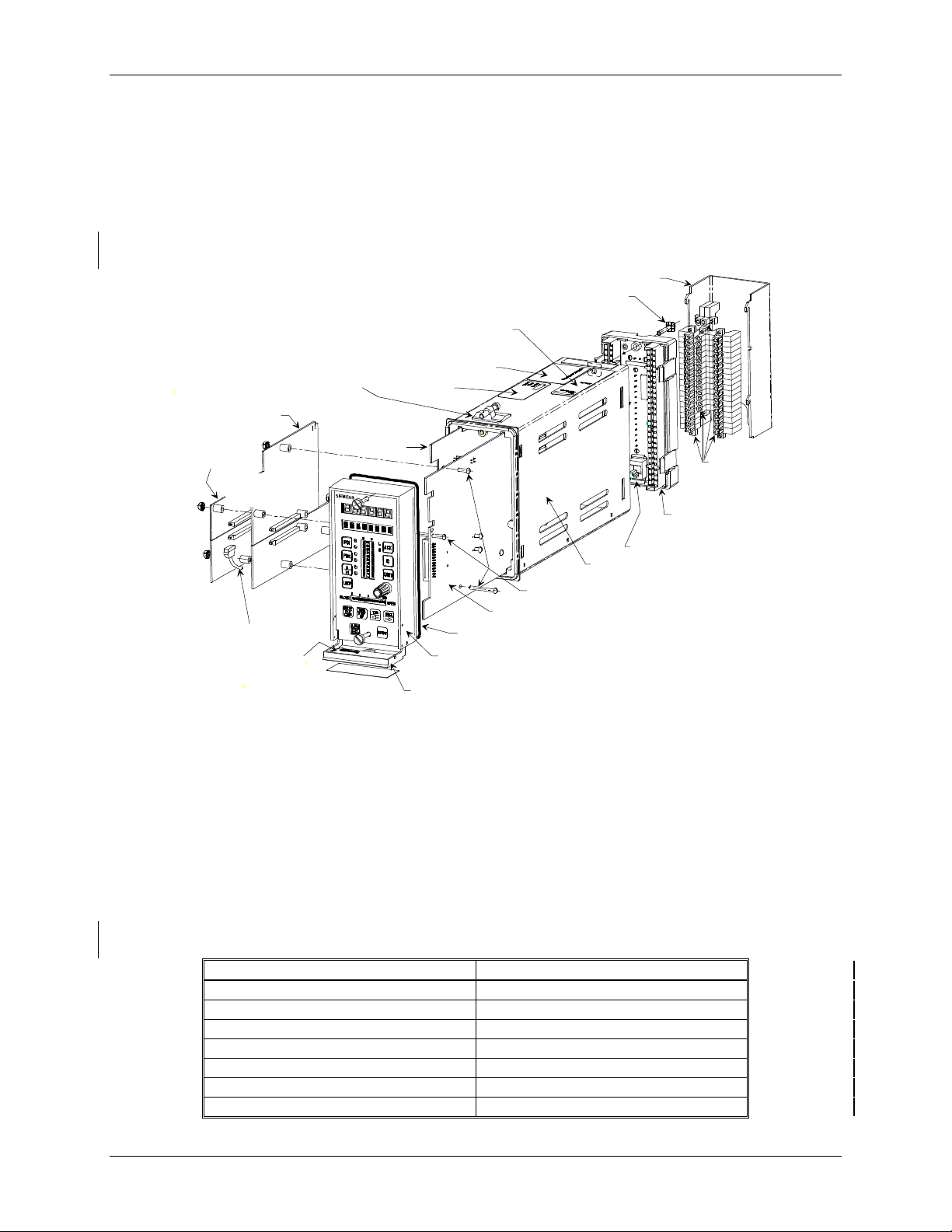
of continuous solutions and batch solutions. An exploded view of the controller appears in Figure 1-1.
At the heart of the Moore 353 is a powerful MPU Controller board that uses the latest in microprocessor
technology. It includes on-board I/O and reusable function blocks, and it is capable of solving a vast array of
control implementations including single loop, cascade, and dual loop. Available MPU board I/O is listed below.
Voltage Input, Approvals, and
Warning Label*
Warning and I/O
Capacity Label*
Nameplate*
I/O Expander
Board
MPU Controller Board
O-Ring, Display Assembly
Display Assembly with Operator Faceplate
Communication Port on Underside
Flip-Down Door with Loop ID Card
LIL or Ethernet
Network Board
RTC/CB or
RCB Board
Accessory or
Option Boards
Future
Use
Ethernet
Cable
Warning Label
Mounting Clip,
Top and Bottom*
LonWorks
Board
FIGURE 1-1 Moore 353, Exploded View
Modbus communication is standard and a port (RS485, half-duplex) at the rear terminals provides for network
connection of up to 32 controllers (e.g. Models 352P, 353, 354, 354N, and Procidia™ i|pac™) to an operator
workstation, Human/Machine Interface (HMI), or DCS, enabling integration of controllers into a plant-wide
system. A popular HMI is the Procidia i|station™ running i|ware PC™ operator interface software. A
communication port (RS232) on the underside of the Display Assembly is available for configuration and/or
debugging when using i|config™, the optional PC-based Graphical Configuration Utility.
An optional I/O Expander Board can be added to the base Moore 353. It includes direct thermocouple, RTD, and
frequency inputs and additional I/O for direct process measurement of temperature and frequency variables,
improving accuracy and control. Available Expander board I/O is listed below.
I/O on MPU Controller Board I/O on Expander Board
Analog Inputs 1, 2, and 3 Analog Input 4
Analog Outputs 1 and 2 Analog Output 3
Digital Inputs 1 and 2 Digital Inputs 3 and 4
Digital Outputs 1 and 2 ---
--- Analog Inputs Universal 1 and 2
--- Digital Inputs Universal 1 and 2
--- Relay Outputs 1 and 2
Connector Cover*
Ground Screw*
Removable
Portions of
Connectors*
Connector Socket
Assembly*
RJ-45 Ethernet Connector*
Case with Flange*
Mounting Kit, Accessory Boards
MG00392b
* = Case Assembly
1-2
October 2001
Page 17

UM353-1 Introduction
When even more I/O is needed for multiple-loop applications, advanced control, or batch sequencing, a remote I/O
option board that uses the popular LonWorks protocol can be installed. This LonWorks board provides
connectivity via a high-speed digital fieldbus to a large selection of standard I/O products: analog inputs and
outputs and digital inputs and outputs using relay or solid state technology.
Although the Moore 353 can be connected to and operated entirely from a central operator workstation, such as
i|station, a controller faceplate is included. This local operator interface is for applications where loops need
individual attention during startup, troubleshooting, maintenance, or emergency conditions. The convenient
faceplate layout and sophisticated software allow process and configuration changes to be made quickly and easily.
The controller can be completely configured from the operator faceplate or, as mentioned above, configured
remotely using i|config™, the optional PC-based Graphical Configuration Utility. An optional Real Time
Clock/Configuration Board (RTC/CB) is available to quickly transfer a configuration from one controller to
another when downloading a configuration over a network is not available. The RTC/CB also provides a real time
clock function.
Network communication options are listed in the following table.
Protocol (Select One) Available Connection Option Board Needed
Modbus Standard Rear Terminals, NCA and NCB None
Local Instrument Link Optional Rear Terminals, NCA and NCB LIL Communication
Ethernet Optional Rear Panel, RJ -45 (requires case option 4) Ethernet Communications
Modbus communication is standard. An optional Local Instrument Link (LIL) network board is available in place
of the Modbus communication to provide higher speed networking and peer-to-peer communication between
controllers. This provides connectivity with an array of network-enabled products, including those listed below.
Current Controller Models Previous Controller Models
Procidia i|pac Internet Control System
Moore 352P Single-Loop Digital Controller
Moore 354/354N Universal Controllers
Model 352 Single-Loop Digital Controller
Model 351 Triple-Loop Digital Controller
Model 382 Logic and Sequence Controller
An optional Ethernet board is available in place of Modbus and LIL communication. This option enables peer-topeer communication between Moore 353 controllers, Procidia i|pac controllers, and many other devices that feature
Ethernet (embedded Modbus RTU protocol). Ethernet communications requires an Ethernet board and controller
firmware V2.4 or higher.
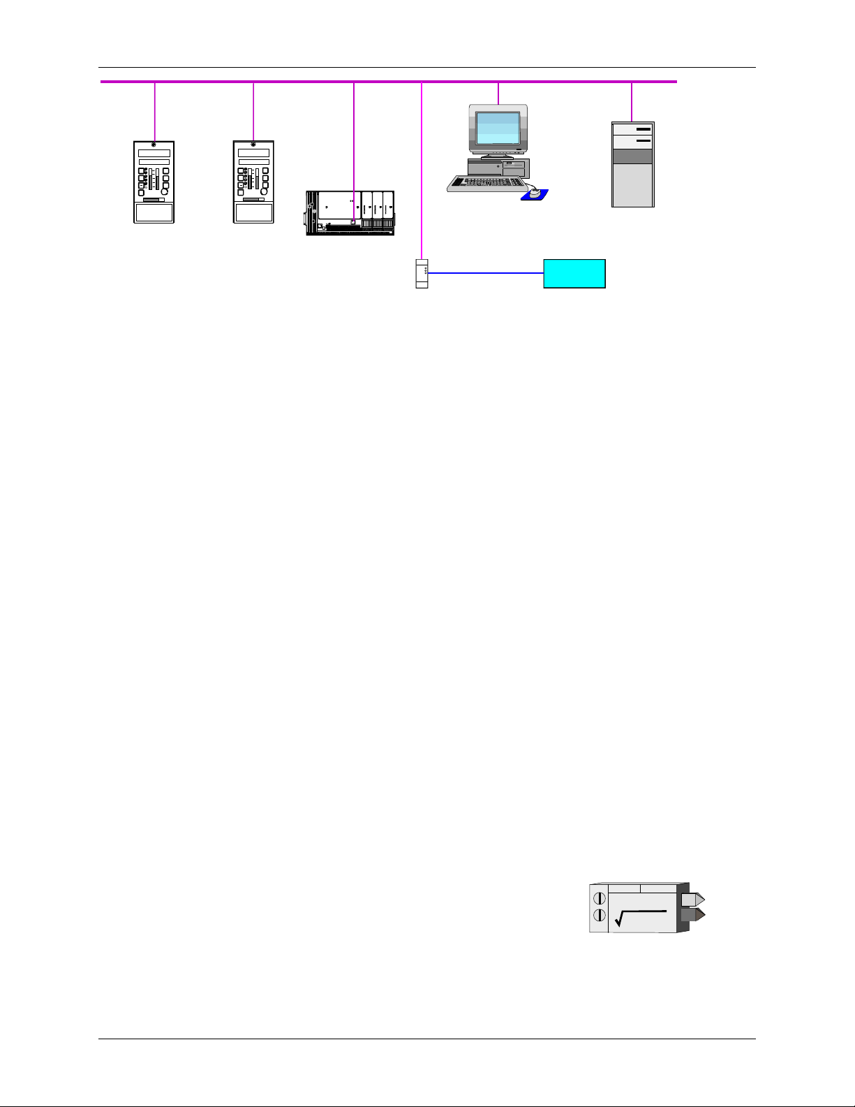
The Ethernet board supports uploading and downloading of controller configurations over the Ethernet LAN. For
example, if i|config Graphical Configuration Utility software is loaded on the local client shown in Figure 1-2,
controller configurations can be developed on the client, or uploaded from the controller for editing, and then
downloaded to the controller. Data can also be acquired from remote servers for the purpose of archiving and/or
data mining. The Ethernet-Modbus Bridge in Figure 1-2 accepts an Ethernet data command from the controller
and outputs an equivalent Modbus command to a Modbus device at address 1. The returning Modbus data is
embedded by the bridge in an Ethernet packet to be sent to the requesting controller.
Regardless of the selected communication option, the RS232 port on the underside of the Display Assembly will
communicate using Modbus. Controller hardware architecture is designed to accommodate other emerging fieldbus
technologies. This includes field communications that require lower power for intrinsic safety and higher speed for
interplant networking.
For small retrofit applications, the Moore 353 with operator faceplate is a replacement for a simple stand-alone
single-loop controller. It is easily upgraded with additional I/O and communication options for advanced control
strategies and plant networking.
October 2001 1-3
Page 18
Introduction UM353-1
Ethernet
s
4 2.453
2
TC2 0 5 3 . P
S P
100
L
PB1
ACK
S
80
60
D
PB2
40
A
20
UNITS
M
0
LOOP
100
0
| ||
|
CLOSE
OPEN
Moore 353
X03141S2
Multiple Moore 353 and Procidia i|pac Nodes,
each with an Ethernet Network Board.
s
4 2.453
2
TC 20 5 3 . P
S P
100
PB1
80
60
PB2
40
A
20
M
0
LOOP
0
| ||
CLOSE OPEN
Moore 353
L
ACK
S
D
UNITS
100
|
P3
X03141S2
P4
P1
13 5 7 9 111315 1 3 57 9111315 1 3 5 7 9111315
Local Client
Internal Web Server
Intranet
Modbus
Ethernet-Modbus
Bridge
Foreign Device with
Modbus Communications
MG00388a
FIGURE 1-2 Ethernet Architecture Example
Often in this publication, reference is made to the labels on the controller to ensure that the controller being
installed has the correct power input, I/O, communication options, and approvals. This is particularly important
when non-incendive requirements are present or a critical process is involved where a custom configuration or
calibration has been created. Label locations are shown in Figure 1-1 and typical labels are shown in Section 14
Model Designation and Specifications.
1.2 FUNCTION BLOCKS
Controller software is built on proven function block designs from previous LIL products and from Siemens
APACS® products that support the IEC1131 standard. In many cases, the controller has been enhanced with
features only now possible with state of the art technology.
Function blocks are selected for use within a LOOP. Multiple loops can be configured, and each loop can be
associated with an operator faceplate. Certain blocks are used once within each loop (e.g. controller, setpoint,
auto/manual), others can be used as many times as needed. Some notable features include Auto Tuning within the
PID function blocks, an expandable Sequencer that allows configuration of up to 250 steps, and up to 256 discrete
inputs and outputs. In addition, the Graphical Configuration Utility can be used to design the logic in a ladder
diagram. Combining these features with continuous control loops within the same controller offers a wellintegrated solution for small batch operations.
Several function blocks are available at the station level for configuration of STATION level parameters, such as
the station address and station tag name. Function blocks include the CLOCK block (when the RTC/CB option
board has been included), and the ETHERNET block (when the Ethernet board has been installed and the
controller contains firmware V2.4 or higher) to configure parameters such as the IP address. All other function
blocks are used for configuration within an individual LOOP. Control implementations are configured in the
Moore 353 by first creating a loop, then entering a unique loop tag name and selecting function blocks for use
within that loop. A number of loops can be configured in the Moore 353 and a number of function block types are
available as described in the sections that follow.
1.2.1 LOOP Function Block Types
Local I/O Function Blocks are provided on both the MPU Controller Board
and the I/O Expander Board. These blocks can be used in any LOOP, but as
fixed resources are expendable. When used within a loop, the unique block
AIN_+
AIN_c
name becomes <loop>.<block> (e.g. TC2053.AIN1 for Analog Input 1 used in
loop TC2053).
1-4
October 2001
AIN_
ANALOG INPUT
EXTRACTOR
QS
utput
O
O1
1
uality Status
Q
Page 19
UM353-1 Introduction
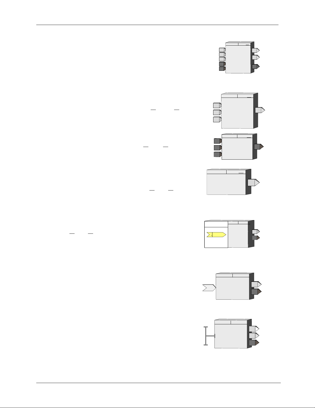
Fixed Loop Function Blocks can be selected for use within each configured LOOP and include those blocks which
define the major functions of a loop. The operator display function block (e.g.
ODC Operator Display for Controllers) defines the loop type, the function of
the local faceplate as well as the processing of commands coming from a
remote workstation. A single controller function block can be selected from
one of five available choices (ID, ON_OFF, PD, PIDAG, & PID) within each
loop. When used within a loop the unique block name becomes
Process
Setpoint
Feedback
Auto
P
S
F
A
IInitialize
ESN = 000
PID
PID
CONTROLLER
O1 Output
Absolute Error
AE
AT Warning
AW
<loop>.<block> (e.g. TC2053.PID for the PID controller used in loop
TC2053).
Arithmetic Function Blocks are also designated as LOOP function blocks
and can be used as many times as needed in each loop. Each use of a block
is automatically assigned a unique name (i.e. MATH01, MATH02) within
each loop so that the unique block name becomes <loop>.<block> (e.g.
TC2053.MATH01).
Input
Input
Input
A
B
C
A
B
C
MTH_ ESN = 000
MATH
ADD, SUB, MUL, DIV
O1 O
utput
Logic Function Blocks are also designated as LOOP function blocks and
can be used as many times as needed in each loop. Each use of a block is
automatically assigned a unique name (i.e. AND01, AND02) within each
loop so that the unique block name becomes <loop>.<block> (e.g.
TC2053.AND01).
Input
Input
Input
A
B B
C
AND_
A
C
AND
ESN =
000
utput
O1
O
General Purpose Function Blocks are also designated as LOOP function
blocks and include blocks that do not fall into the arithmetic or logic
categories. These can be used as many times as needed and each use will
HLD_
HOLD
ESN =
000
O1
Output 1
automatically be assigned a unique name (e.g. HLD01, HLD02) within each
loop so that the unique block name becomes <loop>.<block> (e.g.
TC2053.HLD01).
Remote I/O Bus Function Blocks can be used as needed in each LOOP to provide a method for sending and
receiving both analog and discrete data to and from remote devices over the
remote I/O digital bus. Each use will automatically be assigned a unique
name (e.g. AIP01, AOP01) within the station so that the unique block name
becomes <loop>.<block> (e.g. TC2053.AIP01 for Analog Input-lev_Percent
LONWorks
nviAIPnn1
nv *
SNVT_lev_percent
Network
AIP
ANALOG INPUT
LEV_PERCENT
O1
QS
Output 1
Quality Status
used in loop TC2053). The second AIP block used within the station will be
assigned AIP02 even if in a different loop so that the remote I/O blocks have
unique names within the station. This will enable unique names for station variables on the LON network.
LIL Global Function Blocks are used as needed within a LOOP when the LIL option board is installed to enable
global data communication over the LIL. They will automatically be
assigned a unique name (e.g. AIL01, DIL01) within each loop when it is
configured so that the unique block name becomes <loop>.<block> (e.g.
TC2053.AIL01). Input and output data blocks are available as needed and
ANALOG INPUT - LIL
LIL
GLOBAL
DATA
AIL_
O1
QS
Output
Output
O1
QS
will be assigned unique names as used (e.g. AIL01, AIL02 for Analog InputLIL blocks).
Ethernet Function Blocks (V2.4) are used as needed within a LOOP when
the Ethernet option board is installed They will automatically be assigned a
unique name (e.g. AIE01, DIE01) within each loop when it is configured so
that the unique block name becomes <loop>.<block> (e.g. TC2053.AIE01).
AIE_
ANALOG INPUT
ETHERNET
OR
O1
QS
Output
Output
Output
OR
O1
QS
1
1
October 2001 1-5
Page 20

Introduction UM353-1
1.2.2 Power Up Initialization
The Moore 353 will retain, in the station NVRAM, calculated block values (e.g. outputs, elapsed time, last
input/output logic states), including the time since power was lost. Three power up modes (hot, warm, and cold)
are utilized in the Moore 353 that affect the initialization of function blocks. These modes are configured by two
power up timers (warm and cold), included in STATION parameters. The station will initialize a hot start when
power up occurs prior to the expiration of the warm timer. A cold start will occur when power up occurs after the
expiration of the cold timer and a warm start will take place when the station powers up after the expiration of the
warm timer but prior to the expiration of the cold timer.
Hot Start1 - All function block execution continues from the last state prior to power fail.
Warm Start1 - Function blocks that have a power up in a last state feature, either by design or by configuration
selection, will power up as defined in the individual block descriptions. All other function blocks will initialize at
cold start conditions.
Cold Start1 - All function block outputs will initialize at 0 unless otherwise stated in individual block descriptions.
1.2.3 Configuration
The Moore 353 can be configured either locally or remotely. First, the local faceplate includes buttons located
behind a flip-down door for complete configuration including the addition/deletion of loops and function blocks
and the editing of function block parameters. Section 2 Configuration Overview includes a road map for stepping
through configuration. Certain block parameters (e.g. gains, constants) can be edited while on-line but design
changes (e.g. block interconnections, block additions) will put the station in “configuration hold” which will hold
outputs at the current value until the Exit button is pressed. This will enable bumpless changes to be made while
on-line.
The second method is to use the Graphical Configuration program. A
configuration can be downloaded to a controller either via the port on the local
faceplate or over a network (either Modbus, Ethernet, or LIL). During a
download, all outputs will be held and the controller will retain all the
intermediate calculations of all the blocks it had been running prior to the
download. After the download, all function block parameters with the same tag
name as those held will be used to initialize the downloaded function block
parameters, thus providing a bumpless download under these conditions. If a
loop tag name is changed, the tag names of all function blocks within that loop
will change and will, therefore, require re-initialization of all of these blocks.
However, the loop tag can be changed from the local faceplate without causing
re-initialization, providing a bumpless tag change.
Optional PC-Based
Graphical Configuration Software
X03145S0
1.3 PRODUCT SUPPORT
Product support can be obtained from a customer service center (i.e. Technical Support Group in North America or
a Technical Information Center (TIC) in Asia or Europe). Each region has a customer service center that provides
direct telephone support on technical issues related to the functionality, application, and integration of all products
supplied by the Process Industries Division of Siemens Energy & Automation. Regional contact information is
provided below. Your regional Technical Support Group or TIC is the first place to call when seeking product
support information. When calling, it is helpful to have the following information ready:
• Caller ID number, or name and company name - When someone calls for support for the first time, a personal
caller number is assigned. Having the number available when calling for support will allow the representative
taking the call to use the central customer database to quickly identify the caller’s location and past support
needs.
1
Set the Real Time Clock Jumper (W7 or W8) on the MPU Controller board. Refer to Section 9 Maintenance for details.
1-6
October 2001
Page 21

UM353-1 Introduction
• Product part number or model number and version
• If there is a problem with product operation:
- Whether or not the problem is intermittent
- The steps performed before the problem occurred
- Any status message, error messages, or LED indications displayed
- Installation environment
Customers that have a service agreement (ServiceSuite or Field Service Agreement) are granted access to the
secure area of the Siemens Internet site. This area contains a variety of product support information. When logging
on, you will be prompted to enter your username and password. All customers have access to the public portion of
the site.
TABLE 1.1 Contact Information
Telephone +1 215 646 7400, extension 4993
Fax +1 215 283 6358
E-mail MandCTechSupp@moore-solutions.com
NORTH AMERICA
ASIA
EUROPE
Hours of Operation 8 a.m. to 6 p.m. eastern time
Monday – Friday (except holidays)
Public Internet Site www.sea.siemens.com/ia/
Repair Service +1 215 646 7400 extension 4993
Telephone +011 65 299 6051
Fax +011 65 299 6053
E-mail TICGroupAP@moore-solutions.com
Hours of Operation 9 a.m. to 6 p.m. Singapore time
Monday – Friday (except holidays)
Public Internet Site www.sea.siemens.com/ia/
Repair Service +011 65 299 6051
Telephone +44 (0) 1935 470172
Fax +44 (0) 1935 470137
E-mail TICGroupEurope@moore-solutions.com
Hours of Operation 8:30 a.m. to 4:30 p.m. GMT/BST
Monday – Friday (except holidays)
Public Internet Site www.sea.siemens.com/ia/
Repair Service +44 (0) 1935 470172
1.4 EQUIPMENT DELIVERY AND HANDLING
1.4.1 Factory Shipment
Prior to shipment, a controller is fully tested and inspected to ensure proper operation. It is then packaged for
shipment. Most accessories are shipped separately.
1.4.2 Receipt of Shipment
Inspect each carton at the time of delivery for possible external damage. Any visible damage should be
immediately recorded on the carrier’s copy of the delivery slip.
Carefully unpack each carton and check the contents against the enclosed packing list. Inspect each item for any
hidden damage that may or may not have been accompanied by exterior carton damage.
October 2001 1-7
Page 22

Introduction UM353-1
If it is found that some items have been damaged or are missing, notify the Process Instrumentation Division of
Siemens Energy and Automation immediately and provide full details. In addition, damages must be reported to
the carrier with a request for their on-site inspection of the damaged item and its shipping carton.
1.4.3 Storage
If a controller is to be stored for a period prior to installation, review the environmental specifications in Section 14
Model Designation and Specifications.
As shipped, the MPU Controller board Real Time Clock Jumper (W7 or W8) is set to maximize battery life. If the
jumper has been set to enable Hot/Warm Start, or to confirm that the jumper is properly set, refer to Section 11
Maintenance and set the jumper for storage.
1.4.4 Typical Shipment Contents
The items listed below are those typically included in a shipment and are subject to change.
1. Moore 353 Process Automation Controller, model number per order, qty. 1
2. Power Input and Range Resistor Kit, PN 16354-30, qty. 1
DESCRIPTION QUANTITY
Resistor, 250Ω, 0.1%, 3W, WW
Sleeving 3
Crimp-On Connector 6
Kit Installation Instruction 1
3
3. Mounting Clip Kit, no part number, qty. 1
Contents: 2 Mounting Clips and 2, 8-32 x 1 Screws (see the Parts List at back of this manual for part numbers)
4. I/O Expander Board Kits
PN16353-52 I/O Expander Board Kit - The I/O Expander Board is factory installed when a Moore 353 with
Expansion Board option 1 is ordered.
• When adding an I/O Expander board to a Standard Case (case Option 2, with black Side Entry
Connectors), order connector kit PN 16353-133 to obtain terminals 27-52.
• When adding an I/O Expander board to a Standard Case with Ethernet connector (case Option 4, with
gray or green Direct Entry Connectors), no additional connectors need be ordered.
• For field installation of this kit, see the supplied Kit Installation Instruction (15900-390).
DESCRIPTION QUANTITY
I/O Expander Board - Do not remove Board from static shielding
1
bag until it is to be installed.
Range Resistor and Reference Junction Kit, see below 1
PN16353-49 Range Resistor and Reference Junction Kit - This kit is supplied with the above I/O Expander
Board Kit and with a factory shipped Moore 353 with Expansion Board option 1.
1-8
October 2001
Page 23

UM353-1 Introduction
DESCRIPTION QUANTITY
4-20 mA to 1-5V Range Resistor, 250Ω, 0.1%, 3W, WW
4-20 mA to 15-75 mV Range Resistor, 3.75Ω, 0.1%, 3W, WW
1
2
Sleeving 5
Crimp-On Connector 6
TC Reference Junction, 100Ω
2
Kit Installation Instruction 1
5. UM353-1, Moore 353 User’s Manual (this manual), qty. 1
6. Additional items as required by your order. Refer to the packing list accompanying a shipment.
n
October 2001 1-9
Page 24

Introduction UM353-1
1-10
October 2001
Page 25

UM353-1 Configuration Overview
2.0 CONFIGURATION OVERVIEW
Configuration enables a user to select function blocks, stored in the controller, from an available list and enter
appropriate block parameters to implement a specific control strategy. Although configuration affects the entire
station, the controller partitions related control implementations into LOOPS. A maximum of 99 loops can be
configured and 25 can have operator displays that are mapped to network communications2.
Each LOOP can contain the function blocks listed in the following paragraphs. Signals can be connected between
function blocks within the LOOP as well as between loops. Also, there are several STATION function blocks that
are fixed and available in the STATION menu for setting station related values.
Section 3 fully describes all available function blocks. For tuning guidelines refer to Section 9.2 Autotune
Procedure or request AM-35 Digital Controller Tuning.
NOTE
This User’s Manual includes the functionality provided by MPU Controller Board
firmware Versions 1.3 and 2.0 through 2.40. These enhancements appear mainly in
Sections 2 and 3. They are identified by the phrase “in version 1.3 and higher” or simply
2.1 STATION FUNCTION BLOCKS
Function blocks that are permanent and accessible at the STATION menu level:
FCO LIB .......... Factory Configured Options Library
STATN ............. Station Parameters
SECUR............. Security
CLOCK............ real time CLOCK (requires firmware V2.2 or higher and RTC/CB board
ETHERNET..... Ethernet Communications (requires firmware 2.4 and Ethernet board)
2.2 STATION HARDWARE I/O BLOCKS
Function blocks that are available during configuration depend on the hardware installed in the controller. These
blocks can be selected within a LOOP but as fixed resources, once selected, are no longer available. The left
column shows the minimum and maximum quantities of each block and the right column shows the quantity for
each circuit board.3
AIN1-4 ............ Analog Input .................................MPU Controller Board (3), I/O Expander Board (1)
AINU1-2 ...........Analog Input, Universal ................I/O Expander Board (2)
AOUT1-3.......... Analog Output ..............................MPU Controller Board (2), I/O Expander Board (1)
DIN1-4 ............. Digital Input.................................. MPU Controller Board (3), I/O Expander Board (1)
DINU1-2 ...........Digital Input, Universal.................I/O Expander Board (2)
DOUT1-2.......... Digital Output...............................MPU Controller Board (2)
ROUT1-2.......... Relay Output.................................I/O Expander Board (2)
2.3 LOOP FUNCTION BLOCKS
The following blocks are available as needed within each loop in the quantities indicated (the quantity is one if no
number is shown). Some blocks (e.g. A/M, BIAS) can be used only once within each LOOP. Others (e.g. ADD)
are reusable within a LOOP and can be used up to the maximum number indicated. Each time a reusable block is
selected within a LOOP, a new instance number will automatically be assigned (i.e. ADD01, ADD02). Each
LOOP can have one operator display block (i.e. ODC or ODS). The display block defines how the loop will be
2
Subject to available memory in the controller.
3
Model 352Plus only: Although these blocks can be selected in configuration, some may not have physical connections to the rear terminals
depending upon the positioning of the Option 3 I/O Jumper.
October 2001
2-1
Page 26

Configuration Overview UM353-1
displayed on the local faceplate when that loop is selected and also how loop data will be mapped on the Modbus or
LIL network interface. Each LOOP can have one controller function block (i.e. ID, ONOFF, PD, PID, or PIDAG).
A/M................... Auto/Manual
ACS01-99.......... ARCCosine (V1.3)
ADD01-99......... Addition
AG3 .................. AGA3 (V1.3)
AG7 .................. AGA7 (V1.3)
AG8 .................. AGA8 (V1.3)
ALARM............ Alarm
AND01-99......... AND Logic
ASN01-99.......... Arcsine (V1.3)
ATN01-99......... Arctangent (V1.3)
ATD01-99......... Analog Trend Display (V1.3)
BATOT............. Batch Totalizer
BATSW............ Batch Switch
BIAS................. Bias
CHR01-99......... Characterizer
CMP01-99.........Comparator
COS01-99 ......... Cosine (V1.3)
DAM01-99........ Deviation Amplifier
DIV01-99 .......... Division
DNC01-99......... Divide by N Counter
DTM01-99 ........ Dead Time Table
DYT01-99......... Delay Timer
E/I..................... External/Internal Transfer
ESL................... Events Sequence Logger (V1.3)
EXP01-99.......... Natural Exponentiation (V1.3)
EXT01-99 .........Exponentiation (V1.3)
FTG01-99 .........Falling Edge Trigger
GB01-99............ Gain & Bias
HLD01-99......... Hold
ID...................... ID Controller
LL01-99............ Lead/Lag
LMT01-99 ........ Limit
LN_01-99.......... Natural Logarithm (V1.3)
LOG01-99......... Logarithm Base 10 (V1.3)
MTH01-99........ Math
MUL01-99 ........ Multiplication
NND01-99......... NAND Logic
NOR01-99......... NOR Logic
NOT01-99......... NOT Logic
ODC.................. Operator Display for Controllers
ODS...................Operator Display for Sequencers
ODA (V2.2).......Op Disp for Analog Ind. & Alarm
ODD (V2.2).......Op Disp for Discrete Ind &
Control
ODP (V2.2)........Operator Display for Pushbuttons
ONOFF .............ON OFF Controller
OR01-99............ OR Logic
ORSL................Override Selector
OST01-99..........One Shot Timer
PB1SW.............. PB1 Switch
PB2SW.............. PB2 Switch
PB3SW.............. PB3 Switch
PCOM...............Phase Communication (V1.3)
PD...................... PD Controller
PID.................... PID Controller
PIDAG ..............PIDAG Controller
PRSEQ..............Program Sequencer
QHD01-99.........Q uickset Hold
RATIO..............Ratio
RCT01-99..........Repeat Cycle Timer
RLM01-99.........Rate Limiter
ROT01-99 .........Retentive On Timer
RSF01-99........... RS Flip-Flop
RTG01-99 .........Rising Edge Trigger
RTT01-99.......... Real Time clock Trip (V2.0)
SCL01-99 ..........Scaler
SEL01-99...........Signal Selector
SETPT...............Setpoint
SIN01-99 ...........Sine (V1.3)
SPLIM...............Setpoint Limit
SRF01-99........... SR Flip-Flop
SRT01-99 ..........Square Root
SUB01-99 ..........Subtraction
TAN01-99..........Tangent (V1.3)
TH01-99............ Track & Hold
TOT01-99.......... TOTalizer (V2.3)
TSW01-99 .........Transfer Switch
XOR01-99......... Exclusive OR Logic
2.4 LIL GLOBAL DATA I/O FUNCTION BLOCKS
These function blocks are available in the quantities indicated within each loop when the optional LIL Network
board is installed. The total number of global function blocks will be limited by the number of global channels
available. A controller has 256 channels. Each global data block occupies one global channel. In addition, each
configured Control LOOP occupies 5 channels, each configured Sequencer LOOP 6 channels, and the Station itself
the first 7 channels. See Section 6 for more information on network communications.
AIL01-99 .......... Analog Input_LIL
AOL01-99......... Analog Output_LIL
DIL01-99 ......... Discrete Input_LIL
DOL01-99......... Discrete Output_LIL
2-2
October 2001
Page 27

UM353-1 Configuration Overview
2.5 ETHERNET DATA I/O FUNCTION BLOCKS
These function blocks are available in the quantities indicated within a controller when the optional Ethernet
Network board is installed. These blocks can be selected for use within individual loops but block names are
unique station wide.
AIE01-32 .......... Analog Input - Ethernet (V2.4)
AOE01-32......... Analog Output - Ethernet (V2.4)
CIE01-32 .......... Coil Input - Ethernet (V2.4)
DIE01-32 .......... Discrete Input - Ethernet (V2.4)
DOE01-32......... Digital Output - Ethernet (V2.4)
2.6 LonWorks REMOTE I/O FUNCTION BLOCKS
These function blocks are available in the quantities indicated within a controller when the optional LonWorks
Remote I/O board is installed. LonWorks is available for use with Models 352P, 353 and 354 controllers. These
blocks can be selected within individual loops, but block names will be unique station wide. This allows
LonWorks network managers that identify variables using the block name within an individual node to be unique.
For example, if LOOP01 uses AIP01 and AIP02 and an AIP block is selected in LOOP02 the name will be AIP03.
Detailed information on the use of LonWorks can be found in Section 5. Model 352P only: Select LonWorks by
setting the Option 3 I/O Jumper.
AIP01-25........... Analog Input lev_Percent
AOP01-25......... Analog Output lev_ Percent
DID1-6.............. Digital Input lev_ Discrete, 16 Channels
DIS1-6............... Digital Input_State (V1.3)
DOD1-6.............Digital Output lev_Discrete, 16 Channels
DOS1-6............. Digital Output_State (V1.3)
2.7 CONFIGURATION PROCEDURE
Each controller must be configured to perform the desired control strategy. The arrangement of functions and the
numerical data required for a particular control circuit are referred to as the controller configuration. Local and
remote configurations are accommodated.
Local configuration involves the configuration pushbuttons and the pulser knob on the Display Assembly’s
faceplate. Section 9.2 Configuration Mode shows the faceplate and provides brief descriptions of control functions.
Remote configuration requires a personal computer running the i|config™ Graphical Configuration Utility and
either a configuration cable or a Modbus, LIL, or Ethernet network connection. The configuration can be created
at and downloaded from the personal computer. A network connection is made at the controller’s terminals. The
configuration cable plugs into the configuration port in the underside of a 352Plus or 353 Display Assembly or into
a 354N DB9 connector. The other end of this cable connects to a personal computer’s serial port or to a modem.
Explosion hazard
Explosion can cause death or serious injury.
In a potentially explosive atmosphere, remove power from the
equipment before connecting or disconnecting power, signal
or other circuits.
Comply with all pertinent regulations regarding installation in
a hazardous area.
WARNING
October 2001
2-3
Page 28

Configuration Overview UM353-1
A configuration is designed by first arranging the needed function blocks in a fashion similar to that of a PI & D
drawing. Parameter and calibration values are determined next and then entered on a Configuration
Documentation Form or into the Graphical Configuration software. The controller may then be configured locally
by entering the information on the form into the controller’s configuration memory or remotely by downloading
directly from the personal computer.
Nine common controller configurations have been stored in a built-in library that can be entered from the FCO LIB
function block at the STATION level. Simple changes can then be made to accommodate individual needs. As an
example, FCO101 Single Loop Controller includes the setpoint tracking feature but by simply disconnecting the
TC input to the SETPT function block, it becomes a fixed setpoint Single Loop Controller. These FCOs are fully
documented in Section 4.
FCO101 - Single Loop Controller w/ Tracking Setpoint
FCO102 - Single Loop Controller with Fixed Setpoint
FCO103 - External Set Controller with Tracking Local Setpoint
FCO104 - External Set Controller with Non-Tracking Local Setpoint
FCO105 - Ratio Set Controller with Operator Setpoint Limits
FCO106 - Single Loop Controller w/Operator Setpoint Limits
FCO107 - Dual Loop Controller
FCO121 - Cascade Loop Controller
FCO122 - Cascade Loop Controller with Operator Setpoint Limits
Unless otherwise specified on the order, FCO101 is installed at the factory. Use the following procedure to change
the factory configured option. Refer to Figure 2-1 Configuration Road Map to move to, and then through, the
selected FCO and to enter or edit parameter values.
1. Press the ENTER/EXIT CONF button. LOOP will appear on the alphanumeric display.
2. Rotate the Pulser Knob until STATION appears on alphanumeric display.
3. Press the STEP DOWN button to display FCO LIB.
4. Press the STEP DOWN button to display FCO in the lower display.
5. Press the STEP DOWN button until the desired FCO number appears in numeric display.
6. Rotate the Pulser Knob to display the desired FCO number in the upper display.
7. Press the STORE button to load the new FCO.
8. Edit the FCO as needed. In addition to the material in this section, refer to:
• Section 3 Function Blocks for details about configurable parameters
• Section 4 Factory Configured Options for FCO diagrams and parameters
• Sections 6 and 7 for Modbus, LIL, or Ethernet mapping
• Section 9 Operation for operating controls and displays
Where an FCO is not suitable, a complete configuration can be designed to suit individual needs. Section 4 can be
used as a guide for documenting a user-created or used-edited configuration. i|config, a PC-based Graphical
Configuration Utility, can be used to design, document, and save configurations as well as download them to the
controller, through either the configuration port or using a Modbus, LIL, or Ethernet network connection.
The above steps are illustrated in Figure 2-1 Configuration Road Map. The map also provides a broad overview of
the configuration procedure.
• Press the ENTER CONF button to enter the configuration mode. Press the button again to exit configuration.
• After entering the configuration mode, LOOP or STATION can be selected.
2-4
October 2001
Page 29

UM353-1 Configuration Overview
• At the STATION level, a factory configured option can be loaded, station parameters can be configured,
security passwords can be entered, the clock can be set, communication parameters can be configured, and
inputs and outputs can be calibrated.
• Calibration can also be performed within individual loops containing the input or output function blocks used
in the LOOP.
• At the LOOP level, new loops can be added, loops can be deleted, or an existing loop can be edited.
When a new loop is created, the controller will assign a default name (e.g. LOOP01). The loop name can be
changed to any valid 12-character ASCII value. It is suggested that loop names be limited to 6-characters so that
the complete tag name will appear in the alphanumeric display during normal operation.
A Loop can be edited by stepping down from the EDIT menu. If more than one loop has been configured, press
the STEP DOWN button and turn the Pulser Knob to step through the list of configured loops. From the selected
loop, stepping down will provide various options within the specific loop.
• The current value of all configured block outputs can be viewed.
• The current tag name of the loop and the ESN (Execution Sequence Number) can be changed. ESNs are
automatically assigned by the controller in the order of creation, either a loop or individual block. An ESN
should be changed when it is important that one loop be executed prior to another (e.g. cascade primary
executes prior to the cascade secondary).
• Function blocks can be added to or deleted from the loop. Existing function blocks can be edited. Use the step
up and step down buttons to move between the function block, parameter, and value levels within the EDIT FB
menu.
If no configuration entries are made for about three minutes, the mode will time out and the controller will exit the
configuration mode. The STATN function block has a CONFG TO (Configuration Timeout) parameter to enable
or disable timeout.
Loading an Earlier Firmware Version
In rare instances, replacing the installed MPU Controller board firmware with an earlier version may be desired.
Before loading the earlier firmware, refer to the sections on configuration and load FCO-0 (zero) as the active
configuration. This will install a minimum configuration and will reduce the number of error messages that appear
during the firmware loading process.
2.8 OPERATION DURING LOCAL ON-LINE CONFIGURATION
Changing a controller’s configuration parameters while the station is on-line can affect its operation and output
values. Configuration parameters are divided into four types: HARD, SOFT, READ, and CALIBRATION.
HARD - When a HARD parameter is STORED the controller will suspend execution of all function blocks and
will hold all outputs until the EXIT button is pressed. A HARD parameter is identified with each ‘(H)’ notation in
a function block parameter listing in Section 3. When a loop or function block is added or deleted, the station
enters a HARD configuration mode.
SOFT - A SOFT function block parameter can be changed while the function blocks are executing. A SOFT
parameter is identified with each ‘(S)’ notation in a function block parameter listing in Section 3. All QUICKSET
changes also fall into this category.
READ - These parameters are not changeable and therefore can be read while the station function blocks are
executing. A READ parameter is identified with each ‘(R)’ notation in a function block parameter listing in
Section 3. The configuration VIEW mode also falls into this category.
CALIBRATION - When entering the CONFIGURATION mode, the station will suspend execution of all function
blocks and will hold all outputs until the EXIT button is pressed. If an output block is being calibrated its output
October 2001
2-5
Page 30
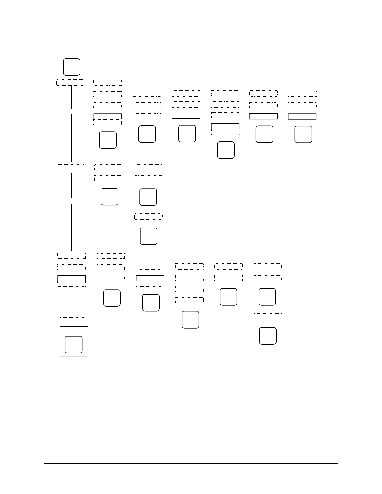
Configuration Overview UM353-1
will be adjusted during the calibration procedure. A CONFIGURATION parameter is identified with each ‘(C)’
notation in a function block parameter listing in Section 3. The calibration mode can be entered from the
individual block or from the CAL mode at the station level.
ENTER
EXIT
CONF
|
LOOP
<>
X
X
STATION
X
FCO LIB
X
FCO
X
~
101
FCO
|
STORE
<>
STA TN
X
TAG
X
PAC 353
|
STORE
<>
<+>
SECURITY
X
LEV1 COM
X
~
000000
|
STORE
<>
<+>
CAL
X
AIN1
X
CAL ZERO
X
CAL
CAL ZERO
|
STORE
<+>
<+>
<>
CLOCK
X
SET TIME
x
11:00
|
STORE
<>
<+>
ETHERNET
X
IP ADRES
x
4 176
|
STORE
<+>
EDIT
TC2053
PID.O1
Key:
X
X
VIEW
X
325.80
TC2053
325.80
<>
ADD DELETE
X
~
LOOP01
|
STORE
<>
FC2367
<> <>
EDIT TAG
X
<+>
TC2053
|
STORE
Alphanumeric Display
Numeric Display
Configuration Pushbutton
<>
<+>
X
TC2053
|
STORE
|
CONFIRM
|
STORE
EDIT ESN
X
~008
LOOP ESN
|
STORE
<+>
<> <>
EDIT FB ADD FB
X
A/M
X
RG PTR
X
PID
|
STORE
<+>
<+>
<+>
ADD01X<+>
|
STORE
<>
DEL FB
X
A/M
|
STORE
|
CONFIRM
|
STORE
<+>
~
008
<> Turn Pulser to select new parameter or value (move horizontally across map)
<+> Turn Pulser to select additional menu items
X Use Step Up or Step Down pushbutton (move vertically across map)
Display with changeable value (turn Pulser knob)
X03137S2
FIGURE 2-1 Configuration Road Map
n
2-6
October 2001
Page 31

UM353-1 Function Blocks
3.0 FUNCTION BLOCKS
This section contains a detailed description of each function block (FB) available for configuration4. Each function
block description is supplemented by: (1) a drawing of the block showing data inputs and outputs and control lines,
(2) a block parameter table. Most blocks are further described by a block diagram that shows the block’s circuitry
in a simplified or equivalent circuit form.
NOTE
This User’s Manual includes the additional functionality provided by MPU Controller
Board firmware Versions 1.3, and 2.0 through 2.40. These enhancements appear mainly
in Sections 2 and 3. They are identified by the phrase “in firmware 1.3 and hi
the two-digit firmware version (e.g. “V1.3” or "V2.4") in text.
Function blocks have three types of inputs/outputs: digital, analog, and special data structure.
1. Arrows with dark shading and white letters are digital (outputs are displayed as 0 and 1 in the VIEW mode
when using the local faceplate). Digital outputs are typically used to designate function block status, logical
outputs, and on/off function block outputs. Some examples are:
• Function block status: E/I status (IS, ES, SI), A/M status (AS, NA, MS, ES, SS), and Quality Status (QS)
• Logical Outputs: AND (01), OR (01), NOR (01), or NOT (01)
• On/Off function blocks: One Shot Timer (01), Retentive On Timer (01), Rising Edge Trigger (01),
Alarms (A1, A2, A3, and A4), and Comparator (01)
2. Arrows with medium shading and black letters are analog. Internally they are REAL floating point numbers
and outputs of these types will be displayed in the VIEW mode when using the local faceplate with the decimal
point located to allow greatest resolution between 0.00000 and 999999 or -0.0000 and -99999. Numbers
outside this resolution will blink.
Analog outputs are typically output (01) for analog I/O blocks and math functions. Analog outputs may also be
specific to a particular function block such as the Analog Output (AO), Step Number (SN), Step Time (ST),
Remaining Time (RT), and Current Recipe (CR) outputs of the Program Sequencer.
3. Arrows with medium shading and black letters but with a white tip are special data structures for range scaling
information and will not be displayed in the VIEW mode). Range scaling information is used when there is a
conversion of units within a function block, for example, the Alarm block scales the alarm limits into process
engineering units when the range pointer is configured to the process analog input block. If unconfigured the
units default to 0-100%. The output range (OR), typically used on analog output function blocks, includes
MIN and MAX SCALE, the DPP (Decimal Point Position), and the ENGUNITS (Engineering Units). The
analog output block is typically used for a 0-100% output to a valve where a minscale of 0 = 4 mA output and
a max scale of 100 = 20 mA output.
The output range is connected to the Range Pointer (input R) of functions blocks requiring scaling other than
the default 0-100. For example, an Analog input block could be scaled 0-5000 psig with output (01) connected
to the AOUT input (S) and the AIN (OR) connected to the AOUT input (R). The Analog output would then
output 4 mA at a minscale of 0 psig and 20 mA at a maxscale of 5000 psig. In contrast, if AOUT input (R)
were left unconfigured the output would equal 4 mA at a minscale of 0 psig, 20 mA at a maxscale of 100 psig
and over ranged for any input over 100 psig.
Some users may prefer to use normalized 0-1 analog inputs for math calculations and scale outputs for display
only; in this case, the Scaler function block may be used to provide an output range (OR) for the ODC
(Operator display block).
4
The LonWorks function blocks used in Models 352P, 353, and 354/354N are described in this manual. The Ubus function blocks used in
ProcidiaTM (UAH, UAI, UAO, UDI, UDO, UEI, UER, UET, URI, USD, and UTI) are included in the firmware but are not described here since
they will not operate in Models 352P, 353, and 354/354N.
October 2001
3-1
Page 32

Function Blocks UM353-1
Note how the range pointers are used in the following Factory Configured Options (FCOs). FCOs are
described in detail in the Factory Configured Options section.
• FCO101 Single Loop Controller – The process output range AIN1 (OR) is connected to the range pointer
of the SETPT block, the PID block, the ALARM block and the process variable range of the ODC block.
As a result these blocks will be automatically rescaled when the minscale and the maxscale or the
engineering units of the Process is changed. For example, if AIN1 is scaled 0-5000, the 0-100% bargraph
on the display will represent 0-5000 when displaying the process. The A/M block, AOUT1 (Valve)
output, and the Valve input of the ODC block are scaled based on the output of the PID block.
• FCO104 External-Set PID controller – The external setpoint is displayed as variable X in the ODC block.
Therefore, the ODC (RX) input uses the range output of the external setpoint AIN2 (OR) for scaling. The
0-100% bargraph will represent the range of AIN1 when displaying the process variable and the range of
AIN2 when displaying the X variable.
• FCO105 Ratio Set Control – AIN1 and AIN2 are scaled 0-100% of flow. The ratio of these flows is
displayed on variable Y and the scaler function block is used to define the engineering units as a
dimensionless ratio CF/WF scaled from 0.50 –1.50.
Connections between blocks are allowed only with similar data types.
To help you quickly locate a function block:
• In this section, function blocks are listed alphabetically by the block ID (e.g. AIN for Analog Input).
• In Section 2, function blocks are listed by broad function (e.g. station hardware I/O).
3-2
October 2001
Page 33

UM353-1 Function Blocks
3.1 STATION FUNCTION BLOCKS
Station function blocks include factory configured options (FCOs), security, and station parameters. Each is
described in the following subsections.
3.1.1 FCO LIB - Factory Configuration Library
The FCO LIB function block provides a selection of preconfigured applications. An FCO can be selected from
the library and “STORED”. This loads a complete
controller configuration, as defined by the FCO
documentation, and erases any previously stored
configuration. Station parameters and Calibration are
retained when a new FCO is loaded. This enables a user
to quickly configure the controller with an FCO without
having to re-calibrate or re-enter the Station parameter
values.
Upon stepping down to the FCO parameter, the last
FCO that was loaded in the controller will be displayed.
Turning the pulser knob will then display other FCOs that are available in the FCO library.
The configuration installed at the factory will be either FCO 101 or a custom configuration that was ordered and
defined by the user. FCO 101 is a basic single loop PID controller.
An FCO can be loaded at any time in the field and used as is or modified (edited) to meet individual requirements.
The FCO library file is not modified when the FCO selected for controller configuration is edited.
FCO LIBRARY
C
OF
FCO LIB
FCO 02
FCO 04
FCO 05
FCO 06
FCO 07
FCO 08
FCO 09
FCO 03
FCO 01
FCO LIBRARY
actory Configured Option
F
(H)
....... 0 - 999999 (00)
3.1.2 SECUR - Security
The SECUR function block enables a user to lock out
portions or all of the faceplate configuration functions.
Five levels of security are available; see Table 3.1.
Each level is factory set to 000000 (no security), and
can be changed by the user in the field to any number
up to 999999.
A security combination should be assigned to each
security level (1-highest, 5-lowest). A level that
remains at the default 000000 combination will have
no security for the involved function(s) regardless of
the security assigned to the other levels. For example,
assume that level 1 is assigned a security combination
but level 4 remains at 000000. If a controller
calibration is performed, the station will not prompt
the user for the security combination and anyone will
be able to store new calibration values.
If security is desired, it is recommended that all 5 levels of security be set with either the same value or different
values when different individuals are granted access to only certain functions.
The functions that can be accessed at the various security levels are listed in Table 3.1. The security combination
will be required when the user attempts to store a parameter or attempts to view a security combination. The
SECURITY
1
2 MC OE VL
3 MC OE VL
4 MC OE VL
5 MC OE VL
SECUR
SECURITY
el 1
MC OE VL
LEV
COM
el 2
LEV
COM
el 3
LEV
COM
el
LEV
4 COM
el 5
LEV
COM
(S)
bination
.... 000000-999999 (000000)
(S)
bination
.... 000000-999999 (000000)
(S)
bination
.... 000000-999999 (000000)
(S)
bination
.... 000000-999999 (000000)
(S)
bination
.... 000000-999999 (000000)
October 2001
3-3
Page 34

Function Blocks UM353-1
faceplate alphanumeric will display “ENTR COM” and allow the user to enter and store the combination. A
combination is entered by selecting one digit at a time using the ß and à keys and setting the number for that
digit using the pulser. When all digits have been set, press STORE. If incorrect, the alphanumeric will display
“ACCESS/DENIED” and then return to the parameter level. Once a combination has been entered correctly,
access will be provided for all functions within that level until the user exits configuration. If a combination is lost,
contact Siemens technical support to obtain a method to enter configuration and change the security codes. Refer
to Section 1.3 for the contact information.
The PC-based Graphical Configuration Software may also have security options similar to the above. However,
there is no security in the download procedure itself. At the controller there are parameters in function block
STA_PARM that will lock out all downloads and all parameter writes from a PC.
TABLE 3.1 Security Level vs. Accessible Operations
FUNCTION LEVEL 1 LEVEL 2 LEVEL 3 LEVEL 4 LEVEL 5
Station Function Block Edit X X
Loop/Function Block Add/Delete X X
Loop/Function Block Edit X X X
Security Configuration X
Calibration of Input/Outputs X X
Quick Faceplate Access* X X X X
Configuration of NEW FCO X X
Change CLOCK X X
* Security does not apply, in firmware versions 1.30 and higher, to continuously adjustable quickset parameters
that include RATIO, BIAS, and QHLD.
3-4
October 2001
Page 35

UM353-1 Function Blocks
3.1.3 STATN - Station Parameters
The STATN function block enables entry of station
identification and other station related information.
When the station is networked using Modbus or the LIL
option board the address is used by higher level devices
to obtain information from the station. LIL addresses
range from 1-32 or 1-64 when a Model 321 Expansion
Satellite is used. Modbus can range from 1-250 but
normally 1-32 is used to correspond to the total number
of devices that can be installed on a single network.
Once the address has been assigned and higher level
devices have been configured to access information from
the station, changing the address can require
reconfiguration of the higher level device. There may
also be higher level devices that will query and assign
addressing information based on the station tag name.
In this case, a tag name change will also require
reconfiguration of higher level devices. Therefore, it is
important not to change the station identification
without being aware of system consequences.
There are two timers used during power up
initialization: WARM TIM and COLD TIM. The
station takes approximately 8 seconds to perform power
up initialization before the power up time is evaluated.
A timer should be set to a value greater than 8 seconds
to be effective. A timer setting of 0 will be considered as
infinite (e.g. to always power up hot, set the warm timer
to 0). When the station powers up after a loss of power but prior to the expiration of the warm timer, the station
will execute a Hot Start. If the station powers up after the warm timer expiration but prior to the expiration of the
cold timer, the station will execute a warm start. In all other cases, the station will execute a cold start. The
adjustable range of these timers is 0-18000 seconds for firmware versions prior to than 1.30 and is 0-999999
seconds for versions 1.30 and higher. IMPORTANT: The Real Time Clock jumper must be set for the warm and
hot timers to function. See the Maintenance section for details on this jumper.
When using Modbus Network communications, the WATCHDOG timer can be set to a value other than 0 to cause
a high WD output from the loop operator display function block when the station does not receive a computer
command within the timer period. A value of 0 disables the watchdog. A Modbus communications DELAY time
can entered for both the Display Assembly configuration port and LIL/Modbus terminals NCA/NCB (front and
rear ports respectively). This may be necessary when the station responds too quickly for the modem. Modbus
masters may handle IEEE floating point numbers in a different word order. The IEEE REV parameter allows
matching the station to the Modbus master in use.
The CONFG LO (Configuration Lockout) parameter (V2.40) - renamed from DWNLD LO in earlier versions - and
PARAM LO (Parameter Write Lockout) parameter provide a method for locking out configuration transfers and
parameter read/writes from a PC over a Modbus or LIL network. The parameter lockout does not affect the global
updates on the on the LIL.
The 8-digit SERIAL # of the station is stored in memory and can be viewed when this parameter is displayed. If
only seven digits are seen, assume a leading zero.
STATION PARAMETERS
STATN
IDENTIFICATION TAG
TAG: UNIT NO. 3
ADDRESS: 24
STATION TIMERS
PC WRITE LOCKOUT
STATION PARAMETERS
GAT
Station
E
A R
WA R M T I M
C O L D T I M
WA T C D O GH
C O N F L O
S E R I A L #
I E E E R E V
R P D E L A Y
F P D E L A Y
H W P R E S
C T B A S E
C T B A SI
C M
V M
S E R V P I N
C O N F G T O
(1) - Changed function in 2.40 0-No Lock Out, 1-Read Only, 2-Write Only, 3-Total Lock Out
(2) - Available with Firmware version 1.30 or later
S SD D
MP A R OGL
A
A V A I L
A V A I L
Station
ADDRESS
WARM TIM
COLD TIM
WATCHDOG
CONFiG
PARAM
SERIAL #
Floating Point
IEEE
DR P B UA
ear Port
R
ear Port
R
DF P B UA
ront Port
F
SF P TR
F P RTS
ront Port
F
ardWare
H
ycle Time
C
ycle Time
C
Constant Mem AVAILable bytes
Volitile Mem AVAILable bytes
KOTAB
tery OK
BAT
ice
SERV
CONFiG
12
9
3
6
(S) .................. 12 Char ASCII (PAC 353)
TAG
(H) .................... 0 - 250 (0)
er (sec) (S) ............. 0 - 999999 (10)
er (sec) (S) .............. 0 - 999999 (100)
timer (sec)
uration Lock Out
eter Lock Out (S) ............... 0/1/2/3 (0)
(R) ...................... 0 to 99999999 (xxxxxxxx)
BAUD
DELAY
BAUD
/CTS
DELAY
PRES
BASE
BIAS
(R)
(S) ......
PIN
uration Time Out (H) .........
(S)
........ 0 - 1000 (0)
(S)
.......... 0/1/2/3 (0) (1)
erse (S) . NO/YES (YES)
REV
rate (S) .......... (Table 3.2) (5)
(S) .......... 0 - 1000 msec (0)
rate (S) ......... (Table 3.2) (6)
(S)
handshaking
(S) ......... 0 - 1000 msec (0)
ent (R) .............(Table 3.3)
msec
msec
..............................
(Table 3.2) (1)
.......
(R) ..........
20 to 2000
(H)
................ 0 to 1000
(R)..
varies w/ software rev
(R)..
...varies w/ software rev
(press STORE to activate)
NO/YES
NO/YES (YES) (2)
(1)
(0)
October 2001
3-5
Page 36

Function Blocks UM353-1
BAUD rate parameters set the Modbus port characteristics; see Table 3.2. The network Modbus port at terminals
NCA and NCB, the rear port, is RS485 and uses the assigned station address. The configuration port, the front
port, at a Moore 352Plus or Moore 353 Display Assembly’s MMJ-11 connector, or a Moore 354 or 354N
Controllers’ DB9 display/configuration port, is RS232 and uses an address of 1.
The Cycle Time of the station can be viewed as a parameter within the STATN block. In addition, a bias can be
added to increase the total cycle time of the station. This may be necessary when significant communications
activities are taking place, causing communication overrun errors. Adding bias will allow the processor more time
during each scan cycle for completing the communication chores.
The station can be configured to time out of the configuration mode after 1 minute of no faceplate operations by
setting the CONFG TO parameter to YES (default). This parameter is in firmware versions 1.30 and higher.
TABLE 3.2 Modbus Port Baud Rate Parameters
PARAMETERS SETTINGS
Data Formatting 8 bits, no parity, and 1 stop bit
Baud Rate Selections 1 - 300
2 - 1200
3 - 2400
4 - 4800
5 - 9600
6 - 19200
7 - 38400
Handshaking Selections 1. No handshaking is used.
2. The station port will turn on the RTS line when it’s ready to send data but will
not wait for a responding CTS from the receiving device.
3. The station port will turn on the RTS line when it’s ready to send data and will
wait for a responding CTS from the receiving device before transmitting.
A list of the installed controller hardware and software can be viewed within the STATN block using the HW
PRES read only parameter. As shown in Table 3.3, each board has an ID and a hardware revision, and most also
have a software revision. The controller’s operating Kernel and operating code reside on the MPU Controller
board and there is an entry in the table for each. The table lists the hardware and software revisions. For example,
in Table 3.3, the MPU Controller board would be shown in the numeric display as ‘11 1.00’.
TABLE 3.3 Board Description and ID with Example Hardware and Software Revisions
BOARD DESCRIPTION BOARD ID HARDWARE
REVISION
SOFTWARE
REVISION
Kernel 0 1 1.00
MPU Controller - Models 352P, 353, and 354N 1 1 1.00
Display Assembly, Faceplate Display 2 1 1.00
I/O Expander 3 1 1.00
Ethernet Network 6 1 2.40
Local Instrument Link 8 1 1.00
LonWorks 9 1 1.00
RTC/CB or RCB - Models 352P, 353, and 354N b 1 1.31
Check the NVRAM battery condition by reading the BAT OK parameter. The NVRAM, on the MPU Controller
Board, uses a sealed lithium battery that has a life of up to 40 years.5 The battery powers a portion of memory that
stores operating data when external power is removed from the controller. When external power is next applied,
the controller will read this data and return to the stored operating conditions. Should the battery fail, the station
5
With the Real Time Clock jumper properly set, as described in Section 9, up to 40 years for an on-line controller or for a stored MPU
Controller Board or controller.
Up to 4 years for a stored MPU Controller Board or controller with the Real Time Clock jumper improperly set (i.e. clock enabled).
Environmental conditions can affect battery life.
3-6
October 2001
Page 37

UM353-1 Function Blocks
will power up in a Cold start using the controller configuration stored in permanent FLASH memory. Battery
condition has no effect on normal operation while external power is applied. The SERV PIN is used when a
LonWorks board is installed to identify this controller to the LonWorks network manager.
3.1.4 CLOCK - Real Time Clock (V2.0/2.2)
The CLOCK function block is available when the RTC/CB (Real Time Clock / Configuration Backup) option
board is installed in the controller and the controller includes firmware version V2.0 or higher.
This function block enables the current time and date to
be viewed when using the local faceplate. When the Step
Down Button is pressed to view the parameter value, the
current TIME or DATE at that instant is displayed. The
value can be changed using the pulser and the <-- and -> arrow buttons to enter a new value. The new value will
initialize the clock when the STORE button is pressed.
The time & date cannot be changed locally if the SRCE
ADD parameter has been configured to a value other
than 0 to have the time synchronized with a master
station on the Local Instrument Link (LIL).
When the SRCE ADD parameter (version 2.2) has been
configured to synchronize the time with a master
controller on the LIL the controller will query the master
controller at 12 midnight and synchronize its time with
the master.
REAL TIME CLOCK
CLOCK
E
S
T I
E T
S
S R C E A D D
D TA
EMT
SET TIME
E
SET DATE
SouRCE ADDress
:
:
3 6
71
0 0
1 2 5 9 9
2 1 9
.............. 00:00:00 to 23:59:59 (0)
......... 01011970 to 12313099 (0)
........................ 0 - 64 (0)
3.1.5 ETHERNET - Ethernet Communication Network (V2.4)
The ETHERNET function block is available when the
Ethernet Communication Network option board is
installed in the controller and the controller includes
firmware version V2.4 or higher.
Use this function block to configure Ethernet
communication parameters. The default IP addresses
shown are used for factory testing in a network
environment and should be changed to meet individual
system requirements. Consult your company’s network
administrator for assistance in determining IP addresses.
Also, consider any network security issues that can arise
when networking plant areas.
ETHERNET
I
P
I K
P
P T
E
H D
A
M
GI E
ETHERNET
ETHERNET
s
2 P
..
1-nnn,2-nnn,3-nnn,4-nnn (192.168.0.2)
(S)
........
1-nnn,2-nnn,3-nnn,4-nnn (255.255.255.0)
way
..
1-nnn,2-nnn,3-nnn,4-nnn (192.168.0.1)
(S)
.
Auto, HALF, FULL (A)
X (S)
.....
RATE
Auto, 10, 100 (A)
(S)
eer
.25, .5, 2, 5, 10 sec (.5)
RATE (S)
(Rev 2)
R
SD
E
IP ADdRES
A
S
IP MASK (S)
A
IP GATE
XT
ET
E2
ernet DuPLe
ETH
ernet
ETH
eer
P
L
P
TAE H R
TAP P R
October 2001
3-7
Page 38

Function Blocks UM353-1
3.2 I/O AND LOOP FUNCTION BLOCKS
This section provides a detailed description of each input/output and loop function block. Blocks are listed
alphabetically.
3.2.1 A/M - A/M Transfer
One A/M function block can be used per loop and it is
normally used on the output of controller blocks to
enable auto/manual operation of the loop. It is separate
from the controller block allowing the option of
inserting other function blocks (e.g. override,
feedforward) between the controller and the A/M
Transfer. If function block PB3SW has been used the
A/M block is not available.
AUTO allows the signal from the controller (input A) to
become the output of the A/M Transfer unless EMER
MAN or STANDBY is active. Auto ONLY forces the
operator pushbutton to be locked in the AUTO position,
but EMEG MAN and STANDBY will function
normally.
MANual allows the operator to adjust the manual value
unless STANDBY is active. The manual value tracks
the block output when in AUTO or STANDBY. The
manual value can be adjusted when in MAN, provided
the displayed variable is the process or the valve (e.g.
TC2053.P or TC2053.V). When a loop is switched to
MANual the display will automatically show the valve
(e.g. TC2053.V). The range pointer (input Range) lets
the A/M function block know the range of the auto
input signal and enables the A/M block to properly process pulser changes from the operator faceplate. The range
pointer also defines the range of the manual function as -10% to 110%. This can be useful to prevent inadvertent
changes from an operator workstation that might set the manual value well beyond the local operator’s changeable
range. In most cases, the Range input (range pointer) will connect to the controller function block. An
unconfigured range pointer will default the range to 0.00 - 100.00.
A/M TRANSFER
Range
Auto Input
Track Variable
Track Command
Emerg. Man.
R G P T R
U
PAM A N
E
O
W U
U
P
C
PE M
E M
P
BS
N
P
I
I
P
U
I
N
I
N
P
U
INNPPUUTT
R
L
R I O R
U
T
T
TUPNI INPUT EM
TUPNI
* Available with Firmware version 1.30 or later
P
M A N A C C L
A/M ESN =
000
R
A
TV
TC
EM
YO
L
N
P
TSA
N
MW
A
M A N
M A NL O C K
ROIR
T
A
T
T
V
C
T
M
E
E S N Exec. Seq. No.
A/M
TRANSFER
RanGe PoinTeR
Power Up MAN ual (S) .................... Real (0.0)
Auto ONLY
POWER UP position
Power Up LAST (S) ................. NO/YES (YES)
ClockWise MAN
MAN ual ACC eLeration
Emerg Manual PRIOR ity
Emerg Man switches to MAN .. NO/YES (NO) *
Emerg Man switches to MAN .. NO/YES (NO) *
LOCK MAN in Emerg Man ...... NO/YES (NO) *
Stand By PRIOR ity
INPUT A
INPUT TV (H) ....... loop tag.block tag.output (null)
INPUT TC
.......
(S)
......................... NO/YES (NO)
(S)
(S)
............ NO/YES (YES)
UAL (S)
........... 0,1,2,3,4,5 (4)
(S)
..........
(H)
loop tag.block tag.output (null)
........ loop tag.block tag.output (null
(H)
.......
(H)
loop tag.block tag.output (null)
................ 001 to 250
(H)
O1 Output 1
Auto Status
AS
Not A uto status
NA
Manual Switch
MS
EM Switch
ES
S
tandby Switch
SS
loop tag.block tag (null )
.................. A/M (A)
..
(S)
Slow, Med, Fast
. 0,1,2,3,4,5 (4)
(S)
(S) *
)
Pulser
A
M
A
A
uto
1
M
T
.
TV
TC
EM
X03129S0
rack Variable
T
rack Command
E
mergency Manual
G
R
2
AUTO
MAN
Output
3
Auto Status
Not Auto Status
1
2
3
O1
AS
NA
MS
ES
SS
BLOCK DIAGRAM
3-8
October 2001
Page 39

UM353-1 Function Blocks
EMERgency MANual will be asserted when input EM is high (1). This causes the output to hold at the last
position and permits the operator to adjust the manual value under the conditions listed for MANual. It will also
assert an EM MAN status, at the configured priority, to the operator display.
STANDBY will be asserted when input TC is high (1). This causes the A/M block output to track input TV thus
placing the loop in a standby condition. This feature can be used to enable one loop to track another for either
redundancy applications or optional control schemes. It will also assert a STANDBY status, at the configured
priority, to the operator display.
STATUS OUTPUTS - Output AS (Auto Status) goes high (1) when output O1 is the Auto input; output NA will
go high when output 01 is not the Auto input, output MS goes high when the A/M switch is in the manual
position; output ES goes high when the Emergency Manual switch is in the manual position; and SS goes high
when the standby switch is in the Track Variable position. Two LEDs on the display identify the position of the
A/M switch.
POWER UP - The A/M function block can be configured to power up under various conditions during a warm or
cold start. If PU LAST has been configured as YES, during a warm start all outputs are initialized at previous
values and the block will power up in the same condition (i.e. same A/M switch position). When powering up in
auto, the A/M block will execute in the manual mode for the first two scan cycles, allowing a controller block to
track the last value. When PU LAST is set to NO, the A/M block does not power up in last position during a warm
start and will power up as configured by the POWER UP parameter, either AUTO or MAN. During a cold start,
the A/M block will always power up as configured by the POWER UP parameter. When the POWER UP
parameter is used and the block powers up in MAN, the manual value can be set using the PU MAN parameter.
Clock Wise MANual configured as YES, the default position, will cause the manual value to increase with
clockwise rotation of the knob. This feature is useful when clockwise rotation is desired to always open a value
whether the valve is direct or reverse acting.
EMergency MANual, in firmware 1.30 and higher, allows the position of the A/M block Manual Switch (switch 1
in the block diagram) and the associated light to be configured. When the EM input goes high (1), the Emergency
Manual Switch (switch 2) switches to manual. If EM MAN is configured as YES, the Manual Switch (switch 1)
and the indicator light will switch to the manual position, assuming that switch 1 is in Auto, and will remain in the
manual position until the operator presses the A/M button or a command is received from an HMI to switch to
Auto. The EM Switch (switch 2) will remain in the manual position until the EM status clears regardless of the
position of the Manual Switch (switch 1). If the EM MAN parameter is configured as NO, the Manual Switch
(switch 1) and associated indicator light will not change position when the EM input goes high (1).
LOCK MAN, in V2.4, can be set to YES to lock the loop in manual when Emergency Manual has been activated.
The operator can switch the loop to Auto only when the EM condition has cleared. This feature is available only
when the EM MAN parameter is configured as YES.
The MAN ACCL parameter, in firmware 1.30 and higher, enables setting the acceleration rate applied to the
pulser knob. It can be configured for Slow, Medium, or Fast. Slow is the default and is consistent with firmware
versions less than 1.30.
PRIORITIES - The priority assigned to EM or SB PRIOR will affect the operation as follows (the outputs ES and
SS will go high with all priority assignments, including 0, when event is active):
1. Bargraphs, event LEDs, and condition will flash. ACK button must be used to stop flashing.
2. Bargraphs, event LEDs, and condition will flash. Flashing will stop if ACK or if event clears.
3. Event LEDs and condition will flash. ACK button must be used to stop flashing.
4. Event LEDs and condition will flash. Flashing will stop if ACK or event clears.
5. Event LEDs and condition will turn on when event is active and off when the event clears.
0. No local display action occurs when event is active.
October 2001
3-9
Page 40

Function Blocks UM353-1
BLOCK DIAGRAM
3.2.2 ACS - ARCCOSINE
ACS_ function blocks, in firmware 1.30 and higher, accept an
input between -1.0 and 1.0. Each provides an output signal in
radians of which the input is the cosine.
ARCCOSINE
Input
X
X
ACS
ESN =
O1 = ACOS (X)
000
utput
O
O1
1
.
Input
X
ACOS (X)
O
utput
1
3.2.3 ADD_ - Addition
ADD_ function blocks perform arithmetic addition on
three input signals. Any unused input will be set to 0.0
and will have no affect on the output.
All inputs should have the same engineering units. If
units are not consistent, an SCL (Scaler) function block
can be used or an alternative is to use a MATH function
block that has built-in scaling functions.
A
+
B
C
.
+
O1
+
O1X
.
XTUPNI INPUT X ..............
E Exec. Seq. No. ..................... 000 to 250 (000)
S N
loop tag.block tag.output (null
)
ADDITION
A
C
TU
E S N
ATUPNI
B
CTUPNI
ADD_
ADDITION
INPUT A
INPUT B
INPUT C
xec. Seq. No.
E
Input
A
Input
B B
Input
C
PNI
.
000
ESN =
utput
O1 O
(H)
......... loop tag.block tag.output (null)
(H)
loop tag.block tag.output (null)
.........
(H)
......... loop tag.block tag.output (null)
(H)
............... 001 to 250
1
BLOCK DIAGRAM
3-10
October 2001
Page 41

UM353-1 Function Blocks
3.2.4 AG3 - AGA 3 Orifice Metering of Natural Gas
AG3 function blocks, which can be used on a one per loop
basis, are available in firmware 1.30 and higher, This block
AGA 3
uses the AGA 3 (American Gas Association Report #3)
AGA 3
000
Output
Qb
C'
Output
Qb
C'
calculation to accurately measure the flow of natural gas using
an orifice meter with flanged taps. The basic equations
calculated by this block, in accordance with AGA Report No.
3, Orifice Metering of Natural Gas, Part 3, August 1992 (AGA
Catalog No. XQ9210), are:
Qb = C' √ Pf1h
w
Input
Input
Input
Input
Input
Input
Input
hw
Pf Pf
Tf
Gr
Zs
Zf Zf
Zb
AG3 ESN =
hw
Tf
Gr
Zs
Zb
C' = Fn(Fc+Fsl)Y1FpbFtbFtfFgrF
where: Qb = volume flow rate at base conditions
C' = composite orifice flow factor
Pf1 = absolute flowing pressure(upstream tap)
hw = orifice differential pressure
Fn = numeric conversion factor
Fc = orifice calculation factor
Fsl = orifice slope factor
Y1 = expansion factor (upstream tap)
Fpb = base pressure factor
Ftb = base temperature factor
Ftf = flowing temperature factor
F
F
Output Qb is updated every scan cycle. Output C' is updated continuously for temperature effects and periodically
for other effects. The following conditions are considered in the calculations:
= real gas relative density factor
gr
= supercompressibility factor
pv
pv
NI
I
I
d
iameter ref. for plate (inches) .................... Real (0.0)
r
d
iameter ref. for tube (inches) ................... Real (0.0)
D
D
r
b
ase Pressure (psia) .............................. Real (14.73)
P
b
ase Temperature (deg F) ................... Real (60.0)
T b
b
Specific Heat Ratio (k)
k
Viscosity x 10-6 lbm/ft-sec (mu)
um
P L A T E PLATE
TUPNI
h w
TUPNI P f
TUPNI
TUP
TUPN
TUPN
TUPNI
INPUT hw
INPUT Pf
fT
INPUT Tf
G
r
INPUT Gr
Zfs
INPUT Zs
Z
INPUT Zf
b
INPUT Zb
Z
xec. Seq. No. ..................... 000 to 250 (000)
E
SEN
.......................... Real
....................
Material
............ loop tag.block tag.output (null)
.............. loop tag.block tag.output (null)
.............. loop tag.block tag.output (null)
............. loop tag.block tag.output (null)
............. loop tag.block tag.output (null)
............. loop tag.block tag.output (null)
............. loop tag.block tag.output (null)
........ Real
SS=0,Monel=1,CS=2 (SS)
(1.30)
(6.90)
• Standard Conditions are: Ps = 14.73 psia, Ts = 60°F, Z
= 0.999590.
sair
• Nominal pipe size is 2" or larger, Beta is 0.1 - 0.75, and Re (Reynolds Number) is 4000 or larger.
• Y (expansion factor) and absolute flowing pressure Pf are referenced to upstream tap (i.e. Y1 & Pf1).
• hw is in inches H20 and Pf is in psia. 0 < [hw/(27.707*Pf)] <= 0.2.
The following parameters are configuration entries:
dr = orifice plate bore diameter in inches at a reference temperature of 68°F
Dr = meter tube internal diameter in inches at a reference temperature of 68°F
Pb = base pressure (psia)
Tb = base temperature (°F)
The following are analog inputs to the AGA 3 function block:
hw = orifice differential pressure (in H2O)
Pf = flowing pressure at upstream tap - P
October 2001
(psia)
f1
3-11
Page 42

Function Blocks UM353-1
Tf = flowing temperature (°F)
Gr = real gas relative density (specific gravi ty)
Zs = compressibility at standard conditions
Zf = compressibility at flowing conditions at upstream tap - Zf1
Zb = compressibility at base conditions
The specific gravity factor (Gr) and the compressibility factors (Z
, Zf, Z
s
) can be entered manually using HLD
b
(Hold) function blocks, computed, and then downloaded from a host device, or calculated in the controller using
the AG8 (AGA 8 Compressibility Factors of Natural Gas) function block.
The following are analog outputs of the AGA 3 function block:
Qb = volume flow rate at base conditions (SCFH - Standard Cubic Feet per Hour)
C' = composite orifice flow factor [SCFH/√ (psia)(in H2O)]
r, Zf,s,b
G
f
P
Application Diagram
h
AGA 3
w
f
T
b
Q
3-12
October 2001
Page 43

UM353-1 Function Blocks
3.2.5 AG7 - AGA 7 Measurement of Gas by Turbine Meters
AG7 function blocks, which can be used on a one per loop
basis, are available in firmware 1.30 and higher, This block
uses the AGA 7 (American Gas Association Report #7)
calculation to accurately measure the volume flow of gas at
base conditions using a turbine meter. The basic equations
calculated by this block in accordance with AGA Turbine
Meter Report No. 7, 1985 (AGA Catalog No. XQ0585) are:
Qb = Qf (Tb/Tf)(Pf/Pb)(Zb/Zf)
where: Qf = volume flow at standard conditions
Qb = volume flow rate at base conditions
Pf = flowing pressure (psia)
Tf = flowing temperature)
Zf = compressibility at flowing conditions
Pb = base pressure (psia)
Tb = base temperature (°F)
Zb = compressibility at base conditions
Block output Qb is updated continuously and is the volume flow rate at base conditions in the same units as input
Qf. Tb and Tf are converted within the block from °F to °R (adds 459.67 to the °F input value) for the actual
calculation. Compressibility factors (Z
and downloaded from a host device, or calculated in the controller using the AG8 (AGA 8 Compressibility Factors
of Natural Gas) function block.
, Z
) can be entered manually using HLD (Hold) function blocks, computed
f
b
I
I
I
AGA 7
Input
Qf
Input
Pf Pf
Input
Tf
Input
Zf Zf
Input
Zb
UPNI
AG7 ESN =
Qf
Tf
Zb
ase Pressure (psia) .............................. Real (14.73)
b
b
P
ase Temperature (deg F) ................... Real
b
T b
TUPN
TUPN
TUPNI
T
INPUT Qf
f
Q
INPUT Pf
fTUPN
P
INPUT Tf
T
f
INPUT Zf
fZ
INPUT Zb
b
Z
xec. Seq. No. ..................... 000 to 250 (000)
E
SEN
000
AGA 7
..............
loop tag.block tag.output (null)
..............
loop tag.block tag.output (null)
.............. loop tag.block tag.output (null)
..............
loop tag.block tag.output (null)
.............
loop tag.block tag.output (null)
Qb
Output
Qb
(60.0)
f
P
Q
f
f
T
AGA 7
f,b
Z
Q
b
Application Diagram
October 2001
3-13
Page 44

Function Blocks UM353-1
3.2.6 AG8 - AGA 8 Compressibility Factors of Natural Gas
AG8 function blocks, which can be used on a one per
loop basis, are available in firmware 1.30 and higher.
This block calculates the compressibility factors of
natural gas in accordance with AGA 8 Report No. 8, July
1994 (AGA Catalog No. XQ9212). It computes various
compressibility factors and the specific gravity (relative
density) using the detailed characterization method
described in the report. The mole percentage of the gas
components and the base temperature and pressure are
entered in the configuration and the flowing temperature
and pressure are provided as block inputs. Parameter
MOL% SUM provides a read only value that is the total
of all the gas compounds that have been entered. The
AGA8 computation is time consuming and is calculated
over a total of 100 scan cycles so as not to have any
significant effect on the controller cycle time.
Zs (compressibility at standard conditions) is calculated
after a power-up or after a configuration change is made.
Zb and Zf are calculated on a periodic basis with the
actual update time dependent on the number of gas
components and the scan cycle of the controller.
AGA 8
Pf
Input
Tf
Input
H
E
A
TM
RTNI
O G
COD I X
E
A E
T
H
O
P
P
R
A E
WEA T
SYH
U L D
R
O
DH
O
XOEY G
UBNT A
U
T
B
N
T
P
NPNT A
EHNX A
P
T
H
C
T
O
ONNN A
EDNC A
EHUL I M
AOR
%
P
TUPN
G N
A E
A E
A E
A E
G N
S U
Y E
C OMN X
-i
-n
-i
-n
-n
-n
-n
-n
-n
O L
M
NI
I
AG8 ESN =
Pf
Tf
ase Pressure (psia)
b
b
P
ase Temperature (deg F)
b
T b
METHANE
N
E
NITROGEN
N
E
arbon
C
D
ETHANE % composition
N
PROPANE
N
WATER
R
HY
F
HYDROGEN % composition
arbon
C
D
OXYGEN
N
i-BUTANE % composition
E
n-BUTANE % composition
N
i-PeNTANE
N
n-PeNTANE
E
n-HEXANE % composition
E
n-HePTANE % composition
N
n-OCTANE % composition
N
n-NONANE
E
n-DECANE
E
HELIUM % composition
ARGON % composition
MOL% SUM
M
INPUT Pf
P fTU
INPUT Tf
T
f
xec. Seq. No. ...................... 000 to 250 (000)
E
SE N
AGA 8
DIOXiD
% composition
drogen
MONOXiD
% composition
...............
...............
000
Gr
Zs
Zf
Zb
................................ Real
..................... Real (60.0)
% composition
% composition
% composition
SULFiD
% composition
% composition
% composition
% composition
(read total % composition)
...................
..................
e
% composition
......................
...................
........................
e
% composition
................
e
% composition
.....................
...................
..................
..................
.................
..................
.................
..................
..................
..................
.......................
.......................
loop tag.block tag.output (null)
loop tag.block tag.output (null)
Output
Output
Output
Output
.........
....
.....
..........
Gr
Zs
Zf
Zb
(14.73)
Real (96.5222)
Real (.2595)
Real (.5956)
Real (1.8186)
Real (.4596)
Real (0.0)
Real (0.0)
Real (0.0)
Real (0.0)
Real (0.0)
Real (.0977)
Real (.1007)
Real (.0473)
Real (.0324)
Real (.0664)
Real (0.0)
Real (0.0)
Real (0.0)
Real (0.0)
Real (0.0)
Real (0.0)
Real (100.0)
3-14
October 2001
Page 45

UM353-1 Function Blocks
3.2.7 AIE_ - Analog Input - Ethernet (V2.4)
AIE_ function blocks are available when the optional
Ethernet communication board is installed. It allows the
controller to obtain analog data from other stations over
the Ethernet network. Up to 32 AIE_ blocks are available
and are assigned in sequence with each use, station wide.
The data is received as a real floating-point number and is
passed to the block output O1. Block output OR is the
range scaling for this real number. The Output Range is a
special data type that includes the MIN and MAX
SCALE, the DPP, and the ENGUNITS and can be
connected to other blocks having a Range (RG PTR)
input. The range scaling information can be
automatically obtained from the source of the data if the
server has the scaling information packaged with the data
as is provided by AOE function blocks from other Moore
and Procidia controllers. AOE blocks are defined by using
the Modbus Registers from the table below. If this feature is not available, the default setting of the RANGE
parameter "MAN" can be used. In this case the range parameters are entered manually. When the auto range
feature is used, the range in the AIE block may be out of sync for several seconds if on line changes are made to the
AOE range.
Output QS indicates the quality of the received data and will go high (1) when the data is bad. This is normally
associated with failure to receive data due to a communication failure or a misconfiguration of the source.
FB Number MB
Register
FB Number MB
Register
AOE01 30961 AOE09 30977 AOE17 30993 AOE25 31009
AOE02 30963 AOE10 30979 AOE18 30995 AOE26 31011
AOE03 30965 AOE11 30981 AOE19 30997 AOE27 31013
AOE04 30967 AOE12 30983 AOE20 30999 AOE28 31015
AOE05 30969 AOE13 30985 AOE21 31001 AOE29 31017
AOE06 30971 AOE14 30987 AOE22 31003 AOE30 31019
AOE07 30973 AOE15 30989 AOE23 31005 AOE31 31021
AOE08 30975 AOE16 30991 AOE24 31007 AOE32 31023
ANALOG INPUT - ETHERNET
AIE_
ANALOG INPUT
ETHERNET
Ethernet Network
R
R
A N G
E
S
IP ADdRES
ModB
RANGE
E
MIN
imum
MAX
D
PPD
ecimal Pt. Position (preferred) (S) .. 0.0.0.0.0.0 0.00
ENG
P A
I D
M B ER G
M I N S C A L E
M A X S C A L E
E N G U N I T S
FB Number MB
Register
Output Range
OR
Output O1
O1
Output QS
QS
(H)
s
.. nnn.nnn.nnn.nnn
REG
us
ister(H) ... 00000 - 65535
(H) ........................... Auto/Man
SCALE
(H)
................... Real
SCALE
UNITS
(H)
(S)
.................. Real
.. 6 ASCII Char
imum
ineering
FB Number MB
(192.168.0.0)
(00000)
(M)
(0.0)
(100.0)
(PRCT)
(Rev. 2)
Register
October 2001
3-15
Page 46

Function Blocks UM353-1
3.2.8 AIL_ - Analog Input - LIL
AIL_ function blocks are available when the optional LIL
communication board is installed. They allow the
controller to obtain global data from other stations on the
LIL. AIL block numbers are assigned in sequence with
each use, station wide. The data is received in the LIL
format having a standard range of $80 to $F80. The block
output is a real number and is scaled in engineering units
using the MIN and MAX SCALE parameters. The
Output Range is a special data type that includes the MIN
and MAX SCALE, the DPP, and the ENGUNITS that
can be connected to other blocks having a Range (RG
PTR) input.
Output QS indicates the quality of the received data and
will go high (1) when the data is bad. This is normally
associated with failure to receive global data due to a LIL
failure or a misconfiguration of the source.
The AIL function can be assigned to a single LIL channel. It will then have certain data that will be accessible over
the LIL. Parameter 1 is the received data (RD) in the $80-$F80 format and will be re-transmitted by this station on
the assigned channel. This LIL CHAN parameter can also be set to 0. The controller will still receive global data
from the other station but the received data will not be re-transmitted and the other channel data (i.e. MINSCALE,
...) will not be accessible..
1 2 3 4 5 6 7 8 9 10` 11 12
n RD SA/SC MINSCALE MAXSCALE ENG UNITS Output O1
ANALOG INPUT - LIL
AIL_
LIL
ANALOG INPUT - LIL
GLOBAL
DATA
AE
C
SouRCE ADD
D D
SouRCE CHaN
H
N
LIL CHAN
N
MIN
MAX
ecimal Pt. Position (preferred) (S) .. 0.0.0.0.0.0 0.00
D
PPD
ENG
C
RS
S R C
E
L I L C H A
M I N S C A L E
M A X S C A L E
E N G U N I T S
imum
imum
ineering
OR
O1
QS
(H)
ress
............. 00 to 64
(H)
nel
......... 000 to 255
(S)
nel
................. 008 to 255
(H)
................... Real
SCALE
(H)
.................. Real
SCALE
(S)
.. 6 ASCII Char
UNITS
O
utput Range
O1
Output
QS
Output
(null)
(null)
(null)
(0.0)
(100.0)
(PRCT)
3-16
October 2001
Page 47

UM353-1 Function Blocks
3.2.9 AIN_ - Analog Inputs
AIN_ function blocks convert a voltage input, having a
range defined during calibration, into a block output
signal that is scaled in engineering units. The output is
then interconnected to other function blocks within the
controller.
A 6-character ASCII value can be entered to identify the
engineering units of the output signal. The scaled output
range is configurable and has a factory default of 0.0 to
100.0 PRCT. Ranges such as 300.0 to 500.0, representing
engineering units in degrees C, can also be configured.
The Output Range is a special data type that includes the
MIN and MAX SCALE, the DPP, and the ENGUNITS
that can be connected to other blocks with a Range (RG
PTR) input.
Analog Input blocks are available on the MPU Controller Board (CB) and on the I/O Expander Board (EB). Block
names (IDs) are listed in Section 8.4 together with the case rear terminal numbers. Power for 2-wire transmitters is
available at the rear terminals.
A digital filter (time constant) is available to dampen process noise. A square root extractor is also available to
linearize a flow signal from a ∆P transmitter, allowing the block output to be configured for flow units. Output QS
indicates the quality of the analog output signal O1, and will be high (1) when output O1 is bad, and low (0) when
good. Bad quality signifies an A/D conversion failure or a 1-5Vdc input signal that falls below 0.6 Vdc indicating
an open circuit or failure of a 2-wire transmitter.
A verify mode is available during calibration to view the analog input, in volts, over the full calibrated range. The
input is factory calibrated for 1-5 Vdc and should not require field calibration. However, field calibration can be
performed if another range is required or to match the exact transmitter calibration. Current inputs are
accommodated using precision dropping resistors connected across the input terminals (250Ω resistors are supplied
with the controller for conversion of 4-20mA inputs).
Power Up - During a hot, a warm or a cold start, the function block will temporarily by-pass the digital filter to
enable the output to initialize at the actual hardware input signal.
ANALOG INPUT _
AIN_
AIN_+
AIN_c
N S EC
I
M
S
X
AM
E N G U N I T S
DIG
Q
S
CAL
A
C
L
A
C
L
ANALOG INPUT
LA
A
L E
D P P
ICF
R T
O O
Z E R O
F L L
U
V EIW
EXTRACTOR
TL
OR
O1
QS
MIN
imum
MAX
imum
ecimal
D
P
ENG
ineering
DIG
ital
SQ
uare
ZERO
input
FULL
scale input
VIEW
input - verify cal.
(H)
SCALE
.................. Real (0.0)
(H)
SCALE
t. Position (preferred) (S) .. 0.0.0.0.0.0 (0.00)
FILT
ROOT
................. Real (100.0)
(S)
UNITS
.. 6 Char ASCII (PRCT)
(S)
er
............. 0 to 180 sec (0 sec)
(S)
extractor
(C)
.................. 0 to 1.0 Vdc
(C)
...... 4.0 to 5.0 Vdc
(C)
............ Real
Output Range
Output 1
Quality Status
.... N0/YES (NO)
xmtr+
AI_+
.
AI_c
October 2001
Current Limit
R1
C1 C2
R2
+ 24 Vdc
A/D
XTR
NO
YES
ENG UNITS
Digital
Filter
Quality Test
Scaling
O1
QS
3-17
Page 48

Function Blocks UM353-1
BLOCK DIAGRAM
3.2.10 AINU_ - Analog Inputs, Universal
AINU_ function blocks are available on the optional I/O
Expander Board. These function blocks convert sensor inputs
such as T/C (thermocouple), RTD (resistance temperature
detector), millivolt, ohm, and slidewire sources into block
outputs. Current inputs (i.e. 4-20 mA) are accommodated by
using the WMV type and connecting a 3.75Ω resistor across
the input. An output bias can be used to nullify any known
offset in the sensor circuit and a digital filter (time constant)
is included, to dampen process noise. Output QS indicates
the quality status of the output signal O1 and will go high (1)
when the output is of bad quality. Bad quality indicates an
A/D conversion failure or an open circuit T/C, or an out of
range process variable.
The scaling function is used to establish an output range, in
engineering units, for the selected sensor range (e.g. 0-10 mv
or 50.0-150.0 amperes). Direct Temperature Measurements
(i.e. T/C and RTD) bypass sensor and range scaling and the
block output units are selected from Table 3.4. When
selected, the proper read only ASCII characters
ANALOG INPUT- UNIVERSAL_
AINU_
AINU_a
AINU_b
AINU_c
AINU_d
N
S
E
NNM I N
SSE
E
D I G
OU T
M I N S CA
M XASC A L
D T M U N SIT D
E
N U
C A L T
CAL
C
LA
C
A
L
P
Y
A X
M
F
I
L
B IAS
L
I
N
T
Y
P E
Z E R O
F L L
U
EI W
V
ANALOG INPUT
UNIVERSAL
T/C, RTD, MV, OHMS
SLIDEWIRE
ET
SEN
TYPE (H)
sor
SEN
MIN
sor
SEN
T
DIG
OUT
E
MIN
E
MAX
PPD
D
ENGineering UNITS
SG
CAL TYPE
ZERO
FULL
VIEW
imum (H) . ..
MAX
sor
imum
FILT
ital
er (S) ............... 0 to 180 sec (0 sec)
BIAS
put
(S) ............................ Real (0.0)
SCALE (H)
imum
SCALE
imum
ecimal Pt. Position (preferred)
ir. Temp.
eas.
M
(C)
. (
field calibration (C) .
scale field cal (C) .....
input - verify cal (C) .............. Real
Output Range
OR
Output 1
O1
Quality Status
QS
Cal. Input Values Table
..
Sen Min/Max Table
Sen Min/Max Table
(H)
...
Sen Min/Max Table
...
Sen Min/Max Table
(H) ..
..... 0.0.0.0.0.0 0.00
(S)
(S) ..
UNITS
Sen Min/Max Table _ FLD/FAC)
Input Types Table (1)
.... Input Types Table (1)
(H)
Cal. Input Values Table
Cal. Input Values Table
(Rev. 3)
(15)
(15)
(75)
(-185)
(1100)
(FAC)
corresponding to the type units selected will automatically be
placed in the ENG UNITS parameter. When OHMs or MVs are selected, the ENG UNITS parameter can be
configured to correspond to the process engineering units. The default SEN MIN and MIN SCALE are set to the
minimum operating value and the SEN MAX & MAX SCALE are set to the maximum operating value. SEN
MIN & SEN MAX always indicate the sensor range limits in degrees C. However, it is important to enter the
actual intended operating range in the MINSCALE, MAXSCALE, and DPP parameters so that other function
blocks, such as the controller, operator faceplate, and workstation interface, can point to this block for range and
display informationBlock names (IDs). Input terminations (terminal numbers) are listed in Section 8.4.
All input types are factory calibrated and do not require field calibration. However, for those cases where outputs
must be adjusted to meet a local standard, a field calibration feature is available to override the factory calibration
for the input type selected. The factory calibration is retained so that the input can be returned to the factory
calibration at any time by storing ‘FAC’ in the calibration selection. Table 3.5 provides the input values that are
used to perform a field calibration. A verify mode is available during calibration to view the sensor input over the
full range. The signal that is viewed, in the calibration verify mode, is in the basic units of measure (e.g. °C for
temperature, mv for millivolts) and is not affected by the temperature units conversion, digital filter, scaling, or the
output bias adjustment. The full block output with these parameters applied can be viewed in the VIEW mode
within loop configuration. During a hot, a warm or a cold start, the function block will temporarily by-pass the
digital filter to enable the output to initialize at the actual hardware input signal. Note that the field calibration is
erased when the SENsor TYPE is changed.
SLIDE WIRE
OHM
RTDMV
T/C
b ----a -----
.
d ----c -----
Models 353
and 354 only
OHM
Models 353
and 354 only
+
T/C
+
MV
_
RTD
RJ
Universal
Converter
Converter
_
ENG UNITS
Digital
D/A
Filter
Range
Scaling
Bias
Quality Test
+
O1
+
.
QS
3-18
October 2001
Page 49

UM353-1 Function Blocks
TABLE 3.4 Input Types
# ENGineering UNITS
AVAILABLE ON INPUT TYPES
1 Deg C (degrees Celsius)
2 Deg F (degrees Fahrenheit)
3 Deg R (degrees Rankine)
4 K (Kelvin)
****** 6 Char ASCII
JT/C, KT/C, TT/C, ET/C, ST/C, RT/C, BT/C, NT/C, DRTD, URTD, JRTD
JT/C, KT/C, TT/C, ET/C, ST/C, RT/C, BT/C, NT/C, DRTD, URTD, JRTD
JT/C, KT/C, TT/C, ET/C, ST/C, RT/C, BT/C, NT/C, DRTD, URTD, JRTD
JT/C, KT/C, TT/C, ET/C, ST/C, RT/C, BT/C, NT/C, DRTD, URTD, JRTD
OHM, SLW, NMV, WMV
TABLE 3.5 Calibration Input Values
# TYPE DESCRIPTION OPERATING RANGE FIELD CAL ‘FLD’
POINTS
1 JT/C Type J Thermocouple
2 KT/C Type K Thermocouple
3 TT/C Type T Thermocouple
4 ET/C Type E Thermocouple
5 ST/C Type S Thermocouple
6 RT/C Type R Thermocouple
7 BT/C Type B Thermocouple
8 NT/C Type N Thermocouple
9 DRTD DIN 43760/IEC 751 RTD
alpha 0.003850
10 URTD US (NBS 126) RTD
alpha 0.003902
11 JRTD JIS C-1604 RTD
alpha 0.003916
-185°C to 1100°C (-300°F to 2010°F) 0°C & 800°C
-185°C to 1370°C (-300°F to 2500°F) 0°C & 1000°C
-200°C to 370°C (-400°F to 698°F) -100°C & 300°C
-185°C to 1000°C (-300°F to 1830°F) 0°C & 800°C
-18°C to 1650°C (0°F to 3000°F) 400°C & 1400°C
-18°C to1610°C (0°F to 2930°F) 400°C & 1400°C
-18°C to 1815°C (0°F to 3300°F) 800°C & 1600°C
-185°C to 1300°C (-300°F to 2370°F) 0°C & 1000°C
-185°C to 622°C (-300°F to 1152°F) 100Ω (0°C) &
285Ω (512.380°C)
-185°C to 613°C (-300°F to 1135°F) 100Ω (0°C) &
285Ω (504.84°C)
-185°C to 610°C (-300°F to 1130°F) 100Ω (0°C) &
285Ω (502.94°C)
12 OHM* Resistance 0 ohms to 5000 ohms 0 ohms & 5000 ohms
13 SLW* Slidewire 500 ohms to 5000 ohms 0% & 100%
14 NMV Narrow Millivolt - 19.0 mv to 19.0 mv 0 mv & +15 mv
15 WMV Wide Millivolt -30.0 mv to 77 mv 0 mv & +75 mv
* Not available in Model 352Plus.
TABLE 3.6 SEN MIN/MAX & MIN/MAX SCALE Parameters
SEN TYPE SEN MIN SEN MAX MIN SCALE MAX SCALE
1-11 [min. operating
value]
[max. operating
value]
[min. operating
value]
[max. operating
value]
12 0 (ohms) 5000 (ohms) 0.0 PRCT 100.0 PRCT
13 0 (%) 100 (%) 0.0 PRCT 100.0 PRCT
14 -19 (mv) 19 (mv) 0.0 PRCT 100.0 PRCT
15 15 (mv) 75 (mv) 0.0 PRCT 100.0 PRCT
October 2001
3-19
Page 50

Function Blocks UM353-1
3.2.11 AIP_ - Analog Input lev_Percent
AIP_ function blocks convert an analog signal
with a lev-percent type SNVT (Standard Network
Variable Type) received from the LonWorks
network into a block output, scaled in engineering
units, for interconnection to other function blocks
within the controller. A maximum of 25 AIP_
blocks can be used, up to the limit of nodes
allowed on the Lon network or the memory limit
of the controller. Each use of the block will be
assigned a unique station wide ID (e.g. AIP06).
These blocks are available when the LonWorks
option board is installed in a 352P, 353, or 354N
controller. The input connection is established by
‘binding’ a network variable from the remote
analog node to the network variable of the AIP_
function block.
A 6-character ASCII value can be entered to
identify the engineering units of the output signal. Output scaling (MINSCALE and MAXSCALE) is provided to
establish an engineering range of choice. The number of the input network variable to the AIP block can be
viewed in the configuration mode. This is useful when other devices need this for binding. The Output Range is a
special data type that includes the MIN and MAX SCALE, the DPP, and the ENGUNITS that can be connected to
other blocks with a Range (RG PTR) input.
The block output QS indicates the quality status of the output signal O1 and will go high when the output is of bad
quality. Bad quality usually indicates a loss of communications within the LonWorks network.
ANALOG INPUT LEV_PERCENT
S
T
TL
OS Q SQ
AIP
ANALOG INPUT
LEV_PERCENT
imum
MIN
SCALE
imum
MAX
SCALE
ecimal Pt.
osition (preferred) (S) .. 0.0.0.0.0.0 (0.00)
D
P
ineering
ENG
DIG
etwork
N
ital
uare
FILT
ROOT
ariable
V
UNITS
er
NUM
(S)
................. 0 to 180 sec (0 sec)
extractor
LONWorks
Network
nviAIPnn1
nv *
SNVT_lev_percent
C A L E
S
M XASC A L E
D P P
E
N U
D I G
G
I
N
F
I
R T
O
N V N U M
O
utput Range
OR
O
1
utput
O1
Q
QS
(H)
....................... Real (0.0)M I N
(H)
...................... Real (100.0)
(S)
ber (nv*)
uality Status
...... 6 Char ASCII (PRCT)
(S)
....... NO/YES (NO)
(R)
........ 1 to 2000
(*)
LON node r
nv x
SNVT_lev_percent
nv x binding
node u, nv *
X03125P1
LonWorks
Network and
Node(s)
Controller
LonWorks option board
node u
nv * SNVT_lev_percent
BLOCK DIAGRAM
AIP Function Block
NO
YES
XTR
ENG Units
Digital
Filter
Quality Test
Output
Scaling
O1
QS
3-20
October 2001
Page 51

UM353-1 Function Blocks
3.2.12 ALARM - Alarm
ALARM function blocks can be used on a one per loop basis
and contain four (4) alarms associated with Input P (normally
the process input to the controller function block). Each alarm
can be configured as NONE, HI, LO, HDEV, LDEV, DEV,
and OR.
Deviation type alarms compare Input P with Input D, the
deviation input, normally the loop setpoint (i.e. the setpoint to
the controller function block), having the same range as Input
P. An Out of Range (OR) alarm compares the process input
with the range limits specified by the range pointer parameter
(input R). This parameter must point to a function block that
includes MINSCALE and MAXSCALE configuration
parameters (e.g. Analog Input) for proper scaling. If not
configured, 0.0-100.0 will be used as a default range.
Alarms have priorities 1 to 5, with 1 the highest and are
reported to the operator faceplate in order of priority first and
then in order of occurrence. Priority 1 causes the station
bargraphs and condition (e.g. A1 HI) to flash and requires
acknowledgment to stop flashing. Priority 2 also flashes the
bargraphs and condition but stops flashing when the alarm
clears (i.e. Self Clearing). Priority 3 causes the event LEDs
(L and S) and condition to flash. Flashing stops only when the
alarm is acknowledged. Priority 4 also causes the event LEDs
and condition to flash but stops when the alarm clears.
Priority 5 displays the alarm but does not require that it be
acknowledged.
Alarm limits are in engineering units. A quickset ALARM
feature is also available allowing alarm limits to be set quickly
during operation. The settings are in engineering units but will also be displayed in % of range on the bargraph.
Alarms are displayed as defined by the range pointer parameter. Alarms can be set to any engineering value
within -10% to 110% of the range defined by the pointer. If a range is changed, the current alarm settings will be
changed to be the same % within the new range. For example, if a HI alarm is currently set at 100.0 with a range
of 0.0 to 100.0 and the range is changed to 300.0 to 400.0, the HI alarm will be moved to 400.0.
Each alarm can be enabled or disabled when in the quickset ALARM mode. The configuration allows an alarm to
be enabled or disabled on a cold start. When an alarm is disabled, it will not operate but will retain settings for
return to the enabled mode. Complete operator faceplate functions, relating to alarms, are described in the sections
describing the specific faceplate design. All alarms have the following features:
Deadband - requires that the signal either drop below or exceed the limit setting by the amount of the deadband
before the alarm clears (goes low). The alarm deadband is set as a fixed % of the range pointer scale.
Delay-In Time - requires that the input remain above (or below) the limit setting for the delay time before the
alarm trips (goes high). This can help prevent nuisance alarms that may be tripping due to process noise.
Delay-Out Time - requires that the input remain below (or above) the limit setting plus deadband for the delay time
before the alarm will clear (goes low). This can help prevent inadvertent clearing of alarms due to process noise.
ALARM
Range
Input
P
D
R G P T R
1 L I
A
2
I
L
A
A
3
I
L
A
A
A
A
A
A
A
A
A
A
A
A
A
A
A
A
A
A
A
A
A
A
A
A
A
A
I
L
4 T
D B A
1
2
A
D
B
3
D
B
A
4
D
B
P U E N
1
P
U
2
A
P
U
3
P
U
4
P R I O R
1
2
P R I O R
3
P R I O R
4
P R I O R
T Y P E
1
2
T
T
3
T
4
D L I N
1
2
D
3
D
D
4
DLO U T
1
D
L
2
D
L
3
D
L
4
1 R G B C K
2
R
G
R
G
3
R
G
4
I P UN T P
I N P U T D
ALARM
ALARM 1
R
ALARM 2
P
ALARM 3
DInput
ALARM 4
oinTeR
RanGe P
larm 1
M I T
A
I
M
I
M
I
M
N D
A
N
A
N
A
N
E
E
E
Y
P
Y
P
Y
P
L
I
L
I
L
I
O
U
O
U
O
U
B
C
B
C
B
C
E S N
LIMIT
T
larm 2
A
LIMIT
T
larm 3
A
LIMIT
larm 4
A
LIMIT
larm 1 Dead
A
D
larm 2 Dead
A
D
larm 3 Dead
A
D
larm 4 Dead
A
larm 1 Power Up ENabled
A
N
larm 2 Power Up ENabled (S) ........ NO/YES (YES)
A
N
larm 3 Power Up ENabled (S) ........ NO/YES (YES)
A
N
larm 4 Power Up ENabled
A
larm 1
A
PRIOR
larm 2
A
PRIOR
larm 3
A
PRIOR
larm 4
A
PRIOR
(S) ...... none,HI,LO,HdEV,LdEV,dEV,or (HI)
A1 TYPE
E
E
E
N
N
N
T
T
T
K
K
K
(S) ...... none,HI,LO,HdEV,LdEV,dEV,or (LO)
A2 TYPE
(S)
A3 TYPE
(S) ......
A4 TYPE
ay IN
A1 DeL
ay IN
A2 DeL
ay IN
A3 DeL
ay IN
A4 DeL
ay
A1 DeL
ay
A2 DeL
ay
A3 DeL
ay
A4 DeL
larm 1 RinGBaCK
A
larm 2 RinGBaCK
A
larm 3 RinGBa
A
larm 4 RinGBaCK
A
(H)
INPUT P
(H) .................. loop tag.block tag.output (null)
INPUT D
xec. Seq. No
E
A1
A2
A3
A4
(S)
............... loop tag.block tag (null)
(S)
................................... Real (110.0)
(S)
................................... Real (-10.0)
(S) ................................... Real (100.0)
(S) ................................... Real (0.0)
(S)
...... 0.1/0.5/1.0/5.0% (0.5)
BAND
(S)
...... 0.1/0.5/1.0/5.0% (0.5)
BAND
(S)
...... 0.1/0.5/1.0/5.0% (0.5)
BAND
(S)
...... 0.1/0.5/1.0/5.0% (0.5)
BAND
(S)
ity
....................... 1/2/3/4/5 (3)
(S)
ity
....................... 1/2/3/4/5 (3)
(S)
ity
....................... 1/2/3/4/5 (3)
(S)
ity
....................... 1/2/3/4/5 (3)
......
none,HI,LO,HdEV,LdEV,dEV,or (dEV)
none,HI,LO,HdEV,LdEV,dEV,or (none)
(S)
........ 0/.4/1/2/5/15/30/60 Sec (0)
(S)
........ 0/.4/1/2/5/15/30/60 Sec (0)
(S)
........ 0/.4/1/2/5/15/30/60 Sec (0)
(S)
........ 0/.4/1/2/5/15/30/60 Sec (0)
(S)
.... 0/.4/1/2/5/15/30/60 Sec (0)
OUT
(S)
.... 0/.4/1/2/5/15/30/60 Sec (0)
OUT
(S)
.... 0/.4/1/2/5/15/30/60 Sec (0)
OUT
(S)
.... 0/.4/1/2/5/15/30/60 Sec (0)
OUT
(S)
..................... NO/YES (NO)
(S)
..................... NO/YES (NO)
(S)
..................... NO/YES (NO)
CK
(S)
..................... NO/YES (NO)
.................. loop tag.block tag.output (null)
(H)
......................... 001 to 250
000
ESN =
larm 1 Status
A
larm 2 Status
A
larm 3 Status
A
larm 4 Status
A
(S)
........ NO/YES (YES)
(S)
........ NO/YES (YES)
October 2001
3-21
Page 52

Function Blocks UM353-1
BLOCK DIAGRAM
Ringback - causes a previously acknowledged alarm to require acknowledgment (priorities 1-4) when the alarm
clears.
Alarm Types
HI compares the process input with the limit setting
and it will trip the alarm status high (1) when the
process is equal to or higher than the limit setting.
HI
LIMIT
Input P
The alarm status will clear (0) when the process is
less than the limit setting minus the deadband.
LO compares the process input with the limit setting
LO
Input P
LIMIT
and it will trip the alarm status high (1) when the
process is equal to or less than the limit setting. The
alarm status will clear (0) when the process is greater
than the limit setting plus the deadband.
HI
DEV
Input P
Input D
LIMIT
+
-
HI DEV compares the difference between the process
input and the deviation input (P-D) with the limit
setting and it will trip the alarm status high (1) when
(P-D) is equal to or greater than the limit setting. The
alarm status will clear (0) when (P-D) is less than the
LO
DEV
Input P
Input D
LIMIT
-
+
limit setting minus the deadband.
LO DEV compares the difference between the
deviation input and the process input (D-P) with the
DEV
Input P
Input D
LIMIT
+
ABS
-
limit setting and it will trip the alarm status high (1)
when (D-P) is equal to or greater than the limit
setting. The alarm status will clear (0) when (D-P) is
less than the limit setting minus the deadband.
DEV compares the absolute difference between the
OR
P - MINSCALE
Input P
P -MAXSCALE
process input and the deviation input |P-D| with the
limit setting and it will trip the alarm status high (1)
when |P-D| is equal to or greater than the limit
setting. The alarm status will clear (0) when |P-D| is
less than the limit setting minus the deadband.
OR compares the process input with the range limits referenced by the range pointer parameter and will trip the
alarm status high (1) when the process is equal to or greater than the high limit or equal to or less than the low
limit. The alarm status will clear (0) when the process is less than the high limit minus the deadband or greater
than the low limit plus the deadband.
POWER UP - During a wa rm start, all alarms will be handled the same as during a hot start: outputs are initialized
at the last state, all previously acknowledged alarms are treated as acknowledged, and any new alarms will be
processed on the first scan cycle. On a cold start, all alarm outputs are initialized at 0, all alarms are reset and any
new alarms, based on the block inputs, will be processed during the first scan cycle. Also, during a cold start,
alarms will be enabled or disabled as determined by the PU ENable parameters.
Alarm Status
Alarm status is available with Modbus communication or the Local Instrument Link option for alarm management
at a remote location. The alarm status is available in coils with Modbus communication or the same information is
packed into a single word (Alarm Status Word) with LIL communication. Detailed information can be found in
the Network Communications section of this document.
Logic OR
Alarm _Status
Alarm _Status
Alarm _Status
Alarm _Status
Alarm _Status
Alarm _Status
3-22
October 2001
Page 53

UM353-1 Function Blocks
BLOCK DIAGRAM
An alarm status word is shown below.
A_=1 when the alarm is active
N_=1 when the alarm is Not acknowledged
E_=1 when the alarm is enabled (when the alarm is disabled the E, N, and A bits are set to 0)
OS=1 indicates that all alarms are identified as Out of Service which means that all alarms function normally but
the OS flag indicates to a higher level device that they can be ignored. OS cannot be set locally.
CC=1 indicates a configuration change has occurred. It can be reset by a write command.
AE=1 indicates an Active Event is present within the loop. It will clear when all the loop events clear.
NA will be set to 1 when events occur and at least one within the loop has not yet been acknowledged. It can be
reset to 0 which will acknowledge all events within the loop or when 0 will indicate all active events have been
acknowledged
BIT 15 14 13 12 11 10 9 8 7 6 5 4 3 2 1 0
1
AE NA CC OS E4 N4 A4 E3 N3 A3 E2 N2 A2 E1 N1 A1
0
3.2.13 AND_ - AND Logic
AND_ function blocks perform a logical AND on the
three inputs. Any unused input will be set high (1).
AND
A
B
C
TUPN
TUPN
E S N
A
BTUPNI
C
AND_
AND
INPUT A
INPUT B
INPUT C
xec. Seq. No.
E
A
B
C
.
A B C Output 1
0 0 0 0
0 0
0
0
1
1
1
1
AND
AND TRUTH TABLE
1
0
1
1 1
0 0
0
1
0
1
1 1 1
0
0
0
0
0
0
O1
A
Input
.
Input
Input
B
C
I
I
000
ESN =
O1
(H)
loop tag.block tag.output (null)
..........
(H)
loop tag.block tag.output (null)
..........
(H)
loop tag.block tag.output (null)
..........
(H)
................ 001 to 250
O
utput
1
October 2001
3-23
Page 54

Function Blocks UM353-1
3.2.14 AOE_ - Analog Output- Ethernet (V2.4)
AOE_ function blocks are available when the optional
Ethernet communication board is installed. Up to 32 AOE
blocks are available and are assigned in sequence with
each use, station wide.
The range pointer parameter (Input R) enables the block to
pass the range scaling to AIE function blocks in other
ANALOG OUTPUT - ETHERNET
AOE_
R
ange
Input
S
R
S
ANALOG OUTPUT
ETHERNET
Ethernet Network
Moore and Procidia controllers connected over the
Ethernet network.
R G P T R
I N P U T
S
RanGe P
INPUT S
(S)
(H) ............... loop tag.block tag.output
(null)
(null)
(Rev. 2)
oinTeR
.............. loop tag.block tag
3.2.15 AOL_ - Analog Output - LIL
AOL_ function blocks are available when the optional
LIL communication board is installed. They enable the
station to provide a LIL global output, received as an
interconnection from another function block. AOL block
numbers are assigned in sequence with each use, station
wide. The configuration requires the entry of a LIL
Channel number to which the data is to be assigned. The
range pointer parameter (input R) enables the block to
scale the LIL global output (GO), in the standard $80$F80 range, for the range of input S. If the pointer is not
configured the value will be scaled as 0.00 to 100.00.
1 2 3 4 5 6 7 8 9 10` 11 256
n GO MINSCALE MAXSCALE ENG UNITS Input S 105
ANALOG OUTPUT - LIL
R
ange
R
S
Input
I LIL
L
R G P T R
I N
P U T
NHC AL
S
S
CHAN
RanGe P
INPUT S
AOL_
ANALOG OUTPUT - LIL
(H)
nel
.................................
(S)
oinTeR
.............. loop tag.block tag (null)
(H)
............... loop tag.block tag.output
LIL
GLOBAL
DATA
006 to 255 (null)
(null)
3-24
October 2001
Page 55

UM353-1 Function Blocks
3.2.16 AOP_ - Analog Output lev_Percent
AOP_ function blocks convert a function block
interconnection signal, input S, to a output which is
bound to a network variable in a node on the
LonWorks network having a SNVT (Standard
Network Variable Type of lev_percent. A maximum
of 25 AOP blocks can be used, up to the limit of nodes
allowed on the Lon network or the memory limit of
the controller. Each use of the block will be assigned a
unique station wide ID (e.g. AOP13). These blocks
will be available when the LonWorks option board is
installed in a 352P, 353, or 354N controller.
The range pointer parameter (input R) tells the
function block where to obtain the signal’s range
scaling information. An unconfigured range pointer will use a default range of 0.00 to 100.00. The signal will be
scaled and transmitted on the network as a SNVT_lev_percent (SNVT #81) data type. The NV NUM parameter
enables viewing the output variable number. This may be needed when using a remote PC network manager to
bind this output with the network variable in a remote node.
The block output QS indicates the quality status of the Lon output and will go high when the output is of bad
quality. Bad quality usually indicates a loss of communications within the LonWorks network.
ANALOG OUTPUT LEV_PERCENT
AOP_
Range R
Input 1
Quality Status
R
N P U T 1
I
N V N U M
G P
ANALOG OUTPUT
1
LEV_PERCENT
QS
RanGe P
T
R
INPUT 1
etwork
N
V
ariable
(S)
oinTeR
........
(H)
loop tag.block tag.output (null)
...........
ber (nv*)
NUM
LonWorks
Remote I/O Bus
nvoAOPnn1
*
nv
SNVT_lev_percent
loop tag.block tag (null)
...... 1 to 2000
(R)
(*)
1
RanGe PoinTeR
Scaling
Output
Station
LonWorks
option board
node u
nv *
SNVT ^
nv * binding
node r, nv x
NV NUM (nv *)
BLOCK DIAGRAM
LonWorks Remote
Device
Remote
I/O Bus
^ SNVT_lev_percent
nv x
node r
SNVT ^
X03130S0
October 2001
3-25
Page 56

Function Blocks UM353-1
BLOCK DIAGRAM
3.2.17 AOUT_ - Analog Outputs
AOUT_ function blocks convert function block
interconnection signals, connected to input S, to a
block output having a range of 4-20 mAdc. Input
D can be used to disconnect the output from the
load when asserted high (1). This feature is useful
when two or more controllers are connected to a
common load. When one controller is connected to
the load, others are disconnected using the
disconnect feature. The function block includes
scaling to range the 4-20 mA output with the
block input signal. The range pointer parameter
(input R) tells the block where to obtain scaling
information. If this parameter is not configured the
block will use a range of 0.00 to 100.00.
Two analog output function blocks are available
on the Controller Board and one additional on the Expander Board. Function block names and terminal
identifications are listed below. The output is factory calibrated for 4-20 mAdc and should not require field
calibration. However, field calibration can be performed if desired. The output is calibrated by adjusting the
pulser until the desired output (i.e. 4.0 mA for zero) is obtained and then pressing the store button. A verify mode
is available during calibration that will show the mA value in the numeric display as the pulser adjusts the output
over the full range.
Output QS is the Quality Status output. It will go high if the output driver detects a high impedance or an open
circuit. The alphanumeric will flash AOUT_.OC when an open circuit condition is detected. The QS output could
also be used to switch to a second output circuit in a redundancy application.
ANALOG OUTPUT _
R
ANALOG OUTPUT
S
D
QS
RT
P
S
T
U
EI W
AOUT_
4 - 20 mA dc
RanGe P
INPUT S
INPUT D
ZERO
FULL
VIEW
R
D
isconnect
Q
uality Status
R
I N P U
I
N P U T D
C A L
C
LA
C
A
L
S
G
ange
ignal
Z E R O
F L L
V
(S)
oinTeR
.......
(H)
loop tag.block tag.output (null)
........
(H)
loop tag.block tag.output (null)
........
(C)
output
....................... 4.0 mA
scale output
output - verify cal.
(C)
AOUT_+
AOUT_c
loop tag.block tag (null)
.............. 20.0 mA
(C)
............. mA
S
utput
O
oinTe
RanGe P
Scaling
R
D/A
AOUT_+
AOUT_c
3-26
October 2001
Page 57

UM353-1 Function Blocks
BLOCK DIAGRAM
3.2.18 ASN_ - ARCSINE
ASN__ function blocks, in firmware 1.30 and higher, accept an
input between -1.0 and 1.0 and provide an output signal in radians
of which the input is the sine.
ARCSINE
Input
X
X
ASN
O1 = ASIN (X)
ESN =
000
utput
O
O1
1
.
Input
X
ASIN (X)
O
utput
O1X
1
.
XTUPNI INPUT X ..............
E Exec. Seq. No. ..................... 000 to 250 (000)
S N
loop tag.block tag.output (null
)
3.2.19 ATD_ - Analog Trend Display
ATD_ blocks, in firmware 1.30 and higher, can be used as
needed in loops (up to a maximum of 5 per loop) to trend
an analog variable connected to input A. The block can
store up to 170 data points depending upon the use of the
enable/disable function (see below). A trend can be
displayed using Modbus commands. Data can be retrieved
and displayed by a remote operator station that can retrieve,
interpret, and display data packets from the station. A PC
or i|station running i|ware PC operator interface software
can display trend data on a Loop Detail screen or Analog
Detail screen.
Parameter TRND TYP allows data to be stored in one of
two formats: the average over each sample time or the
peak/peak values of the data over each sample time. All
data is stored in a normalized form based on the value of
the RG PTR (range pointer) input. The range information
will be part of the data packet when retrieved over the
network communications. When this input is unconfigured,
a range of 0.0 - 100.0 will be used.
Several inputs can control the operation of the ATD function block. Input E (enable) can be used to enable the
trend function when high (1) or unconfigured. Trend action can be disabled by setting E low (0). Each time the
function block is enabled a new trend packet will be created.
The block also includes parameter OVERWRIT that, when set to YES, will cause the block to overwrite old data
(i.e. circular file). When the parameter is set to NO, the block will stop trending when full and retain the data until
reset. When the full state is reached, output TF (Trend Full) will go high (1). This function can be used to enable
a second ATD block.
ANALOG TREND DISPLAY
ATD
ANALOG TREND
R
A
E
R R
G P T R
S M P T I ME S
T R N D T Y P
O V E RWR I T
I N P U T A
I N P U T E
anGe PoinTeR .........
aMPle
TIME
TReND TYP
OVERWRIT
INPUT A
INPUT E
E
NSE
e ..
e ......................... YES/NO (YES)
............
............ loop tag.block tag.output (null)
xec. Seq. No. ................... 000 to 250 (000)
T
rend Full
TF
loop tag.block tag
....... 0.01 to 480.00 min. (0.10)
P-P(peak/peak)/A(average)
loop tag.block tag.output (null)
(null)
(A)
October 2001
3-27
Page 58

Function Blocks UM353-1
BLOCK DIAGRAM
3.2.20 ATN_ - ARCTANGENT
ATN__ function blocks, in firmware 1.30 and higher, output a
signal in radians of which the input is the tangent.
ARCTANGENT
Input
X
X
ATN
ESN =
O1 = ATAN (X)
000
utput
O
O1
1
.
Input
X
ATAN (X)
O
utput
O1X
1
.
XTUPNI INPUT X .............. loop tag.block tag.output
E
Exec. Seq. No. ..................... 000 to 250 (000)
S N
(
)
null
3-28
October 2001
Page 59

UM353-1 Function Blocks
3.2.21 BATOT - Batch Totalizer
BATOT function blocks can be used on a one per loop
basis and integrate an analog input. Each provides an
output signal representing a total integrated value over
the time base selected. For example, if the time base is
minutes and input A is 5.0 for 60 minutes, output TL
would equal 300.0. The total can be displayed on the
operator faceplate as <loop tag>.T if the configuration
parameter DISP TOT is set to YES. A 6-character
maximum name (e.g. GAL) is entered in configuration
under TOT UNIT to identify the totalizer units.
Input S asserted high (1) will stop the integrator action.
Input R will cause the integrator function to reset to the
initial value (INIT VAL). These inputs do not affect the
PuLse output. The integrator output is summed with the
INITial VALue entered in configuration to provide the
count total. The INIT VAL is used as the total when the
BATOT is reset.
DIR ACT set to YES will cause the integrator to increase
its output while NO will cause the integrator output to
decrease. When INIT VAL is set to a predetermined
batch amount, decreasing action will provide a count
down counter. This is sometimes preferred since the
count output then represents the amount remaining in a
batch.
ZDO is used for setting a small positive value, insuring that the integrator will stop when the flow is shut off,
which might not otherwise happen if a flowmeter zero is out of calibration.
The function block has two trip presets: PRESET 1 and PRESET 2. These can be set to cause a high output (1)
from A1 or A2 when the count total equals or exceeds the preset values. The preset values, entered in
configuration, can also be set using the QUICK button if the parameter QUICKSET has been set to YES. The QS
DPP parameter allows fixing the decimal point during quickset to speed up changes to these settings. A parameter
value with no decimal point position, the default, is for applications dealing with the totalizer count as whole units.
An external preset can be used by providing an input to T1 and/or T2 and when used, the internal preset will be
ignored. If an external preset is used, the value can be viewed but not changed in QUICKSET.
The action of the presets is also determined by the action setting of the integrator. When DIR ACT is set to YES
the presets will be direct acting and will cause outputs A1 or A2 to go high when the integrated total is equal to or
higher than the preset. If set to NO the total will cause A1 or A2 to go high when the total is equal to or lower
than the preset. The actual preset value is available on outputs T1 and T2.
The function block can also provide a pulse output to drive a remote counter. The pulse output function integrates
the input signal using the same time base and output pulses at a rate determined by the PUL SCAL configuration
parameter. This parameter determines the change to the integrator total that must occur to cause a new output
pulse. In the above example, if PUL SCAL equals 10, a total of 30 pulses will have occurred in the same time
period. The PUL SCAL value is also the multiplier that would be used to read the exact value of gallons to a
remote counter. The pulse output function operates on the absolute value of the analog input. When both negative
and positive values are to be totalized, a CoMParator block can be used to sense the polarity of the analog input
and the CMP output can then indicate a direction to the counter.
BATCH TOTALIZER
E
xt. Count In
A
nalog Input
T
1
rip
T
2
rip
TT
RP 2
P U L S C LA
SID
Q D PP
I N P U T E C
I N
NNPPUUT
I
I
IINNP
PUUTT12
S
top
R
eset
(external)
(external)
UO
ESERP
SE
P T O T
C K SET
IUQ
S
P U T
EC
A
S
R
T1
T2
T
N I T
VTINI
A C TRID
D
Z
T
TE
T
T
T
SE N
B
LA
O
TSALUP
1
A
S
R
BATOT ESN = 000
TL
BATCH
TOTALIZER
T1
T2
PL
A1
A2
ime Base
T
TOT
INIT
DIR
ero Drop Out
Z
ower Up
P
PRESET 1
PRESET 2
PUL
DISP
QUICK SET
uick Set presets Dec. Pt. Pos.
Q
INPUT EC
INPUT A
INPUT S
INPUT R
INPUT T1
INPUT T2
xec. Seq. No.
E
.........1-sec,2-min,3-hr,4-day,5-wk
(S)
alizer
s
....................... 6 Char ASCII
(S)
UNIT
ial
ue (S) ......................................... Real
VAL
ect
ing (S) ................................. NO/YES
ACT
........................................ Real
(S)
............................... NO/YES
(S)
LAST
.............................................. Real
(S)
(S)
.............................................. Real
se
ing
.................................... Real
(S)
SCAL
lay
al
................................. NO/YES
(H)
TOT
presets
..........................NO/YES
(S)
(H) .................... loop tag.block tag.output
(H) ...................... loop tag.block tag.output
.......................
(H)
......................
(H)
(H)
...................... loop tag.block tag.output
(H) ..................... loop tag.block tag.output
loop tag.block tag.output
loop tag.block tag.output
............................. 001 to 250
(H)
L
Tota
T
1
rip
T
2
rip
PuL
se
Al
1
arm
Al
2
arm
.. 0.0.0.0.0.0.
(H)
(2)
(null)
(0.0)
(YES)
(YES)
(0.0)
(0.0)
(1.0)
(YES)
(YES)
(0.)
(null)
(null)
(null)
(null)
(null)
(null)
(0.0)
October 2001
3-29
Page 60
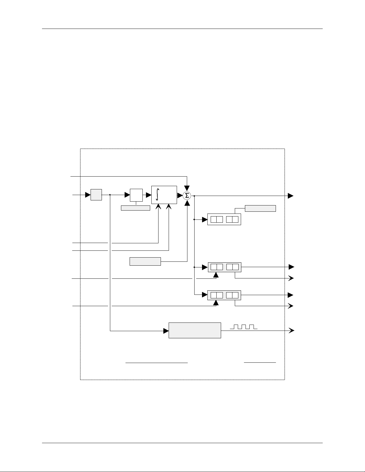
Function Blocks UM353-1
BLOCK DIAGRAM
Be sure that the PUL SCAL setting does not require a pulse rate output greater than the scan cycle time of the
controller under the maximum input conditions. Using the same example, if the maximum A input is 60.0 and the
cycle time is 0.1 sec, the maximum required pulse rate is 0.1/sec. The condition is satisfied since the maximum
output requirement is less than the maximum pulse rate of 5/sec available with a 0.1 sec cycle time. The
requirement would also be satisfied if a PUL SCAL of 1 was selected which would have required a maximum pulse
rate of 1/sec.
POWER UP - During a warm start, if the configuration parameter PU LAST was set to YES, the integrator
function will initialize with the last value prior to power down and all outputs will be initialized to the last value
prior to power down. If set to NO, or during a cold start, the integrator and all outputs will initialize to 0.
Input EC allows the batch totalizer block to be used with another function block, such as the DINU that provides a
count signal. When input A is not configured it will be set to (0.0). The EC input is summed with the initial value
for use as the total. This value will now be displayed as the total on the operator faceplate and the presets will act
on this value to provide outputs A1 and A2.
BATCH TOTALIZER
EC
.
T1
T2
S
R
External Count Input
1
ing ?
ital
VAL
Integrator
A(t)
ue
+
+
dt
+
alizer
Display (.T)
3
..
PRESET 1
7
..
2 1
0
TOT
0
_UNIT
Alarm 1
T
L
ota
TL
s
T
1
rip
T1
.
Z
ero Drop Out
A
ZDO
A
nalog Input
S
top
R
eset
+/
-
ect
DIR
ACT
INIT
T
rip 1 - External Setting
A1
T
rip 2 - External Setting
PRESET 2
8 0 0
..
A
T
larm
rip
2
T2
2
A2
se
SCAL
ing
PuL
se
PL
PUL
.00001 - 99999
3-30
October 2001
Required:
Max. Pulse Rate =
A (maximum)
[Time Base (sec) ][PUL SCAL]
Available:
Max. Pulse Rate =
0.5
Cycle Time
Page 61

UM353-1 Function Blocks
3.2.22 BATSW - Batch Switch
BATSW function blocks can be used on a one per loop
basis. Each is used with a PID function block to
eliminate overshoot during startup conditions. When
placed in the feedback path of the controller it causes the
reset component of the controller to be reduced (if
controller action is Rev). Without the use of a batch
switch during startup, the controller output (O1 = GE +
R) will equal full output since the reset will wind up. This
requires the process to overshoot the setpoint in order to
bring the controller output back down. With a batch
switch in the feedback path, a lower reset value will be
present when crossover occurs, thus reducing or
eliminating overshoot.
As input A equals or exceeds the HI or LO LIMIT setting, the output of the batch switch will be either decreased
(HI LIMIT) or increased (LO LIMIT), changing the feedback signal and therefore the controller reset signal. This
maintains controller output at the batch switch limit setting and eliminates reset windup.
If a controller has a large proportional gain setting, the reset can be modified too much, such that the process may
under shoot the setpoint during a startup condition. The BPL (Batch Pre-Load) is adjusted to optimize the
controller for startup conditions by limiting how much the batch switch can adjust the controller feedback signal.
When the controller output is within its normal operating output, the batch switch has no effect on the controller.
This allows the controller to be tuned optimally for normal operating conditions and the batch switch to add
additional compensation, very similar to derivative action, only during startup.
BATCH SWITCH
BATSW
A
Input
OL
I N U A
A
IH I
IML
L IMI T
PB L
IAG N
TP
E S N
T
ESN = 000
O1
(S)
gh
HI
LOw LIMIT
atch Pre-Load
B
GAIN
INPUT A
xec. Seq. No.
E
........................... Real (100.0)
LIMIT
(S)
........................... Real (0.0)
(S)
(S)
.................. Real (50.0)
.................................... Real (32.0)
(H)
loop tag.block tag.output (null)
....
(H)
........... 001 to 250
O
utput
1BATCH SWITCH
A
.
-
+
HI LIMIT
-
+
LO LIMIT
GAIN
GAIN
+
+
Batch Pre-Load
+
+
BLOCK DIAGRAM
HI
Selector
LO
Selector
LO
Selector
HI
Selector
Output
O1
.
October 2001
3-31
Page 62

Function Blocks UM353-1
3.2.23 BIAS - Bias
BIAS function blocks can be used on a one per loop basis
and provide a means to bias a signal, such as the setpoint in
an external set application. Inputs A and E (external bias)
are summed and then added to the operator adjustable bias
B.
Track Command input TC, asserted high (1), will cause the
block output to track input TV and BIAS to be recalculated
as B = TV - (A+E). The value of B will be clamped at the
HI and LO LIMIT settings. It is important to realize that
the inputs and outputs are in engineering units and the
limits must be adjusted accordingly with the expected
minimum and maximum required range values. The default
values have been set to -150.00 and +150.00, which might
be the normal expected limits when using the default range
of 0.0 to 100.0. These values can be set lower but have a
maximum setting of +/-150% of the range pointer value.
The default range is 0.00 to 100.00 if the pointer is not configured.
If, for example, the BIAS block is used to bias a flow setpoint with a range pointer (input R) of 0-6.00 GPM, the
maximum bias adjustments would be +/-9.00. If limit adjustments of +/-50% of this range are desired, then the
BIAS block LO LIMIT should be set at -3.00 and the HI LIMIT at +3.00. If a range change is made the current
LIMIT settings and the current BIAS value will be changed to be the same % value within the new range.
The BIAS can be adjusted using the QUICKSET feature if the parameter QUICKSET is set to YES. The BIAS
value will continuously change as the knob is adjusted but the STORE button must be pressed when the final value
is reached to insure that the new BIAS setting will be retained on a Cold power up condition.
Any unused inputs to the block will be set equal to 0.
The TO (Tracked Output) is normally used in applications where an external device is being used to set a bias in
place of the BIAS parameter (B is then set to 0.0). When it is desired to have the output of the BIAS block track
the TV variable, the external device is forced to track TO. Input E will then equal TV- [A+(0.0)] and, therefore,
the BIAS block output O1 will equal TV.
BIAS
R
Input
Input
T
rack Command
T
rack Variable
R G P T R
H
I
OL
I N U A
I
N
I
N
P
I
N
P
U I
Q
ange
LLI
P
U
U
C
A
E
B
I
U
T
T
K
R
A
E
TC
TV
AI
M I T
TP
T
T
T
ES T
E S
BIAS
O = B + A + E
RanGe P
BIAS
S
HI
LO
TIM
INPUT A
INPUT E
E
INPUT TC
C
INPUT TV
V
QUICK SET
xec. Seq. No.
E
N
000
ESN =
B
BIAS
oinTeR
..................................... Real (0.00)
(S)
gh Bias
LIMIT
w Bias
LIMIT
(H)
(H)
(H)
(H)
O1
TO
...
(S)
loop tag.block tag (null)
.................... Real (150.0)
(S)
(S) .................... Real (-150.0)
......
loop tag.block tag.output (null)
......
loop tag.block tag.output (null)
...
loop tag.block tag.output (null)
.... loop tag.block tag.output (null)
bias (S) ............. NO/YES (YES)
............ 001 to 250
(H)
O
1
utput
T
racked Output
A
+
A + E
+
+
E
A + E + B
+
+
+
Output 1
O1
-
TV - (A + E)
+
TC
.
TV
3-32
October 2001
Track Command
Track Variable
B
TC
BLOCK DIAGRAM
TV - (A + B)
-
TO
Tracked
+
Output
.
Page 63

UM353-1 Function Blocks
3.2.24 CIE_- Coil Inputs - Ethernet (V2.4)
CIE_ function blocks are available when the optional
Ethernet communication board is installed. They allow the
controller to obtain up to 16 discrete Modbus coil data from
other stations over Ethernet. A configuration value of 0000
will turn off the channel. The configuration includes the IP
address of the other device on the Ethernet network, the
number of coils requested, and the starting coil address.
Up to 32 CIE_ blocks are available and are assigned in
sequence with each use, station wide. The data are received
as boolean values that are dispersed to individual boolean
outputs. C0 gets the value of the first start-coil and each
subsequent output gets the next value. If there are less than
16 coils, the remaining values will be set to zero.
3.2.25 CHR_ - Characterizer
CHR_ function blocks provide 10 segments that can be
used to characterize the X input signal. Individual
segments are configured by entering the Xn, Yn and
Xn+1, Yn+1 points for each segment. All Xn+1 points
must be greater than the associated Xn points. Input X is
in engineering units and the Y points should be in the
engineering units desired for the characterizer output.
CHARACTERIZER
Y5
Y6
Y4
Y7
Y8
Y3
Y2
Y9
Y10
Y1
Y0
Output Coordinates
X
Input X
0
X
X1
X2 X3
BLOCK DIAGRAM
X4
X5X6X7X8X9
Input Coordinates
Output Y
10
X
X03131S0
OY
CHARACTERIZER
Input
X
X
X
0
1
X
2
X
3
X
X
4
5
X
6
X
7
X
8
X
9
X
X 1 0
0
Y
1
Y
2
Y
3
Y
Y
4
5
Y
6
Y
7
Y
Y
8
9
Y
0
Y 1
I N P U T X
SEN
CHR_ ESN = 000
CHARACTERIZER
Input Coordinate X0
Input Coordinate X1
Input Coordinate
Input Coordinate
Input Coordinate X4
Input Coordinate X5
Input Coordinate X6
Input Coordinate X7
Input Coordinate
Input Coordinate X9
Input Coordinate
Output Coordinate Y0
Output Coordinate Y1
Output Coordinate Y2
Output Coordinate Y3
Output Coordinate Y4
Output Coordinate Y5
Output Coordinate Y6
Output Coordinate Y7
Output Coordinate Y8
Output Coordinate
Output Coordinate
INPUT X
xec. Seq. No.
E
X2
X3
X8
X10
(H)
..................
(H)
.......................... 001 to 250
utput
O
OY
(S)
............................ Real (0.0)
(S)
............................ Real (10.0)
(S)
............................ Real (20.0)
(S)
............................ Real
(S)
............................ Real (40.0)
(S)
............................ Real (50.0)
(S)
............................ Real (60.0)
(S)
............................ Real
(S)
............................ Real (80.0)
(S)
............................ Real (90.0)
(S)
.......................... Real . (100.0)
(S)
......................... Real
(S)
......................... Real (10.0)
(S)
......................... Real (20.0)
(S)
......................... Real
(S)
......................... Real (40.0)
(S)
......................... Real (50.0)
(S)
......................... Real (60.0)
(S)
......................... Real
(S)
......................... Real (80.0)
(S)
......................... Real (90.0)
Y9
(S)
....................... Real (100.0)
Y10
oop tag.block tag.output (null)
l
Y
(30.0)
(70.0)
(0.0)
(30.0)
(70.0)
October 2001
3-33
Page 64

Function Blocks UM353-1
BLOCK DIAGRAM
3.2.26 CMP_ - Comparator
CMP_ function blocks compare analog input A with an
external or internal limit setting and provide a high (1)
output when the limit is exceeded.
ACTION - the CMP block can be configured as direct or
reverse action. Direct action will cause the output to go
high when input A is equal to or greater than the limit.
Reverse action will cause the output to go high when
input A is equal to or less than the limit.
DIRect ACTing
EL
A
Analog
Input
External
Limit
LIMIT
BLOCK DIAGRAM
+
O1
Output 1
-
X03132S0
DEAD BAND - the output will return from a high (1) output to a low (0) output when input A is less than the limit
- Dead BAND setting for direct action or greater than the limit + Dead BAND for reverse action.
EXTERNAL LIMIT - When input EL is configured, the LIMIT setting will be ignored and the value of input EL
will be used as the limit value.
COMPARATOR
A
nalog Input
L
DRB A
I
ELE
I
N D
C
A
TU
E
E S N E
xternal Limit
D
N P U T
I
NI
P
A
T
IM
T
A
L
ESN = 000
CMP_
COMPARATOR
Comparator
D
DIR
INPUT A
INPUT EL
LIMIT
ead
BAND
ect
ing
ACT
(H)
..........
(H)
xec. Seq. No.
(S)
........
O
1
utput
O1
(S)
..................... Real (0.0)
.............................. Real (0.5)
(S)
.................... NO/YES (YES)
loop tag.block tag.output (null
loop tag.block tag.output (null)
(H)
................ 001 to 250
)
3.2.27 COS_ - COSINE
COS_ function blocks, in firmware 1.30 and higher, accept radian
inputs and output the cosine of that angle.
.
Input
X
COS (X)
O
utput
O1X
1
.
COSINE
COS
Input
X
X
O1 = COS (X)
XTUPNI INPUT X ..............
E Exec. Seq. No. ..................... 000 to 250 (000)
S N
000
ESN =
loop tag.block tag.output (null
utput
O
O1
1
)
3-34
October 2001
Page 65

UM353-1 Function Blocks
BLOCK DIAGRAM
3.2.28 DAM_ - Deviation Amplifier
DAM_ function blocks compute the difference between
inputs A and B, amplify the difference signal, and sum
the resultant with an internal BIAS and an external signal
at input C. Unused inputs are set to 0.0.
BIAS
A
Input
A
+
GAIN
-
B
Input
B
C
.
Input
C
O1 = GAIN x (A - B) + BIAS + C
+
+
utput
+
O
O1
1
DEVIATION AMPLIFIER
A
Input
Input
Input
.
I N U ATP
I
I N U
N
B
C
BAI S
UBTP
P
A
B
C
A
T
E S N
NG
I
C
ESN = 000
DAM_
DEVIATION
AMPLIFIER
(S)
.................................... Real (1.0)
GAIN
(S)
..................................... Real (0.0)
BIAS
(H)
loop tag.block tag.output (null)
INPUT A
INPUT B
INPUT C
E
.....
(H)
.....
(H)
.....
xec. Seq. No.
loop tag.block tag.output (null)
loop tag.block tag.output (null)
(H)
............ 001 to 250
O1`
O
utput
1
October 2001
3-35
Page 66

Function Blocks UM353-1
BLOCK DIAGRAM
3.2.29 DID_ - Digital Input lev_Discrete
DID_ function blocks convert 16 on/off signals received from
a single or multiple nodes on the LonWorks network into 16
block outputs for use by other function blocks within the
controller. A maximum of 6 DID blocks can be used, up to
the limit of nodes allowed on the Lon network or the memory
limit of the controller. Each use of the block will be assigned
a unique station wide ID (e.g. DID02). Input connections are
established by ‘binding’ each output variable of type
SNVT_lev_disc (SNVT #22) in the remote node devices to
each network variable in the DID function block. These
blocks will be available when the LonWorks option board is
installed in a 352P, 353, or 354N controller.
The 0 NV NUM parameter enables the number that the
station has assigned to input 0. All subsequent network
variables are assigned consecutively.
Each function block output has a mode associated with it.
The mode can be either NORMAL or FORCED. When using
a PC capable of sending LIL or Modbus commands, the mode
can be changed and the forced state can be assigned a high
(1) or low (0) value. The values accessible over the network
are the two switch inputs (N and F) and the position of the
SPDT switch illustrated in the block diagram. A mode of ‘0’
is Normal and ‘1’ is Forced.
Each function block output also has a quality status associated
with it. This status will go high (1) when the block
determines it has lost communication with the Lon node. If
any of the individual quality outputs are high the Quality Status block output will also be high.
DIGITAL INPUT LEV_DISCRETE
0
LonWorks
Remote I/O Bus
nviDIDnn_0
nv*
SNVT _ lev_disc
0
nviDIDnn_1
nv*
SNVT _ lev_disc
1
nviDIDnn_2
nv*
SNVT _ lev_disc
2
nviDIDnn_3
nv*
SNVT _ lev_disc
3
nviDIDnn_4
nv*
SNVT _ lev_disc
4
nviDIDnn_5
nv*
SNVT _ lev_disc
5
nviDIDnn_6
nv*
SNVT _ lev_disc
6
nviDIDnn_7
nv*
SNVT _ lev_disc
7
nviDIDnn_8
nv*
SNVT _ lev_disc
8
nviDIDnn_9
nv*
SNVT _ lev_disc
9
nviDIDnn_A
nv*
SNVT _ lev_disc
A
nviDIDnn_B
nv*
SNVT _ lev_disc
B
nviDIDnn_C
nv*
SNVT _ lev_disc
C
nviDIDnn_D
nv*
SNVT _ lev_disc
D
nvDIDnn_E
nv*
SNVT _ lev_disc
E
nviDIDnn_F
nv*
SNVT _ lev_disc
F
N
V
N U M
DID_
DIGITAL INPUT
LEV_DISCRETE
(16 channel)
(Channel 0)
(Channel F)
etwork
ariable
0 N
V
NUM
O
utput 0
O0
Q
uality 0
Q0
O
utput F
OF
Q
uality F
QF
Q
uality Status
QS
ber (nv *) (R) ....... 1 to 2000 (*)
LonWorks Remote Devices
Station
node r1
nv x1
SNVT_
nv x1 binding
node r2
nv x1
SNVT_
nv x1 binding
node u, nv *E
node u, nv *0
nv x2 SNVT_
nv x2 binding
node u, nv *1
Remote
I/O Bus
nv x2 SNVT_
nv x2 binding
node u, nv *F
X03133S0
3-36
October 2001
LonWorks
option board
node u
nv*0
SNVT_
Channel 0
nv *0
SNVT_
Channel F
Quality Test
N
O0
F
0
F
Q0
N
OF
F
F
F
QF
QS
Page 67

UM353-1 Function Blocks
3.2.30 DIE_ - Digital Input - Ethernet (V2.4)
DIE_ function blocks are available when the optional
Ethernet communication board is installed. They allow the
controller to obtain up to 16 digital points from another
Moore or Procidia controller over the Ethernet network.
Up to 32 DIE_ blocks are available and they are assigned
in sequence with each use, station wide. The data is
received as an integer value and is fanned out to the block
outputs D0 - DF
Output QS indicates the quality of the received data and
will go high (1) when the data is bad. This is normally
associated with failure to receive data due to a
communication failure or a misconfiguration of the source.
Modbus registers associated with DOE function blocks for
digital inputs coming from other controllers are listed below.
FB Number MB
Register
FB Number MB
Register
DOE01 31025 DOE09 31033 DOE17 31041 DOE25 31049
DOE02 31026 DOE10 31034 DOE18 31042 DOE26 31050
DOE03 31027 DOE11 31035 DOE19 31043 DOE27 31051
DOE04 31028 DOE12 31036 DOE20 31044 DOE28 31052
DOE05 31029 DOE13 31037 DOE21 31045 DOE29 31053
DOE06 31030 DOE14 31038 DOE22 31046 DOE30 31054
DOE07 31031 DOE15 31039 DOE23 31047 DOE31 31055
DOE08 31032 DOE16 31040 DOE24 31048 DOE32 31056
DIGITAL INPUTS 16 CHAN - ETHERNET
DIE_
DIGITAL INPUTS
16-CHAN ETHERNET
Ethernet Network
P A R E S
I D
M B E GR
FB Number MB
Register
IP ADdRES
ModB
D0
DF
QS
nnn.nnn.nnn.nnn (192.168.0.0)
(H)
s
.
REG
us
ister (H) .. 0000 - 65535
FB Number MB
Output D0
Output DF
Output QS
(0)
(Rev. 2)
Register
3.2.31 DIL_ - Discrete Input _ LIL
DIL_ function blocks are available when the optional LIL
communication board is installed. DIL block numbers are
assigned in sequence with each use, station wide. The block
allows the station to obtain a global word (GW) from another
station on the LIL.
The function block has 16 outputs, D0 through DF, which
represent the values of bits 0-F in the global word. Output QS
indicates the quality of the received data and will go high (1)
when the data is bad. This is normally associated with failure to
receive global data due to a LIL failure or a misconfiguration of
the source.
The received global word will also be re-transmitted by this station as a parameter 1 value in the configured
channel n.
1 2 3 4 5 6 7 8 9 10` 11 12
n GW SA/SC
DISCRETE (WORD) INPUT - LIL
DIL_
DISCRETE (WORD)
LIL
GLOBAL
S R C E A D D
S R C E C H N
INPUT - LIL
DATA
C ALIL
H
N
D0
DF
QS
SouRCE ADD
SouRCE CHaN
LIL CHAN
ress (H) ...... 00 to 64 (null)
nel (H) .. 000 to 255 (null)
nel (H) .......... 008 to 255 (null)
Output
Output
Output
D0
DF
QS
October 2001
3-37
Page 68

Function Blocks UM353-1
BLOCK DIAGRAM
3.2.32 DIN_ - Digital Inputs
DIN_ function blocks can be used to sense a discrete
signal from an external source and provide a block output
representing the state of this signal. Blocks are available
on the Controller Board and on the Expander Board.
Function block names (IDs) and terminal designators are
listed in Section 8.4.
The block output is high (1) when the input is on and low
(0) when off.
Output QS indicates the quality status of the output signal
O1 and will be high (1) when the output is of bad quality.
Bad quality indicates any hardware failure of the input
converter.
DIN_+
24 Vdc
+
-
DIN_-
A/D
O1
DIGITAL INPUT _
DIN_+
DIN_-
DIN_
DIGITAL INPUT
O1
QS
Output 1
Quality Status
Typical External
Circuit
Quality Test
QS
3-38
October 2001
Page 69

UM353-1 Function Blocks
.
3.2.33 DINU_- Digital Inputs, Universal
DINU_ blocks have multi-function capability:
• sensing a discrete input and providing a high (1) or
low (0) output representing the state of the input
• totalizing and scaling the count of input pulses
• converting the rate of input pulses to a scaled analog
frequency output
Two DINU_ blocks are available on the I/O expander
board. The fixed names (IDs) of these blocks and their
terminal designations are listed in Section 8.4.
Output CT represents the scaled (actual count x K) total of
input pulses that occurred since the last reset. This output
is a real number and can be used in a number of
applications, such as a direct count input to the BAT batch
totalizer function block or in math operations, such as
computing the difference between counts in a ratio trim
circuit.
Output IS is the current state of the input at the time the
block is executed at the start of each controller scan cycle.
It will be low (0) when the input is low and high (1) when the input is high.
Output SF is a scaled frequency (using the FREQ MIN and MAX parameters) that can represent flow rate, speed,
or other transmitter variable that has a frequency signal. When the FREQ MAX parameter is set to 25 or less, a 20
msec contact debounce is used. When contact debounce is used, a pulse input must remain on for 20 msec to be
recognized as a valid pulse. Output SF is linear with frequency and can be characterized using the CHR function
block if necessary. An engineering range and units are assigned to this signal using the MINSCALE,
MAXSCALE, DPP, and ENGUNITS parameters. They are available to other blocks using the OR output
connection.
Input R resets output CT to 0.0. Input D controls the direction of the count. When direction input D is low (0),
the count will move backwards, including negative values. The direction input feature enables the use of count
down counters and it allows duplication of functions performed by previous computer pulse interfaces having a
Pulse/Direction format. Input TC asserted high (1) will force the scaled count to track an external signal. This
can be used in applications where the CT output is being used to set a value (e.g. setpoint) that can be changed
from another source.
The quality status output QS indicates the
quality of the block outputs and is high (1)
when outputs CT, IS, or SF are of bad
TV
TC
Reset
R
Direction
D
Track Variable
Track Command
quality. Bad quality indicates a failure in the
hardware conversion circuit.
DIU_+
.
Current Limit < 7 mA
POWER UP - With PU LAST set to YES, the
CT output will power up at the last value
DIU_-
during a hot or warm start. If set to NO,
during a warm or a cold start it will be set to
0.0. The digital filter will be temporarily bypassed during a hot, a warm or a cold start.
DIGITAL INPUT - UNIVERSAL
DINU_
eset
R
R
irection
D
rack Variable
T
rack Command
T
DINU_+
DINU_-
E
Q
EFR Q
N
S
U N I T SGNE
P U T
Z D O
M
M
A
C
CS
D P P
L A S T
T
R
F
D I G F I L T
IM
A XM
P U
I N P U T
IINNPPUUT
DIGITAL INPUT
D
UNIVERSAL
TV
TC
ero Drop Out frequency (H) ................. Real
Z
uency
N FREQ
I
A X
FREQ
K
ELACSK
DIG
MIN
EL
MAX
ELA
D
ENG
P
INPUT R
R
INPUT D
D
T
V
INPUT TV
CTI N
INPUT TC
P/A Converter
BLOCK DIAGRAM
MIN
uency
MAX
factor
SCALE
ital
er
FILT
imum
SCALE
imum
SCALE
ecimal Point Position (preferred)
ineering
ower Up
LAST
(H)
..................
(H)
..................
(H) ................
(H) ................
Count
K
Digital
Filter
utput Range
O
OR
ount Total
C
CT
caled Freq.
S
SF
nput State
I
IS
uality Status
Q
QS
imum Hz (H) ................ Real
imum Hz (H) ............... Real
(H)
................................ Real
(S)
....................... 0 to 180 sec
(H) ............................. Real
(H) ............................ Real
(S)
............. 0.0.0.0.0.0 (0.00)
(S) ............ 6 Char ASCII (PRCT)
UNITS
(S) .......................... NO/YES
loop tag.block tag.output
loop tag.block tag.output (null)
loop tag.block tag.output (null)
loop tag.block tag.output
Count Total
ENG UNITS
Scaled Freq.
Scaling
Quality Test
(0)
(0)
(1000)
(1.0)
(0 sec)
(0.0)
(100.0)
(YES)
(null)
(null)
CT
SF
IS
QS
October 2001
3-39
Page 70

Function Blocks UM353-1
BLOCK DIAGRAM
3.2.34 DIS_ - Digital Input _ State
DIS_ function blocks, in firmware 1.30 and higher, convert a 16bit word received from a single node on the LonWorks network
into 16 block outputs for interconnection to other function blocks
within the controller. A maximum of 6 DIS blocks can be used,
up to the limit of nodes allowed on the Lon network or the
memory limit of the controller. Each use of the block will be
assigned a unique station wide ID (e.g. DIS02). Input connections
are established by ‘binding’ the output variable of type
SNVT_state (SNVT #83) in the remote node to the network
variable in the DIS function block. These blocks will be available
when the LonWorks option board is installed in a 352P, 353, or
354N controller.
The 0 NV NUM parameter enables viewing the number that the
station has assigned to input 0.
Each function block output has a mode associated with it. The
mode can be either NORMAL or FORCED. When using a PC
capable of sending LIL or Modbus commands, the mode can be
changed and the forced state can be assigned a high (1) or low (0)
value. The values accessible over the network are the two switch
inputs (N and F) and the position of the SPDT switch illustrated
in the block diagram. A mode of ‘0’ is Normal and ‘1’ is Forced.
The function block also has a quality status output associated with
it. This status will go high (1) when the block determines it has lost communication with the Lon node.
Station
LON
option board
node u
DIGITAL INPUT _ STATE
LONWorks
Network
nviDSnn0
nv*
SNVT _ state
0
V
N N U M
DISnn
DIGITAL INPUT
STATE
view Network
ariable
V
O0
O1
O2
O3
O4
O5
O6
O7
O8
O9
OA
OB
OC
OD
OE
OF
QS
ber (nv *) .... 1 to 2000 (*)
NUM
utput 0
O
utput 1
O
utput 2
O
utput 3
O
utput 4
O
utput 5
O
utput 6
O
utput 7
O
utput 8
O
utput 9
O
utput A
O
utput B
O
utput C
O
utput D
O
utput E
O
utput F
O
uality Status
Q
LON node r1
nv x1 SNVT_
nv x1 binding
node u, nv *0
LON network
nv _ SNVT_
N
F0
F
N
FF
F
Quality Test
QS
O0
OF
.
.
3-40
October 2001
Page 71

UM353-1 Function Blocks
BLOCK DIAGRAM
3.2.35 DIV_ - Division
DIV_ function blocks perform simple arithmetic division.
The output will be the quotient of the two configured
inputs N/D. The output will be limited to the maximum
real number and, if the divisor is 0.0, the output will go to
the maximum real number with the sign determined by
the numerator. If the numerator is 0.0, the output will be
0.0.
Any unconfigured inputs will be set equal to 1.0.
N
N
umerator
DIVISION
N
umerator
D
enominator
NI
PNI
DIV_
N
DIVISION
D
UP
INPUT N
NT
INPUT D
D
TU
E
S N
xec. Seq. No.
E
000
ESN =
O
utput
O1
(H)
.......... loop tag.block tag.output (null)
..........
(H)
loop tag.block tag.output (null)
................ 001 to 250
(H)
1
O
01 = N/D
.
D
D
enominator
BLOCK DIAGRAM
utput
O1
1
3.2.36 DNC_ - Divide by N Counter
DNC_ function blocks provide a single output pulse for a
pre-selected number of input pulses. The output will go
high (1) with a positive transition of the input P, edge
triggered, and will return to a low (0) output on the
succeeding positive transition.
N
3
R
Reset
.
P
2
Output 1
Divide By 3
Output 1
Divide By 2
Pulse Input
O1
.
POWER UP - During a hot or a warm start, with PU LAST
set to YES, the block will retain the last count and continue
at the last input/output states. If set to NO, during a warm or
a cold start, the output and count will be initialized to 0.
.
DIVIDE BY N COUNTER
000
O1
(S)
................... NO/YES (YES)
LAST
(H) ...........
loop tag.block tag.output (null)
(H) ...........
loop tag.block tag.output (null)
(H)
................. 001 to 250
O
utput
1
ulse Input
P
eset
R
U L A S T
P
I
DNC_ ESN =
P
DIVIDE BY N
COUNTER
R
Counter Divisor N (S) ............. 2 - 999999 (2)
N
ower Up
P
INPUT P
TUPN
P
INPUT R
RTUPNI
xec. Seq. No.
E
E S N
October 2001
3-41
Page 72

Function Blocks UM353-1
BLOCK DIAGRAM
LonWorks remote
3.2.37 DOD_ - Digital Output lev_Discrete
DOD_ function blocks transmit up to 16 on/off signals
received from a controller block interconnection to
remote nodes on the LonWorks network. A maximum of
6 DOD blocks can be used, up to the limit of nodes
allowed on the Lon network or the memory limit of the
controller. Each use of the block will be assigned a
unique station wide ID (e.g. DOD01). Each input
transmitted is of type SNVT_lev_disc and can be bound
to network variables in a single or multiple remote nodes
that can receive network variables of this type. These
blocks will be available when the LonWorks option board
is installed in a 352P, 353, or 354N controller. The 0 NV
NUM parameter enables the number that the station has
assigned to input 0 to be viewed. All subsequent network
variables are assigned consecutively.
Each function block input has a mode associated with it.
The mode can be either NORMAL or FORCED. When
using a PC capable of sending LIL or Modbus
commands, the mode can be changed and the forced state
can be assigned a high (1) or low (0) value. The values
accessible over the network are the two inputs (F and N)
and the position of the SPDT switch illustrated in the
block diagram. A mode of ‘0’ is Normal and ‘1’ is
Forced.
Station
I/O devices
LonWorks
option board
F
0
F
N
F
1
F
N
SNVT_
nv *0
nv *0 binding
node r1, nv z1
nv *1
SNVT_
nv *1 binding
node r1, nv z2
......
F
node u
FE
E
N
F
FF
F
N
SNVT_
nv *E
nv *E binding
node r6, nv z1
SNVT_
nv *F
nv *F binding
node r6, nv z2
Remote
I/O Bus
node r1
nv z1
SNVT_
......
nv z2
SNVT_
node r2
SNVT_
nv z1
......
nv z2
SNVT_
......
node r6
SNVT_nv z1
......
nv z2
SNVT_
X03139S0
Each function block input also has a quality status associated
with it. This status will go high (1) when the block
determines it has lost communication with the Lon node
bound to that input. If any of the individual quality inputs are
high, the Quality Status block output will also be high.
DIGITAL OUTPUT LEV_DISCRETE
DOD_
DIGITAL OUTPUT
LEV_DISCRETE
(16 channel)
Input 0
0
F
Q0
QF
QS
(Channel 0)
(Channel F)
U
N M
etwork
0 N
INPUT 0
INPUT F
V
(S)
(S)
ariable
............
............
Quality 0
Input F
Quality F
Quality Status
0
I N
...........
I N
V
N
P U T 0
PUT F
LonWorks
Network
nvoDODnn_0
nv*0
SNVT _lev_disc
nvoDODnn_1
nv*1
SNVT _ lev_disc
nvoDODnn_2
nv*2
SNVT _ lev_disc
nvoDODnn_3
nv*3
SNVT _lev_disc
nvoDODnn_4
nv*4
SNVT _ lev_disc
nvoDODnn_5
nv*5
SNVT _ lev_disc
nvoDODnn_6
nv*6
SNVT _ lev_disc
nvoDODnn_7
nv*7
SNVT _ lev_disc
nvoDODnn_8
nv*8
SNVT _ lev_disc
nvoDODnn_9
nv*9
SNVT _ lev_disc
nvoDODnn_A
nv*A
SNVT _ lev_disc
nvoDODnn_B
nv*B
SNVT _ lev_disc
nvoDODnn_C
nv*C
SNVT _ lev_disc
nvoDODnnD
nv*D
SNVT _ lev_disc
nvoDODnn_E
nv*E
SNVT _ lev_disc
nvoDODnn_F
nv*F
SNVT _ lev_disc
ber (nv*)
(R)
NUM
loop tag.block tag.output (null)
loop tag.block tag.output (null)
.... 1 to 2000
(*)
3-42
October 2001
Page 73

UM353-1 Function Blocks
3.2.38 DOE_ - Digital Output - Ethernet (V2.4)
DOE_ function blocks are available when the optional
Ethernet communication board is installed. Up to 32 DOE
blocks are available and are assigned in sequence with each
use, station wide.
Up to 16 digital inputs can be configured. The block will
pack inputs I0 - IF into a single integer word which can be
accessed from another controller having Ethernet
communication capability.
Each DOE block is automatically assigned Modbus
registers that can be accessed from any device having the
Modbus Ethernet capability.
DIGITAL OUTPUT - ETHERNET
DOE_
Input 0
Input F
I N P U T 0 INPUT
I N P U T 1
I N P U T 2
I N
P U T
I N
P U T
I N
P U T
I N
P U T
I N
P U T
I N
P U T
I N
P U T
I
N P U T
I N P U T
I N P U T
I N P U T
I N P U T
I N P U T
I0
DIGITAL OUTPUT
IF
3
4
5
6
7
8
9
A
B
C
D
E
F
ETHERNET
0 (H) ............... loop tag.block tag.output
(H) ............... loop tag.block tag.output
INPUT 1
(H) ............... loop tag.block tag.output
INPUT 2
(H) ............... loop tag.block tag.output
INPUT 3
(H) ............... loop tag.block tag.output
INPUT 4
(H)
............... loop tag.block tag.output
INPUT 5
(H)
............... loop tag.block tag.output
INPUT 6
(H)
............... loop tag.block tag.output
INPUT 7
(H)
............... loop tag.block tag.output
INPUT 8
(H) ............... loop tag.block tag.output
INPUT 9
(H) ............... loop tag.block tag.output
INPUT A
(H) ............... loop tag.block tag.output
INPUT B
(H) ............... loop tag.block tag.output
INPUT C
(H) ............... loop tag.block tag.output
INPUT D
(H) ............... loop tag.block tag.output
INPUT E
(H) ............... loop tag.block tag.output
INPUT F
Ethernet Network
(null)
(null)
(null)
(null)
(null)
(null)
(null)
(null)
(null)
(null)
(null)
(null)
(null)
(null)
(null)
(null)
(Rev. 2)
3.2.39 DOL_ - Discrete Output - LIL
DOL_ function blocks are available when the optional LIL
communication board is installed. They allow the station to
output a global word GW with bits 0-F representing the
state 1 or 0 of each of the Boolean inputs D0 - DF.
Unconfigured inputs are set to 0. DOL block numbers are
assigned in sequence with each use, station wide.
1 2 3 4 5 6 7 8 9 10` 11 12
n GW
DISCRETE (WORD) OUTPUT - LIL
DOL
D0
Input
D0
DISCRETE (WORD)
N
F
OUTPUT - LIL
(H)
nel
LIL CHAN
INPUT DO
INPUT DF
.........................
(S)
..... loop tag.block tag.output
(S) ...... loop tag.block tag.output (null)
DF
Input
I
L
INP UTD 0
I
C AL
H
N P U T D
DF
008 to 255 (null)
LIL
GLOBAL
DATA
(null)
October 2001
3-43
Page 74

Function Blocks UM353-1
BLOCK DIAGRAM
3.2.40 DOS__ - Digital Output State
DOS_ function blocks, in firmware 1.30 and higher, transmit up
to 16 on/off signals received from a controller block
interconnection to a remote node on the LonWorks network as a
single 16-bit word value. A maximum of 6 DOS blocks can be
used, up to the limit of nodes allowed on the Lon network or the
memory limit of the controller. Each use of the block will be
assigned a unique station wide ID (e.g. DOS01). The transmitted
value is of type SNVT_state and can be bound to a network
variable in a remote node that can receive a network variable of
this type. These blocks will be available when the LonWorks
option board is installed in a 352P, 353, or 354N controller.
Each function block input has a mode associated with it. The
mode can be either NORMAL or FORCED. When using a PC
capable of sending LIL or Modbus commands, the mode can be
changed and the forced state can be assigned a high (1) or low (0)
value. The values accessible over the network are the two switch
inputs (N and F) and the position of the SPDT switch illustrated
in the block diagram. A mode of ‘0’ is Normal and ‘1’ is Forced.
The function block also has a quality status associated with it.
This status will go high (1) when the block determines it has lost
output communication with the Lon node bound to that input.
Station
DIGITAL OUTPUT _ STATE
0
1
2
3
4
5
6
7
8
9
A
B
C
D
E
F
QS
DOSnn
DIGITAL OUTPUT
STATE
view Network Variable
UN V N M
INPUT 0 ............... loop tag.block tag.output (null)
INPUT F ............... loop tag.block tag.output (null)
Input 0
Input 1
Input 2
Input 3
Input 4
Input 5
Input 6
Input 7
Input 8
Input 9
Input A
Input B
Input C
Input D
Input E
Input F
Quality Status
I N P U T 0
...........
I N P U T F
LONWorks
Network
nvoDODnn0
nv*0
SNVT _lev_disc
ber (nv*) .. 1 to 2000
NUM
(*)
QS
LON
option board
F
0
F
N
0
F
F1
N
1
F
FE
N
E
F
F
F
N
F
node u
SNVT_nv _
nv_ binding
node r1, nv z1
LON network
LON node r1
nv z1
SNVT_
3-44
October 2001
Page 75

UM353-1 Function Blocks
BLOCK DIAGRAM
3.2.41 DOUT_ - Digital Outputs
DOUT_ function blocks are used to turn on remote
devices powered from an external source. The negative
terminal of the external power source must be connected
to station common. The transistor switch will turn on
when the block input S is high (1) and will turn off when
low (0). Two digital output function blocks are available
on the Controller Board.
DIGITAL OUTPUT _
DOUT_
Switch
DIGITAL OUTPUT
S
Open Collector
Transistor Switch
DOUT_+
DOUT_c
DOUT_+
S
D/A
DOUT_c
RELAY
24 V dc
Typical External
Relay Circuit
(H)
I
NPU
T S
INPUT S
loop tag.block tag.output (null)
......
Terminal Connections:
DOUT1 ----- DOUT1+ (8) -- DOUT1c (9)
DOUT2 ----- DOUT2+ (10) -- DOUT2c (9)
October 2001
3-45
Page 76

Function Blocks UM353-1
BLOCK DIAGRAM
3.2.42 DTM_ - Dead Time Table
DTM_ function blocks provide shift registers to hold the
analog input signal A for a period of time and shift it from
register to register to provide an overall delay between
input and output as configured in parameter DEADTIME.
Input AT can be used to adapt the DEADTIME to an
external signal. The actual shift register used as the block
output will equal the whole value of input AT (e.g. 0.184
= register 0, 1.897 = register 1).
Output MA will provide the moving average of register 0
to the output register divided by the number of registers
[e.g. output register = 50, MA = (R0+R1+R2+......+R50)/51].
Input E asserted high (1) will enable the operation of the DTM block. When this input is not configured, it will be
set high. A low (0) input will cause all registers and the outputs to equal the input A.
POWER UP - During a warm or cold start, all outputs will be initialized at 0 and all registers will be initialized to
the value of the input on the first scan.
DEAD TIME
A
nalog Input
E
A
daptive Time
D E
I
I
I N U TTP
nable
A
N
N
ESN =
DTM_
A
DEAD TIME
E
AT
DEAD TIME
T
UATP
U
I M
T
A
E S N
E
E
INPUT A
INPUT E
INPUT AT
xec. Seq. No.
E
D
P
000
O1
MA
........ 0.0 to 10000 min. (0.0)
(S)
(H)
.......
loop tag.block tag.output (null)
(H)
.......
loop tag.block tag.output (null)
.....
(H)
loop tag.block tag.output (null)
.............. 001 to 250
(H)
O
1
utput
M
oving Average
Enable
E
n-1
n-2
n-48
n-49
n-50
n
.
.
.
.
Register 0
Register 1
SHIFT REGISTERS
Register 50
.
.
.
.
.
.
.
.
.
.
.
.
Moving Average
Output 1
O1
MA
.
A
AT
Analog Input
Adaptive Time
3-46
October 2001
Page 77

UM353-1 Function Blocks
3.2.43 DYT_ - Delay Timer
DYT_ function blocks perform either an ON or OFF
output delay as determined by the TYPE configuration
parameter.
ON Delay - When input P is low (0), output O1 is low.
If P goes high (1), the elapsed timer starts and sets O1
high upon reaching the DLY TIME, provided P is still
high.
OFF Delay - When input P is high (1) the output is
high. If P goes low (0), the elapsed timer starts and
sets O1 low upon reaching the DLY TIME, provided P
is still low.
In firmware 1.30 and higher, the DLY TIME is adjustable over the full range of the display, which is 0.00000 to
999999. In earlier versions, the minimum time setting is 0.1. If the delay time is set to less than the scan time of
the station, the delay time will equal the scan time.
Output ET (elapsed time) will ramp from 0.0 to the value of DLY TIME and remain there until P resets the output.
Output RT (remaining time) equals DLY TIME - ET.
POWER UP - During a warm or a hot start, with PU LAST set to YES, the block will initialize with the
input/output states and elapsed time in effect at the instant power down occurred. A cold start, with PU LAST set
to NO, will initialize the input/output states and elapsed time to 0.
DELAY TIMER
P
ulse Input
L Y
D T
T Y E
U
N
P
I
P
P
A
TU
E S N
DYT_
DELAY TIMER
DeLaY TIME
EMI
Timer TYPE
ower Up
P
TP L S
INPUT P
P
xec. Seq. No.
E
000
ESN =
ET
RT
O1
(S)
LAST
(H)
..........
(minutes)
(S)
.............. Real (0.0)
........................ OFF/ON (OFF)
(S)
.................. NO/YES (YES)
loop tag.block tag.output (null)
(H)
................ 001 to 250
E
lapsed Time
R
emaining Time
O
1
utput
OFF
DLY TIME
ON
DLY TIME
P
.
1
O1
0
ET
0.0
1
O1
0
ET
0.0
1
0
ET
RT
O1
.
October 2001
3-47
Page 78

Function Blocks UM353-1
BLOCK DIAGRAM
3.2.44 E/I - External/Internal Transfer Switch
E/I function blocks can be used on a one per loop
basis to select an analog signal, connected to input E
(External) or input I (Internal), as a setpoint for the
loop controller.
The position of the E/I switch can be changed on each
positive transition of input ST and will normally be
connected to the PS output of pushbutton block
PB2SW, configured for momentary action. The SE
output will normally be connected to the MD input of
pushbutton block PB2SW. E/I switch position will be
shown on the operator faceplate by a lighted LED:
green for E, red for I.
The E/I switch position can also be changed by
command over the Modbus or LIL network.
When PU LAST is set to YES, the E/I switch will
power up in the last position during a hot or a warm
start. During a cold start, it will power up in the position set by the POWER UP parameter. If PU LAST is set to
NO, the E/I switch will power up in the last position during a hot start, but during a warm or cold start will power
up in the position set by the POWER UP parameter.
The IO (Internal Override) input enables a HI (1) input to temporarily select the Internal Input as the function
block output O1. This input does not affect the position of the E/I switch.
Outputs SE and SI indicate the actual position of the E/I switch. SE is HI (1) when in the E position and LO (0)
when in the I position. SI is HI when in the I position and LO when in the E position. Outputs IS and ES indicate
the actual source of the block output. IS is HI when O1 is the Internal input and is LO when O1 is the External
input. ES is HI when O1 is the External input and is LO when O1 is the Internal input.
E/I TRANSFER SWITCH
S
witch Transfer
E
xternal Input
I
nternal Input
I
nternal Override
P O
W U
P U L A S T
N PUT S
I
I N U
I N
NPP
I
E
R
UUTTI
ST
E
I
IO
TP
I
E N
S
P
T
E
O
TRANSFER SWITCH
POWER UP
ower Up
P
INPUT ST
INPUT E
INPUT I
INPUT IO
xec. Seq. No.
E
E/I
000
ESN =
E/I
(S)
position
(S)
....................... NO/YES (YES)
LAST
(H)
(H)
(H)
.................
(H)
loop tag.block tag.output (null)
.............
loop tag.block tag.output (null)
...............
loop tag.block tag.output (null)
loop tag.block tag.output (null)
..............
(H)
...................... 001 to 250
O
1
utput
O1
S
witch position
SE
S
witch position
SI
I
nternal Status
IS
E
xternal Status
ES
......................... E/I (I)
E
I
EI Transfer Switch
witch Transfer
ST
E
I
IO
3-48
October 2001
S
1
0
0
1
xternal
E
nternal
I
nternal Override
I
Switch Control
E/I
Network Command
witch position
S
witch position
S
O
nternal Status
I
xternal Status
E
utput
E
I
1
SE
SI
O1
IS
ES
Page 79

UM353-1 Function Blocks
3.2.45 ESL - Events Sequence Logger
ESL function blocks, in firmware 1.30 and higher, can be
used on a one per loop basis to log events within the loop.
Each ESL input can be assigned a user tag (up to 8 ASCII
characters) that will be displayed when viewing the
logged events from the front panel. Events, once triggered
by a positive transition 0>1 input, will remain in the
logger until reset. Reset can be initiated either by setting
input R high (this input is edge sensitive and will reset the
events on the leading edge) or by entering configuration
and setting the parameter RESET to YES.
Events logged to the ESL function block can be viewed at
the operator faceplate by pressing the ACK pushbutton
when displaying the loop containing an ESL function
block having logged events. The alphanumeric display
will first step through any active alarms, status conditions
or errors and then all the logged events that occurred
since the last reset. The configured 8-character name will
be shown in the alphanumeric display and the order of
occurrence (ESL-1, ESL-2...) will appear in the numeric
display when stepping through the event log. Other events
such as alarms, status conditions, or errors can be
similarly viewed if logged to the ESL function block.
EVENTS SEQUENCE LOGGER
ESL
Input
01
01
Input
02
02
Input
03
03
Input
04
04
Input
21
21
01
Input
22
22
Input
23
23
Input
24
24
eset
R
I 0
I N
I N P U T 0 2
I N P U T 2 3
I N
M GN
1
MNI 0 2 GS
M
NI
M
2 4GS
P U T
P U T
N P U T
I R
R E S E T
EVENTS
SEQUENCE
LOGGER
ESL-1
HI PRESS
ESL-2
PUMP OFF
ESL-3
V1 OPEN
R
put 01 MeSsaGe ........................ 8 Char ASCII
IN
S
put 02 MeSsaGe ........................ 8 Char ASCII
IN
................................................................................................
put 23 MeSsaGe ........................ 8 Char ASCII
IN
GNI2 3 S
put 24 MeSsaGe ........................ 8 Char ASCII (null)
IN
.......................... loop tag.block tag.output
INPUT 01
0 1
2 4
..........................
INPUT 02
................................................................................................
..........................
INPUT 23
.......................... loop tag.block tag.output
INPUT 24
...........................
INPUT R
reset the logger ...................... NO/YES
RESET
vent Alarm
E
EA
umber of Events
N
NE
loop tag.block tag.output (null)
loop tag.block tag.output (null)
loop tag.block tag.output (null)
(null)
(null)
(null)
(null)
(null)
(NO)
EVENT SEQUENCE LOGGER
HI PRESS
1
2
V1CLOSED
3
4
5
V1 OPEN
6
7
PUMP OFF
8
R
Block Diagram
October 2001
3-49
Page 80

Function Blocks UM353-1
BLOCK DIAGRAM
BLOCK DIAGRAM
3.2.46 EXP_ - NATURAL EXPONENTIATION
EXP_ function blocks, in firmware 1.30 and higher, perform the
natural exponentiation function, base “e”. The output will be the
NATURAL EXPONENTIATION
value “e” raised to the power of input X.
Input
X
X
.
Input X
e
Output 1
O1X
.
EXP
X
XTUPNI INPUT X ..............
E Exec. Seq. No. ..................... 000 to 250 (000)
S N
O1 = e
ESN =
X
000
utput
O
O1
loop tag.block tag.output (null
1
)
3.2.47 EXT_ - EXPONENTIATION
EXT_ function blocks, in firmware 1.30 and higher, will provide
an output that equals the Y input raised to the power of X input.
All negative values of input Y will be treated as 0.0. When input
Y is 0.0 and X is negative, the output will be set to the maximum
number (i.e. 1.17...e38).
EXPONENTIATION
EXT
Input
X
X
Input
Y
Y
O1 = Y
ESN =
X
000
utput
O
O1
1
X
Input X
.
Y
Input Y
X
Y
O
utput
O1
1
.
UP
NI
INPUT X .............. loop tag.block tag.output
XT
YTUPNI INPUT Y ..............
E Exec. Seq. No. ..................... 000 to 250 (000)
S N
loop tag.block tag.output (null
(
)
null
)
3-50
October 2001
Page 81

UM353-1 Function Blocks
BLOCK DIAGRAM
3.2.48 FTG_ - Falling Edge Trigger
FTG_ function blocks provide a high (1) output for one
scan cycle each time input P transitions from a high (1)
FALLING EDGE TRIGGER
input to a low (0) input.
000
ESN =
O1
(H)
loop tag.block tag.output (null)
..........
(H)
................ 001 to 250
O
utput
1
FALLING EDGE
P
PT
FTG_
TRIGGER
INPUT P
xec. Seq. No.
P
Output 1
O1
P
.
Pulse Input
.
ulse Input
N
P
I
U
E S N E
3.2.49 GB_ - Gain & Bias
GB_ function blocks provide action, gain, and bias
adjustments to input signal A. Although this block can
provide signal scaling, it should not be used if needed as a
reference for a range pointer. The SCL function block
should be used when scaling is required for this purpose.
GAIN & BIAS
A
Input
A
ESN = 000
GB_
GAIN & BIAS
O1
O
utput
1
put
IN
A
BIAS
ect
ing ?
DIR
ACT
A
.
Input
+/- 1
A
IN
GAIN
+
put
A
OUT
GAIN
put
O1 = GO(+/-AGI + BI) + B
BLOCK DIAGRAM
put
OUT
BIAS
++
+
utput
O
1
O
3.2.50 HLD_ - Hold
HLD_ function blocks provide an output equal to the
HOLD VAL set in configuration for interconnection to
other function blocks.
HOLD VALue
O
utput
1
O1
O1
A GAIN
put
GAIN
A BIAS
put
ect
ACT
(S)
....................... Real (1.0)
(S)
....................... Real (1.0)
(S)
....................... Real (0.0)
(S)
....................... Real (0.0)
BIAS
(S)
ing
............... NO/YES (YES)
(H)
loop tag.block tag.output (null)
.....
(H)
............ 001 to 250
put
IN
IINNA
O
T
A
T
OUU
I R A C
D T
.
N
I
P
NG IA
G
B AI S
OUT
IA
N
IN
B AIS OUT
DIR
A
INPUT A
T
U
E S N
xec. Seq. No.
E
put
HOLD
HLD_
HOLD
.
HOLD VALue
O
H
L
D
L
AV
000
ESN =
O1
(S)
........................... Real (null)
O
utput
1
October 2001
3-51
Page 82

Function Blocks UM353-1
AE
3.2.51 ID - ID Controller
ID is an integral only controller and one of five controller
types that can be used on a one per loop basis. It uses
external feedback to provide integral action and,
therefore, allows interaction with other function blocks or
external devices, such as pneumatic controllers and
shutoff switches while eliminating windup that can occur
with other controller types. Derivative action is provided
when the parameter TD is non-zero.
When input A is high (1) the controller will operate in the
normal auto mode and when low (0) will cause the output
of the lag function to track the feedback signal. This will
cause the controller output to track the feedback within
the limits. When the controller is switched back to auto,
the value at the input of the lag (GE+FB), if the GE is
non-zero, will cause the output to integrate to a new
output at the TI time constant.
The process range pointer parameter points to a function
block that has range scaling, such as the analog input that
is providing the process variable signal. This enables the
controller to normalize the tuning parameters for the range of the process input. If this parameter is not
configured, the controller will use a range scaling of 0.00 - 100.00.
POWER UP - During a warm or cold start, the output will be initialized to the value of the MINSCALE parameter
and all dynamic states will be initialized to their current input value on the first scan cycle.
ID CONTROLLER
R
ange
P
rocess
S
etpoint
F
eedback
A
uto
PR
G
A C
RI
D
M I N
M A X
E N G
I N PUT
I
N
I
N
I
N
T I
T D
D G
C A L E
S
S C ALE
D P P
U N I T S
P
T
U
P
T
U
P
U
T
SE N
ID
R
P
S
ID
CONTROLLER
F
A
oinTe
RanGe P
RT
ect
T
P
S
F
A
DIR
T
T
D
MIN
MAX
D
ENG
INPUT P
INPUT S
INPUT F
INPUT A
E
ing
ACT
ime - Integral
ime - Derivative
erivative Gain
imum
SCALE
imum
SCALE
ecimal Point Position (preferred)
ineering
UNITS
(H)
..................... loop tag.block tag.output (null)
(H)
..................... loop tag.block tag.output (null)
(H)
..................... loop tag.block tag.output (null)
(H)
.....................
xec. Seq. No.
000
ESN =
O
OR
utput Range
O
O1
utput
A
bsolute Error
AE
(S)
................... loop tag.block tag (null)
R
(H)
............................... NO/YES (NO)
(S)
.................. 0.001 to 4000 m/r (100.0)
(S)
............ 0.00 to 100.00 min (0.00)
(S)
....................... 1.00 to 30.00 (10.00)
(H)
................................. Real (0.0)
(H)
............................... Real (100.0)
(S)
.......... 0.0.0.0.0.0 (0.0)
(S)
................6 ASCII Char (PRCT)
loop tag.block tag.output
(H)
........................... 001 to 250
(null)
Process
+
-
Setpoint
Engineering
INput units
scaling
Engineering
INput units
scaling
S
t
D
t
D
S
+ 1
DG
Lead
Absolute Value
Abolute Error
+
+
+
e
-
RanGe PoinTeR
P
S
.
ID Controller
GE
A
+/-
1
Limit
ENG UNITS
inverse scaling
scaling
O
utput 1
Feedback
O1
F
A
.
Lag
+
+
FB
1
S
t
+ 1
I
A
-3.3 < O < 103.3%
uto
BLOCK DIAGRAM
3-52
October 2001
Page 83

UM353-1 Function Blocks
BLOCK DIAGRAM
BLOCK DIAGRAM
3.2.52 LL_ - Lead/Lag
LL_ function blocks provide both lead and lag functions.
The block can function as lag only by setting the TLEAD
time to 0.0. The lag function is always active and has a
minimum setting of 0.01 minutes.
Input E asserted high (1) will enable the Lead/Lag
function. When asserted low (0), the Lead/Lag function
will be bypassed and the output will be set equal to the
input. If input E is not configured, the block will be
enabled.
LEAD/LAG
A
nalog Input
E
nable
T
T L E
I
PPUUTTA
INN
A
E
L
A
A D
E S N
G
E
T
T
INPUT A
INPUT E
E
LL_
ESN =
LEAD/LAG
ime -
(min)
LAG
ime -
xec. Seq. No.
LEAD
(H)
(H)
(min)
..........
...........
000
O
O1
(S)
....... 0.01 - 10000.0 (0.10)
(S)
..... 0.00 - 10000.0 (0.00)
loop tag.block tag.output (null)
loop tag.block tag.output (null)
(H)
................. 001 to 250
utput
1
t
+ 1
Lead
A
Analog Input
E
Enable
t
+ 1
Lag
Output 1
O1
3.2.53 LMT_ - Limit
LMT_ function blocks are used to limit a real signal.
Input A will normally pass through the function block to
the output O1. If the input exceeds one of the limits, the
block will output the limit value.
If the HI LIMIT is set lower than the LO LIMIT, the block
will output the high limit value. The output statuses will
be high (1) when the block is in a limit condition.
A
.
HI SELECTOR
LO LIMIT
LO SELECTOR
HI LIMIT
Output 1
High limit Status
Low limit Status
O1
HS
LS
.
POWER UP - During a warm or cold start, the dynamic
elements and the output will be initialized to the value of
the current input on the first scan.
LIMIT
LMT_ ESN = 000
Output 1
O1
High Status
Input A
H
OL
I
L
L IMI T
I N U
P
A
M
T
E S N
I
TI
A
LIMIT
HI
LIMIT
gh
LOw LIMIT
INPUT A
E
xec. Seq. No.
HS
Low Status
LS
(S)
........................... Real (100.00)
(S)
........................... Real (0.00)
(H)
loop tag.block tag.output (null)
.....
(H)
............ 001 to 250
October 2001
3-53
Page 84

Function Blocks UM353-1
BLOCK DIAGRAM
BLOCK DIAGRAM
3.2.54 LN_ - NATURAL LOGARITHM
LN_ function blocks, in firmware 1.30 and higher, will output the
natural logarithm of input X. When the input is <= 0.0, the input will
be treated as the smallest number greater than 0.0 (i.e. 1.17....e-38)
and the LN will be computed accordingly.
.
Input
X
LNe (X)
O
utput
O1X
1
.
3.2.55 LOG_ - LOGARITHM BASE 10
LOG__ function blocks, in firmware 1.30 and higher, will output
the logarithm to the base 10 of input X. When the input is <= 0.0,
the input will be treated as the smallest number greater than 0.0
(i.e. 1.17....e-38) and the LOG will be computed accordingly.
NATURAL LOGARITHM
LN
Input X
X
O1 =LNe (X)
INPUT X ..............
XTUPNI
E Exec. Seq. No. ..................... 000 to 250 (000)
S N
LOGARITHM BASE 10
LOG
ESN =
Input
X
X
O1 = LOG (X)
000
ESN =
O1
loop tag.block tag.output (null
000
O1
O
utput
Output 1
)
1
XTUPNI INPUT X ..............
E Exec. Seq. No. ..................... 000 to 250 (000)
.
Input
X
LOG10 (X)
O
utput
O1X
1
.
S N
loop tag.block tag.output (null
)
3-54
October 2001
Page 85

UM353-1 Function Blocks
BLOCK DIAGRAM
3.2.56 MTH_ - Math
MTH_ function blocks provide universal arithmetic
capability. As shown in the block diagram, each input has
gain and bias scaling. The resulting signals are then
applied to configurable math operations (DIV, MUL, ADD
and SUB). Operation A will be performed first on inputs
A and B. Operation B will be performed next on the
resultant and input C.
Unused inputs to a MUL or DIV operation will be set to
1.0 and those to an ADD or SUB operation will be set
equal to 0.0. The operation of those inputs will function
normally so it is important to insure that the bias and gain
settings are set properly.
In a DIV operation, when a divisor is 0.0 the output will go
to the maximum Real number with the sign determined by
the numerator. If the numerator is 0 the output will be 0.
MATH
ANI
BNI
CNI
N
I
N
I
N
I
Input
Input
Input
P
P
P
MTH_
A
A
B
B
C
C
IA
GTUO
P
P
U
T
U
T
U
T
SEN
N
NIAGANI
NIAGBNI
NIAGCNI
SI ABTUO
SI AB
SI AB
SI AB
AO
BO
A
B
C
OUT
IN
IN
IN
OUT
IN
IN
IN
OP
OP
INPUT A
INPUT B
INPUT C
xec. Seq. No.
E
MATH
ADD, SUB, MUL, DIV
put
put A
put B
put C
put
put A
put B
put C
eration A
eration B
000
ESN =
O
O1
utput
(S)
....................................... Real (1.0)
GAIN
(S)
....................................... Real (1.0)
GAIN
(S)
....................................... Real (1.0)
GAIN
(S)
....................................... Real
GAIN
(S)
....................................... Real
BIAS
(S)
....................................... Real
BIAS
(S)
....................................... Real
BIAS
(S)
....................................... Real
BIAS
(S)
...................... Add,Sub,Mul,Div (Add)
(S)
...................... Add,Sub,Mul,Div (Add)
(H)
......................
(H)
......................
(H)
......................
loop tag.block tag.output (null)
loop tag.block tag.output (null)
loop tag.block tag.output
(H)
............................ 001 to 250
1
(1.0)
(0.0)
(0.0)
(0.0)
(0.0)
(null)
MATH
A
I
nput
B
I
.
nput
C
I
nput
INput A
GAIN
A
INput B
GAIN
B
INput C
GAIN
C
+
+
INput A
BIAS
+
+
INput B
BIAS
+
+ +
INput C
BIAS
OPeration A
Add, Sub, Mul, Div
OPeration B
Add, Sub, Mul, Div
OUTput
GAIN
+
+
OUTput
BIAS
O
utput
O1
1
.
October 2001
3-55
Page 86

Function Blocks UM353-1
BLOCK DIAGRAM
BLOCK DIAGRAM
3.2.57 MUL_ - Multiplication
MUL_ function blocks perform arithmetic multiplication
on the three input signals. Any unused input will be set to
1.0 and will therefore have no affect on the output.
A
Input
A
MULTIPLICATION
MUL_
A
Input
A
Input
Input
B
C
MULTIPLICATION
B
C
ESN =
000
O1
O
utput 1
B
.
Input
B
C
Input
C
X
O1 = A x B x C
O
utput
O1
1
3.2.58 NND_ - NAND Logic
NND_ function blocks perform a logical NAND on the
three inputs. Any unused input will be set high (1).
A
B
C
.
NAND
NAND TRUTH TABLE
A B
0 0 0
0 0
0
1
0
1 1
0 0
1
0
1
1
1
1
1 1
O1
Output 1
C
1
1
1
0
1
1
1
1
1
0
1
0
(H) .......... loop tag.block tag.output (null)
INPUT A
TU
E S N
ATUPNI
BTUPNI
C
E
(H)
INPUT B
(H)
INPUT C
xec. Seq. No.
..........
loop tag.block tag.output (null)
..........
loop tag.block tag.output (null)
................ 001 to 250
(H)
.
N
P
I
NAND
NND_
A
Input
A
B
Input
.
Input
N
I
P
C C
TU
E S N
B
ATUPNI
BTUPNI
C
E
NAND
INPUT A
INPUT B
INPUT C
xec. Seq. No.
000
ESN =
O
1
utput
O1
NAND
(H) .......... loop tag.block tag.output (null)
..........
(H)
loop tag.block tag.output (null)
..........
(H)
loop tag.block tag.output (null)
................ 001 to 250
(H)
3-56
October 2001
Page 87

UM353-1 Function Blocks
BLOCK DIAGRAM
3.2.59 NOR_ - NOR Logic
NOR_ function blocks perform a logical NOR on the three
NOR
inputs. Any unused input will be set low (0).
A
B
C
ATUPNI
BTUPNI
C
E
NOR_
NOR
INPUT A
INPUT B
INPUT C
xec. Seq. No.
A
Input
B
A
B
C
.
A B C Output 1
0 0 0
0 0
0
0
1
1
1
1
NOR
NOR TRUTH TABLE
1
0
1
1 1
0 0
0
1
0
1
1 1
1
0
0
0
0
0
0
0
O1
.
Input
C
Input
TU
N
P
I
E S N
000
ESN =
O
1
utput
O1
(H) .......... loop tag.block tag.output (null)
..........
(H)
loop tag.block tag.output (null)
..........
(H)
loop tag.block tag.output (null)
................ 001 to 250
(H)
3.2.60 NOT_ - NOT Logic
NOT_ function blocks perform a logical NOT on input
A. Any unused input will be set low (0).
A
.
Input
A
O
utput
O1
1
NOT
NOT_
A
Input
A
.
I TU
PN
ESN
NOT
INPUT A
A
xec. Seq. No. (H) ................ 001 to 250
E
000
ESN =
...........
(H)
loop tag.block tag.output (null)
O1
O
utput
1
October 2001
3-57
Page 88

Function Blocks UM353-1
.
3.2.61 ODA - Operator Display for Analog indication & alarming (V2.2)
ODA blocks are one of five operator displays that are used on a one
per loop basis to configure the local operator display functions and
network parameters. See the i|ware PC faceplate on the next page.
The block will display up to four process variables P1 to P4 in both
analog bargraph and digital form. Two alarms are associated with
each process variable. They can be configured as HI or LO alarms.
Each alarm function has associated block outputs that are high (1)
when the alarm is active. Output LE is high (1) when a loop event
is active. Output SE is high when a station error is active. LOOP #
parameters are used to index reads and writes to Modbus and LIL
network parameters. See Sections 6 and 7 for network parameters.
The VIEW OD parameter, when set to YES, enables the operator
display to be viewed and accessed locally. In cases where it is
desired to view display or operation parameters only from a network
workstation, the parameter should be set to NO.
Range pointers (i.e. R1 to R4) for all four process inputs must be
configured to define the range of each variable input (i.e. P1 to P4).
If these parameters are not configured, the bargraphs will be scaled
using the engineering range of 0.00 to 100.00. This information also
defines the scaling of the loop information provided to a remote
workstation over the network (i.e. Modbus or LIL).
Each process variable can be displayed on the local faceplate using
the D button. When first stepping into a loop using the Loop button,
the loop tag will be displayed (e.g. AnDisp1). However, if there is a
point within the loop that has an unacknowledged alarm, that point
will be displayed alternating between the point tag and the alarm
condition (e.g. PI693/3B LO). Press the D button to scroll through
the analog points displaying the point tag (e.g. TI712) in the
alphanumeric and the value of the point in the digital display (e.g.
348.47). Press the UNITS button to display the units of the point.
Press the Loop tag to return to displaying the loop tag.
Alarm Types
HI compares the process input with the limit setting and trips the
alarm status high (1) when the process is equal to or higher than the
limit setting. The alarm status will clear (0) when the process is less
than the limit setting minus the deadband.
LO compares the process input with the limit setting and trips the
alarm status high (1) when the process is equal to or less than the
limit setting. The alarm status will clear (0) when the process is
greater than the limit setting plus the deadband.
OR compares the process input with the range limits referenced by
the range pointer parameter. It will trip the alarm status high (1)
when the process is equal to or greater than the high limit, or equal
to or less than the low limit. The alarm status will clear (0) when the
process is less than the high limit minus the deadband or greater than the low limit plus the deadband.
.
Operator Display for Analog indication & alarming
Process Range 1
Process 1
Process Range 2
Process 2
Process Range 3
Process 3
Process Range 4
Process 4
GR P T R
P
1
GR P T R
P
2
GR
P T R
P
3
GR
P
P T
4
P
1
T A G
P
2
T A G
P
T A G
3
P
4
T A G
1 A L I M I T
1 B L I M I T
L I M I T
2 A
2 B L I M I T
L I M I T
3 A
3 B L I M I T
4 A L I M I T
L I M I T
4 B
1 A D B A N D
1 B D B A N D
D B A N D
2 A
2 B D B A N D
D B A N D
3 A
3 B D B A N D
4 A D B A N D
D B A N D
4 A
1 A P U E N
1 B P U E N
2 A P U E N
2 B P U E N
P U E N
3 A
3 B P U E N
4 A P U E N
P U E N
4 B
1 A P R O R
1 B P R O R
2 A P R O R
2 B P R O R
P R O R
I
3 A
3 B P R O R
4 A P R O R
P R O R
4 B
1 A T P E
T P E
Y
1 B
2 A T P E
2 B T P E
T P E
Y
3 A
3 B T P E
4 A T P E
T P E
4 B
1 A D I N
D I N
L
1 B
2 A D I N
2 B D I N
D I N
3 A
3 B D I N
4 A D I N
4 B D I N
1 A D O T
D O T
L U
1 B
2 A D O T
2 B D O T
D O T
3 A
3 B D O T
4 A D O T
4 B D O T
1 A R B K
R B K
G C
1 B
2 A R B K
2 B R B K
R B K
3 A
3 B R B K
R B K
G C
4 A
4 B R B K
L O P #
O
ILLC H A N
O
V
I
U T
P
N P
I
N
P
U
T
I
I
P 2
N
P
T
P 3
U
N
P
U
T
P 4
ODA
R1
P1
Operator Display
R2
P2
R3
for
Analog Indication
&
Alarming
P3
R4
P4
Process 1 - RanGe PoinTeR
Process 2 - RanGe PoinTeR
Process 3 - RanGe PoinTeR
Process 4 - RanGe PoinTeR
R
Process 1 TAG
Process 2 TAG
Process 3 TAG
Process 4 TAG
Process 1 Alarm A LIMIT
Process 1 Alarm B LIMIT
Process 2 Alarm A LIMIT
Process 2 Alarm B LIMIT
Process 3 Alarm A LIMIT
Process 3 Alarm B LIMIT
Process 4 Alarm A LIMIT
Process 4 Alarm B LIMIT
Process 1 Alarm A DeadBAND
Process 1 Alarm B DeadBAND
Process 2 Alarm A DeadBAND
Process 2 Alarm B DeadBAND
Process 3 Alarm A DeadBAND
Process 3 Alarm B DeadBAND
Process 4 Alarm A DeadBAND
Process 4 Alarm B DeadBAND
Process 1 Alarm A Power Up ENabled
Process 1 Alarm B Power Up ENabled
Process 2 Alarm A Power Up ENabled
Process 2 Alarm B Power Up ENabled
Process 3 Alarm A Power Up ENabled
Process 3 Alarm B Power Up ENabled
Process 4 Alarm A Power Up ENabled
Process 4 Alarm B Power Up ENabled
Process 1 Alarm A PRIORity
Process 1 Alarm B PRIORity
Process 2 Alarm A PRIORity
Process 2 Alarm B PRIORity
Process 3 Alarm A PRIORity
Process 3 Alarm B PRIORity
Process 4 Alarm A PRIORity
Process 4 Alarm B PRIORity
Process 1 Alarm A TYPE
Process 1 Alarm B TYPE
Process 2 Alarm A TYPE
Process 2 Alarm B TYPE
Process 3 Alarm A TYPE
Process 3 Alarm B TYPE
Process 4 Alarm A TYPE
Process 4 Alarm B TYPE
Proc 1 Alarm A DeLay IN
Proc 1 Alarm B DeLay IN
Proc 2 Alarm A DeLay IN
Proc 2 Alarm B DeLay IN
Proc 3 Alarm A DeLay IN
Proc 3 Alarm B DeLay IN
Proc 4 Alarm A DeLay IN
Proc 4 Alarm B DeLay IN
Proc 1 Alarm A DeLay OUT
Proc 1 Alarm B DeLay OUT
Proc 2 Alarm A DeLay OUT
Proc 2 Alarm B DeLay OUT
Proc 3 Alarm A DeLay OUT
Proc 3 Alarm B DeLay OUT
Proc 4 Alarm A DeLay OUT
Proc 4 Alarm B DeLay OUT
Process 1 Alarm A RinG BaCK
Process 1 Alarm B RinG BaCK
Process 2 Alarm A RinG BaCK
Process 2 Alarm B RinG BaCK
Process 3 Alarm A RinG BaCK
Process 3 Alarm B RinG BaCK
Process 4 Alarm A RinG BaCK
Process 4 Alarm B RinG BaCK
LOOP #
LIL starting CHANnel (n)
VIEW Operator Display ........................... NO/YES YES
DWI E
INPUT P1
1
INPUT P2
INPUT P3
INPUT P4
................................8 ASCII Char
(S)
................................8 ASCII Char
(S)
................................8 ASCII Char
(S)
................................8 ASCII Char
(S)
................................................ 01 to 25
(S)
.......................
(H)
........................ loop tag.block tag.output
(H)
....................... loop tag.block tag.output
(H)
....................... loop tag.block tag.output (null)
(H)
Alarm A P1
A1
Alarm B P1
B1
Alarm A P2
A2
B2 Alarm B P2
Alarm A P3
A3
B3 Alarm B P3
A4
B4 Alarm B P4
LE
SE
WD
.........
(S)
loop tag.block tag (null)
.........
(S)
loop tag.block tag (null)
.........
(S)
loop tag.block tag (null)
.........
(S)
loop tag.block tag (null)
............................. Real
(S)
............................. Real
(S)
............................. Real
(S)
............................. Real
(S)
............................. Real
(S)
............................. Real
(S)
............................. Real
(S)
............................. Real
(S)
.....
(S)
.....
(S)
0.1/0.5/1.0/5.0% (0.5)
.....
(S)
.....
(S)
.....
(S)
.....
(S)
.....
(S)
.....
(S)
................1/2/3/4/5
(S)
................1/2/3/4/5
(S)
................1/2/3/4/5
(S)
................1/2/3/4/5
(S)
................1/2/3/4/5
(S)
................1/2/3/4/5
(S)
................1/2/3/4/5
(S)
................1/2/3/4/5
(S)
.............none/HI/LO/or
(S)
.............none/HI/LO/or
(S)
.............none/HI/LO/or
(S)
.............none/HI/LO/or
(S)
.............none/HI/LO/or
(S)
.............none/HI/LO/or
(S)
.............none/HI/LO/or
(S)
.............none/HI/LO/or
(S)
..... 0/.4/1/2/5/15/30/60
(S)
..... 0/.4/1/2/5/15/30/60
(S)
..... 0/.4/1/2/5/15/30/60
(S)
..... 0/.4/1/2/5/15/30/60
(S)
..... 0/.4/1/2/5/15/30/60
(S)
..... 0/.4/1/2/5/15/30/60
(S)
..... 0/.4/1/2/5/15/30/60
(S)
..... 0/.4/1/2/5/15/30/60
(S)
. 0/.4/1/2/5/15/30/60
(S)
. 0/.4/1/2/5/15/30/60
(S)
. 0/.4/1/2/5/15/30/60
(S)
. 0/.4/1/2/5/15/30/60
(S)
. 0/.4/1/2/5/15/30/60
(S)
. 0/.4/1/2/5/15/30/60
(S)
. 0/.4/1/2/5/15/30/60
(S)
. 0/.4/1/2/5/15/30/60
(S)
............ NO/YES
(S)
............ NO/YES
(S)
............ NO/YES
(S)
............ NO/YES
(S)
............ NO/YES
(S)
............ NO/YES
(S)
............ NO/YES
(S)
............ NO/YES
(S)
................ 008 to 250
(H)
loop tag.block tag.output (null)
Alarm A P4
Loop Event
Station Error
Watch Dog
(P1 TAG)
(P2 TAG)
(P3 TAG)
(P4 TAG)
(110.0)
(-10.0)
(110.0)
(-10.0)
(110.0)
(-10.0)
(110.0)
(-10.0)
0.1/0.5/1.0/5.0% (0.5)
0.1/0.5/1.0/5.0% (0.5)
0.1/0.5/1.0/5.0% (0.5)
0.1/0.5/1.0/5.0% (0.5)
0.1/0.5/1.0/5.0% (0.5)
0.1/0.5/1.0/5.0% (0.5)
0.1/0.5/1.0/5.0% (0.5)
.NO/YES
(S)
(YES)
.NO/YES
(S)
(YES)
.NO/YES
(S)
(YES)
.NO/YES
(S)
(YES)
.NO/YES
(S)
(YES)
.NO/YES
(S)
(YES)
.NO/YES
(S)
(YES)
.NO/YES
(S)
(YES)
(3)I
(3)I
(3)I
(3)I
(3)
(3)I
(3)I
(3)I
(HI)Y
(LO)
(HI)Y
(LO)Y
(HI)
(LO)Y
(HI)Y
(LO)Y
(0)L
(0)
(0)L
(0)L
(0)L
(0)L
(0)L
(0)L
(0)L U
(0)
(0)L U
(0)L U
(0)L U
(0)L U
(0)L U
(0)L U
(NO)G C
(NO)
(NO)G C
(NO)G C
(NO)G C
(NO)G C
(NO)
(NO)G C
(null)
(null)
(null)
(null)
3-58
October 2001
Page 89

UM353-1 Function Blocks
Alarms have priorities 1 to 5, with 1 the highest. Alarms are reported to the operator faceplate in order of priority
first and then in order of occurrence. Priority 1 causes the station bargraphs and condition (e.g. A1 HI) to flash and
requires acknowledgment to stop flashing. Priority 2 also flashes the bargraphs and condition but stops flashing
when the alarm clears (i.e. Self Clearing). Priority 3 causes the event LEDs (L and S) and condition to flash.
Flashing stops only when the alarm is acknowledged. Priority 4 causes the event LEDs and condition to flash but
flashing stops when the alarm clears. Priority 5 displays the alarm but does not require that it be acknowledged.
Alarm limits are in engineering units. A quickset ALARM feature is also available allowing alarm limits to be set
quickly during operation. The settings are in engineering units but will also be displayed in % of range on the
setpoint bargraph when viewing a point. Alarms are displayed as defined by the range pointer parameter. Alarms
can be set to any engineering value within -10% to 110% of the range defined by the pointer. If a range is
changed, the current alarm settings will be changed to be the same % within the new range. For example, if a HI
alarm is currently set at 100.0 with a range of 0.0 to 100.0 and the range is changed to 300.0 to 400.0, the HI
alarm will be moved to 400.0.
Each alarm can be enabled or disabled when in the quickset ALARM mode. The configuration allows an alarm to
be enabled or disabled on a cold start. When an alarm is disabled, it will not operate but will retain settings for
return to the enabled mode. Complete operator faceplate functions, relating to alarms, are described in the sections
describing the specific faceplate design. All alarms have the following features:
Deadband - requires that the signal either drop below or exceed the limit setting by the amount of the deadband
before the alarm clears (goes low). The alarm deadband is set as a fixed % of the range pointer scale.
Delay-In Time - requires that the input remain above (or below) the limit setting for the delay time before the
alarm trips (goes high). This can help prevent nuisance alarms that may be tripping due to process noise.
Delay-Out Time - requires that the input remain below (or above) the limit setting plus deadband for the delay time
before the alarm will clear (goes low). This can help prevent inadvertent clearing of alarms due to process noise.
Ringback - causes a previously acknowledged alarm to require acknowledgment (priorities 1-4) when the alarm
clears.
.1
P1
P2
P3
P4
Process DPP
R1
.4
Process DPP
R4
AnDisp1
2 3. 4
2
4
Process
UNITS
R1
Process
Engineering
INput units
scaling
R1
R1
Process
UNITS
R4
Process
Engineering
INput units
scaling
R4
2 4 3 5IT
D
<loop tag>
<process 1 digital value>
5
<process 1 tag name>
d e gF
P
<process 1 units>
UNITS
Process 1 Alarms
Process 2 Alarms
Process 3 Alarms
Process 4 Alarms
1A
1B
2A
2B
3A
3B
4A
4B
Station & Loop Error Handling
LE
SE
i|ware PC Faceplate Display
BLOCK DIAGRAM
October 2001
3-59
Page 90

Function Blocks UM353-1
3.2.62 ODC - Operator Display for Controllers
ODC blocks are one of five operator displays that are used on
OPERATOR DISPLAY for CONTROLLERS
a one per loop basis to configure the local operator display
functions and network parameters from a remote operator
workstation associated with the loop. See the i|ware PC
faceplate on the next page.
The following features are in firmware 1.30 and higher.
1. A new parameter, VIEW OD, when set to YES, the
default setting, enables the operator display to be viewed
and accessed locally using the LOOP button. In some
cases, it may be desired to view only display or operation
parameters with a network workstation and not allow
operation or viewing of the control loop from the local
display. Here the parameter should be set to NO.
2. Output LE is high (1) when a loop event is active. Output
SE is high when a station error is active.
3. The LOOP # (this parameter was MB INDEX in version
rocess Range
P
rocess
P
etpoint
S
alve Range
V
X R
Variable
Y R
Variable
ser Status
U
ser Status
U
I
onsole/Local
C
merg. Local
E
V
ange
ange
nput
alve
X
Y
1
2
A
PR
P
S
VR
V
XR
X
CONTROLLERS
YR
Y
U1
U2
A
CL
EL
ODC
OPERATOR
DISPLAY
for
Global
Alarm
Management
NETWORK
INTERFACE
LE
SE
PN
PF
CN
CM
LO
NL
WD
oop Event
L
tation Error
S
ulse o
P
N
ulse of
P
F
sole
CoN
puter
CoM
ocal Operation
L
ot Local
N
atch Dog
W
1.21) is used to index reads and writes to Modbus
parameters. The LIL has 25 parameters: C1S, C2S, C3S,
..... C25S. When an ODC block has been selected and
the LOOP # has been configured, the corresponding C#S
LIL parameter will contain the LIL starting Chan (n)
location. The LOOP# must be entered to enable either
LIL or Modbus communications.
Range pointers for both the process/setpoint and valve
bargraphs must be configured to define the range of the
variable inputs to P, S, and V. If these parameters are not
configured, the bargraphs will be scaled using the
engineering range of 0.00 to 100.00. The range pointer for X
and Y define the displayed decimal point position and the
units code. This information also defines the scaling of the
loop information provided to a remote workstation over the
PGR
GR
X GR
Y GR
U 1 S T A T U S
U 1
P R I O
2U
P RIO R
B A RAC
H
N E TAC
V
B A RLD
H
B A RRD
H
L O P #
O
IL L C H A N
E
V
I
U T
N P
I
N
U
P
I
N
P
U
I
N
P
U
I
N
P
U
I N
P U
P
T
I
U
P
T
INN
U
TLC
I NPU
TLE
I NPU
Process - RanGe PoinTeR (S) .........
R
P T
RV Valve - RanGe PoinTeR
P T
R
Input X - RanGe PoinTeR (S) ..........
P T
R
Input Y - RanGe PoinTeR
P T
User 1 STATUS (S) ......................... 8 Char. ASCII
User 2 STATUS
SUTATS2U
User 1 PRIORity (S) .............................. 0,1,2,3,4,5
R
User 2 PRIOR ity
Hor. BAR ACtion (S) .................................. Rev/Dir
Valve Bar NETwork ACtion
Hor. BAR Left Display
Hor. BAR Right Display
LOOP #
LIL starting CHANnel (n)
VIEW Operator Display ........................... NO/YES YES
DWI
O
INPUT P (H) ......................... loop tag.block tag.output
P
INPUT S
T
S
INPUT V (H) ......................... loop tag.block tag.output
T
V
INPUT X
T
X
INPUT Y (H) ......................... loop tag.block tag.output
T
Y
T A INPUT A (H) ...................... Global alarm acknowledge
1
INPUT U1 (H) ....................... loop tag.block tag.output (null)
U
INPUT U2 (H) ....................... loop tag.block tag.output
U
2
INPUT CL (H) ....................... loop tag.block tag.output (null)
INPUT EL (H) ....................... loop tag.block tag.output
......................... 8 Char. ASCII
(S)
.............................. 0,1,2,3,4,5
(S)
................................................ 01 to 25
(S)
.......................... loop tag.block tag.output
(H)
(H)
.........................
loop tag.block tag (null)
(S)
.............
loop tag.block tag (null)
loop tag.block tag (null)
(S)
..........
loop tag.block tag (null)
.................. Rev/Dir
(S)
................. 5 Char ASCII
(S)
............... 5 Char ASCII
(S)
(H)
................ 008 to 251 (null)
loop tag.block tag.output (null)
(U1 STAT)
(U2 STAT)
(5)
(5)
(Dir)
(Dir)
(CLOSE)
(OPEN)
(null)
(null)
(null)
(null)
(null)
(null)
(null)
(null)
Rev. 3
network (i.e. Modbus or LIL).
Input variables P, S, V, X, and Y are shown in the numeric display, using the engineering UNITS and the
preferred DPP of the range pointer. The Total from the BATOT will also be displayed when configured within the
BATOT block. If a value is greater than allowed by the DPP parameter, the decimal point will be shifted to allow
the display to show the full number, until it exceeds the maximum available digits, at which time it will indicate
over range.
When input U1 or U2 goes high (1), the 8-character user status (U_STATUS) will be displayed as configured by
the status priority (U_ PRIOR). A priority of 0 will disable that status function setting the bits in the status word to
0. See Section 9 Operation for a description of display actions using priorities 1 to 5.
The horizontal bargraph can be selected as direct or reverse acting. This feature allows it to always indicate an
OPEN valve when fully lit. The labels on the basic faceplate are fixed, but paste on labels can be used to change
the indications. The V NET AC parameter allows the LxVI network parameter to be set for direct or reverse
action. This enables the valve bar on the HMI to operate similar to the valve bar on the faceplate. The left and
right bar labels should be set accordingly (e.g. Left = “OPEN & Right = CLOSE).
3-60
October 2001
Page 91

UM353-1 Function Blocks
An operator display must be configured to map controller loop data to network data. Loop network data is mapped
into registers or coils when the standard Modbus interface is used and to channels/parameters when the optional
LIL interface has been added. Mappings for both Modbus and LIL are listed in the tables included in the ‘Network
Communications’ section. The ‘LOOP #’ and ‘LIL CHAN’ parameters enable configuration of a loop index
number (x) for Modbus data or a starting channel (n) for LIL loop data.
Input CL controls local arbitration of changes to loop data from the network. When input CL is not configured,
the three status outputs LO (in 1.21 firmware this output was named L), CN, and CM will be set high (1) and
changes can be made from a network command or the local faceplate. When CL is configured, it can be changed
locally from a pushbutton switch such as PB1SW output PS (configured as momentary) and will change from local
to console or console/computer to local with each positive transition of the input. Also, when output LO goes high,
output CN will also go high and CM will go low, indicating that the control source will change to Console
whenever Local is disabled, either by a positive transition on input CL or from a network command. The
Computer CM state can be set high using a network command. The NL output will normally be connected to the
MD input of pushbutton block PB1SW to indicate the C/L switch position on the operator faceplate, a green LED
for C and a red LED for LO.
Output WD will go high (1) when the controller fails to receive a Modbus network command within the watchdog
time. The watchdog time is set in the STATN (Station Parameters) function block. Input A can be used to
acknowledge all the alarms in all of the loops in a controller. Output PN (Pulse oN) will go high for 0.5 seconds
(or one scan cycle whichever is longer) whenever the bargraph flashes. Bargraph flashing is controlled by the
priority setting of alarms or events. Output PF (Pulse ofF) will go high for 0.5 sec when the flashing bargraph is
stopped (e.g. pressing the ACK button).
S
Process DPP
P
V
Engineering
.
INput units
scaling
V
X
RanGe PoinTeR
Y
RanGe PoinTeR
A
.S
Process
UNITS
Process
Engineering
INput units
Valve DPP
Valve
RanGe PoinTeR
Input X _ DPP
Input X
Input Y _ DPP
Input Y
Global Alarm Acknowledge
P
scaling
P
V
CLOSE
H BAR LD
Valve
UNITS
2 3. 4
2
4
T C 053
2
S P
Valve
.V
Input X
UNITS
Input Y
UNITS
5
P
.
.X
.Y
Alarm Bargraph Flasher
Process
UNITS
Process
Engineering
INput units
scaling
P
OPEN
H BAR RD
.P
P
Process DPP
RanGe PoinTeR
User 1 STATUS
User 2 STATUS
Loop Event Handling
Station Error Handling
P
Process
Pulse oN
Pulse ofF
P
U1
U2
LE
SE
PN
PF
.
i|ware PC Faceplate Display
BLOCK DIAGRAM
October 2001
Rev. 3
3-61
Page 92

Function Blocks UM353-1
3.2.63 ODD - Operator Display for Discrete indication & control (V2.2)
ODD function blocks are one of five operator displays
that can be used on a one per loop basis to configure the
local operator display functions as well as network
parameters. See the i|ware PC faceplate example on the
next page.
The ODD function block displays up to 16 discrete
variables. Each input has a corresponding block output
that is equal to the input when the variable mode is in
Auto. Each input variable can be assigned a mode. The
value of the output can be changed while in Man by using
the pulser and pressing the ACK button. When a variable
is switched to Manual it will always equal the input value
until changed.
The LOOP # parameter is used to index reads and writes
to Modbus and LIL network parameters. When using the
LIL, the LIL CHAN parameter must also be configured.
See Section 6 for more information on network
parameters.
The VIEW OD parameter, when set to YES enables the
operator display to be viewed and accessed locally. In
cases where it is desired to view display or operation
parameters only from a network workstation, the
parameter should be set to NO.
During a cold or warm start, each input variable will
power up in the auto mode. During a hot start, the mode
and manual value will equal the value prior to power
down.
Each discrete input variable can be displayed on the local
faceplate using the D button. When first stepping into a
loop using the Loop button, the loop tag will be displayed
(e.g. DigDisp1). Pressing the D button will scroll through
the discrete points displaying the point tag (e.g. SV-103)
in the alphanumeric and the value of the input on the left
3 positions of the digital display (e.g. On) and the output
in the right most 3 positions (e.g. OFF).
The A/M button will display the point mode and enable
switching the point between auto & manual using the
A/M button. The manual value can be changed by
turning the pulser and pressing the ACK button. If the ACK button is not pressed within 4-5 seconds, the display
will return to the actual output value.
3-62
October 2001
Page 93

UM353-1 Function Blocks
I0
T
Manual
IF
T
Manual
DigDisp1
O F F O n
A
M
A
M
SV-103
O n O n
SV-206
Block Diagram
O0
OF
i|ware PC Faceplate Display
October 2001
3-63
Page 94

Function Blocks UM353-1
3.2.64 ODP - Operator Display for PushButtons (V2.2)
ODP function blocks are one of five operator displays
that can be used on a one per loop basis to configure local
operator display functions as well as network parameters.
See the i|ware PC faceplate example on the next page.
The ODP function block can provide up to 8 groups of
two pushbuttons and one selector switch. Each group
includes:
• One normally open pushbutton, identified as PB1, on
the local faceplate. It can have a 6-character tag to
identify the button function on a HMI display.
• One normally closed pushbutton, identified as PB2
on the local faceplate. It can have a 6-character tag
for display on an HMI.
• One two-position selector switch identified as A/M
on the local faceplate. It can have a 6-character tag
for switch position identification on an HMI.
Each group also has a set of 6-character messages
associated with the status of a feedback signal (1/0).
Each pushbutton has a configuration parameter that
controls how long the button function will be held in the
pressed position. The default value is 1 second but can be
set from 0.1 (or scan time if greater than 0.1) to 10
seconds.
The LOOP # parameter is used to index reads and writes
to Modbus and LIL network parameters. When using the
LIL, the LIL CHAN parameter must also be configured.
See Section 9 for more information on network
parameters.
Operator Display for Pushbuttons
ODP_
O
perator Display
for
Pushbuttons
11
Input
11
Input
12
12
Input
1A
Input
1M
1F
Input
81
Input
82
8A
Input
8M
Input
8F
1 T A G
G
1
1
G P
2
1
PG
2G P1 H I T
A T A G
S
GG1
MS
1
1 T A G
F
GG1
0F
1
8
G
1
G P
8
2
PG
8
A
S
GG8
MS
8
1
F
GG8
0F
8
L O P #
O
IL L C H A N
WIE
V
I
U T
N P
I
N
P
U
T
I
N
P
T
U
I
N
P
U
T
N
T
I
P
U
I
U T
N P
I
U
T
N
P
N
I
P
U
T
N
I
P
U
T
N
I
P
U
T
1A
1M
1FInput
81
82
8AInput
8M
8F
T A
T A
T A G
T A G
T` A G
T A G
T A G
T A G
T A G
T A G
T A G
Group 1
Group 8
Group 1 TAG (S) ............................... 6 ASCII Char
Group 1 PB1 TAG (S) ....................... 6 ASCII Char
G
Group 1 PB1 Hold In Time (S) ............. 0.1 - 10 sec (1 sec)
Group 1 PB2 TAG (S) ....................... 6 ASCII Char
G
Group 1 PB2 Hold In Time (S) ............. 0.1 - 10 sec (1 sec)
Group 1 Switch Position A TAG (S) .. 6 ASCII Char
Group 1 Switch Position M TAG (S) .. 6 ASCII Char
Group 1 Feedback 1 TAG (S) ........... 6 ASCII Char
Group 1 Feedback 0 TAG (S) ........... 6 ASCII Char
Group 8 TAG (S) ............................... 6 ASCII Char
Group 8 PB1 TAG (S) ....................... 6 ASCII Char
Group 8 PB1 Hold In Time (S) ............. 0.1 - 10 sec (1 sec)
Group 8 PB2 TAG (S) ....................... 6 ASCII Char
Group 8 PB2 Hold In Time (S) ............. 0.1 - 10 sec (1 sec)
Group 8 Switch Position A TAG (S) .. 6 ASCII Char
Group 8 Switch Position M TAG (S) .. 6 ASCII Char
Group 8 Feedback 1 TAG (S) ........... 6 ASCII Char
Group 8 Feedback 0 TAG (S) ........... 6 ASCII Char
LOOP # (S) ................................................ 01 to 25 (null)
LIL starting CHANnel (n) (H) ................ 008 to 254
VIEW Operator Display ........................... NO/YES YES
D
O
INPUT 11 (H) ....................... loop tag.block tag.output
1
1
INPUT 12 (H) ........................ loop tag.block tag.output (null)
1
2
INPUT 1A (H) ....................... loop tag.block tag.output
A
1
INPUT 1M (H) ...................... loop tag.block tag.output
1
M
INPUT 1F (H) ....................... loop tag.block tag.output (null)
F
1
INPUT 81 (H) ....................... loop tag.block tag.output (null)
1
8
INPUT 82 (H) ....................... loop tag.block tag.output
2
8
INPUT 8A (H) ...................... loop tag.block tag.output
8
A
INPUT 8M (H) ......................
M
8
INPUT 8F (H) ....................... loop tag.block tag.output
8
F
Output
Output
Output
Output
Output
Output
11
12
13
81
82
83
11
12
13
81
82
83
loop tag.block tag.output
(Group1)
(START
(STOP
(AUTO)
(OFF
(Group8)
(START
(STOP
(AUTO
(OFF)
(null)
(null)
(MAN
(ON)
(MAN)
(ON
(null)
(null)
(null)
(null)
(null)
(null)
)
1G P1 H I T
)
)
)
)
1G P8 H I T
)
2G P8 H I T
)
)
The VIEW OD parameter, when set to YES enables the
operator display to be viewed and accessed locally. In cases where it is desired to view display or operation
parameters only from a network workstation, the parameter should be set to NO.
During a cold or warm start, the A/M switch will power up in the Auto position. During a hot start, the A/M
switch will power up in the position prior to power down.
Each group can be displayed on the local faceplate using the D button. When first stepping into a loop using the
Loop button, the loop tag will be displayed (e.g. PBDisp1). Pressing the D button will scroll through the groups
displaying the group tag (e.g. MS1036) in the alphanumeric and the value of the feedback in the digital display
(e.g. 1). The feedback message associated with this feedback value can be viewed on the local faceplate using the
UNITS button. The A/M button will display the position of the group selector switch and enable switching the
group selector switch between auto and manual.
3-64
October 2001
Page 95

UM353-1 Function Blocks
i|ware PC Faceplate Display
11
1
1
12
AUTO MAN
1A
1
0
1M
1F
0
X
A
START
STOP
PB3
PB1
PB2
X
M
Group 1 Message
MS1036
Feedback Messages
1
RUN
0
STOP
11
12
13
Groups 2 to 7
81
1
82
1
AUTO MAN
8A
1
8M
0
8F
0
X
A
START
STOP
PB3
PB1
PB2
X
M
Group 8 Message
MS1036
Feedback Messages
1
RUN
0
STOP
81
82
83
Note: Numbers shown on input lines indicate values of unconfigured inputs
Block Diagram
October 2001
3-65
Page 96

Function Blocks UM353-1
3.2.65 ODS - Operator Display for Sequencer
ODS function blocks are one of five operator displays available on a
one per loop basis to configure the local operator display functions as
well as the network commands from an operator workstation
associated with the loop. See the i|ware PC faceplate example on the
following page.
The following six enhancements are in firmware 1.30 and higher.
1. The VIEW OD parameter, when set to YES, the default value,
enables the operator display to be viewed and accessed locally
using the LOOP button. Set the parameter to NO to view the
display or operation parameters only with a network workstation
and not allow operation from the local display. This may be
desired with a sequence/logic loop where local operation is not
needed but a workstation needs access to force I/O or sequence
parameters for recipe changes.
2. Messages will be available over Modbus or LIL. Refer to the
Network Communication section for mapped data points.
3. The # of Recipe messages can now be set to 0 so that a Recipe
Message does not appear in the message list.
4. Messages will now function as follows with the local faceplate
display:
When the local display first enters a loop, the convention loop tag
and sequence step number will be displayed. When the D button
is pressed, the Numeric display will show MSG and the
alphanumeric display will show the first message it comes to in
the order shown below.
OPERATOR DISPLAY for SEQUENCER
ODS
OPERATOR
tep Number
S
ecipe Number
R
Condition Msg
Condition Msg
L I L
I
I
INP U T LC
I
RMS G x Recipe MeSsGe x (S) .................. 12 char ASCII
P M S G x x
P M x S
S
SMx
CMS G x x
I N
01
nn
onsole/Local
C
merg. Local
E
M
#
#
# S MSG
V
N P
N P
N P
S GR # of Recipe MeSsaGes (H) ..........................0 - 9
PMS G
M
S G# C
L O P
O
C H A N
WEI
O D
U T NS
U T NR
U T
x
S
G x x
x
M S
S S
xx
P U T nn INPUT nn (H) .................... loop tag.block tag.output (null)
DISPLAY
SN
RN
01
nn
CL
EL
#
LE
for
SEQUENCER
Optional Inputs
for
Condition Messages
NETWORK
INTERFACE
# of Primary MeSsaGes (H) ...................... 0 - 64 (0)
# of Secondary MeSsaGes (H) ............... 0 - 128
# of Condition MeSsaGes (H) ................... 0 - 64
LOOP # (S) ........................................... 01 to 25
LIL starting CHANnel_n (S) .............. 008 to 250
VIEW Operator Display ....................... NO/YES YES
INPUT SN (H) ................... loop tag.block tag.output
INPUT RN (H) ................... loop tag.block tag.output
INPUT CL (H) ...................
INPUT EL (H) .................... loop tag.block tag.output
Primary MeSsGe xx (S) ................. 8 char ASCII
Primary Message xx Starting Step
Secondary MeSsGe xxx (S) ........ 12 char ASCII
Secondary Msg xxx Starting Step (S) .... 0 - 255
Condition MeSsGe xx (S) ............ 16 char ASCII
L
LE
S
SE
CoN
CN
CoM
CM
L
LO
NL
W
WD
loop tag.block tag.output
(S)
.... 0 - 255
oop Event
tation Error
ocal Operation
ot Local
N
atch Dog
sole
puter
( )
(1)
(0)
(0)
(null)
(null)
(null)
(null)
(null)
(null)
( )
( )
( )
( )
( )
• Conditional messages will be displayed in the order in which they occurred.
• The latest message will be displayed first.
• A new message will override the current message.
The ACK button can be used to scroll through active messages.
It will stay on the last message until a new message overrides it
or the ACK button is again pressed. When an active message
<Loop tag>.S
D
Recipe Msg.
Primary Msg.
clears, the message display will loop back and start at the top
and display the first message it comes to. Events that require
acknowledgment will return the display to the normal mode
(i.e. <loop tag>.S) and will flash the message. When events
Secondary Msg.
Conditional Msg. 1
have been acknowledged they can be viewed using the ACK
button. The display can be returned to the MSG mode using the
D button and will then display the first message in the Queue.
Rev. 3
5. Output LE is high (1) when a loop event is active. Output SE is
Conditional Msg. n
ACK
high when a station error is active.
6. The LOOP # (in version 1.21 firmware this parameter was MB INDEX but they have the same function). It
will be used to index reads and writes to Modbus parameters. The LIL has 25 parameters: C1S, C2S, C3S,
..... C25S. When an ODS block has been selected and the LOOP # has been configured, the corresponding
C#S LIL parameter will contain the LIL starting Chan (n) location. . The LOOP# must be entered to enable
either LIL or Modbus communications.
3-66
October 2001
Page 97

UM353-1 Function Blocks
An operator display must be configured in order to properly map station loop data to network data. Sequencer loop
network data is mapped onto registers or coils when the standard Modbus interface is used and to
channels/parameters when the optional LIL interface has been added. Mappings for both Modbus and LIL are
listed in tables in the ‘Network Communications’ section.
Input CL controls local arbitration of changes to loop data from the network. When input CL is not configured,
the three status outputs LO (in 1.21 firmware this output was named L),, CN, and CM will be set high (1) and
changes can be made from a network command or the local faceplate. When CL is configured, it can be toggled
locally from a pushbutton switch, such as PB1SW (output PS), and will change from local to console or from
console/computer to local each time the input is toggled. Also, when output LO goes high, output CN will also go
high and CM will go low, indicating that the control source will change to Console whenever Local is disabled,
either by toggling input CL or from a network command. The Computer CM state can be set high using a network
command. The NL output will normally be connected to the MD input of the pushbutton block PB1SW to indicate
the C/L switch position on the operator faceplate using the green LED for C and the red LED for LO.
Output WD will go high (1) when the station fails to receive a Modbus network command within the watchdog
period. The watchdog time is set in the STATN (Station Parameters) function block.
i|ware PC Faceplate Display
October 2001
3-67
Page 98

Function Blocks UM353-1
AE
3.2.66 ON/OFF - On/Off Controller
ON/OFF is an on/off controller with deviation function. It
is one of five controller types that can be used on a one per
loop basis.
When P-S (Process - Setpoint) reaches the HDEV limit, the
Boolean output HO will go high (1) and when S-P
(Setpoint - Process) reaches the LDEV limit, the output LO
will go high (1). When the deviation drops to less than the
DEADBAND setting, the outputs will go low (0).
Derivative action is added to the process variable when the
TD parameter is other than 0.0.
When single ended action (gap action) is desired, set the
DEADBAND equal to the gap and the HDEV parameter
for half the gap. For example, if DEADBAND = 20.0, set
HDEV to 10. If the setpoint S is 50.0, output HO will go
high (1) when P equals 60.0 and HO will go low (0) when
P equals 40.0.
Input E asserted high (1) will enable the block outputs; when low (0) all outputs will be set low (0).
The process range pointer parameter points to another function block that has range scaling, such as the analog
input that is providing the process variable. This enables the controller to normalize the tuning parameters for the
range of the process input. If this parameter is not configured, the controller will use a range scaling of 0.0 -
100.0.
POWER UP - During a warm start, outputs and comparator functions will be initialized at the state prior to power
down and all dynamic elements will be initialized at the current input on the first scan. During a cold start all
outputs and comparator states will be set to zero, to be activated by the block functions. All dynamic elements will
be initialized at the current input on the first scan.
ON_OFF CONTROLLER
ONOFF
ESN =
R
ange
R
P
rocess
P
ON_OFF
S
etpoint
E
nable
G
H D E V
L D E V
I N P U T
IINNPPUUT
S
E
T D
D G
N D
ABDAED
T
SE N
CONTROLLER
RanGe P
RTPR
ime - Derivative
T
erivative Gain
D
igh
H
DEV
ow
L
DEV
DEAD BAND
INPUT P
P
INPUT S
S
INPUT E
E
xec. Seq. No.
E
oinTe
iation
iation
(H)
(H)
(H)
000
A
bsolute Error
AE
H
igh Output
HO
O
O1
utput
L
ow Output
LO
(S)
..................
R
(S)
........... 0.00 to 100.00 min (0.00)
(S)
....................... 1.00 to 30.00 (10.00)
(S)
.................................... Real
(S)
..................................... Real (5.00)
(S)
....................................... Real
.....................
.....................
.....................
(H)
........................... 001 to 250
loop tag.block tag (null)
loop tag.block tag.output (null)
loop tag.block tag.output (null)
loop tag.block tag.output (null)
1
(5.00)
(0.5)
rocess
P
Engineering
+
-
etpoint
S
INput units
scaling
Engineering
INput units
scaling
t
S
D
t
D
S
+ 1
DG
Lead
Absolute Value
+
High
DEViation
Low
DEViation
RanGe PoinTeR
P
S
.
ON_OFF Controller
+
Engineering
INput units
scaling
Engineering
INput units
scaling
A
B
+
+
A
+
B
-
HI Comparator
IF A>=B THEN H=100
IF A>=(B-DB) AND A<B THEN H=H
IF A<(B-DB) THEN H=0
Engineering
DB
INput units
scaling
LO Comparator
IF A<=B THEN L=100
IF A<=(B+DB) AND A>B THEN L=L
IF A>(B+DB) THEN L=0
1
Dead
Band
1
H
AND
HO
OR
AND
O1
L
Enable
AND
LO
.
E
Abolute Error
BLOCK DIAGRAM
3-68
October 2001
Page 99

UM353-1 Function Blocks
BLOCK DIAGRAM
BLOCK DIAGRAM
3.2.67 OR_ - OR Logic
OR_ function blocks perform a logical OR on the three
OR
inputs. Any unused input will be set low (0).
A
B
C
A
BTUPNI
C
INPUT A
INPUT B
INPUT C
E
OR_
OR
xec. Seq. No.
A
Input
A
B
C
.
A B C Output 1
0 0 0 0
0 0
0
0
1
1
1
1
OR
OR TRUTH TABLE
1
0
1
1 1
0 0
0
1
0
1
1 1 1
1
1
1
1
1
1
O1
.
B
Input
C
Input
I
I
TUPN
TUPN
E S N
000
ESN =
O1
(H)
loop tag.block tag.output (null)
..........
(H)
loop tag.block tag.output (null)
..........
(H)
loop tag.block tag.output (null)
..........
(H)
................. 001 to 250
O
utput
1
3.2.68 ORSL - Override Selector
ORSL function blocks are used on a one per loop basis
and they enable a primary input signal, such as the output
from a controller, to be overridden by other signals. For a
selector configured as LO, the function block outputs the
lower of the primary or override inputs. For a selector
configured as HI, the function block will output the higher
of the primary or override inputs. Override signals can be
hard limits, coming from HOLD blocks, or signals
coming from other controllers. Block override inputs 1
and 2 can be used as HI or LO selector functions.
Additional override inputs can be accommodated by
connecting these inputs to signal selector (SEL) blocks.
When the output of the ORSL block is not the primary
input, the output OS will be high (1). In addition, the
block can cause the operator faceplate to display
‘OVERRIDE’ status when a priority level higher than 0, the default, has been selected.
If an override input is not configured the individual selector will output the other input. When no inputs are
configured, the block will output 0.0 and the OS status will be set low (0).
P
1
SELECTOR
LO
HI/
OVERRIDE SELECTOR
P
rimary Input
Override Input
Override Input
S
E
S
INU P
IINNPPUUTT1
R
O
L C
E 1T
P
1
2
R OI
P
1
2
TP
E S N
2
SELECTOR
HI
/LO
Output 1
ORSL ESN =
OVERRIDE
SELECTOR
SELECT
2TCELE
SELECT
INPUT P
INPUT 1
2
INPUT 2
verRide
R
O
xec. Seq. No.
E
000
O
O1
OS
(S)
or 1
......................... LO/HI (LO)
or 2 (S) ......................... LO/HI (HI)
(H)
.......
loop tag.block tag.output (null)
(H)
....... loop tag.block tag.output (null)
(H)
........
loop tag.block tag.output (null)
(S)
ity
PRIOR
....... 0,1,2,3,4,5 (0)
(H)
............... 001to 250
1
utput
O
verride Status
O1
.
1
2
October 2001
Override Input 1
Override Input 2
Override Status
OS
.
3-69
Page 100

Function Blocks UM353-1
BLOCK DIAGRAM
3.2.69 OST_ - One Shot Timer
OST_ function blocks provide a high (1) output for a
predetermined time, set by ON TIME, when input P goes
high (1). If input P goes low (0), the output will remain
high until the time expires. If input P goes high during
the on time, the elapsed timer will be re-triggered if
RETRIG is set to YES.
With firmware1.30 and higher the ON TIME is
adjustable over the full range of the display which is
0.00000 to 999999. In earlier versions, the minimum
time setting was 0.1. If the delay time is set to less than
the scan time of the station the delay time will equal the
scan time.
Output ET (elapsed time) will ramp from 0.0 to the value of ON TIME and remain there until P goes low (0).
Output RT (remaining time) equals ON TIME - ET.
POWER UP - During a warm start, when PU LAST is set to YES, the block will initialize at the input/output states
and elapsed time in effect at the instant power down occurred. A cold start will initialize the input/output states
and elapsed time to 0.
ON TIME
ONE SHOT TIMER
T
UPNI
P
M EI
T
E S N
ONE SHOT TIMER
GIRTER
P
O1
ET
P
ulse Input
O N
P U L A S T
OST_ ESN =
ON TIME
ower Up
P
RETRIG
INPUT P
xec. Seq. No.
E
1
0
0.0
000
ET
RT
O1
(minutes)
ger on new pulse (S) .... NO/YES (YES)
(H)
.................... Real (0.0)
(S)
(S) ................... NO/YES (YES)
LAST
...........
loop tag.block tag.output (null)
................. 001 to 250
(H)
.
ET
RT
O1
E
lapsed Time
R
emainingTime
O
1
utput
.
P
RETRIG = YES
1
P
0
3-70
October 2001
 Loading...