

Page 1

USER’S MANUAL
UM344-2
Issue 1
August 1995
XTC TRANSMITTERS
SERIES 344 TERMPERATURE TRANSMITTERS
USER’S MANUAL
Page 2

UM344-2 CONTENTS
TABLE OF CONTENTS
SECTION AND TITLE PAGE
1.0 INTRODUCTION................................................................................................................. 1-1
1.1 SECTION CONTENTS ......................................................................................................1-1
1.2 PRODUCT DESCRIPTION ...............................................................................................1-3
1.3 CONFIGURATION ........................................................................................................... 1-4
1.4 PRODUCT SUPPORT....................................................................................................... 1-4
2.0 XTC COMMUNICATOR .....................................................................................................2-1
2.1 DISPLAY.......................................................................................................................... 2-3
2.2 KEYPAD DESCRIP TION .................................................................................................2-3
2.2.1 Dedicated Keys ..........................................................................................................2-3
2.2.2 Function Keys ............................................................................................................ 2-5
2.3 LOOP CONNECTION....................................................................................................... 2-6
2.4 POWER .............................................................................................................................2-7
2.5 MXC SOFTWARE VERSION............................................................................................ 2-7
2.6 MXC MENU SCREENS AND PARAMETER MAP .......................................................... 2-7
3.0 INITIAL TRANSMITTER SET-UP..................................................................................... 3-1
3.1 COMMISSIONING TRANSMITTER ON THE BENCH OR IN THE FIELD ..................... 3-1
3.1.1 Test Equipment Needed.............................................................................................. 3-1
3.2 ESTABLISHING COMMUNICATION ..............................................................................3-3
3.3 TESTING THE TRANSMITTER, MXC, AND THE LOOP ................................................ 3-5
3.3.1 MXC Testing ............................................................................................................. 3-5
3.3.2 Transmitter Testing..................................................................................................... 3-6
3.3.3 Loop Testing.............................................................................................................. 3-7
3.4 REVIEW CONFIGURATION DATA ................................................................................ 3-7
3.5 CHECKING TRANSMITTER OUTPUT ............................................................................3-9
4.0 INSTALLATION................................................................................................................... 4-1
4.1 EQUIPMENT DELIVERY AND HANDLING................................................................... 4-1
4.1.1 Factory Shipment........................................................................................................ 4-1
4.1.2 Receipt of Shipment.................................................................................................... 4-1
4.1.3 Storage ...................................................................................................................... 4-1
4.2 ENVIRONMENTAL CONSIDERATIONS ........................................................................4-2
4.3 INSTALLATION CONSIDERATIONS............................................................................. 4-2
4.3.1 Mechanical ................................................................................................................4-2
4.3.2 Electrical.................................................................................................................... 4-3
4.3.3 Transmitter Operating Mode and Network Type ...........................................................4-3
4.3.3.1 Analog Mode .....................................................................................................4-4
4.3.3.2 Digital Mode ......................................................................................................4-4
4.3.4 Power Supply Requirements........................................................................................ 4-8
4.3.4.1 Point-To-Point Network..................................................................................... 4-9
4.3.4.2 Multi-Drop Network.......................................................................................... 4-9
4.3.5 Cable Capacitance and Maximum Length ..................................................................4-10
4.3.5.1 Cable Capacitance ........................................................................................... 4-10
4.3.5.2 Maximum Cable Length Calculation .................................................................. 4-10
September 1995
i
Page 3

CONTENTS UM344-2
SECTION AND TITLE PAGE
4.3.6 Network Junctions....................................................................................................4-11
4.3.7 Safety Barriers ......................................................................................................... 4-12
4.3.8 Connection of Miscellaneous Hardware.....................................................................4-12
4.3.9 Determine Sensor Cable Requirements......................................................................4-13
4.3.10 2-Wire RTD Accuracy Limitations ..........................................................................4-14
4.3.11 Shielding and Grounding ..........................................................................................4-15
4.4 MECHANICAL INSTALLATION .................................................................................. 4-16
4.4.1 Pipe Mounting..........................................................................................................4-16
4.4.2 Flat Surface Mounting...............................................................................................4-19
4.4.3 Direct Mounting to Process ....................................................................................... 4-20
4.4.4 Local Digital Display Installation, Repositioning and Removal ...................................... 4-23
4.4.5 Electrical Conduit and Cable Installation ..................................................................... 4-26
4.4.5.1 Conduit ...........................................................................................................4-26
4.4.5.2 Cables.............................................................................................................4-28
4.4.5.3 Access to Transmitter Terminal Compartment ................................................... 4-28
4.5 ELECTRICAL INSTALLATION.....................................................................................4-29
4.6 HAZARDOUS AREA INSTALLATION .........................................................................4-33
5.0 ON-LINE AND OFF-LINE OPERATION........................................................................... 5-1
5.1 ON-LINE OPERATION .................................................................................................... 5-1
5.1.1 Using the MXC for Configuration................................................................................ 5-1
5.1.1.1 Sensor Input Block............................................................................................. 5-3
5.1.1.2 Operator Display Block...................................................................................... 5-5
5.1.1.3 Transmitter ID Block .........................................................................................5-6
5.1.1.4 Output Block .....................................................................................................5-7
5.1.1.5 Alarm Block...................................................................................................... 5-7
5.1.1.6 Setpoint Track and Hold Block........................................................................... 5-8
5.1.1.7 A/M Transfer Block.......................................................................................... 5-8
5.1.1.8 Controller Block................................................................................................. 5-9
5.1.1.9 End or Review Configuration ..............................................................................5-9
5.1.2 Downloading A Configuration....................................................................................5-10
5.1.3 Local Transmitter Operation......................................................................................5-11
5.1.3.1 Display Functions ............................................................................................. 5-12
5.1.3.2 Local Pushbutton Input Ranging........................................................................5-13
5.1.3.3 Local Pushbutton Damping Adjustment.............................................................5-15
5.1.3.4 Local Pushbutton AUTO/MANUAL, SETPOINT and VALVE Adjustments .....5-16
5.1.4 Quick Access Key Operation .................................................................................... 5-19
5.2 OFF-LINE OPERATION.................................................................................................5-22
5.2.1 Using Off-Line Operations to Access an Archive.......................................................5-22
5.2.2 Using an Archive in On-Line Memory.......................................................................5-24
6.0 CALIBRATION AND MAINTENANCE............................................................................. 6-1
6.1 CALIBRATION................................................................................................................. 6-1
6.1.1 Equipment Required.................................................................................................... 6-2
6.1.2 Transmitter Analog Output Calibration......................................................................... 6-2
6.1.2.1 Transmitter Normally Configured for Analog Mode ..............................................6-2
6.1.2.2 Transmitter Normally Configured for Digital Mode ...............................................6-5
ii
September 1995
Page 4

UM344-2 CONTENTS
SECTION AND TITLE PAGE
6.1.3 RTD/OHM Type Input Calibration .............................................................................. 6-6
6.1.3.1 RTD/OHM Calibration Check ............................................................................6-6
6.1.3.2 Current Source Calibration ................................................................................. 6-7
6.1.4 Thermocouple/Millivolt Type Input Calibration.............................................................. 6-9
6.1.4.1 Thermocouple/Millivolt Calibration Check............................................................ 6-9
6.1.4.2 Narrow/Wide Millivolt Calibration.....................................................................6-11
6.2 PREVENTIVE MAINTENANCE ....................................................................................6-12
6.2.1 Tool and Equipment Requirements ............................................................................. 6-12
6.2.2 Transmitter Exterior Inspection..................................................................................6-13
6.2.3 Transmitter Exterior Cleaning....................................................................................6-13
6.2.4 Transmitter Enclosure Interior Inspection...................................................................6-13
6.2.5 Transmitter Calibration..............................................................................................6-14
6.3 TROUBLESHOOTING....................................................................................................6-14
6.3.1 Preliminary Troubleshooting ......................................................................................6-14
6.3.2 Troubleshooting........................................................................................................6-15
6.3.2.1 Diagnostic Messages .......................................................................................6-15
6.3.2.2 Possible Transmitter Output Problems...............................................................6-19
6.3.3 Diagnosing a Defective Digital (LCD) Meter .............................................................6-22
6.3.4 Enclosure Thread Lubrication .................................................................................... 6-23
6.4 NON-FIELD-REPLACEABLE ITEMS ............................................................................6-23
6.5 ASSEMBLY REMOVAL AND REPLACEMENT ...........................................................6-24
6.5.1 Electronics Module Removal and Replacement...........................................................6-24
6.6 MAINTENANCE RECORDS..........................................................................................6-25
6.7 RECOMMENDED SPARE AND REPLACEMENT PARTS ............................................ 6-25
6.8 SOFTWARE COMPATIBILITY ...................................................................................... 6-26
6.9 RETURN SHIPMENT .....................................................................................................6-26
7.0 CIRCUIT DESCRIPTION .....................................................................................................7-1
7.1 ELECTRONICS ASSEMBLY............................................................................................. 7-1
7.2 THEORY OF OPERATION................................................................................................ 7-3
7.2.1 Thermocouple/Millivolt Input ........................................................................................ 7-3
7.2.2 RTD/OHMS Input....................................................................................................... 7-3
7.2.3 Signal Conversion........................................................................................................ 7-4
7.2.4 Communication Format ................................................................................................7-4
8.0 MODEL DESIGNATION AND SPECIFICATIONS ...........................................................8-1
8.1 MODEL DESIGNATION................................................................................................... 8-1
8.2 ACCESSORIES ................................................................................................................. 8-2
8.3 SPECIFICATIONS............................................................................................................ 8-5
8.3.1 Mechanical ................................................................................................................8-5
8.3.2 Functional and Performance ........................................................................................8-5
8.3.3 Two-Wire Cable......................................................................................................... 8-7
8.3.4 Sensor Inputs ............................................................................................................. 8-8
8.3.5 Environmental ............................................................................................................8-8
8.3.6 Hazardous Area Classification..................................................................................... 8-9
8.3.6.1 CSA Hazardous Locations Precautions .............................................................8-11
September 1995
iii
Page 5

CONTENTS UM344-2
SECTION AND TITLE PAGE
9.0 GLOSSARY........................................................................................................................... 9-1
iv
September 1995
Page 6

UM344-2 CONTENTS
SECTION AND TITLE PAGE
A.0 APPENDIX A - FUNCTION BLOCK DESCRIPTIONS ...................................................A-1
B.0 APPENDIX B - HAZARDOUS AREA INSTALLATION .................................................. B-1
WARRANTY..............................................................................................................................W-1
PARTS LIST
LIST OF ILLUSTRATIONS
FIGURE AND TITLE PAGE
1-1 Basic Model 344....................................................................................................................... 1-2
1-2 Terminal Connections................................................................................................................ 1-3
2-1 Moore XTC Communicator (MXC)............................................................................................ 2-2
2-2 Major MXC Menu Screens ........................................................................................................2-2
2-3 Parameter Map, MXC/Model 344.............................................................................................. 2-9
3-1 Bench Test Connections............................................................................................................ 3-2
3-2 Typical Field Test Connections ...................................................................................................3-2
4-1 Point-To-Point Network (Analog Mode) .....................................................................................4-5
4-2 Model 352 SLDC and Model 344 Connections (Analog Mode)..................................................... 4-6
4-3 Multi-Drop Network (Digital Mode)........................................................................................... 4-7
4-4 Supply Voltage versus Network Resistance................................................................................ 4-8
4-5 Dimensions, Mounting Bracket for Model 344 ........................................................................... 4-17
4-6 Model 344 Mounting Configurations with Supplied Bracket ........................................................ 4-18
4-7 Transmitte r -To-Process Mounting........................................................................................... 4-21
4-8 Sensor Assembly ....................................................................................................................4-22
4-9 Digital Meter Orientation and Mounting Hardware....................................................................4-24
4-10 Digital Meter Repositioning and Removal................................................................................4-25
4-11 Conduit Drain and Explosion Proof Installations.......................................................................4-27
4-12 Signal (Loop), Sensor, MXC and Test Terminals .....................................................................4-30
4-13 Model 344 Sensor Wiring ....................................................................................................... 4-31
5-1 Model 344 Digital Meter .......................................................................................................... 4-32
6-1 Bench Calibration Connections ...................................................................................................6-4
6-2 Field Calibration Connections ..................................................................................................... 6-4
6-3 RTD/Ohm Current Source Calibration Set Up............................................................................. 6-8
6-4 TC/mV Input Accuracy Check and Calibration Set Up................................................................ 6-9
7-1 Model 344 Electronics Module Block Diagram............................................................................ 7-2
8-1 Typical TC and RTD Thermowell Assemblies without Heads ...................................................... 8-3
8-2 Typical TC or RTD Thermowell Assembly with a Head.............................................................. 8-3
8-3 Model 344 Dimensions .............................................................................................................. 8-6
September 1995
v
Page 7

CONTENTS UM344-2
SECTION AND TITLE PAGE
LIST OF TABLES
4.1 Operating Mode and Network Type ........................................................................................... 4-3
4.2 Thermocouple and Extension Grade Wire Characteristics ..........................................................4-32
5.1 Output Display Code Choices...................................................................................................5-12
6.1 Self -Diagnostics Troubleshooting.............................................................................................. 6-16
6.2 Message - No Transmitter Found.............................................................................................6-17
6.3 Message - Communication Error ..............................................................................................6-18
6.4 Message - Field Device Malfunction.........................................................................................6-19
6.5 Symptom - Zero or Low Output ...............................................................................................6-19
6.6 Symptom - High Output...........................................................................................................6-20
6.7 Symptom - Output Current Fixed Below Scale at Approximately 3.84 mA ..................................6-21
6.8 Symptom - Output Current Fixed Above Scale at Approximately 21.8 mA ..................................6-11
6.9 Symptom - Erratic Output........................................................................................................6-11
8.1 Model 344T Model Designation ..................................................................................................8-1
8.2 General Accessories.................................................................................................................. 8-2
8.3 Thermal Sensors ....................................................................................................................... 8-2
8.4 Replacement Thermocouples and RTDs for 344T Temperature Elements .....................................8-4
8.5 Thermocouple Wire ...................................................................................................................8-4
8.6 Sensors: Type, Range, Span, and Accuracy................................................................................. 8-5
CHANGES FOR ISSUE 1, OCTOBER 1996
Section 8.3.2 At “Maximum Loop Voltage”, reference to Ex N use added.
Section 8.3.6 Ex N requirement added.
The cover date has been changed, however, page dates were not changed at this time. Change bars were
placed on revised pages in the outside margins.
XTC is a trademark of Moore Products Co.
HART is a registered trademark of the HART Communication Foundation.
All other trademarks are the property of their respective owners.
Moore Products Co. assumes no liability for errors or omissions in this document or for the application and use of information
included in this document. The information herein is subject to change without notice.
vi
September 1995
Page 8

Page 9

CONTENTS UM344-2
vi
September 1995
Page 10

1-1
UM344-2 INTRODUCTION
1.0 INTRODUCTION
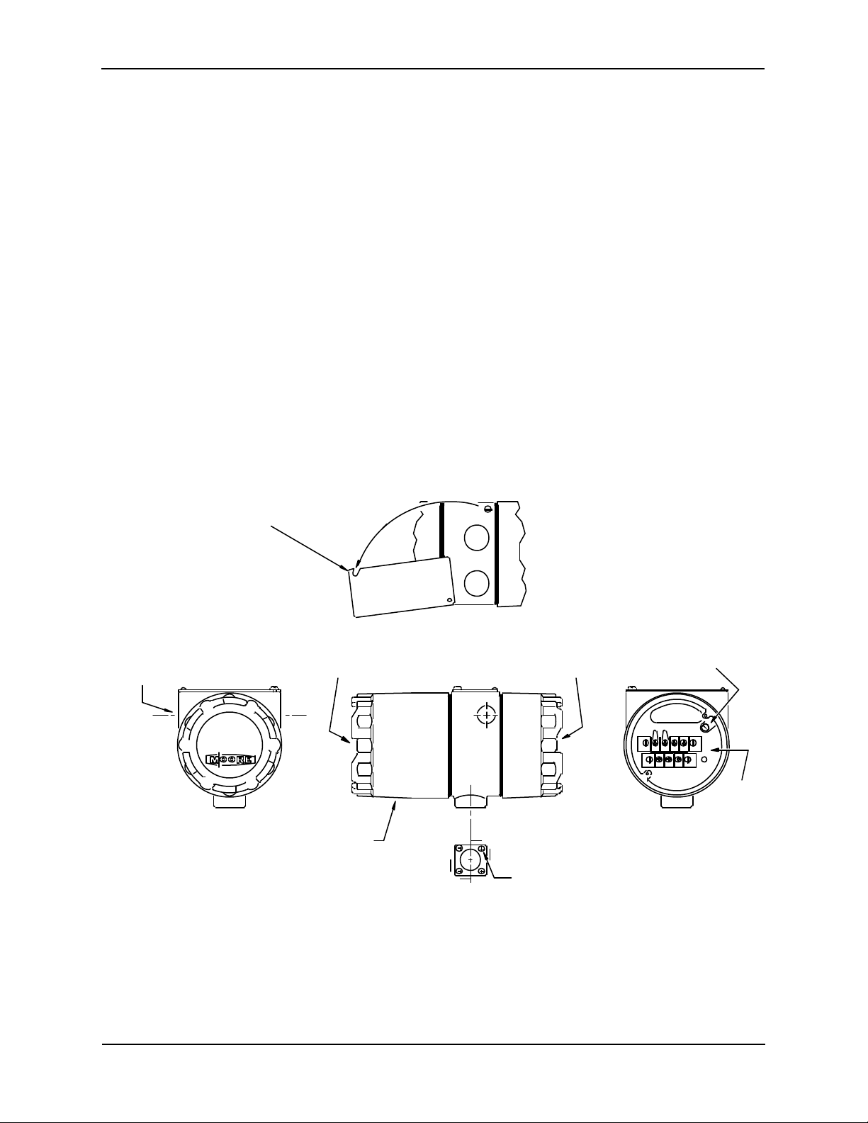
This User’s Manual is for the XTC™ Model 344 Smart Temperature Transmitter. It covers both the
Transmitter-Controller and Transmitter only versions.
NOTE
Throughout this Manual the term Transmitter will include both versions
except when the Transmitter-Controller is specifically stated and when
discussing unique Transmitter-Controller features, such as the Controller
function block.
All information needed to bench test, install, configure, system test, and service a transmitter is included in
this User’s Manual. Figure 1-1 shows the basic Model 344. Figure 1-2 shows the two terminal strips for
loop, sensor, display, and test equipment connections .
IMPORTANT
Save this User's Manual for installing, configuring, operating and servicing
a Model 344 transmitter.
1.1 SECTION CONTENTS
Nine sections make up this Manual. A brief description of each section follows.
Section 1, INTRODUCTION, describes each section in this Manual and provides a brief description of
the Model 344 Smart Temperature Transmitter line.
Section 2, XTC COMMUNICATOR (MXC), describes use of the MXC to test, configure, and calibrate a
transmitter.
Section 3, INITIAL TRANSMITTER SETUP, provides procedures to perform a bench test of the
transmitter to ensure pr oper operation of all functions. Start-up configuration is described here. If desired,
go to Section 5 to perform a complete configuration.
Section 4, INSTALLATION, furnishes specific information for mechanical and electrical installation.
Section 5, ON-LINE AND OFF-LINE OPERATION, describes on-line and off-line configuration, and
the use of the transmitter’s zero and full-scale pushbuttons.
Section 6, CALIBRATION AND MAINTENANCE, provides calibration procedures for analog and
digital modes. It also furnishes preventive maintenance, troubleshooting, and assembly replacement
procedures. A spare and replacement parts list is provided at the back of this Manual.
Section 7, CIRCUIT DESCRIPTION, contains an assembly level circuit description to support transmitter
servicing.
September 1995
Page 11
1-2
INTRODUCTION UM344-2
4 Places
Section 8, MODEL DESIGNATION AND SPECIFICATIONS, furnishes tables describing transmitter
model numbers, and it contains mechanical, functional, performance, and environmental specifications.
Hazardous area certifications are also lis ted.
Before installing or servicing a transmitter, read the information on the nameplate and ensure that the
correct model is at hand and that the correct procedures are followed.
Section 9, GLOSSARY, contains definitions of various transmitter related terms.
APPENDIX A describes transmitter function blocks and the parameters available.
APPENDIX B contains hazardous area installation drawings and information needed for barrier selection.
WARRANTY contains the product warranty statements and information concerning servicing of the
product during the warranty period.
PARTS LIST shows an exploded view of the transmitter and a list of on-hand spare parts and field
replaceable parts.
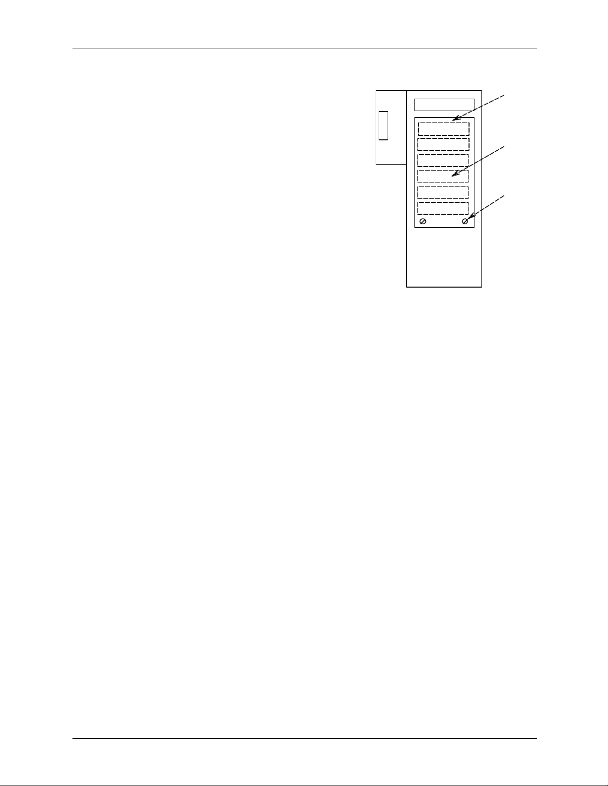
Rotate Nameplate to Access Zero
and Full Scale Pushbuttons
Electrical Entrance
1/2 NPT or M20 X 1.5
Tapped Hole
2 Places
Z FS
Digital Meter Option Electrical Connections
Enclosure Cap
Quanitity 2
Mounting Hole
1/4-20 Thread
FIGURE 1-1 Basic Model 344
X02801S1
Ground Connection
TESTSIGNAL
+ -
321
Terminal
Strips
Shown with Enclosure
Cap Removed
September 1995
Page 12

1-3
UM344-2 INTRODUCTION
Ohms,or mV Input
MXC
Connections
Signal (+)
Terminal
Signal (-)
Terminal
Test (+)
Terminal
SIGNAL
+
TEST
Test (-)
Terminal
Ground
Screw
Notes:
-
Sensor Terminals for
Thermocouple, RTD,
1. Viewed with enclosure cap
removed.
2. MXC = Moore XTC
Communicator.
X02869S1
FIGURE 1-2 Terminal Connections
1.2 PRODUCT DESCRIPTION
The Model 344 Temperature Transmitter, shown in Figure 1-1, is a microprocessor -based measurement
and control device which combines accurate, reliable temperature measurement and a PID controller in
one unit. The Transmitter accepts an RTD, thermocouple, millivolt, slide wire or resistance sensor input.
It contains a custom ASIC (Application Specific Integrated Circuit) which contains standard temperature
calibration curves for J, K, E, T, R, S, B and N type thermocouples and US/DIN curves for 100, 200, and
500 ohm Platinum RTDs. The sensed signal is linearized and corrected for ambient temperature changes
by the microprocessor and then converted to an equivalent 4-20 mA or HART® (Highway Addressable
Remote Transducer) digital output signal.
The analog output signal, HART digital communications, and 24 Vdc power (typical) are carried on a
twisted-pair 2-wire cable. The HART digital communication signals are superimposed (AC coupled) onto
the 4-20 mA loop current allowing simultaneous communication with the Transmitter without
compromising loop integrity. A digital meter is available when local indication of transmitter output is
required. Loop wiring connections made to the electrical terminals shown in Figure 1-2.
A transmitter can be configured to operate in either an analog mode or a digital mode, for a Point-To-Point
or a Multi-Drop network respectively.
ANALOG MODE: A single transmitter is connected to a controller, recorder or other field device. A loop
known as a Point-To-Point Network interconnects the instruments. The transmitter's output is the process
variable and it is sent to a controller or recorder using a standard 4-20 mA analog current.
September 1995
Page 13

1-4
INTRODUCTION UM344-2
The HART protocol is used for communication between the transmitter and a Moore XTC Communicator
(MXC), a personal computer running MXTC Configuration Software or other remote device. A typical
communication can be to: transfer a new and edited configuration, remotely monitor the process variable,
or service a transmitter.
DIGITAL MODE: One to fifteen transmitters can be parallel connected to a Multi-Drop Network using
only twisted-pair cable. The HART protocol is employed to send all process variable information to a
HART-compatible controller, recorder, or other device.
A mounting bracket is included and permits either pipe mounting (2" pipe) or wall mounting. When
attached to a thermowell, the Transmitter can be mounted directly to a process vessel, chamber, or flow
pipe.
1.3 CONFIGURATION
A smart transmitter must be configured before being used on-line or off-line. Each transmitter is shipped
with either a default configuration or, if specified at time of order, a custom configuration defined by the
user. A default configuration may need to be edited by the user befor e the transmitter is used in a loop.
1.4 PRODUCT SUPPORT
Product support can be obtained from the Moore Products Co. Technical Information Center (TIC). TIC is
a customer service center that provides direct phone support on technical issues related to the functionality,
application, and integration of all products supplied by Moore Products Co.
To contact TIC for support, either call 215-646-7400, extension 4TIC (4842) or leave a message in the
bulletin board service (BBS) by calling 215-283-4958. The following information should be at hand when
contacting TIC for support:
• Caller ID number, or name and company name
When someone calls for support for the first time, a personal caller number is assigned. This number is
mailed in the form of a caller card. Having the number available when calling for support will allow the
TIC representative taking the call to use the central customer database to quickly identify the caller’s
location and past support needs.
• Product part number or model number and version
• If there is a problem with a product’s operation:
• Is the problem intermittent or constant?
• What steps were performed before the problem occurred?
• What steps have been performed since the problem occurred?
• What symptoms accompany the problem? Is an error message displayed?
• What is the installation environment? For example:
- type of plant and process, involved loop, control strategy, and related equipment.
- workstation or personal computer manufacturer and model, amount of memory, and
operating system.
For product support outside of North America, contact your nearest Moore Products Co. subsidiary.
September 1995
Page 14
UM344-2 XTC COMMUNICATOR
Personal Computer
2.0 XTC COMMUNICATOR
The Moore XTC Communicator (MXC) is a HART protocol-based, hand-held instrument capable of
communicating with HART conformant instruments from Moore Products Co. and from other
manufacturers. It provides full access to on-line and off-line configuration data and to monitoring of
process variables. An MXC is shown in Figure 2-1.
When used with HART-conformant field instruments, the MXC can:
• Store up to 100 instrument configurations in its non-volatile memory.
• Download a stored configuration from the MXC to an on-line instrument (e.g., a transmitter).
• Upload a configuration from an on-line instrument to the MXC
• Store configurations created at and downloaded from a personal computer running Moore XTC
Configuration Software.
• Communicat e with a field instrument from any point in the loop.*
Stored
Configurations
(Archives)
X02856S0
Configuration Transfer
MXC
Moore XTC
Communicator
Configuration Transfer
Model 344
Temperature Transmitter
The MXC and the field instruments with which it communicates use the HART protocol for remote
communications. HART uses Frequency Shift Keying (Bell 202 standard) to superimpose digital signaling
on the standard 4-20 mA analog signal. Since there is no net energy change, the analog signal will not be
disturbed and loop integrity is maintained.
An MXC can be used on-line and off-line. On-line, it can display process data from a field instrument or
transfer a configuration between the MXC and a field instrument. Off-line, it is used to create a
configuration or to edit a configuration stored in the MXC. Off-line, an MXC can communicate with a
personal computer to transfer configurations between the MXC and personal computer.
In the following sections, MXC hardware and software will be described. Included in this description will
be the display, keypad, wiring, and power requirements. In addition, at the end of this section, major MXC
menu screens are shown in Figure 2-2 and Model 344 parameters accessible through the MXC are
shown.
* Between the sense resistor and instrument in a non-hazardous area installation. Between the sense resistor and a barrier
in a hazardous area installation.
September 1995
Page 15
XTC COMMUNICATOR UM344-2
2-2
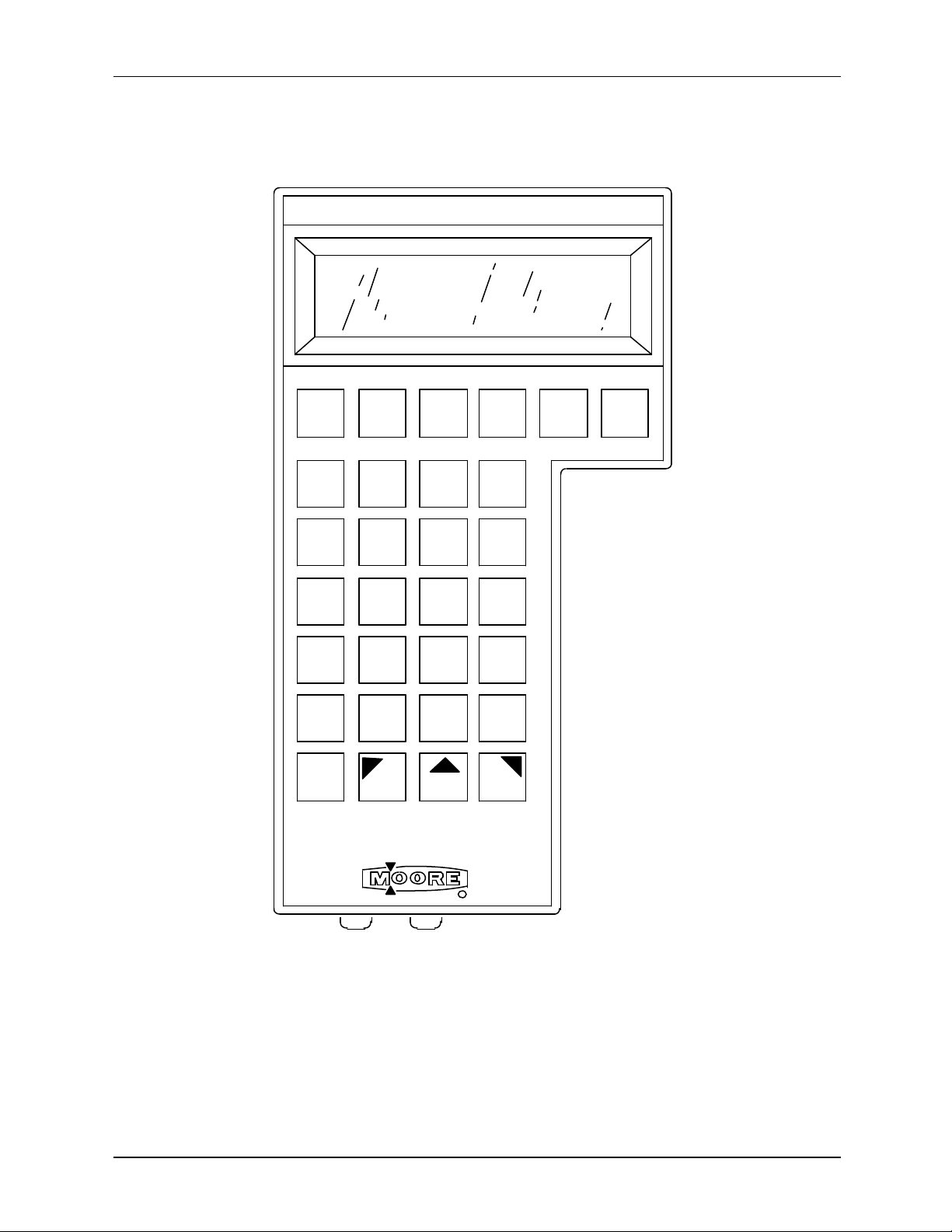
MOORE XTC COMMUNICATOR
ON F1
TRANS.
VAR'S
CHANGE
SP
CHANGE
VALVE
A/M
TUNE
BACK
LIGHT SHIFT SHIFT SHIFT
TREND ZOOM
A B C
1
J K L
4
S T U V W X Y Z #
7
@ % &
__
F2 F3
STATUS
D E F G H I
2 3
M N O P Q R
5
8 9
SPACE0+ / *
F4
OFF
6
.
X02665O0
Figure 2-1 Moore XTC Communicator (MXC)
September 1995
Page 16

UM344-2 XTC COMMUNICATOR
2.1 DISPLAY
The MXC has a 5 by 8 dot matrix Liquid Crystal Display (LCD) with
four lines of twenty characters each to show configuration
parameters, operating status , on-line variables, and trends. The LCD
has a back light that can be turned on for viewing in dimly lighted
SELECT BLOCK TO EDIT
- SENSOR INPUT SELPREV NEXT END ECT
areas.
All MXC screens have a similar layout. As shown here, most configuration screens use the top two lines
to describe the current screen, and the lower two lines to show the selections available from this screen.
Selections are entered by pressing keys on the MXC keypad. Some on-line variable and trend screens are
slightly different from that shown here, but they will always have a selection to access the next screen.
A blinking infinity symbol (∞) at the lower right corner of the screen indicates that the MXC is
communicating with a field instrument or a personal computer. No keyboard keys should be pressed until
the symbol is cleared upon completion of the communication.
2.2 KEYPAD DESCRIPTION
The thirty-key keypad is shown in Figure 2-1. It contains dedicated keys, alphanumeric keys with shift
keys, and function keys. These keys are color coded as follows:
Ÿ Red - dedicated ON key
Ÿ Black - dedicated OFF key
Ÿ Gray - function keys and dedicated keys (for controller block, on-line monitoring, and MXC functions)
Ÿ White - dedicated alphanumeric, symbol, and shift keys
A dedicated key performs a given function no matter what screen is showing. A function key is
dependent upon the action being performed and the MXC's firmware; available selections are shown on
the screen's bottom two lines.
2.2.1 Dedicated Keys
ON - This key powers up the MXC and initiates the MXC self -test. Press and hold the key until the
Moore logo appears and then release it. If the MXC fails self -test, a warning message will be displayed.
The MXC will now show the options available: communicate with a field instrument or personal computer
or do off-line configuration. These topics are discussed further in Section 5.
To conserve battery power, the MXC will shut off after 10 minutes if no keypad key is pressed. This
auto-shut-off is disabled when the MXC is on-line (e.g., displaying a process variable).
OFF - This key powers down the MXC. It may be used at any time. During configuration, however,
care should be taken so important information is not discarded. When the MXC is in certain modes and
communicating with a field instrument or personal computer, it will query the user as to whether or not it
should be turned off in this mode.
September 1995
Page 17

XTC COMMUNICATOR UM344-2
2-4
BACK LIGHT - This key turns on the LCD back light for easier viewing of the display in a dimly lighted
area. The back light is activated by pressing the key and is deactivated by again pressing the key.
NOTE
The back light consumes significant power. To extend battery life, use
the back light only when needed.
TRANS. VAR'S. - The Transmitter Variables key is a quick access key that is pressed to display a
screen showing the transmitter's on-line parameters: measured variable (MV), current output (I), process
variable (PV) and their respective units. Exit this screen by again pressing the TRANS. VAR'S. key or
by pressing the F4 key, for END. If the transmitter is conf igured as a transmitter-controller you will be
prompted to choose either transmitter variables or controller variables. Controller variables include process
variable, setpoint and valve.
TREND - The TREND key is another quick access key that is pressed to trend a variable and show up to
thirteen samples. Any one of the following variables can be trended: the measured variable (MV), the
current output (I), or the process variable (PV). The trend sampling rate can be set to 1-300 seconds
between samples. Exit this screen by again pressing the TREND key or by pressing the F4 key, for END.
ZOOM - The ZOOM key is a quick access key that allows a closer examination of a variable chosen in
the Trend screen. This key functions only when a Trend screen is displayed.
ZOOM magnifies a range of values equal to 10% of the span. The midscale value is user selected.
For example, when viewing a range of 0-100% in the Trend screen, the value of 50% is chosen to zoom
on. The Trend screen now shows a range of 45-55%. Exiting the Zoom screen again displays the Trend
screen. Exit the Trend screen to return to the Main Menu.
STATUS - The STATUS key is a quick access key that is pressed to display the Status screen. This
screen will show the instrument tag name, model number, software revision number, serial number, and
functional statuses such as fixed current mode and error conditions. Exit the Status Screen by again
pressing the Status key or by pressing the F4 key.
CHANGE SP, CHANGE VALVE, A/M, and TUNE Keys - These are dedicated keys that are
reserved for use with XTC Model 340 and 344 Transmitter-Controllers. These keys are inactive when
communicating with an instrument that does not have a controller function block.
CHANGE SETPOINT - Press the CHANGE SP key to view and change the value of the online setpoint of the controller in either automatic or manual mode. If the controller is in MANUAL with
tracking setpoint, then the setpoint cannot be changed. The SP is displayed in the same units as the
transmitter dis play configured in the operator’s display function block. Press the “CHANGE SP” key
again, or F3, to exit this mode.
CHANGE VALVE - This key allows you to view and change the position of the valve. If the
controller is in AUTO, the valve cannot be changed. Press the “CHANGE VALVE” key again, or
F3, to exit this mode.
September 1995
Page 18

UM344-2 XTC COMMUNICATOR
AUTO/MANUAL - The A/M key toggles the controller between automatic and manual control.
Press the “MANUAL”, key F1, or “AUTO”, key F2 to change state. Press “A/M” key again, or F4,
to exit this mode.
TUNE - This key allows tuning of the controller. The first screen displays the controller action,
DIRECT or REVERSE. The controller action may be viewed from the TUNE key, but it must be
changed in the configuration mode. Press F4 to continue.
The Proportional Gain (PG), Time Integral (TI) and Time Derivative (TD) can be changed from this
screen. Press F1, F2 or F3 to display the current value and edit the parameter. Press “CONT”, key
F4 to continue.
The Derivative Gain (DG) and Manual Reset (MR) can be changed from this screen. Press F1 or F2
to display the current value and edit the parameter. Press F4 to go to the previous screen. Press the
“TUNE” key again, or F3, to exit this mode.
ALPHANUMERIC Keys - Twelve white keys with alphanumeric characters and symbols are located
toward the center of the keypad area. Pressing a 1-9, 0, -, or . key will display that character on the
screen. These keys also have alphabetic characters and symbols that require the use of a SHIFT key.
These numbers, letters and symbols are typically used in writing a range, damping value, tagname,
message, or descriptor.
SHIFT Keys - Three shift keys are located below the alphanumeric keys. They are used to access a
letter or symbol located in the upper left, center, or right portion of an alphanumeric key. To select an
alphabetic character or upper symbol, press the proper SHIFT key (left, center, or right arrow) and then
press the desired alphanumeric or symbol key.
2.2.2 Function Keys
F1, F2, F3, and F4 - The function keys are the gray keys located just below the MXC display. The
function or action performed by each key is shown on the bottom two lines of the display, immediately
above each key. For example, when the MXC is first turned on and the Main Menu screen appears, the
following selections are aligned with the function keys: F1 - FIND
XMTR, F2 - ARCH FUNC, F3 - TEST MXC, and F4 - END. To
make a selection, press the corresponding Function key and the next
screen will appear. These keys are used extensively when
configuring or monitoring a field instrument.
SELECT FUNCTION
FIND ARCH TEST
XMTR FUNC MXC END
September 1995
Page 19
XTC COMMUNICATOR UM344-2
2-6
2. Connect the MXC only in a non-hazardous area.
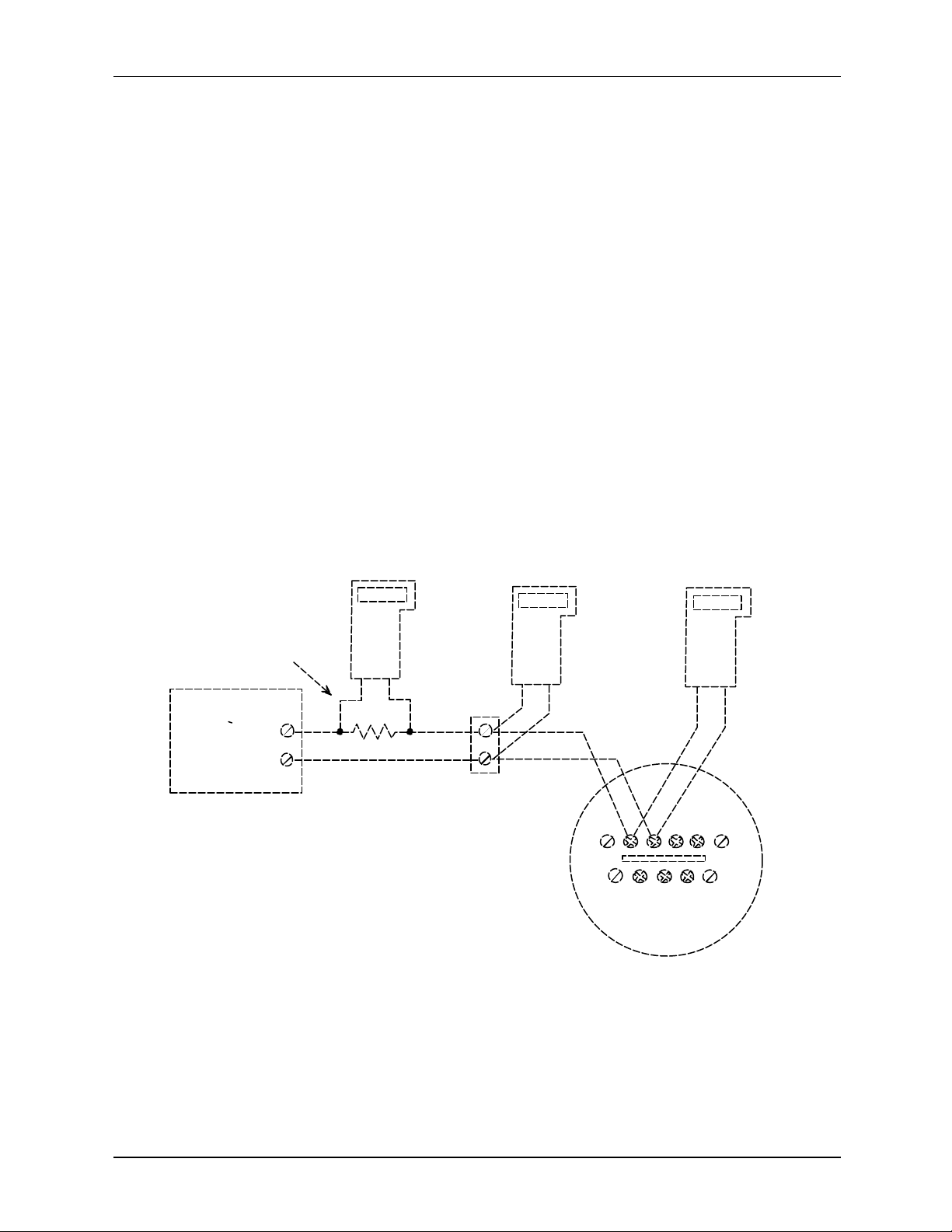
2.3 LOOP CONNECTION
The MXC is quickly connected into a transmitter loop. A 40" (1m) cable with a dual banana plug on one
end and two mini-grabber clips on the other is provided. The dual banana plug is inserted into the bottom
of the MXC. The mini-grabber clips are connected to the Model 344's signal terminals or to the loop's
current sense resistor, usually at a receiving instrume nt such as a Model 352 Single -Loop Digital Controller
(see notes below). This is a non-polar connection. The MXC can now communicate with the transmitter
from the control room or a field location. The diagram below shows a basic loop with the MXC connected
at various locations.
NOTE
The HART protocol requires a network (loop) resistance between
250Ω and 1100Ω to support communications. See Section 4.3.5 to
determine resistance value.
IMPORTANT
In a hazardous area installation, connect the MXC on the safe side
of the barrier, between the current sense resistor and the barrier.
Current Sense
Resistor, 250 to
1100 Ohms
Controller,
Recorder,
Indicator,
or other
Device
Notes:
1. Connect an MXC to any of the locations shown.
+
_
MXC
MXC
X02849S1
MXC
Signal Test
_
+
+
Model 344
Terminals
_
September 1995
Page 20
UM344-2 XTC COMMUNICATOR
2.4 POWER
Six "AA" alkaline batteries are supplied with the MXC. Remove
the rear cover to access the battery compartment, as shown in the
figure. Typical operating time of the MXC with new batteries and
the back light off is approximately 80 hours; with new batteries and
the back light on, approximately 30 hours.
A Low Battery indicator (LB) is displayed in the lower right corner
of the LCD when about one -half of the battery charge is spent.
Fresh batteries should then be available for installation.
++
+
+
+
+
+
Battery
Access
Cover
Batteries
Captive
Screw
NOTE
If the MXC fails due to low batteries, data in the On-Line
Memory section of the MXC will be lost. The MXC
should not be used to troubleshoot critical loops while the
low battery indicator is showing.
The MXC will automatically conserve battery life when in the configuration mode. After approximately
ten minutes with no keys on the keypad being pressed, the MXC will shut itself off. This will not occur
while the MXC is monitoring variables from a field instrument.
2.5 MXC SOFTWARE VERSION
To read an MXC's software version, perform the following steps.
1. Press and hold the MXC's ON key until the MOORE logo appears on the display.
2. Watch the MXC display. The MXC's software version will be momentarily displayed.
3. Press the OFF key or continue on to configure or monitor a transmitter.
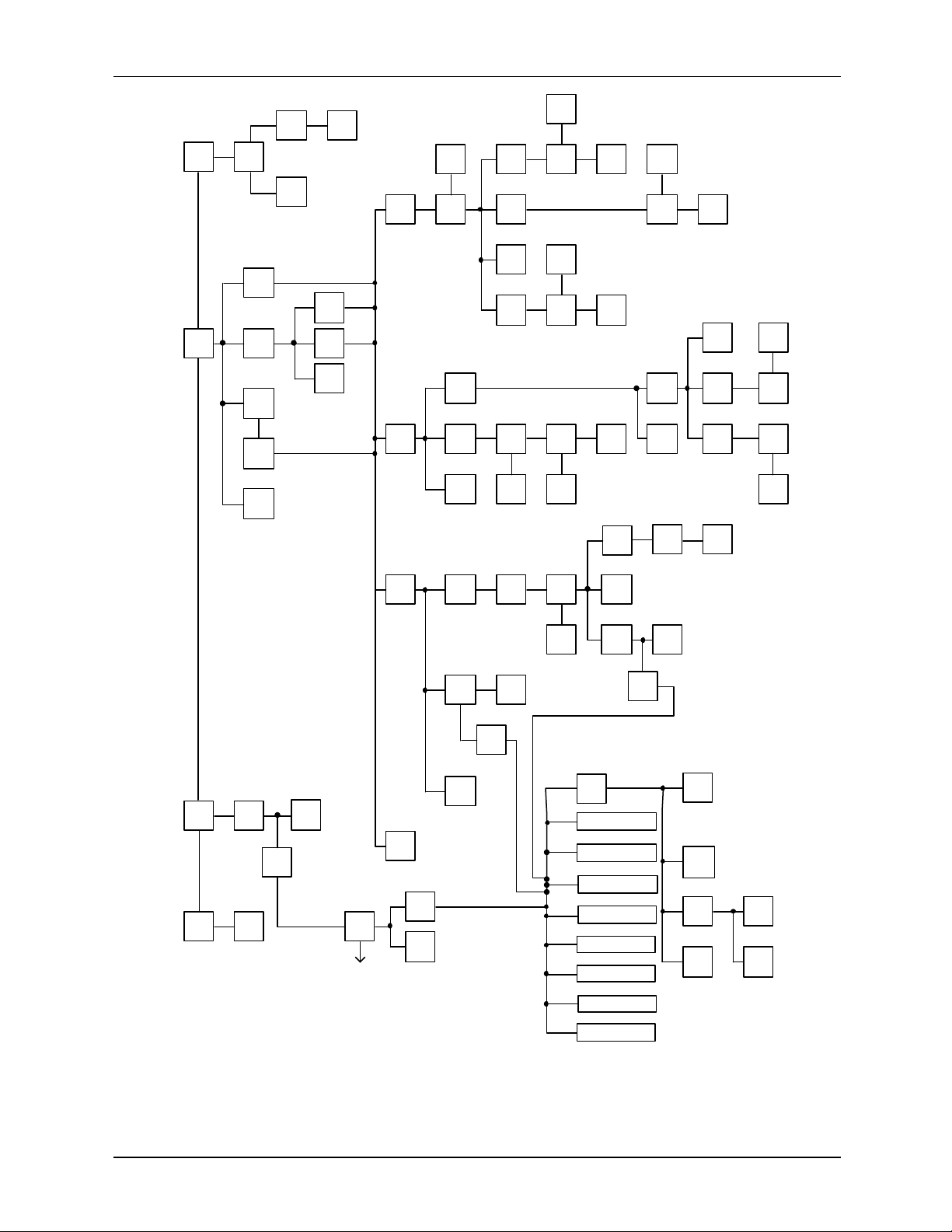
2.6 MXC MENU SCREENS AND PARAMETER MAP
Major MXC menu screens are shown in Figure 2-2. The screen's name appears in the left column.
These screens are shown in block form in Figure 2-3.
Figure 2-3 is a Parameter Map which shows general configuration and calibration flow. Detailed
configuration procedures are given in Section 5 of this Manual. Calibration is described in Section 6.
September 1995
Page 21

XTC COMMUNICATOR UM344-2
2-8
OVRD
QUIT SAVE VIEW LOAD
Main Menu
On-Line Menu
On-Line Configuration Menu
Calibrate/Test Menu
Function Block Menu
Configuration Complete Menu
Loop Override Menu
MXC screens X02781S0
SELECT FUNCTION
FIND ARCH TEST
XMTR FUNC MXC END
Dev ID: 210300003C
Tag: TTC-101 ADD: 00
LOOP CAL/ CON -
TEST FIG
CONFIGURATION MODE
END
EDIT EDIT
ARCH CONF END
CALIBRATE / TEST
CAL TEST END
SELECT BLOCK TO EDIT
- SENSOR INPUT SELPREV NEXT END ECT
CONFIGURATION
COMPLETE
RE- DOWN
LOOP OVERRIDE - CHOOSE
CURRENT OUTPUT LEVEL
4 MA 20 MA OTHR END
FIGURE 2-2 Major MXC Menu Screens
September 1995
Page 22
UM344-2 XTC COMMUNICATOR
MAIN MENU
TEST
MXC
MXC SELF TEST MENU
TEST
KEYS
TEST
SCRN
END
END
ON-LINE
MENU
LOOP
OVRD
PROCEED
LOOP
OVERRIDE
MENU
20mA
4mA
ABORT
ENTER
END
ABORTABORT
ENTER
END
ANA-
LOG
FIND
XMTR
DIGI
-TAL
SRCH
TAG
ENTER
TAG
END
NOTE:
This Map is intended to show
general configuration and
calibration flow. Every key
and screen is not shown.
SHORT
ADDR
POLL
END
CALIBRATE/TEST
MENU
CAL/
TEST
CONF
CAL
TEST
END
ON-LINE
CONFIGURATION
MENU
EDIT
ARCH
EDIT
CONF
END
OTHER
PROCEED
ABORT ABORT
ENTER
ARCH#
QUIT
QUIT
ENTER
mA
SELF
TEST
CONT
ABORT
END
END
PRO-
CEED
DOWN
LOAD
END
EDIT
ARCH
CONT
ABORT
DOWN
LOAD
QUIT
CONT CONT
TRIM
DAC
ZERO
ABORT
ABORT
CONT
ABORT
ARCH
FUNC
END
X02882S1
September 1995
ENTER
ARCH#
RE-
START
EXIST
NOT
EXIST
TEMPERATURE TRANSMITTER
SELECT
TYPE
END
EDIT
ARCH
END
CONT
END
FUNCTION BLOCK
MENU
END
SENSOR INPUT
OUTPUT
OPERATOR DISPLAY
TRANSMITTER ID
ALARM
SP TRACK & HOLD
A/M TRANSFER
CONTROLLER
FIGURE 2-3 Parameter Map, MXC/Model 344
CONFIGURATION
COMPLETE MENU
SAVE
REVIEW
DOWN
LOAD
QUIT
DOWN
LOAD
ABORT
Page 23

XTC COMMUNICATOR UM344-2
2-10
September 1995
Page 24

UM344-2 INITIAL TRANSMITTER SET-UP
3-1
3.0 INITIAL TRANSMITTER SET-UP
Before operating a Model 344 on-line, the instrument should be commissioned using the MXC and set-up
either at the bench or in the field. Commissioning consists of checking that the transmitter and the loop
are operational and that all configuration information is correct. This section contains step-by-step
procedures describing commissioning of the transmitter. For an in -depth discussion of transmitter
configuration, refer to Section 5.1 On-Line Operation.
3.1 COMMISSIONING TRANSMITTER ON THE BENCH OR IN THE FIELD
A Model 344 can be commissioned either before or after installation into the loop. Commissioning on the
bench before installation is suggested. A complete transmitter functional test can be performed and
configuration procedures can be practiced. If commissioning after installation, install the transmitter as
described in Section 4 and then return to this section. Configuration data for the transmitter will be
needed.
To commission the transmitter on the bench, make the connections shown in Figure 3-1. To commission
the transmitter in the field, make the connections shown in Figure 3-2 or those shown in Section 4.3.3,
Figure 4-1, 4-2, or 4-3. Connect the MXC in the loop either across the current sense resistor or, often
more conveniently, across the two signal terminals of the Model 344 (non-hazardous area only).
3.1.1 Test Equipment Needed
TEST EQUIPMENT DESCRIPTION (see Specifications, Section 8.3.2)
Power Supply 12 to 42 Vdc, see Section 4.3.4
Multimeter:
Current
Voltage
Current Sense Resistor
Accuracy of at least .05% to check calibration
Range: 4 to 20 mA to measure loop current
Range: 10-40 Vdc to measure power supply and loop voltage
250 to 1100Ω to support HART digital communications
Configuration Device Moore XTC Communicator (MXC)
User Configuration Configuration data for transmitter under test
NOTE
Test equipment should be 2 to 10 times more accurate than the desired
transmitter accuracy.
September 1995
Page 25
INITIAL TRANSMITTER SET-UP UM344-2
3-2
MXC
250
Bench Power
Supply (DC)
X02807S1
_
+
Signal Test
_
+
+
_
Model 344
Terminals
Resistance
Decade
Box
+
_
Digital
Milliammeter
FIGURE 3-1 Bench Test Connections
Controller,
Recorder,
Indicator, or
other 1-5 Vdc
Device
System
Power
Supply
X02808S1
Circuit
Junction
+
250
_
_
+
MXC
Signal
_
+
Test
_
+
Model 344
Terminals
+
_
Sensor
Wires
Digital
Milliammeter
FIGURE 3-2 Typical Field Test Connections
September 1995
Page 26

UM344-2 INITIAL TRANSMITTER SET-UP
3-3
3.2 ESTABLISHING
COMMUNICATION
SELECT FUNCTION
FIND ARCH TEST
XMTR FUNC MXC END
SEARCH FOR WHAT TYPE
OF TRANSMITTER?
ANA- DIG- SRCH
LOG ITAL TAG END
ENTER TAG TO SEARCH
WITH:
EN < > QUIT TER
1. Connect the transmitter as shown in either Figure 3-1
or 3-2.
2. Apply power to the loop.
3. Press and momentarily hold the MXC's ON key.
The first screen that will appear after the initial
power up screens is the Main Menu, shown
adjacent. Press FIND XMTR (F1) to have the
MXC initially establish communication with the
Model 344.
4. From the next screen, select either Analog, Digital,
or Search Tag to begin communication with the
transmitter. Read the following and then press one
of the four following keys (F1, F2, F3, or END).
ANALOG (F1) - Press to search for an analog
mode transmitter. Analog mode is used when there
is one transmitter in the loop and it has an address of
zero. If all Point-to-Point Network connections are
correct, when the MXC finds a transmitter with an
address of “0”, the MXC will display the ID and
TAG. Go to Step 6.
If a problem exists in the Transmitter or Network
Wiring, the MXC will show “NO TRANSMITTER
FOUND”. Go to Section 6.3 Troubleshooting to
confirm and resolve wiring problems.
DIGITAL (F2) - Press to search for a digital (multi -
drop) mode transmitter. Digital mode allows up to 15
transmitters to be connected to the loop. Each
transmitter in a loop is assigned a unique address
between 1 and 15. Go to Step 5.
SRCH TAG (F3) - Press to search for a specific
transmitter. Search can be used when the
transmitter is in either Analog or Digital mode. Type
the tagname (8 character alphanumeric string) of the
transmitter that is to be configured or interrogated
and press ENTER (F4). To edit the tagname, use
the arrow keys to select any character that needs to
be changed. Go to Step 6.
If a problem exists in a transmitter or loop wiring the
MXC will show “NO TRANSMITTER FOUND”.
END - Press to return to the previous screen.
September 1995
Page 27
INITIAL TRANSMITTER SET-UP UM344-2
3-4
SHORT OR LONG FORM
ADDRESS?
SHRT LONG
ADDR ADDR POLL END
ENTER TRANSMITTER
ADDRESS (1-15)
EN < END TER
ENTER TRANSMITTER
ADDRESS:
EN < END TER
SEARCHING FOR
TRANSMITTER
PLEASE WAIT
XMTR ID: 210100044F
TAG: MPCO 340 ADD: 01
LAST NEXT SELXMTR XMTR END ECT
NOTE
Analog and Digital modes are
discussed in detail in Section 4.
5. The MXC will next prompt for a digital method of
searching. Press one of the following keys.
SHRT ADDR (F1) - Press and then enter the short
address (1-15) stored during configuration.
IMPORTANT
The factory default setting for the short
address is 0, analog mode.
LONG ADDRESS (F2) - Press and then enter the
long address stored in memory at the factory. (The
long address, the Dev. ID shown in the On-Line
Menu and the XMTR. ID shown by polling are the
same.) This address can not be altered.
POLL (F3) - Press to instruct the MXC to look for
any live addresses on the multi-drop network (1-15).
While the MXC is searching for one or more
transmitters, it will display SEARCHING. The MXC
will then display the long and short addresses of all
live transmitters on the network; select one by
pressing the SELECT (F4) key.
To view each of the live transmitters, press the
LAST XMTR and NEXT XMTR keys to scroll
forward and backward. Each screen will show the
transmitter ID number (i.e. device ID or long
address in hexadecimal), tagname, and short address.
Check IDs against user documentation to confirm
that all transmitters are present
If a problem exists in a transmitter or its wiring it will
be excluded from the poll. If a major fault exists in
the network wiring, the MXC will display the
warning message “NO TRANSMITTER FOUND”.
Go to section 6.3 Troubleshooting to confirm and
resolve wiring problems.
6. Communication has now been established between
the transmitter and MXC and the transmitter's
configuration has been uploaded to the MXC's OnLine Memory.
September 1995
Page 28
UM344-2 INITIAL TRANSMITTER SET-UP
3-5
OVRD
The next screen to appear is used to save the
WOULD YOU LIKE TO
SAVE TRANSMITTER
DATA IN
ARCHIVES NO YES
configuration to an archive. If the configuration is to
be edited, press YES (F4) to save the configuration
in case a mistake is made. The next screen will
prompt for an archive number (0-99). The archive
number chosen will be the location where the MXC
ENTER ARCHIVE NUMBER
(0-99):
EN < > END TER
stores the transmitter's configuration data. Archiving
will be discussed in more detail in the Off-Line
portion of section 5.
The MXC can now be used to calibrate or configure the
transmitter, monitor loop parameters, or test loop
Dev ID: 210300003C
Tag: TTC-101 ADD: 00
LOOP CAL/ CON -
TEST FIG
END
functionality. Section 5 of this Manual describes
configuring and monitoring of the transmitter, and
calibration is described in Section 6. The screen
selections to choose the options of configuration,
calibration, and loop checkout are found on the On-Line
menu screen.
3.3 TESTING THE
TRANSMITTER, MXC, AND THE
LOOP
The test routines available through the MXC are used to
verify that the Transmitter, the MXC , and the loop are all
working properly. Whenever a problem with any of the
instruments or the loop is suspected, test the equipment
to make sure there are no component failures. The test
functions can be accessed in two locations in the MXC,
and these are described below.
3.3.1 MXC Testing
SELECT FUNCTION
FIND ARCH TEST
XMTR FUNC MXC END
MXC SELF TEST
PRESS ANY KEY TO
CONFIRM CONTACT
_ _ _ _ _ _ _ _ _ _ END
TEST
1. Press and momentarily hold the MXC's ON key.
The Main Menu will appear.
TEST TEST
KEYS SCRN END
2. Press TEST MXC (F3) to display the MXC Self
Test screen.
3. Press one of the following keys.
TEST KEYS - Press to test MXC keys. At the next
screen, press any key on the keyboard and the
September 1995
Page 29

INITIAL TRANSMITTER SET-UP UM344-2
3-6
screen will display a character
associated with that key. The
screen will show up to 10 characters
before erasing the oldest.
September 1995
Page 30

UM344-2 INITIAL TRANSMITTER SET-UP
3-7
MXC SCREEN TEST
ABOUT TO BEGIN
MXC SCREEN TEST
COMPLETED
3.3.2 Transmitter Testing
CALIBRATE / TEST
CAL TEST END
TEST - PERFORMS
DIAGNOSTIC TEST ON
TRANS- A- PROMITTER BORT CEED
WARNING! SELF TEST
MAY BUMP TRANSMITTER
OUTPUT A BORT CONT
TRANSMITTER PASSED
TRANSMITTER SELFTEST
CONT
TEST SCRN - Press to test all screen segments.
When this key is pressed, the MXC displays the
"Begin" message to the left, then lights all the
segments, turns them all off, displays the
"Completed" message, and the n returns to the
original test screen.
END - Press to exit the test mode and return to the
Main Menu screen.
Although the Transmitter continuously performs an online self test, a more extensive self test can be performed
after communication with the MXC has been established.
1. At the On-Line Menu, press CAL/TEST (F2) to
display the Calibrate and Test selections.
2. At the Calibrate/Test Menu, press TEST. A Test
caution screen will appear. Press one of the
following:
ABORT - Press to return to the Calibrate/Test
Menu.
PROCEED - Press to continue the self test. A
warning screen will be displayed then a message
states that the test is occurring. After the test, the
MXC will show whether or not the transmitter has
passed or failed the self test.
If the MXC indicates that the Transmitter has:
Passed - Press CONT then END.
Failed - Check installation wiring thoroughly. Go to
Section 6 for troubleshooting suggestions.
3. When the MXC displays the Transmitter’s ID (OnLine Menu), press the STATUS Key to check for
Transmitter errors. If an error is present, the
ERROR Key (F2) will be displayed. Press
ERRORS (F2) to check for ROM, RAM, EEPROM,
TIMER and SENSOR errors. Refer to Section 6.3
Troubleshooting to confirm and resolve the error.
4. If the alarm function is enabled, press ALARM (F1)
to check the ALARM OUT OF SERVICE status.
September 1995
Page 31

INITIAL TRANSMITTER SET-UP UM344-2
3-8
OVRD
3.3.3 Loop Testing
Testing the loop involves making sure that the
Transmitter is sending out the proper current signal and
that the other elements in the loop are receiving this
signal. The Loop Override mode is used to test the loop.
LOOP OVERRIDE SETS
TRANSMITTER OUTPUT
TO ENTERED VALUE END CONT
1. At the On-Line Menu, press LOOP OVRD. The
adjacent screen will be displayed. Press CONT and
then PROCEED.
2. Choose either 4 mA or 20 mA from the menu, or
WARNING! SELF TEST
MAY BUMP TRANSMITTER
OUTPUT A BORT CONT
choose OTHR to enter another value. After a value
is entered, the Transmitter will output the value
chosen. Read the analog current value on a:
Ÿ Recorder or control station in the loop
Ÿ Milliammeter connected in series in the loop
LOOP OVERRIDE - CHOOSE
CURRENT OUTPUT LEVEL
4 MA 20 MA OTHR END
Ÿ Milliammeter connected to the TEST terminals
(Figures 3-1 and 3-2)
Ÿ Analog Voltage may be read on a voltmeter
connected across the sense resistor.
NOTE
This is intended as a functional test. To
check calibration accuracy a DMM of at
least .05% accuracy must be used.
If the transmitter is not working properly, try to
recalibrate it (see Section 6.1).
3.4 REVIEW CONFIGURATION
DATA
Dev ID: 210300003C
Tag: TTC-101 ADD: 00
LOOP CAL/ CON -
TEST FIG
END
Before placing the Transmitter on-line, check that the
proper configuration information has been stored.
1. Establish communication between the Transmitter
and MXC.
2. Using the MXC screens, compare the uploaded
configuration with user's configuration
documentation.
September 1995
Page 32

UM344-2 INITIAL TRANSMITTER SET-UP
3-9
1) At the On-Line Menu, press CONFIG to access
the function blocks. Continue through the menu
sequence until reaching the Function Block
Menu.
2) Check the information in the eight function
blocks listed below. Edit values as needed while
reviewing.
3. Archive the revised configuration in the MXC
4. Download the configuration to the Transmitter.
TRANSMITTER FUNCTION BLOCKS*
SENSOR INPUT
Input Type
Measured Variable Units
Range Lo & Hi
Damping
Burnout Direction
OPERATOR DISPLAY
Process Variable Units
Range Lo & Hi
Auto Rerange
Local Display Code
TRANSMITTER ID
Tag
Descriptor
Message
Date
Device Serial Number
Short Address
OUTPUT
Failsafe Level
ALARM
Alarm 1 Enable/Disable
Alarm 1 SP
Alarm 1 Type
Alarm 2 Enable/Disable
Alarm 2 SP
Alarm 2 Type
Self Clearing NaKS
Alarms Out of Service
September 1995
Page 33

INITIAL TRANSMITTER SET-UP UM344-2
3-10
SP TRACK & HOLD
Tracking Setpoint
PUSP
A/M TRANSFER
Power-Up Mode
Automatic Only
Power-Up Valve
CONTROLLER BLOCK
Controller ON/OFF
Controller Type
Action
Prop. Gain
Time-Integral
Time-Derivative
Derivative Gain
Manual Reset
Manual Reset Track
* For more detailed information on these function
blocks, refer to Section 5 and Appendix A.
3.5 CHECKING TRANSMITTER
OUTPUT
At this point, check to be sure that the transmitter is
reading the proper sensor input in the proper units.
1. Set the sensor input to the transmitter to a known
value either by adjusting the process variable to a
field mounted transmitter or the simulated input to a
bench test transmitter.
VIEW WHICH VARIBLES
2. With the On-Line Menu displayed, press the gray
TRANS.VAR’s key on the MXC keypad to display
XMTR CONT
END
the VIEW WHICH VARIABLES screen.
3. Press one of the following keys depending upon
controller activation:
P: 63.301%
S: 50.000%
V: 10.000%
END
Controller Block ON: Press CONT (F2) to display
the controller variables.
P - Process
S - Setpoint
V - Valve
M: 76.534 deg F
I: 4.8377 mA
P: 76.534 deg F
END
Controller Block OFF: Press XMTR (F1) to display
the process variables.
M - Measured Variable
I - Current (mA)
September 1995
Page 34

UM344-2 INITIAL TRANSMITTER SET-UP
3-11
P - Process Variable
4. Check these Transmitter Variables to ensure the
readings are correct.
5. Press END (F4) to return to the main menu.
September 1995
Page 35

UM344-2 INSTALLATION
4-1
4.0 INSTALLATION
This Section describes installation of a Model 344 Temperature Transmitter. Topics include: receipt of
shipment, installation considerations, and mechanical and electrical installation.
IMPORTANT
The installation must conform to the National Electrical Code and all
other applicable construction and electrical codes.
Refer to the installation drawings in Appendix B when locating a
Transmitter in a hazardous area.
4.1 EQUIPMENT DELIVERY AND HANDLING
4.1.1 Factory Shipment
Prior to shipment, a Transmitter is fully tested and inspected to ensure proper operation. It is then
packaged for shipment. Most accessories are shipped separately.
4.1.2 Receipt of Shipment
Each carton should be inspected at the time of delivery for possible external damage. Any visible damage
should be immediately recorded on the carrier's copy of the delivery slip.
Each carton should be carefully unpacked and its contents checked against the enclosed packing list. At
the same time, each item should be inspected for any hidden damage that may or may not have been
accompanied by exterior carton damage.
If it is found that some items have been damaged or are missing, notify Moore Products Co. immediately
and provide full details. In addition, damages must be reported to the carrier with a request for their onsite inspection of the damaged item and its shipping carton.
4.1.3 Storage
If a Transmitter is to be stored for a period prior to installation, review the environmental specifications in
Section 8.3.5.
September 1995
Page 36

INSTALLATION UM344-2
4-2
4.2 ENVIRONMENTAL CONSIDERATIONS
Many industrial processes create severe environmental conditions. The conditions at each transmitter
location must be within the specifications stated in Section 8.3.5.
The Transmitter is designed to perform in harsh conditions, however, it is prudent to locate a Transmitter
to minimize the effects of heat, vibration, shock, and electrical interference.
CAUTION
Exceeding the specified operating temperature limits can adversely affect
performance and may cause damage.
4.3 INSTALLATION CONSIDERATIONS
Sections 4.3.1 and 4.3.2 outline basic considerations needed to achieve a successful mechanical/electrical
installation. The remaining sections then provide detailed pre-installation information.
4.3.1 Mechanical
• Select the sensor input: thermocouple, millivolt, RTD, or resistance. Refer to Section 8.2 for sensor
accessories.
• Determine if an optional digital meter for local monitoring of transmitter output is required. Refer to
Section 8.1 for model designation or 8.2 for accessory part numbers.
• Determine physical mounting of Transmitter. Consider:
• Using supplied bracket for pipe or wall mounting. Refer to Sections 4.4.1 and 4.4.2.
• Transmitter-to-process mounting. Refer to Section 4.4.3.
• Clearance for installation and maintenance and for reading the optional digital meter. Refer to
Figure 8-3.
• Need to rotate optional digital meter for viewing ease. Refer to Section 4.4.4.
Refer to Figure 8-3 for transmitter dimensions and the figures in Section 4.4 for typical mechanical
installations. Refer to Section 8.3 for mechanical and environmental specifications.
Ÿ Determine if an explosion-proof or intrinsically safe installation is required. Refer to Transmitter
nameplate for electrical classifications and Sections 8.1, 8.3, and 4.6.
An intrinsically safe installation requires user-supplied intrinsic safety barriers that must be installed in
accordance with barrier manufacturer's instructions for the specific barriers used.
Transmitter certification is based on the "Entity" concept in which the user selects barriers that permit
the system to meet the entity parameters.
September 1995
Page 37

UM344-2 INSTALLATION
4-3
Ÿ Determine conduit routing. Refer to Section 4.4.5.
Ÿ Prepare installation site drawings showing the following:
Ÿ Location of the Master Device (e.g. MXC or controller)
Ÿ Location and identification of each Transmitter
Ÿ Routing plan of signal cable(s)
Ÿ Location of any signal cable junctions for connecting the MXC
4.3.2 Electrical
Ÿ Determine Transmitter operating mode (analog or digital) and type of Network needed; refer to
Section 4.3.3.
Ÿ Determine minimum power supply requirements. Refer to Section 4.3.4.
Ÿ Select twinaxial cable type and determine maximum cable length. Refer to Section 4.3.5.
Ÿ Determine the need for network junctions. Refer to Section 4.3.6.
Ÿ Intrinsically Safe installations will need barriers. Refer to Section 4.3.7.
Ÿ Consider the effect of connecting additional equipment (e.g., recorder, loop powered display) to the
network. Refer to Section 4.3.8.
• Select sensor cable type. Refer to Section 4.3.9.
• Consider the accuracy limitation of a 2-wire RTD. Refer to Section 4.3.10.
• Read Section 4.3.11 for grounding and shielding recommendations.
4.3.3 Transmitter Operating Mode and Network Type
A Transmitter will output either an analog current or an equivalent digital signal, depending upon the
selected operating mode. The operating mode also determines the type of Network (Point-To-Point or
Multi -Drop) to be installed, as shown in Table 4.1 and the following subsections. Select the operating
mode during Transmitter configuration as described in the following subsections and Section 5.
TABLE 4.1 Operating Mode and Network
OPERATING MODE NETWORK TYPE NETWORK FIGURE(S)
Analog Point-To-Point 4-1 and 4-2
Digital Multi-Drop 4-3
September 1995
Page 38

INSTALLATION UM344-2
4-4
4.3.3.1 Analog Mode
Ÿ The Transmitter outputs a 4-20 mA signal for input to devices such as controllers and recorders.
Ÿ Analog operation employs a Point-To-Point Network comprising a Transmitter, Primary/Secondary
Master, and other non-signaling devices. Transmitter short address is 0 (zero).
Ÿ Use the optional Digital Meter for local indication of transmitter output.
Ÿ The Transmitter is factory configured for analog mode unless otherwise ordered.
Ÿ Use an MXC for configuration, diagnostics, and reporting the current process variable.
4.3.3.2 Digital Mode
Ÿ The number of Allowable Network Elements is:
Primary and Secondary Masters - 1 each
Transmitters - 1 to 15
Ÿ The process variable is transmitted digitally. The analog output of each transmitter is "parked" at 4
mA.
Ÿ The HART communication source can be a Primary or Secondary Master. A Primary Master can be
used for data acquisition, maintenance, or control purposes. A Se condary Master, the MXC for
example, may be used for configuration, diagnostics, and reporting current process variable.
Ÿ Use the optional Digital Meter for local indication of transmitter output.
Ÿ Place the transmitter in the digital mode by assigning it a SHORT ADDRESS from 1 to 15 when
configuring the TRANSMITTER ID BLOCK with the MXC (see Section 5).
September 1995
Page 39

UM344-2 INSTALLATION
4-5
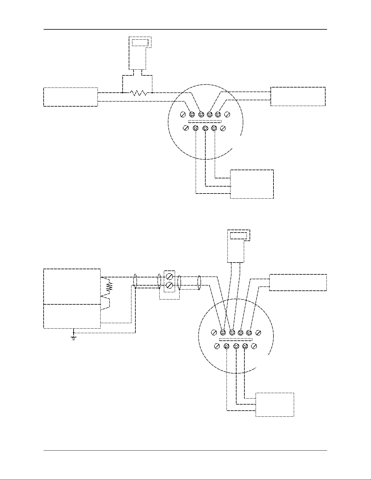
Network for Non-Hazardous Locations
250
See
Note 2
Controller,
Recorder, or Other
1-5 Vdc Device;
See Note 1
System Power
Supply
See
Note 3
MXC
+
_
+
_
250
See
Note 2
See Note 4
Non-Hazardous
Location
Network
Junction
See Note 5
Hazardous
Location
See
Note 3
See Note 6
Signal Test
MXC
_
+
+
Model 344
Terminals
See Note 6
_
Controller,
Recorder, or
Other 1-5 Vdc
Device; Note 1
System Power
Supply
See Note 4
Network for Hazardous Locations
Notes:
1. The System Power Supply is shown separate from the host input device. In practice, it may be part
of the host input device. The host input device can be either a HART or non-HART signaling device,
a Primary Master or a Secondary Master.
2. Network resistance equals the sum of the barrier resistances and the current sense resistor.
Minimum value 250 Ohms; maximum value 1100 Ohms.
3. Connect the MXC (a Secondary Master) to the loop only in the non-hazardous location. The MXC
is a non-polar device.
4. Interconnect all cable shields and ground only at the power source.
+
See Note 5
_
+
_
Supply and
Return Barriers
Shown Above
Signal Test
_ _
+
+
Model 344
Terminals
5. For access to Model 344 terminals, remove shorter end cap.
6. Maximum loop cable length calculated by formula in Section 4.3.5.
X02866S1
September 1995
Page 40

INSTALLATION UM344-2
4-6
6. Maximum loop cable length calculated by formula in Section 4.3.5.
FIGURE 4-1 Point-To-Point Network (Analog Mode)
See
Note 2
MXC
250
See
Note 1
Non-Hazardous
Location
Hazardous
Location
See Note 6
Model 352
Rear
Terminals
See Note 4
Notes:
1. Network resistance equals the sum of the barrier resistances and
the current sense resistor. Minimum value 250 Ohms; maximum value 1100 Ohms.
2. Connect the M XC (a Secondary Master) to the loop only in the non-hazardous location.
The MXC is a non-polar device.
3. Interconnect all cable shields and ground only at the power source.
4. Model 352 Rear Terminal Assignments
A4 - Analog Input 1 (AI1+)
A5 - Analog Input Common (AIC)
B5 - Two-Wire Transmitter Power (+26 Vdc)
AG - Case (Safety) Ground
See Installation And Service Instruction SD352 or User's Manual UM352-1
5. For access to Model 344 terminals, remove enclosure end cap.
A4
A5
B5
AG
See Note 3
Supply and
Return Barriers
Shown Above
Signal Test
_
+
Model 344
Terminals
See Note 5
_
+
X02867S1
FIGURE 4-2 Model 352 SLDC and Model 344 Connections (Analog Mode)
September 1995
Page 41

UM344-2 INSTALLATION
4-7
6. For access to Model 344 terminals, remove enclosure end cap.
See
Note 4
MXC
250
See
Note 2
Non-Hazardous
Location
Hazardous
Location
Network
Primary
Master,
See Note 1
System Power
Supply
Signal Test
_
+
+
+
_
+
_
_
Supply and
Return Barriers
Shown Above
See Note 5
Signal
Test
_
+
+
See Notes 3 and 6
Signal
_
Test
_
_
+
+
Notes:
1. The System Power Supply is shown separate from the host input device. In practice, it may be part
of the host input device. The host input device can either be a HART or non-HART signaling device,
a Primary Master or Secondary Master.
2. Network resistance equals the sum of the barrier resistances and the current sense resistor.
Minimum value 250 Ohms; maximum value 1100 Ohms.
3. A maximum of 15 transmitters may be connected. All must be configured for digital mode.
4. Connect the MXC (a Secondary Master) to the loop only in the non-hazardous location. The MXC is
a non-polar device.
5. Interconnect all cable shields and ground only at the power source.
September 1995
Model 344
Terminal
Model 344
Terminal
FIGURE 4-3 Multi -Drop Network (Digital Mode)
Model 344
Terminal
X02868S1
Page 42

INSTALLATION UM344-2
4-8
Minimum Power Supply Voltage (VDC)
4.3.4 Power Supply Requirements
A power supply is needed to power the Transmitter(s). The power supply can be:
Ÿ A separate stand-alone supply capable of powering several Transmitters. It can be mounted in a
control room or in the field. Follow the power supply manufacturer's recommendations with regard to
mounting and environmental considerations.
Ÿ Located in a controller (such as a Primary Master) or other station able to safely provide additional
operating current and meet the power supply specifications of Section 8.3.2.
Determine needed power supply output voltage by calculating the Network Resistance and consulting
Figure 4-4. It shows the minimum power supply voltage needed for the calculated Network Resistance.
The total Network Resistance is the sum of the Current Sense Resistance, end-to-end Barrier Resistance
(if used), wire resistance, and any other resistances in the loop. The minimum Network Resistance (see
Glossary) required to support HART communications is 250Ω. The maximum resistance is 1100Ω.
1650
1200
1100
1000
800
600
Network Resistance (OHMS)
500
250
OPERATING
REGION
0
10V
12V
17V 20V 24V
30V 34V 40V
42V
X02817S1
45V0
FIGURE 4-4 Supply Voltage Versus Network Resistance
September 1995
Page 43

UM344-2 INSTALLATION
4-9
4.3.4.1 Point-To-Point Network
Figure 4-4 defines an analog mode Transmitter's operating region for the allowable ranges of supply
voltage and network resistance. Perform the following simple calculations to ensure that the power supply
output voltage permits the Transmitter to remain within the indicated operating range.
1. Calculate the minimum power supply output voltage.
The minimum network power supply voltage requirement is a function of Network Resistance and full
scale current (22.5 mA), and is calculated by the following formula:
Minimum Power Supply Output Voltage = 12 volts + (0.0225 x Network Resistance in ohms)
Power supply output voltage must be greater than the calculated value. The minimum voltage across
the input terminals of a Transmitter is 12 volts.
2. Calculate the maximum power supply output voltage.
The maximum network power supply voltage is a function of Network Resistance and zero scale
current (3.85 mA), and is calculated by the following formula:
Maximum Power Supply Output Voltage = 42 volts + (0.00385 x Network Resistance in ohms)
Power supply output voltage must be less than the calculated value. The maximum voltage across the
input terminals of a Transmitter should never exceed 42 volts.
4.3.4.2 Multi-Drop Network
Perform the following simple calculations to ensure that the power supply output voltage permits the
Transmitter to remain within its operating range.
1. Calculate the minimum power supply output voltage.
Minimum network power supply voltage is a function of Network Resistance and the total current
draw of all transmitters in the Network, and is calculated by the following formula:
Minimum Supply Output Voltage = 12 volts + [(0.004 x number of transmitters on Network) x (Network Resistance)]
Power supply output voltage must be greater than the calculated value. The minimum voltage across
the input terminals of a Transmitter is 12 volts.
2. Calculate the maximum power supply output voltage.
Maximum network power supply voltage is a function of Network Resistance and total current draw
of all the transmitters in the Network, and is calculated by the following formula:
Maximum Supply Output Voltage = 42 volts + [(0.004 x number of transmitters on Network) x (Network Resistance)]
September 1995
Page 44

INSTALLATION UM344-2
4-10
Power supply output voltage must be less than the calculated value. The maximum voltage across the
input terminals of a Transmitter should never exceed 42 volts.
The maximum number of Transmitters that can be connected to a Multi-Drop Network is fifteen. Each
Transmitter is "parked" in a low current draw mode (4 mA) to conserve power. Ensure that the network
power supply is capable of sourcing the total current consumed by the number of transmitters on the
Network.
4.3.5 Cable Capacitance and Maximum Length
A cable length calculation is necessary when HART communication is to be employed. Cable
capacitance directly affects maximum Networ k length.
4.3.5.1 Cable Capacitance
Cable type, conductor size, and recommended cable model numbers are stated in Section 8.3.3 Two-Wire
Cable.
Cable capacitance is a parameter used in the calculation of the maximum length of cable that can be used
to construct the Network. The lower the cable capacitance the longer the Network can be.
Manufacturers typically list two capacitance values for an instrumentation cable:
1. Capacitance between the two conductors.
2. Capacitance between one conductor and the other conductor(s) connected to shield. This
capacitance is the worst case value and is to be used in the cable length formula.
4.3.5.2 Maximum Cable Length Calculation
The maximum permissible single-pair cable length is 10,000 feet (3000 meters) or less as determined by
the following formula:
65,000,000 Cf + 10,000
L = -
R x C C
Formula Definitions:
L: The maximum total length of cable permitted to construct the Network. L = Feet when C is in
pF/ft. L = meters when C is in pF/meter.
R: The Network Resistance which is the ohmic sum of the Current Sense Resistance and Barrier
Resistance (both Return and Supply), if any, in the Network and the resistance of the wire.
September 1995
Page 45

UM344-2 INSTALLATION
4-11
C: Cable capacitance per unit length between one conductor and the other conductor connected to
the shield. C may be in pF/ft or pF/meter.
Cf: Total input terminal capacitance of Field Instruments; the Primary Master is excluded. Cf is
given by the following formula:
Cf = (sum of all Cn values) x (5000)
Where Cn is an integer (e.g., 1, 2, 3) corresponding to the input terminal capacitance of a Field
Instrument. Cn values are read from the following table. For Field Instruments without Cn
values, use Cn = 1
FIELD INSTRUMENT CAPACITANCE Cn VALUE
Less than 5000 pF 1
5000 pF to less than 10000 pF 2
10000 pF to less than 15000 pF 3
15000 pF to less than 20000 pF 4
20000 pF to less than 25000 pF 5
25000 pF to less than 30000 pF 6 (Model 344)
Example Calculation:
Assume a Networ k consists of a 344 and a Field Instrument (Cn = 1 and Cn = 6).
Let R = 250Ω, C = 40 pF/ft., Cf = (1 + 6) x 5000 = 35,000
65,000,000 35,000 + 10,000
Then L = - = 5375 feet (1612.5 meters)
(250)(40) 40
4.3.6 Network Junctions
A Network Junction is shown in Figure 4-1. It is a wiring junction installed at a convenient point in the
loop to facilitate wiring, testing, and troubleshooting. Typically the Junction is a conventional terminal block
mounted on a panel with a protective cover, cabinet, or junction box to enclose and protect wiring
terminals.
Multiple Junctions can be installed to provide field access terminals for the connection of an MXC.
Note the following:
Ÿ Network with Barriers - Locate a Junction anywhere along the Network in the non-hazardous area
between a barrier and the Current Sense Resistor.
Ÿ Network without Barriers - A Junction may be located anywhere along the Network between the
Current Sense Resistor and Transmitter.
September 1995
Page 46

INSTALLATION UM344-2
4-12
Ÿ A Junction should be a simple electrical series connection containing NO repeaters or other devices
(active or passive) that can degrade HART communications.
4.3.7 Safety Barriers
Installed safety barriers must comply with the following:
Ÿ Locate intrinsic safety barriers between the system power supply (e.g., Primary Master, if used)
residing in the non-hazardous area and the transmitter(s) in the hazardous area.
Ÿ Combined or separate supply and return barriers may be used.
Ÿ For an intrinsically safe application, the DC voltage applied to the safe side of the barrier must be 0.6
Vdc less than the rated barrier working voltage.
Ÿ An Active Supply Barrier must be operated within its specified input working voltage.
Ÿ Barrier shunt impedance to ground shall not be less than 5000Ω for the HART range of frequencies
(500 Hz to 2500 Hz).
Ÿ Barrier end-to-end resistance, stated by the manufacturer, is used in calculating the maximum
Network cable length and minimum and maximum network voltages.
Ÿ The barrier shall be installed and wired in accordance with the manufacturers instructions.
Refer to Appendix B for hazardous area installation drawings.
4.3.8 Connection of Miscellaneous Hardware
Miscellaneous non-signaling hardware (e.g., recorders, current meters) may be connected to a Point-ToPoint Network in accordance with the following list.
IMPORTANT
No non-signaling hardware (meters or measuring devices) may be
connected to a Multi-Drop Network since the transmitters, in this mode,
do not output an analog process variable.
Ÿ Miscellaneous hardware may be series or parallel connected to the Network according to its function.
Ÿ Miscellaneous hardware must be passive two-terminal devices.
Ÿ Miscellaneous hardware may not generate any type of noise or signals, other than noise that is
inherent in resistive components.
September 1995
Page 47

UM344-2 INSTALLATION
4-13
Ÿ Individual miscellaneous hardware must meet the following requirements:
Ÿ Capacitance to Ground ................ 50 pF maximum
Ÿ Resistance to Ground ................. 1 MΩ minimum
Ÿ Impedance if Series Connected ................ Less than 10Ω
Ÿ Impedance if Parallel Connected .................. Greater than 50kΩ.
Ÿ The maximum number of miscellaneous devices per Network is 16. The combined electrical
characteristics may not exceed the following:
Ÿ Maximum capacitance to ground ................ 800 pF
Ÿ Minimum resistance to ground ................ 62.5kΩ
Ÿ Maximum series impedance ................ 160Ω
Ÿ Minimum parallel impedance ............... 3125Ω
4.3.9 Determine Sensor Cable Requirements
If the Transmitter is mounted remotely from the sensor, the wire characteristics of the extension cable
between the sensor and Transmitter will be different for thermocouple inputs than for RTD, ohm, or
millivolt type inputs.
A. Thermocouple Sensor -to-Transmitter Extension Cable:
1) Select extension grade or thermocouple grade wire of the same calibration as the thermocouple:
calibrations are T, J, E, K, R, S, N, B.
• THERMOCOUPLE GRADE: Wire is made from same materials as thermocouple and
subject to same limits of error as thermocouple.
• EXTENSION GRADE: Noble and refractory thermocouple extension grade wire is made
from inexpensive proprietary alloys that simulate the thermoelectric behavior of the actual
thermocouple element over a limited range of temperatures.
Base metal (T, J, K, E) thermocouple extension grade wire is made from the same materials
as thermocouple wire; however, its use is restricted to a lower range of temperatures.
For extension grade wire, the ambient temperature at the thermocouple head connection point
may not exceed the temperature limits of the extension wire.
2) Cable Recommendation: FEP insulated and jacketed, twisted and shielded. Wire size
should be 16 to 20 AWG.
September 1995
Page 48

INSTALLATION UM344-2
4-14
B. RTD/Ohm Sensor -to-Transmitter Extension Cable
The Transmitter will compensate for the effect of lead wire resistance for 3 and 4-wire RTD's and for
an Ohm (potentiometer) sensor when a 3-wire input connection is used. Input connections may be
made with copper wire.
1) Cable Recommendation for RTD: Multi-conductor high temperature cable, overall braid shield
with three copper TFE insulated conductors and TFE wrapped jacket. Wire size
should be 24 to 16 (AWG).
2) Cable Recommendation for Ohm: Multi-conductor standard temperature instrumentation grade
cable, overall braid shield, PVC insulated three copper conductors with PVC jacket. Wire size
should be 24 to 16 (AWG).
C. Millivolt Sensor -to-Transmitter Extension Cable
Cable Recommendation: Multi-conductor standard temperature instrumentation grade cable, overall
braid shield, PVC insulated twisted pair copper conductors with PVC jacket. Wire size should be 24
to 16 (AWG).
4.3.10 2-Wire RTD Accuracy Limitation
The use of a 2-wire RTD requires a careful analysis of the effects of extension lead wire resistance that
can cause an error in temperature measurement.
A 2-wire RTD may be used when the resistance of the run of lead wire may be considered as an additive
"constant temperature error" and the changes in lead resistance due to ambient temperature changes may
be ignored.
The RTD sensor element is approximately one inch in length. The platinum wire at each end of the RTD
is terminated in insulated copper lead wire. The lead wire extends beyond the sensor probe's protective
metal sheath to a distance specified by the user. The lead wires are terminated in the Transmitter's
terminal compartment when the probe assembly is mounted to the Transmitter. On a remote mounted
Transmitter, the lead wires are termin ated in the probe's connection head and extended by a second set of
wires to the Transmitter.
The extension lead wire resistance is the sum of the resistances of both copper wires connecting the RTD
element to the Transmitter.
Extension lead wire resistances will add to the resistance of the RTD causing a permanent somewhat
higher temperature reading than actually exists at the RTD location. For example, if a 1 degree offset
error is acceptable, then the maximum #24 AWG extension lead wire length permissible would be
calculated for a 100 Ohm RTD (DIN Curve) as follows:
September 1995
Page 49

UM344-2 INSTALLATION
4-15
resistance change of RTD per 1°C
Total length (L) =
resistivity of #24 AWG per foot
0.39 ohms
L = = 14.8 feet or 7.4 feet for each lead.
0.0262 ohms per foot
A 0.3° offset error is caused by an extension lead wire (#24) length of 2.23 feet.
As the calculations indicate, extension lead wire added to a 2-wire RTD can cause serious offset error. A
2-wire RTD should not be used without determining that the result s are acceptable.
The effects of lead wire resistance are compensated for by the Transmitter when 3 and 4-wire RTDs are
used.
4.3.11 Shielding and Grounding
The preferred method of grounding the loop cable shield is illustrated in Figures 4-1, 4-2, and 4-3.
The following guidelines represent proven grounding practices that will reduce magnetically coupled
interference:
Ÿ Ground the cable shield at ONE point, as shown.
Ÿ Preferably, ground the cable shield at the Network power supply.
Ÿ When the cable shield is grounded at the power supply:
a) The cable shield should remain open (not connected) at the Field Instrument (Transmitter).
b) The shields of both cables at a Network Junction should be spliced. Alternatively, connect both
to a terminal in the Box or Panel, provided that the terminal is isolated from ground.
Ÿ Point-To-Point Network
Other permissible single point grounding schemes are:
a) The cable shield may be grounded at the Ground Connection in the signal terminal compartment
of the transmitter's electronic housing. It is recommended that a separate ground wire be run
from this Ground Connection to building ground to ensure a dependable ground.
The power supply (+) and (-) connections must be floated and the shields at Network Junctions
must be connected as discussed above.
September 1995
Page 50

INSTALLATION UM344-2
4-16
b) The cable shield(s) may be grounded at a Network Junction Box or Wiring Panel provided that
the cable shields are connected to either a terminal or the Box or Panel frame, and the terminal
or frame is gr ounded.
The power supply (+) and (-) connections must be floated and the cable shield at the transmitter
must not be connected.
Ÿ Multi -Drop Network
If the Primary Master's power supply output is isolated from ground, the Network may be floated.
The cable shield should be connected only to one point: the Primary Master's negative supply output.
Ÿ Sensor Cable
a) Shielded sensor cable should be used (remote mounted sensor) to minimize the effects of electric
noise. The sensor wires should be twiste d to minimize magnetic induced noise.
b) On a remote mounted thermocouple, if the thermocouple measuring junction is grounded to its
sheath (which is also grounded), connect the sensor cable shield to ground as close as practical to
the measuring junction.
c) On a remote mounted thermocouple, if a thermocouple measuring junction is ungrounded, ground
the cable shield and the negative thermocouple wire to a common point as close as practical to the
measuring junction.
d) Do not connect the cable shield to ground at the Transmitter's terminal compartment if the cable
shield is grounded at the sensor assembly.
4.4 MECHANICAL INSTALLATION
This section describes the mechanical installation of a Transmitter and the installation of electrical conduit
for wiring. Transmitter dimensions are given in Figure 8-3.
Mount a Transmitter in any position (orientation).
Be sure to allow sufficient clearance for:
Ÿ Installation of wiring
Ÿ Removal of the enclosure end caps
Ÿ Viewing of the optional Digital Meter
4.4.1 Pipe Mounting
A Transmitter can be mounted to a vertical or horizontal 2-inch pipe using the supplied mounting bracket.
1. Transmitter to Bracket Mounting
September 1995
Page 51

UM344-2 INSTALLATION
4-17
1) Refer to Figure 4-5 and align four mounting holes in the base of the enclosure with the four 0.281-
inch diameter holes in the Bracket. Note that the transmitter can be mounted to the Bracket in
four possible positions (90° apart) to the Bracket.
2) Using supplied 1/4-20 x 1/2 bolts, mount the transmitter to the bracket.
September 1995
Page 52

INSTALLATION UM344-2
4-18
5.90
(149.9)
2.81
(71.4)
0.72(18.3)
3.80(96.5)
4.04(102.6)
2.81
(71.4)
4.44
(112.8)
.034(8.6)
Diameter
0.61(15.5)
Dimensions in Inches(millimeters)
Mount Transmitter to
bracket with
1/4-20 bolts
and lockwashers,
quantity 4
X02821S1
FIGURE 4-5 Di mensions, Mounting Bracket for Model 344
September 1995
Page 53

UM344-2 INSTALLATION
4-19
X02822S0
Pipe Mounting
Horizontal
4.82(122.4)
5.06(128.5)
OR
Vertical
4.30
(109.2)
Wall Mounting
September 1995
Page 54

INSTALLATION UM344-2
4-20
FIGURE 4-6 Model 344 Mounting Configurations with Supplied Bracket
September 1995
Page 55

UM344-2 INSTALLATION
4-21
2. Bracket to Pipe Mounting
1) At the selected location on the pipe, place the pipe -groove side of the mounting bracket against the
pipe. See Figure 4-6.
2) Slip the supplied U-bolt around the pipe and through one of the two pairs of mounting holes in the
pipe-groove face plate of the bracket.
3) Place a supplied washer and hex nut on each end of the U-bolt and hand tighten the nuts. Rotate
the bracket around the pipe to place the Transmitter in the desired position, then secure the
bracket to the pipe.
3. Reposition the Transmitter's local display (if any) to provide the best possible view of the display.
Refer to Section 4.4.4.
4.4.2 Flat Surface Mounting
A Transmitter can be mounted to a flat surface using the supplied mounting bracket and user supplied
5/16-inch bolts.
Refer to Figures 4-5 and 4-6 and the following for mounting guidance:
1. Bracket To Flat Surface Mountin g
1) Refer to Figure 4-5 for the bracket mounting hole dimensions.
2) Layout the mounting hole pattern on the selected area of the surface. Drill 0.344-inch diameter
mounting holes to accept 5/16-inch bolts.
The thickness of the mounting surface and bracket height above the surface are factors in
determining the required length of the mounting bolts.
3) Place the pipe -groove side of the bracket against the mounting surface site and align the bracket
and surface mounting holes. Install the bracket with user supplied 5/16-inch bolts, washers, and
hex nuts.
2. Transmitter To Bracket Mounting
1) Mount transmitter to bracket as described in Section 4.4.1, step 1.
2) Reposition the Transmitter's local display (if any) to provide the best possible view of the display.
Refer to Section 4.4.4.
September 1995
Page 56

INSTALLATION UM344-2
4-22
4.4.3 Direct Mounting to Process
The Transmitter can be mounted directly to the point of measurement and supported by the thermowell,
extension fittings, and probe assembly.
IMPORTANT
It is recommended that high temperature anti-seize compound be applied
to the threads of thermowells, extension nipples, union connectors, and
sensor assemblies.
Refer to Figures 4-7 and 4-8 and the following for mounting guidance:
1. Unscrew the thermowell from the Sensor Assembly. Refer to the thermowell manufacturer's
installation literature and install the thermowell at the measurement point.
2. Screw onto the thermowell the extension nipple and union (if any).
3. If required, install insulation around the surface area of the measurement point to limit the effects of
heat radiating from the chamber, vessel, or pipe containing the process material.
4. Insert the probe assembly through the extension nipple (if present) and seat into the thermowell.
Screw the probe nipple into the union (if present) or into the thermowell.
5. If it is desired to have terminal compartment access from the same direction as the Sensor Assembly,
then screw an elbow -plus close nipple -plus coupling onto the probe nipple. See Figure 4-7.
6. Select one of the two conduit inlets and route the sensor leads extending from the probe into the
terminal compartment of the transmitter. Do not connect the wires.
7. Screw the transmitter onto the threads of the probe's nipple or elbow fitting (if used).
8. Refer to Section 4.5 to connect the sensor wires to the appropriate terminals.
September 1995
Page 57

UM344-2 INSTALLATION
4-23
WITH DRAIN SEAL
Wall of Pipe
or Process
Vessel
Thermowell
Hex
Thermowell
Wall of Pipe
or Process
Vessel
Union
Extension
Nipple
Insulation
(If Required)
WITHOUT DRAIN SEAL
Thermowell
Hex
Union
Sensor
Hex
Sensor
Hex
Coupling
Conduit for
2-Wire Loop
Wiring
Model 344
Transmitter
X02818S0
Close
Nipple
Elbow
September 1995
Thermowell
Extension
Nipple
Insulation
(If Required)
Conduit
Elbow
Terminal
Compartment
Side
FIGURE 4-7 Transmitter-To-Process Mounting
Model 344
Transmitter
Conduit
for
Wiring
Drain Seal
Page 58

INSTALLATION UM344-2
4-24
2. An RTD probe is a closed end
tube only. RTD sensors are not grounded.
Thermowell
Sensor Probe
Sheath
1/2 NPT Nipple
(Screws into
Transmitter
Conduit Inlet)
Sensor Element
Extension Wires
Extension
Assembly
Sensor
Probe
Probe Hex
RTD or
Thermocouple
Sensor
Element
Thermowell
Hex
Extension
Nipple
1/2 NPT
Thread
Union
Probe
Junction
See Notes
Sheath:
Stainless Steel
or Inconel
X02828S0
Exposed Junction
Notes:
1. Three styles of thermocouple probe junctions are shown.
September 1995
Ungrounded Junction Grounded Junction
FIGURE 4-8 Sensor Assembly
Page 59

UM344-2 INSTALLATION
4-25
4.4.4 Local Digital Meter Installation, Repositioning and Removal
Three procedures are provided in this section. Refer to Figures 4-9 and 4-10 as necessary.
IMPORTANT
Follow proper electronic circuit board handling procedures to avoid
damage to the semiconductors by electrostatic discharge.
• Two procedures describe repositioning of an installed meter: A is for rotating the meter 180°, and B is
for rotating the meter 90° clockwise or counterclockwise (actually ±78°).
• To remove a meter, perform procedure A, steps 1-5 and 9.
• To install a meter perform procedure C.
A. Rotate Meter 180°
1. Turn off power to transmitter and remove enclosure cap to access Digital Display.
2. Snap wrist strap on wrist and connect ground clip to an unpainted area on the Transmitter or
mounting bracket.
3. Locate a short ribbon cable that connects the Electronics Module to the Digital Meter assembly, at
connector J1 typically. Disconnect the connector at the Digital Meter assembly and the slide
cable from cable slot.
4. Loosen (do not remove) upper right and lower left assembly retaining screws.
5. Gently rotate assembly counterclockwise to position upper right retaining screw in large hole in
keyhole and carefully lift assembly clear of screw, then slide it clear of lower left retaining screw.
6. Rotate the assembly 180°, place under the retaining screws, rotate assembly clockwise, and
tighten screws.
7. Position ribbon cable in closest cable slot and connect cable to connector J3.
8. Disconnect wrist strap's ground clip.
9. Replace enclosure cap and restore power to transmitter.
B. Rotate Meter 90° CW or CCW
1. Remove Digital Meter assembly as described in paragraph A, steps 1 to 5, above.
2. Remove the upper right 3.25-inch hex stand-off. Install the stand-off in the upper left mounting
hole.
September 1995
Page 60

INSTALLATION UM344-2
4-26
housing. P1 power connector on Module must engage connector on baseboard.
3. At the Electronics Module, remove the meter mounting bracket attached to the left corner of
bottom circuit board . Install bracket in right front corner of that circuit board.
0 and 180 Digital Meter
Mounting Harware Locations
oo
Meter Orientation
Note 3
o o
90 and 270 Digital Meter
Mounting Hardware Location
Electronics Module
Securing Screw
Connector P2,
for Ribbon Cable
to Digital Meter
Notes:
1. Enclosure Cap and Digital Meter removed to show Meter mounting hardware.
2. Bracket screwed to the Electonics Module.
3. Meter orientations relative to Transmitter body are shown.
4. Jumper W1, Zero and Full Scale Pushbutton Enable/Disable:
Enable - jumper pins 2 & 3
Disable - jumper pins 1 & 2.
Hex Stand-Off
and
Digital Meter Assembly
Mounting Screw
Guide Blocks
Electronics Module
Notes 1 and 5
W1, Note 4
Bracket and
Digital Meter Assembly
Mounting Screw
Note 2
X028AAS0
5. When installing an Electronics Module, guide blocks must engage guide posts in
FIGURE 4-9 Digital Meter Orientation and Mounting Hardware
4. Rotate the Digital Meter assembly either CW or CCW 90° (to the 90° or 270° position), slip the
assembly under the retaining screws, and tighten both screws.
5. Position the cable in the cable slot and insert the cable connector into the closest connector (J2 or
J4).
6. Replace the enclosure cap and restore power to transmitter.
September 1995
Page 61

UM344-2 INSTALLATION
4-27
Factory Meter Orientation 0
Shown with Enclosure Cap Removed
Disconnect
Cable
Notes:
1. Meter can be rotated clockwise or counterclockwise
either 90 (actually, 78 and 282 respectively) or 180 .
2. Remove Enclosure Cap for access to Meter.
3. Move Meter mounting screws when repositioning Meter
90 CW or CCW.
o
o
o o
o
Cable guide
slot (4 places)
Meter Mounting
Screw, qty. 2
Digital LCD Meter
Cable connectors
J1 to J4 wired
in parallel
o
Meter Repositioned 180
Meter Repositioned 90 CCW
o
o
X02870S1
Notes 1, 2 and 3
FIGURE 4-10 Digital Meter Repositioning and Removal
C. Installation
1. Turn off power to transmitter and remove the longer enclosure cap.
2. Snap wrist strap on wrist and connect ground clip to an unpainted area on the Transmitter or
mounting bracket.
September 1995
Page 62

INSTALLATION UM344-2
4-28
3. Determine desired meter orientation and perform either procedure A or B. Note the following
when installing and positioning the short ribbon cable and when applying power to the transmitter.
NOTE
Pin 1 end of cable connector is identified by dark Red or Blue striped cable
conductor. Pin 1 of Board “J” connector is identified by the “1” printed
next to one corner of the connector.
At power-up, an automatic display test is performed which turns on all
LCD segments for approximately 5 seconds. At the conclusion of the
test, if the Transmitter is active, a numerical value will be displayed with
an annunciator. If the Transmitter is configured as a Controller,
additional annunciators may be displayed.
4.4.5 Electrical Conduit and Cable Installation
Electrical conduit and network, sensor, and power wire are supplied by the user. Access to electrical
terminals is described in Section 4.4.5.3.
For conduit and cable routing, refer to the user's installation drawings. Installation of conduit and cabling
should follow the guidelines given below.
4.4.5.1 Conduit
Ÿ Transmitter conduit inlets accept male conduit fittings. Refer to the Transmitter's nameplate and
Section 8.1 to determine whether conduit threads are ½-14 NPT or M20 x 1.5.
Seal ½ NPT fittings with TFE/PTFE tape; seal M20 fittings with a soft-setting sealing compound rated for
at least 105°C (221°F).
Ÿ When routing conduit, avoid areas that might subject the conduit to chemical or physical abuse or
areas with high EMI/RFI conditions.
Ÿ Long sensor cable runs should be installed in conduit between the transmitter and sensor.
Ÿ Install sensor cable in conduit in areas of high electrical interference.
Ÿ Install conduit for field wiring.
Ÿ If a high humidity environment can exist and the transmitter is located at a low point in the conduit run,
install drain seals at the transmitter's conduit inlets to prevent condensation from entering the
Transmitter. See Figure 4-11.
Ÿ Remove all sharp edges or burrs from conduit that may damage wires.
September 1995
Page 63

UM344-2 INSTALLATION
4-29
Explosion Proof Installation
Plug unused
entrance
Conduit
for field
wiring
(DC power)
Drain Seal
Conduit Drain Installation
For explosion proof installation use conduit
seal, Crouse-Hinds type EYS or equivalent,
on wiring outlet.
Plug unused
Entrance
Conduit for field
wiring (DC power)
X02824S1
FIGURE 4-11 Conduit Drain and Explosion Proof Installations
September 1995
Page 64

INSTALLATION UM344-2
4-30
Ÿ Thermocouple wire must be handled with great care when being installed in conduit. Decalibration of
the wire can result by cold -working the metal conductor, an effect that can occur when the wire is drawn
through a conduit or damaged by rough handling or vibration.
4.4.5.2 Cables
Ÿ Mark or tag each signal cable conductor as either SIGNAL (+) or SIGNAL (-) to ensure correct
connection at the Transmitter.
Ÿ Mark or tag each sensor wire to be connected to a remote mounted transmitter to indicate its specific
transmitter terminal number (1, 2, 3) connection
EXAMPLE: 3-wire RTD tag descriptors: RTD (+) #1, RTDI #2, RTD (-) #3
Thermocouple tag descriptor: TC (+) #1, TC (-) #3
Ÿ Use pulling grips and cable lubricants for easier cable pulling. Pull cable through conduit into
Transmitter terminal compartment.
Ÿ Do not exceed the maximum permitted pulling tension on the cables. Ma ximum tension is normally
specified as 40% of the cable's breaking strength.
Ÿ Do not exceed the maximum conduit fill specified by the National Electric Code.
4.4.5.3 Access to Transmitter Terminal Compartment
Two terminal strips for signal (loop), MXC, test (milliammeter), and sensor connections are located inside
the shorter enclosure cap; see Figure 1-1. To access the terminal strips, simply unscrew the enclosure
cap protecting the terminal compartment.
This completes the mechanical installation.
September 1995
Page 65

UM344-2 INSTALLATION
4-31
4.5 ELECTRICAL INSTALLATION
This section describes loop wiring for Point-To-Point and Multi-Drop Networks. Refer also to Section 4.6
for installations in hazardous locations. Figure 4-12 shows signal and sensor termination terminal strips in
the Transmitter’s enclosure.
The following should already have been completed:
Ÿ Selection of either analog or digital operating mode and corresponding Point-To-Point or Multi-Drop
Network; Section 4.3.3.
Ÿ Selection of a power supply; Section 4.3.4.
Ÿ Mechanical installation of Transmitter(s) installed; Section 4.4.
Ÿ Pulling of loop and sensor cables through conduit and into terminal compartment; Section 4.4.5.
Connect the transmitter to the loop as follows.
1. Access transmitter signal terminals by unscrewing the short enclosure cap.
2. As shown in Figure 4-12, there are two terminal strips:
Upper Terminal Strip
• SIGNAL (+) and SIGNAL (-): Transmitter Network Connections
• TEST (+) and TEST (-): Analog test (milliammeter) connections
Lower Terminal Strip
• #1: RTD (+) or OHM (+); TC (+) or mV (+) sensor connections
• #2: RTDI sensor connection
• #3: RTD (-) or OHM (-); TC (-) or mV (-) sensor connections
3. Determine method of connection to transmitter signal (loop) terminals.
Strip loop cable and conductors. Install ring tongue or spring spade terminals for #6 screws and the
cable conductor gauge. If terminals will not be used, tin conductor ends and form a loop.
September 1995
Page 66

INSTALLATION UM344-2
4-32
X02869S1
MXC
Connections
Signal (+)
Terminal
Signal (-)
Terminal
Test (+)
Terminal
TESTSIGNAL
+ -
Test (-)
Terminal
Ground
Screw
Notes:
1. Viewed with enclosure cap
removed.
2. MXC = Moore XTC
Communicator.
Sensor Terminals for
Thermocouple, RTD,
Ohms,or mV Input
FIGURE 4-12 Signal (Loop) , Sensor, MXC and Test Terminals
4. Connect the loop cable to the SIGNAL (+) and (-) terminals inside the Transmitter's enclosure. Refer
to Figure 4-1, 4-2 or 4-3 for the needed connections for the type of Network. Terminals will
accommodate wire sizes up to 16 AWG. Attached to both signal terminals are lugs that facilitate the
connection of the MXC Communicator. DO NOT connect signal wires to the lugs.
IMPORTANT
The cable shield must be insulated from all terminals and the transmitter
enclosure. Refer to Section 4.3.11 for additiona l shielding and grounding
information.
5. Connect Sensor Wires
Hook each stripped solid wire end or insert each crimp-on terminal under the appropriate terminal
screw and tighten the screw for a reliable electrical connection. Refer to figures showing the needed
connections as listed below in paragraphs 1) to 4).
1) RTD Sensor - Connect the tagged RTD leads as shown in Figure 4-13 detail A, B, or C,
depending upon type of RTD used.
2) Thermocouple Sensor - Connect the tagged thermocouple extension leads as shown in Figure 4-13
detail D. The positive and negative thermocouple leads are usually color coded.
September 1995
Page 67

UM344-2 INSTALLATION
4-33
Ground shields only at the power source
.
Signal
Cable
Note 1
RTD+ RTD-
Note 2
No connection
RTD-RTD+
A. 2-Wire RTD
Signal
cable
Note 2
Note 2
RTDI
RTD+
Signal
Cable
RTD-
Note 2
No connection
RTD-RTD+
B. 3-Wire RTD
Signal
cable
Note 2
Note 2
RTDI
RTD+
C. 4-Wire RTD
RTDI
Signal
Cable
Note 2
RTD-
Note 2
No connection
RTD-RTD+
No connection
Signal
cable
Note 2
TC+ TC-
Note 2
No connection
TC+
TC-
D. Thermocouple
Notes:
1. Install jumper wire between terminals 1 and 2.
2. Connect the sensor and signal cable shields and insulate from ground.
September 1995
OHM+
OHM-
mV+ mV-
Note 2
No connection
OHMI
OHM+ OHM-
Jumper
OHMI
mV+ mV-
E. OHMS Input
FIGURE 4-13 Model 344 Sensor Wiring
+ -
mV
F. mV Input
Note 2
No connection
X02825S1
Page 68

INSTALLATION UM344-2
4-34
Standard ANSI color coding is used on insulated thermocouple or extension grade wire when the
insulation permits. Some insulations will use a colored tracer to indicate the lead polarity. Refer
to Table 4.2 for color code information and bare wire characteristics for identifying non-color
coded wires.
When connecting solid thermocouple extension wire, wire insulation should butt against the head
of the screw. The conductor should not be visible.
TABLE 4.2 Thermocouple And Extension Grade Wire Characteristics
ANSI TYPE POSITIVE LEAD NEGATIVE LEAD BARE WIRE
T/C METAL COLOR METAL COLOR CHARACTERISTICS
T Copper Blue Constantan Red Copper - yellow
Constantan - silver
J Iron White Constantan Red Iron - magnetic
Constantan - nonmagnetic
E Chromel Purple Constantan Red Chromel - shiny metal
Constantan - dull metal
K Chromel Yellow Alumel Red Chromel - non-magnetic
Alumel - magnetic
S Platinum & 10%
Rhodium
R Platinum & 13%
Rhodium
B Platinum & 30%
Rhodium
Black Pure Platinum Red ---
Black Pure Platinum Red ---
Gray Platinum with 0.6%
Rhodium
Red ---
3) Ohms-to-Milliampere Conversion - connect the OHM (+), OHM (-), and OHM I leads as shown
in Figure 4-13 detail E, Ohms Input.
4) Millivolt-to-Milliampere Conversion - Connect the mV (+) and mV (-) leads as shown in Figure 413 detail F, mV Input.
Inspect each connection for strands of wire that could short to an adjacent terminal, for connection to
correct terminal, and for tightness of terminal screw.
Be certain that the shield braid is insulated from all terminals and the metal terminal enclosure.
6. Reinstall enclosure cap. Tighten cap to compress the internal O-ring.
IMPORTANT
Be certain that enclosure threads are coated with an anti-seize compound and
that the cap seal (O-ring) is in place before installing a cap. A typical compound
is Never-Seez by Emhart Bostik.
September 1995
Page 69

UM344-2 INSTALLATION
4-35
7. If one of the two electrical conduit entrances in the housing is not used, it should be plugged. Refer to
the Transmitter's nameplate and Section 8.1 to determine whether entrance holes accept ½-14 NPT
or M20 x 1.5 fittings.
Seal ½ NPT fittings with TFE/PTFE tape; seal M20 fittings with a soft setting sealing compound rated for
at least 105°C (221°F).
4.6 HAZARDOUS AREA INSTALLATION
Drawings showing Transmitter installation data for hazardous areas are located in Appendix B. Entity
parameters, barrier selection, and important wiring information are specified on these drawings. The
Appendix also contains a list of tested barriers.
Before installing a transmitter in a hazardous area, check the nameplate and Sections 8.1 and 8.3 of this
Manual for required approvals or certifications.
NOTE
The MXC is approved for use in non-hazardous areas only.
EXPLOSION-PROOF INSTALLATION
If the installation is required to be explosion-proof per the National Electrical Code, refer to a current copy
of the Code and the follow ing:
Ÿ User supplied explosion-proof conduit seals (glands) are required on transmitter housing conduit outlets
and any installed junction boxes. See Figure 4-11.
Ÿ Explosion-proof glands must provide a good seal. Apply a sealing compound around the sealing
surface if necessary.
Ÿ Sensor and power wiring conduit entries at the Transmitter must have a minimum of five threads fully
engaged.
Ÿ The enclosure cap must be installed and have a minimum of eight threads fully engaged with no
damaged threads pe rmitted.
Ÿ Go to Section 4.5 for wiring connections to the transmitter's terminals. Refer to Appendix B for
hazardous area installation information.
This completes the physical installation.
•
September 1995
Page 70

INSTALLATION UM344-2
4-36
September 1995
Page 71

UM344-2 ON-LINE AND OFF-LINE OPERATION
5-1
5.0 ON-LINE AND OFF-LINE OPERATION
On-line operation is any configuration or monitoring activity which involves direct communication with a
transmitter. When the controller function block is disabled, the local pushbuttons may be used to configure
range and damping. When the controller is enabled, the local pushbuttons may be used to display
PROCESS VARIABLE (PV), SETPOINT (SP) and VALVE (V); transfer control mode from AUTO
(A) to MANUAL (M); and change or store SET POINT and VALVE settings.
The configuration may be edited remotely using an MXC, a personal computer (PC) running XTC
Configuration Software, or another HART Primary or Secondary Master. The MXC can also be used to
monitor a transmitter’s variables and to look at a transmitter’s status.
Off-line operation is any configuration activity that occurs without direct communication with a transmitter.
This includes using the MXC to create or edit a configuration and then to store that configuration in an
MXC archive. It also includes using a personal computer and XTC Configuration Software to create or
edit, and then store, a configuration.
5.1 ON-LINE OPERATION
The first part of this section contains the steps to configure and monitor a Model 344 from an MXC. The
latter part of this section describes configuring the transmitter using the local pushbuttons.
5.1.1 Using the MXC for Configuration
Each transmitter is shipped with default data stored in its memory. Some of this data controls communication and transmitter operation and cannot be altered by the user. Other data determines how the
transmitter responds to changes in temperature with a change in current or digital output and is alterable
by the user. Using the MXC in the on-line mode, configurations can be uploaded from the transmitter,
edited, and saved to archive memory or downloaded to the Model 344. The following sections describe
configuration in more detail.
The following sections are in a two column format. Step-by-step procedures are in the right column. The
left column contains relevant MXC screens.
September 1995
Page 72

ON-LINE AND OFF-LINE OPERATION UM344-2
5-2
OVRD
Dev ID: 210300003C
Tag: TTC-101 ADD: 00
LOOP CAL/ CON -
TEST FIG
END
CONFIGURATION MODE
EDIT EDIT
ARCH CONF END
TEMP XMTR
MODEL 344
TYPE 03
QUIT CONT
WRITE PROTECT STATUS
DISABLE
LAST NEXT SEL/ SEL/
OPTN OPTN END CONT
CONFIGURATION
COMPLETE
RE- DOWN
QUIT SAVE VIEW LOAD
SELECT BLOCK TO EDIT
- SENSOR INPUT SELPREV NEXT END ECT
1. Establish communication with a transmitter; see Section 3.2.
The On-Line Menu shown adjacent should be displayed.
2. Press CONFIG (F3) at the On-Line Menu screen to enter
the configuration mode and display the Configuration Mode
screen (adjacent). This screen is used to select editing a
configuration stored in either the selected transmitter or
archived in the MXC.
3. Press EDIT CONF (F2) to continue with configuration and
display the transmitter type. See adjacent screen.
NOTE
The EDIT ARCH (F1) key is pressed to edit an
archived configuration and will be discussed later.
4. Press CONT (F4) to show the Status screen. Select the
state of the Write Protect mode (enable /disable) by toggling
the LAST OPTN (F1) or NEXT OPTN ( F2) key.
NOTE
Write Protect prevents changes to transmitter
parameters and the transmitter will not accept a
downloaded configuration.
5. Press SEL/CONT to continue. The MXC screen will display
the Function Block menu.
Press SEL/END (F3) to end this session. The MXC screen
will display the Configuration Complete menu with options to
quit configuration mode, save the configuration, review the
configuration, or download the configuration
. NOTE
Most configuration screens show the option of
ending configuration and going to this screen.
These choices are discussed in Section 5.1.1.9.
6. Choose the function block to be configured. Press either
PREV (F1) or NEXT (F2) to scroll through the function
blocks.
September 1995
Page 73

UM344-2 ON-LINE AND OFF-LINE OPERATION
5-3
NOTE
Function blocks are in an easy to use format with
configuration parameters grouped by like
function. Those supported are Sensor Input,
Operator Display, Transmitter ID, Output Block,
Alarm Block, SP Track & Hold, A/M Transfer
and Controller Block. Each is shown in
Appendix A.
7. Press SELECT (F4) to view or edit a function block’s
parameters. Pressing END (F3) will end configuration (see
step 4 above).
Go to the section for the selected function block (Sections 5.1.1.1
- 5.1.1.8).
5.1.1.1 Sensor Input Block
The following parameters can be changed: INPUT TYPE,
MEASURED VARIABLE (MV) UNITS, RANGE,
DAMPING, and BURNOUT DIRECTION.
INPUT TYPE: T/C
J THERMOCOUPLE
LAST NEXT
OPTN OPTN CONTEND
SEL/
MEASURED VARIBLE
UNITS: deg F
LAST
OPTN OPTN CONTEND
NEXT
SEL/
SEL/
SEL/
1. Press SEL (F4) at the Sensor Input Block to display the Input
Type.
2. Press LAST OPTN (F1) or NEXT OPTN (F2) to scroll
through the Input Options: T/C, OHM, mV, RTD.
3. Press SEL/CONT (F4) to select the current parameter, and
continue to the next Input Type configuration parameter.
4. Press LAST OPTN (F1) or NEXT OPTN (F2) to scroll
RANGE LO: 0.0000
deg F HI: 100.00
SNSR
SEL/
SEL/
CONTENDEDIT INPUT
through the Input Options.
5. Press SEL/CONT (F4) to select the current parameter, and
continue to the MEASURED VARIABLE UNITS Screen.
6. Press LAST OPTN (F1) or NEXT OPTN (F2) to scroll
through the units selections. These units are listed in
Appendix C under the Sensor Input Block description.
7. Press SEL/CONT (F4) to select the current parameter,
display the Range screen, and continue to the next
configuration parameter (go to step 8).
Pressing SEL/END (F3) will select the current parameter, end
configuration, and return to the On-Line Menu.
August 1995
Page 74

ON-LINE AND OFF-LINE OPERATION UM344-2
5-4
8. The Range screen shows the unit of measurement and the
lower and upper range values (LRV and URV) currently
configured. Set the transmitter's temperature range
corresponding to 4 and 20 mA. (See Section 8 for
transmitter input ranges.)
These values can be changed using either of two methods:
"Tell" or "Show."
Values for URV and LRV entered in the following
procedures are stored in the MXC. Complete config uration and perform the download steps in Section 5.1.2
to send the configuration to a transmitter.
METHOD 1 - The "Tell"
MV LO : 0.0000
ENTER MV LO:
EN < QUIT TER
Method
MV HI : 100.00
ENTER MV HI:
EN < QUIT TER
1) Press EDIT (F1) to display the screen for entering the
Lower Range Value (LRV).
2) Type the desired value at the blinking cursor.
3) Press either ENTER (F4) to select the value or QUIT
(F3) to exit this selection without saving.
4) The next screen displays the transmitter's Upper Range
Value (URV) which is set as described above.
METHOD 2 - The "Show"
Method
In this method, the transmitter is ranged by applyin g actual URV
mV: 79.120 deg F
-0.0000 TO 100.00
SET
LO
SET
HI
QUIT ENTER
and LRV sensor inputs.
1) Press SNSR INPT (F2) in the Range screen.
The screen displays the On-Line value for the actual
temperature or MV units that the transmitter is reading.
2) Apply the LRV sensor input to the transmitter.
3) Press SET LO (F1) to set the LRV for the transmitter's
range.
4) Apply the URV sensor input to the transmitter
5) Press SET HI (F2) to set the URV for the transmitter's
range. The screen shows new LRV and URV values.
September 1995
Page 75

UM344-2 ON-LINE AND OFF-LINE OPERATION
5-5
DAMPING : 1.0000 SEC
SEL/ SEL/
EDIT END CONT
DAMPING : SEC
ENTER DAMPING VALUE
EN < QUIT TER
BURNOUT DIRECTION:
UPSCALE
LAST
OPTN
NEXT
OPTN
SEL/
END
SEL/
CONT
5.1.1.2 Operator Display Block
SELECT BLOCK TO EDIT
- OPERATOR DISPLAY SELPREV NEXT END ECT
PROCESS VARIABLE
UNITS:
EGF
SEL/
END
SEL/
CONT< >
RANGE LO: 0.0000
HI: 100.00
EDIT
SEL/
END
SEL/
CONT
Press ENTER to store the new value in the on-line
alterable memory and return to the Range screen.
Pressing QUIT displays the Range screen without saving
a new value.
NOTE
To conserve battery power, the MXC should not
be left in the Sensor Input mode.
9. At the Range screen, press SEL/CONT to display the
Damping screen and current damping value.
Press EDIT (F1) to enter a new damping value.
Type a new damping value and press either ENTER to save
and exit or QUIT to exit without saving.
10. At the Burnout Direction screen press either LAST OPTN
or NEXT OPTN to choose UPSCALE or DOWNSCALE.
When the desired function is chosen, press SEL/END to
return to the Function Block Menu.
Go to the next section or the next desired function block.
The Operator Display block has the following parameters:
PROCESS VARIABLE UNITS, RANGE, AUTO RERANGE,
and LOCAL DISPLAY CODE.
1. Press SELECT to edit process variable units.
2. Type the process variable's units. It can be a combination of
up to four alphanumeric characters. To edit, use the < or >
keys to move to the character to be changed.
Press SEL/CONT to continue. Press SEL/END to end
configuration of this block and return to the Function Block
Menu.
3. To set the range in the Operator Display Block, use the "tell"
method described in Section 5.1.1.1 Sensor Input Block. Edit
PV LO and HI in their respective screens by typing the
upper and lower range values desired.
Press SEL/CONT to continue. Pressing SEL/END will end
configuration and return to the Function Block Menu.
August 1995
Page 76

ON-LINE AND OFF-LINE OPERATION UM344-2
5-6
< > END CONT
AUTO RERANGE:
DISABLE
LAST NEXT SEL/ SEL/
OPTN OPTN END CONT
LOCAL DISPLAY CODE:
PROCESS VARIABLE
LAST NEXT SEL/ SEL/
OPTN OPTN END CONT
5.1.1.3 Transmitter ID Block
SELECT BLOCK TO EDIT
- TRANSMITTER ID SELPREV NEXT END ECT
TAG: TC-101
SEL/ SEL/
DATE (DD/MM/YY):
28/02/95
SEL/ SEL/
< > END CONT
DEVICE SERIAL NUMBER
12345678
SEL/ SEL/
< > END CONT
4. Set Auto Rerange to enable or disable using the LAST
OPTN and NEXT OPTN keys.
Press SEL/CONT to continue. Pressing SEL/END will end
configuration of this block.
5. Scroll through the Local Display Code using the LAST
OPTN and NEXT OPTN keys to view the following three
choices: MEASURED VARIABLE, PERCENT, or
PROCESS VARIABLE. Display the desired selection.
Press either SEL/END or SEL/CONT to enter the selection
and return to the Function Block Menu.
Go to the next section or the desired function block.
1. Press the NEXT key to display the Transmitter ID Block and
then press SELECT to display the Tag screen.
2. If desired, enter or edit the transmitter tagname by typing an
alphanumeric sequence. The blinking cursor shows where a
character will be placed. Use the arrow keys < and > to
move the cursor to any position in the tagname.
Press SEL/CONT to continue. Pressing SEL/END will end
configuration of the transmitter ID Block.
3. As described in steps 1 and 2, enter or edit the
DESCRIPTOR and the MESSAGE, respectively.
4. At the Date screen, enter or edit the date using the < and >
keys to move the cursor to any position in the date field.
NOTE
The format shown on the screen, DD/MM/YY,
must be followed or the MXC will not download
the selection.
Press SEL/CONT to display the Device Serial Number
screen. Pressing SEL/END will end configuration of the
transmitter ID Block.
5. Enter or edit the device serial number on the nameplate using
the < and > keys to place the cursor to any position within the
serial number field.
September 1995
Page 77

UM344-2 ON-LINE AND OFF-LINE OPERATION
5-7
EDIT END CONT
SHORT ADDRESS 00
SEL/ SEL/
SHORT ADDRESS 00
ENTER ADDRESS
EN < QUIT TER
5.1.1.4 Output Block
FAILSAFE LEVEL :
LOW
LAST NEXT SEL/ SEL/
OPTN OPTN END CONT
5.1.1.5 Alarm Block
ALARM1 : ENABLE
LAST NEXT
OPTN OPTN
SEL/
END
SEL/
CONT
ALARM1 SETPOINT:
25.000 DEG F
SEL/
EDIT
SEL/
CONTEND
NOTE
Only numbers may be used in the serial number
field.
Press SEL/CONT to display the Short Address screen.
Pressing SEL/END will end configuration of the transmitter
ID Block.
6. Enter or edit the transmitter short address using the EDIT,
QUIT, and ENTER keys as described below.
EDIT - display the Short Address edit screen. Use the < key
to edit by erasing one character in the address at a time,
starting with the last character. Type the new short address
on the keypad.
QUIT - return to the previous screen without saving the
address.
ENTER - store the new short address in the current MXC
On-Line Memory. The MXC will now show the Function
Block Menu.
1. At the Function Block Menu, press NEXT to configure the
Output block and display the Failsafe Level screen.
2. Edit or change this value by scrolling through the selections
using the LAST OPTN and NEXT OPTN keys.
3. Press either SEL/END or SEL/CONT to return to the
Function Block Menu.
There are two absolute alarms which may be configured as HI or
LO. The setpoint for the alarms is in the same units selected in
the operator display block.
1. Press SEL (F4) at the Alarm Block to display the Alarm 1
screen.
2. Press NEXT OPTN (F2) to enable or disable Alarm 1.
3. Press SEL/CONT (F4) to continue to the setpoint screen.
August 1995
Page 78

ON-LINE AND OFF-LINE OPERATION UM344-2
5-8
4. Press EDIT (F1) to edit the
setpoint value. Press ENTER
(F4) to change the setpoint
value. Press QUIT (F3) to exit
without changing the setpoint.
September 1995
Page 79

UM344-2 ON-LINE AND OFF-LINE OPERATION
5-9
SELF CLEARING NAKS:
ON
LAST
OPTN OPTN CONTEND
NEXT
SEL/
SEL/
ALARMS OUT OF
SERVICE: OFF
LAST
OPTN
NEXT
OPTN
SEL/
END
SEL/
CONT
5.1.1.6 Setpoint Track and Hold
Block
TRACKING SETPOINT:
NO
LAST
OPTN
NEXT
OPTN
SEL/
END
SEL/
CONT
PUSP: 55.000 DEG F
0.0000 TO 100.00
SEL/
CONT
EDIT
SEL/
END
5.1.1.7 A/M Transfer Block
POWER-UP MODE:
AUTOMATIC
LAST
OPTN
NEXT
OPTN
SEL/
END
SEL/
CONT
AUTOMATIC MODE ONLY:
NO
LAST
OPTN
NEXT
OPTN
SEL/
END
SEL/
CONT
5. Press SEL/CONT (F4) to configure the alarm type.
6. Press NEXT OPTN (F2) to choose either HIGH or LOW.
7. Press SEL/CONT (F4) to configure Alarm 2 or SEL/END
(F3) to return to the Function Block Menu.
8. At the SELF CLEARING NAKS screen press NEXT
OPTN (F2) to choose ON or OFF.
9. At the ALARMS OUT OF SERVICE screen press NEXT
OPTN (F2) to choose OFF or ON and SEL/CONT (F4) to
return to the Function Block Menu.
This function block can be configured as tracking or nontracking. When configured as tracking, the SP will track the PV
when the controller is in manual. If it is configured as nontracking the SP will remain at its hold value. On power -up, the
operating value in the function block is initialized to the Power-Up
(PUSP) value.
1. At the SP TRACK & HOLD menu press SELECT (F4) to
configure the TRACKING SETPOINT block. Press NEXT
OPTN (F2) to choose either YES or NO. Press SEL/CONT
(F4) to continue to the PUSP screen.
2. At the PUSP screen Press EDIT (F1) to edit the setpoint.
Press ENTER (F4) to change the setpoint or QUIT (F3) to
exit without changing the setpoint. Press SEL/CONT (F4) to
return to the Function Block Menu.
The A/M Transfer may be configured to power-up in Automatic
or Manual. From the A/M Transfer Menu choose SELECT (F4)
for the POWER-UP MODE screen.
1. Press NEXT OPTN (F2) to choose between AUTOMATIC
AND MANUAL. Press SEL/CONT (F4) for the
AUTOMATIC MODE ONLY screen.
2. Press NEXT OPTN (F2) to choose YES or NO. When
YES is selected the function block will always remain in the
AUTO position. Press SEL/CONT (F4) for the POWERUP VALVE screen.
August 1995
Page 80

ON-LINE AND OFF-LINE OPERATION UM344-2
5-10
POWER-UP VALVE:
0.000%
SEL/
CONT
EDIT
SEL/
END
5.1.1.8 Controller Block
CONTROLLER: ON
LAST
OPTN
NEXT
OPTN
SEL/
END
SEL/
CONT
CONTROLLER TYPE: PID
LAST
OPTN
ACTION: REVERSE
LAST
OPTN
PROPORTIONAL GAIN:
1.0000
EDIT
MANUAL RESET TRACK:
NO
LAST
OPTN
NEXT
OPTN
NEXT
OPTN
NEXT
OPTN
SEL/
END
SEL/
END
SEL/
END
SEL/
END
SEL/
CONT
SEL/
CONT
SEL/
CONT
SEL/
CONT
5.1.1.9 End or Review
Configuration
3. Press EDIT (F1) to edit the Power-Up Valve setting. Press
ENTER (F4) to change the setting, press QUIT (F3) to exit
without changing the setting. Press SEL/CONT (F4) to
return to the Function Block menu.
The controller function block provides an extensive range of
Proportional-Integral-Derivative functions including PID, PD and
ID. For more detailed descriptions of these controller functions
refer to the appendix.
1. At the CONTROLLER BLOCK Screen press SELECT
(F4) .
2. Press NEXT OPTN (F2) to turn the controller function ON
or OFF.
3. Press SEL/CONT (F4) to configure the Controller
Parameters or SEL/END (F3) to return to the Function
Block menu.
4. At the CONTROLLER TYPE screen use LAST OPTN
(F1) and NEXT OPTN (F2) to scroll through the PID, PD,
ID options. Press SEL/CONT (F4) for the controller
ACTION screen.
5. Press NEXT OPTN (F2) to select either a DIRECT or
REVERSE acting controller. Press SEL/CONT (F4) to
continue to the Proportional Gain, Time -Integral, Time
Derivative, Derivative Gain, and Manual Reset blocks.
6. Press EDIT (F1) to edit a parameter. Press ENTER (F4) to
change a parameter or QUIT (F3) to exit without changing
the parameter.
7. Press SEL/CONT (F4) for the MANUAL RESET TRACK
screen. Press NEXT OPTN (F2) to select YES or NO.
8. Press SEL/CONT (F4) to return to the Function Block
Menu. This completes configuration.
September 1995
Page 81

UM344-2 ON-LINE AND OFF-LINE OPERATION
5-11
As described in the previous
sections, there is a Function Block
Menu in configuration mode from
which basic function blocks can be
accessed. Also in the previous
sections, it was explained how to get
back to this screen when making
changes to a function block.
SELECT BLOCK TO EDIT
- SENSOR INPUT SELPREV NEXT END ECT
August 1995
Page 82

ON-LINE AND OFF-LINE OPERATION UM344-2
5-12
OVRD
1. Choose END at the Function Block Menu in configuration
CONFIGURATION
COMPLETE
RE- DOWN
QUIT SAVE VIEW LOAD
Dev ID: 210300003C
Tag: TTC-101 ADD: 00
LOOP CAL/ CON -
TEST FIG
END
mode to display the Configuration Complete Menu. It shows
these selections: QUIT, SAVE, REVIEW, or
DOWNLOAD. Choose one after all configuration changes
are entered.
QUIT - return to the MXC's On-Line Menu (adjacent) that
appeared after initial communication had been established.
SAVE - go to the Save To Archive screen to save the
transmitter configuration in an archive. The MXC will show
the tagname, the archive location last used in the MXC, and
SAVE TO ARCHIVE 92
TTC-101
NEW
YES ARCH END
three selections: YES, NEW ARCH, and END.
YES - save the configuration in the archive location
shown on the screen. If the archive shown contains a
CAUTION - PRESSING
ENTER WILL REPLACE
ARCH 00 A- ENPTC - 101 BORT TER
NEW ARCH - save the configuration to a new archive
END - return to the previous screen without saving.
configuration (other than a default configuration), a
Caution screen will be displayed. Press Enter to
overwrite the stored configuration.
location.
REVIEW - return to the Function Block Menu. The
configuration can be reentered and edited from this Menu by
pressing CONT.
TEMP XMTR
MODEL 344
TYPE 03
DOWNLOAD - downloads the configuration to the
transmitter. Go to the next section.
QUIT CONT
5.1.2 Downloading A
Configuration
After all configuration information has been edited at the MXC,
download the configuration to the transmitter. A download can
be performed in configuration mode at any time by pressing a
series of END and SEL/END keys until a DOWNLOAD key is
NO CONFIGURATION
CHANGES MADE.
DOWNLOAD ABORTED.
CONT
visible on the screen.
1. Press DOWNLOAD to send the configuration to the
transmitter.
WARNING! DOWNLOADING
WILL CHANGE XMTR
CONFIG- A- DOWN
URATION BORT LOAD
Ÿ If no changes have been made to a configuration and
DOWNLOAD is pressed, the MXC will display the
adjacent screen and will not perform a download to
prevent unnecessary communication.
September 1995
Page 83

UM344-2 ON-LINE AND OFF-LINE OPERATION
5-13
Ÿ If the configuration has been
edited, the MXC will display
the adjacent warning that
the transmitter's
configuration will be
changed.
August 1995
Page 84

ON-LINE AND OFF-LINE OPERATION UM344-2
5-14
DOWNLOADING
CONFIGURATION
- PLEASE WAIT -
DOWNLOAD
COMPLETE
5.1.3 Local Transmitter
Operation
2. From the above Warning screen, press one of the following
two keys:
DOWNLOAD - start a download. The MXC will show the
Download Wait screen and then the Download Complete
screen. The new configuration is now stored in the
transmitter.
ABORT - return to the pr evious screen.
The Model 344 has two local pushbuttons labeled FS (Fullscale)
and Z (Zero) located on the housing. These are used to set
range and damping when the controller block is configured
“OFF”. This is detailed in the following sections.
When the controller block is configured “ON” the ranging/
damping capabilities are not available. In this mode the
pushbuttons may be used to transfer between AUTO and
MANUAL control, change VALVE output, and change the
SETPOINT. This is detailed in the following sections.
Local Pushbutton Operation:
The “Pushbutton Mode” must be activated as described below to
use the Zero and Full Scale pushbuttons.
• The Pushbutton Mode is activated whenever either
pushbutton is pressed and held for a minimum of 5 seconds
and then released. The “PB” annunciator on the Digital
Meter will be lit while the Pushbutton Mode is active.
• The Pushbutton mode will automatically time -out after 1
minute.
• Failure to hold a pushbutton ON for a minimum of 5 seconds
will prevent entry into the Pushbutton mode.
• The pushbuttons are disabled when the transmitter is placed
in “CONFIGURATION HOLD,” as when downloading a
configuration.
Pushbuttons are enabled or disabled by jumper W1 on the
Electronics Module and are enabled by the factory. Jumpering
pins 2 and 3 equals ENABLE. When the jumper is in the
DISABLE position, the pushbuttons perform no function.
September 1995
Page 85

UM344-2 ON-LINE AND OFF-LINE OPERATION
5-15
Status
Variable
5.1.3.1 Display Functions The numerals displayed on the Digital Meter represent the value
of the PROCESS VARIABLE (PV) when the “PV”
annunciator is lit; see Figure 5-1. The units associated with PV
are chosen during transmitter configuration of the OPERATOR
DISPLAY BLOCK. Refer to section 5.1.1.2. There are three
OUTPUT DISPLAY CODE choices listed in Table 5.1 that
describe what information is displayed and how it will be
annunciated.
The VALVE (V) is always displayed as a percentage of
controller output and the “V” and “%” annunciators will be lit.
The SETPOINT (SP) is displayed in the same units as the
PROCESS VARIABLE (PV). When the controller is ON
depressing the FULL SCALE pushbutton will toggle the display
between “PV” and “V”. The ZERO pushbutton will toggle the
display between “PV” and “SP”.
PB
Status
Alarm
Status
Display
Code
PV
Displayed
Variable
Indicator
SP
V
A M
Auto/Manual
PB AL % ENG
Displayed
FIGURE 5-1 Model 344 Digital Meter
TABLE 5.1 Output Display Code Choices
OUTPUT DISPLAY
LIT ANNUN. PV UNITS
CODE
0 (Percent) % Percent of full span (0 to 100)
1 (Process Variable) ENG Engineering Units (e.g., CEL, FAHR)
2 (Measured Variable) None CEL, OHMS, MV, KELV, RANK, FAHR
August 1995
Page 86

ON-LINE AND OFF-LINE OPERATION UM344-2
5-16
September 1995
Page 87

UM344-2 ON-LINE AND OFF-LINE OPERATION
5-17
5.1.3.2 Local Pushbutton Input
Ranging (Controller OFF)
The low and high process temperatures selected as the 0%
and 100% span points may be applied to the transmitter and
stored in the EEPROM using the ZERO/FULLSCALE
pushbuttons. This procedure assumes the transmitter is field
mounted to an operating process. If the transmitter does not
contain an optional Digital Meter to report the process
variable, other instrumentation on the Network must be
available to provide this in formation.
1. Open the sliding cover on top of the Transmitter's
housing to access the ZERO/FS pushbuttons. See Figure
1-1.
2. Change ZERO range value:
1) Supply new ZERO value.
If the process variable currently being reported by
the Transmitter is not the desired ZERO value, then
the process must be manipulated by an operator to
arrive at the desired value.
2) Activate the Pushbutton Mode
Press and hold for 5 seconds or more the ZERO
pushbutton, then release the pushbutton
3) Enter ZERO Valu e
Press and release the Zero pushbutton. The new
0% range value is stored in memory. If an optional
Digital Meter is installed, observe that the "PB"
annunciator in the display extinguishes (Normal
Mode).
When a new 0% value is set, the Transmitters 100%
value is automatically shifted to maintain the original
span except as follows:
• If the process is out of range, no new ZERO
value is stored.
• If the new ZERO value would shift the
FULLSCALE value past the sensor limit, the
new FULLSCALE value is automatically set
to the appropriate sensor limit (except in the
case where this would produce a span that is
August 1995
Page 88

ON-LINE AND OFF-LINE OPERATION UM344-2
5-18
too small, in which case
no new ZERO or
FULLSCALE value is
stored).
3. Change FULLSCALE range value:
1) Supply FULLSCALE value.
If the process variable currently being reported by
the Transmitter is not the desired FULLSCALE
value, then the process must be manipulated by an
operator to arrive at the desired value.
2) Activate the Pushbutton Mode
Press and hold for 5 seconds or more the
FULLSCALE pushbutton, then release the
pushbutton.
3) Enter FULLSCALE value
Press and release the FULLSCALE pushbutton. The new
100% range value is stored in memory. If an optional Digital
Meter is installed, observe that the "PB" annunciator in the
display extinguishes (Normal Mode).
NOTE
Changing the FULLSCALE range value
does not affect the ZERO range value.
If the input value is beyond the sensor
limit, or the span is too small, no new
FULLSCALE range value will be stored
4. If a damping value change is not required, return the
protective cover over the pushbuttons.
September 1995
Page 89

UM344-2 ON-LINE AND OFF-LINE OPERATION
5-19
5.1.3.3 Local Pushbutton
Damping Adjustment (Controller
OFF)
Adjusting the damping changes the value of the digital filter’s
time constant. An installed Digital Meter is recommended
for this procedure so that the damping values may be
monitored.
1. Activate the Pushbutton Damping Mode.
Simultaneously press and hold, for 5 seconds or more, the
FULLSCALE and ZERO pushbuttons, then release both
pushbuttons. Note the following.
• The Damping Mode is automatically de -activated
when a 1 minute "mode active" period times-out. If
a change is not made, the present value is retained.
• When both pushbuttons are pressed a "PB"
annunciator will appear on the Digital Meter. If the
pushbuttons have been held on for the required
minimum 5 seconds, when they are released, the
"PB" annunciator will remain on and the Digital
Meter will alternately display the letters "SEC" (for
seconds) and the present damping value in seconds.
2. Select a new damping value. The damping value choices
are: 0, 0.5, 1, 2, 5, 10, 20, 30, 60, 90, and 120 seconds.
Repeatedly press the ZERO pushbutton to step down or
the FULLSCALE pushbutton to step up through the list.
Select a time constant from the list that is closest to the
desired value.
3. Simultaneously press, then release, both pushbuttons. The
new value is stored in memory and normal operation is
restored.
4. Restore protective cover over pushbuttons.
5. To set damping without a digital meter activate the
pushbutton mode as described in step 1 above.
6. Repeatedly press the ZERO pushbutton at least ten times
to set the damping value to zero seconds.
August 1995
Page 90

ON-LINE AND OFF-LINE OPERATION UM344-2
5-20
7. Refer to step 2 above and select the new damping value.
Count the number of steps (damping values) from “0”
seconds to the selected value. This number “N” will be
used in the following step 8.
8. Press and release the FULLSCALE pushbutton “N”
times to step to the selected damping value.
9. Perform steps 3 and 4 above.
5.1.3.4 Local Pushbutton
AUTO/MANUAL, SETPOINT and
VALVE Adjustments (Controller
ON)
These procedures assume the Transmitter-Controller is field
mounted to an operating process and contains an optional
Digital Meter to display the AUTO or MANUAL control
mode and PROCESS VARIABLE, SET POINT, and
VALVE values.
Open the sliding cover on top of the Transmitter's housing to
access the ZERO/FULLSCALE pushbuttons (Figure 1-1),
then refer to the following procedures to make any required
changes to the Controller's operation.
A. Change AUTO/MANUAL Control Mode
The active control mode is shown by a lit "A" (AUTO)
or "M" (MANUAL).
IMPORTANT
If the present control mode is AUTO, and
the Controller's A/M TRANSFER BLOCK
has been configured for "AUTOMATIC
MODE ONLY", a change from AUTO to
MANUAL cannot be made using the
pushbuttons.
1. Note the present control mode as indicated in the
Digital Meter. Simultaneously press and hold, for a
minimum of 5 seconds, the ZERO/FULLSCALE
pushbuttons, then release both buttons.
2. Confirm the transfer of mode control from "A" to
"M" or "M" to "A".
September 1995
Page 91

UM344-2 ON-LINE AND OFF-LINE OPERATION
5-21
B. Change SET POINT
1. The Controller must be in the AUTO control mode to
change the SET POINT; if not, place the Controller
in the AUTO control mode.
2. Press and hold, for a minimum of 5 seconds, the
ZERO pushbutton, then release the button.
The "SP" and "PB" annunciators shall be lit and the
"PV" annunciator shall be extinguished.
The displayed number is the active SET POINT
value.
3. Select new SET POINT. Note the following.
• Cycling (pressing and releasing in less than 1
second) the ZERO or FULLSCALE pushbutton
respectively decrements or increments the SET
POINT in 0.01% increments of span.
• Pressing and holding either pushbutton, for more
than 1 second, initiates a special acceleration
algorithm whereby the SET POINT changes in
greater and greater increments until limiting
occurs.
• The new SET POINT value is changed in RAM
only and not yet stored permanently in memory.
If the Pushbutton Mode times-out before
storage is accomplished, the Controller will
operate with the new SET POINT; however, the
new value will be lost after a power-down or
Master Reset.
C. Store New SET POINT to Memory (new Power-Up
Setpoint Valve in Setpoint Track & Hold Block)
1. Simultaneously press and release both pushbuttons to
store new SET POINT.
After SET POINT storage, the Controller exits the
Pushbutton Mode and returns to normal operation.
D. Change VALVE
August 1995
Page 92

ON-LINE AND OFF-LINE OPERATION UM344-2
5-22
1. The Controller must be in the
MANUAL control mode to
change the VALVE; if it is not,
place the Controller in the
MANUAL control mode.
September 1995
Page 93

UM344-2 ON-LINE AND OFF-LINE OPERATION
5-23
2. Press and hold, for a minimum of 5 seconds, the
FULLSCALE pushbutton, then release the button.
Note the following.
• The "V", "%", and "PB" annunciators shall be lit
and the "PV" annunciator shall be extinguished.
• The displayed number is the VALVE position in
percent (-1 to 110).
• Interpreting a VALVE Open/Close position
depends upon knowing if the FINAL
CONTROL ELEMENT is configured as
REVERSE or DIRECT acting. For DIRECT
acting, 0% indicates a fully closed valve and
100% indicates a fully opened valve. The
opposite is true for a REVERSE acting
controller.
3. Select new VALVE between -1.0% and 110%.
Note the following.
• Cycling (pressing and releasing in less than 1
second) the ZERO or FULLSCALE pushbutton
respectively decrements or increments the
VALVE in 0.01 % increments.
• Pressing and holding either pushbutton, for more
than 1 second, initiates a special acceleration
mode whereby the VALVE changes in greater
and greater increments until limiting occurs.
• The new value is changed in RAM only and not
yet stored permanently in memory. If the
Pushbutton Mode times-out before storage is
accomplished, the Controller will operate with
the new VALVE; however, the new value will
be lost after a power-down or Master Reset.
E. Store New VALVE to Memory (new Power-Up Valve
in Auto Manual Transfer Block)
1. Simultaneously press and release both pushbuttons to
store new VALVE.
After VALVE storage, the Controller exits the
Pushbutton Mode and returns to normal operation.
August 1995
Page 94

ON-LINE AND OFF-LINE OPERATION UM344-2
5-24
OVRD
EXIT
5.1.4 Quick Access Key
Operation
Dev ID: 210300003C
Tag: TTC-101 ADD: 00
LOOP CAL/ CON -
TEST FIG
M: 76.534 deg F
I: 3.8377 mA
P: 63.272 deg F
TREND WHICH VAR?
MEASURED VARIABLE
SELPREV NEXT END ECT
ENTER SAMPLING TIME
SECONDS
EN < END TER
WARNING: TREND TIME
MUST FALL BETWEEN
1 AND 300 SECONDS.
END
END
MXC Quick Access keys are used to view transmitter
parameters while the MXC is on-line and communicating with a
transmitter (refer to Section 2). Eight Quick Access keys are
used with the Model 344: TRANS. VAR'S., TREND, ZOOM,
and STATUS, are available with the controller ON or OFF.
CHANGE SP, CHANGE VALVE, A/M and TUNE are only
available when the controller is ON. Press a key to access live
transmitter data.
NOTE
Conserve battery power. Do not leave the MXC
in the on-line mode.
1. Establish communication with a transmitter, see Section 3.2,
and go to the On-Line Menu (adjacent).
2. Press a Quick Access key to view the desired transmitter
parameter(s) at the On-Line Menu. The following
paragraphs will describe how to view these parameters.
TRANS. VAR'S. - displays updated on-line transmitter
parameters. These parameters include the measured
variable (MV), the current output (I), the process variable
(PV) and their respective units or the Process (P), Set Point
(S) and Valve (V) controller variables.. Exit this screen by
again pressing the TRANS. VAR'S. key or pressing END.
TREND - displays the adjacent screen to select the variable
to be trended.
1) Press PREV or NEXT to toggle between Process
Variable, Measured Variable, and Valve with the
Controller “ON.”
2) Press SELECT to enter a value. Pressing END will exit
this procedure and display the On-Line Menu.
3) Type the desired sample time: range 1-300 seconds;
default is 1 second. Thirteen samples (maximum) of the
variable can be shown while sampling at the sample time
chosen.
If the sample time entered is greater than 300 seconds, a
Warning message will appear that shows the range of
values.
September 1995
Page 95

UM344-2 ON-LINE AND OFF-LINE OPERATION
5-25
EXIT
400.00
105.24
F4=EXIT
-20.005
ENTER ZOOM VALUE
EN < END TER
122.01
105.24
F4=EXIT
84.005
MODEL NUMBER
344 BN5N1G
SOFTWARE REV 01
S/N EXIT
TTC-101 AUTOMATIC
CONT END
SENSOR S/N: 0009C1
4) Press ENTER. The following are shown in the adjacent
screen: Upper and Lower Range Values stored in the
transmitter, the current transmitter reading and the
thirteen sample trend.
5) Press either TREND or F4 to exit this screen.
ZOOM - expands a portion of a selected variable's trend. Zoom
is selected from the Trend screen.
1) Press ZOOM to display the adjacent screen. Type a
zoom value.
If the value is outside the transmitter's range, a Caution
screen will appear with a selection to show the range of
possible values.
The MXC will display the trended variable within the
zoom range chosen (i.e. zoom range = 10% of the
transmitter range, centered on the zoom value entered)
on the screen. The screen will show:
- Upper and Lower Range Values of zoomed range
- current transmitter reading
- trend of thirteen samples
2) Press either F4 to exit to the Trend screen or ZOOM to
return to the Enter Zoom Value screen.
3) Press EXIT in the Trend screen to go to the On-Line
Menu.
STATUS - displays the transmitter’s tagname and existing
status’s. See adjacent screen.
1) Press CONT to display the transmitter's model number,
and software revision number. Pressing EXIT will end
this display.
2) Press S/N to show the sensor serial number. Pressing
EXIT will return to the Status screen.
3) Press EXIT twice to go to the On-Line Menu.
August 1995
Page 96

ON-LINE AND OFF-LINE OPERATION UM344-2
5-26
S: 50.000%
NEW SETPOINT:
0.0000 TO 100.00
<
END
ENTER
VALVE: 10.000%
NEW VALVE:
-1.000 TO 110.00
<
END
ENTER
STATUS: AUTOMATIC
MANUAL
PV 47.625
SP 47.625
V 56.000
ACTION REVERSE CONT
PV 99.930
SP 99.930
V 50.210
PG TI TD CONT
PV 23.000
SP 47.000
V 10.000
DG MR END CONT
AUTO
END
CHANGE SP - allows you to view and change the on-linesetpoint of the controller.
1) Enter new setpoint and press ENTER (F4) to store the
value.
2) Press the “CHANGE SP” key again or END (F3) to
exit.
CHANGE VALVE - allows you to view and change the position
of the valve in MANUAL. If the controller is in AUTO, the
valve cannot be changed.
1) Enter the new valve setting and press ENTER (F4) to
store the new value.
2) Press the “CHANGE VALVE” key again or END (F3)
to exit.
A/M - toggles the controller between automatic and manual
control
1) Press MANUAL (F1) or AUTO (F2) to change state.
2) Press “A/M” key again, or END (F4) to exit.
TUNE - displays controller tuning parameters for viewing or
editing.
1) The first screen displays the Process, Setpoint, and
Valve settings and the controller action. Press CONT
(F4) to continue.
2) The Proportional Gain (PG), Time Integral (TI) and Time
Derivative (TD) can be changed from this screen. Press
F1, F2, or F3 to display the current value and edit the
parameter.
3) Press CONT (F4) to continue.
4) The Derivative Gain (DG) and Manual Reset (MR) can
be changed from this screen. Press F1 or F2 to display
the current value and edit the parameter.
5) Press CONT (F4) to go to the previous screen. Press
the “TUNE” key again, or END (F3) to exit.
September 1995
Page 97

UM344-2 ON-LINE AND OFF-LINE OPERATION
5-27
5.2 OFF-LINE OPERATION Off-line operations include editing parameters in a transmitter
configuration stored in an MXC archive for downloading at a
later time to a transmitter. The first part of this section describes
off-line configuration editing. The second part explains
downloading a configuration to a transmitter.
An archive is a transmitter configuration stored in the MXC. It
resides in a specific location in the MXC's On-Line Memory.
This Memory can store up to 100 configurations, numbered 0-99.
To save time and reduce errors, simply recall and edit an
archived configuration rather than creating a completely new
configuration.
Configurati ons created using the MXTC Configuration Software
(PN 15939-41Vn.nn*) running on a personal computer can be
downloaded to and archived in the MXC.
* Vn.nn is the software version number.
5.2.1 Using Off-Line
Operations to Access an
Archive
SELECT FUNCTION
FIND ARCH TEST
XMIT FUNC MXC END
ENTER ARCHIVE # (0-99)
OR TAG:
EN < > END TER
WARNING : ARCHIVE
CONTAINS NO DATA
A BORT CONT
1. At the Main Menu, press ARCH FUNC to go to the Enter
Archive # screen (Off-Line Archive menu).
2. To call an archived configuration, type the archive number or
the tagname of a transmitter and press ENTER.
To create a new configuration to be archived, type an unused
archive number (0-99) and press ENTER.
3. Select one of the following:
Ÿ If there is no data stored in this archive, a Warning
screen appears. Press ABORT to exit the archive
function or press CONT to continue. Go to step 4.
ARCHIVE 97 FTC1300
SELECT A FUNCTION
EDIT CLR
ARCH ARCH END
Ÿ If the configuration at this archive number is no longer
needed, press CLR ARCH to erase it. Press END to
exit this screen.
Ÿ To review or edit the configuration, press EDIT ARCH.
Press CONT and select a function block to view or edit,
then return to this section and go to "After configuration
is complete." step 1.
August 1995
Page 98

ON-LINE AND OFF-LINE OPERATION UM344-2
5-28
SELECT X-MITTER TYPE
TEMP CONTROLLER
PREV
NEXT
END
SELECT
ARCHIVE 97 DEFAULT
SELECT A FUNCTION
EDIT
ARCH END
CONFIGURATION
COMPLETE
REQUIT SAVE VIEW
SAVE TO ARCHIVE 97
DEFAULT
NEW
YES ARCH END
ERROR! ARCHIVE TYPE
DOESN'T MATCH THE
TRANSMITTER TYPE
CONT
WARNING: TAG NAME
USED ENTER NEW TAG
NAME.
CONT
4. Use PREV and NEXT to select the transmitter type Temperature - then press SELECT. The default configur ation for a temperature transmitter will be loaded into the
Off-Line Memory of the MXC.
5. The next screen shows the archive number to be edited.
Press either EDIT ARCH to begin editing or END to select
another archive number.
6. Press CONT to continue and select a configuration block for
editing. Refer to Section 5.1.1 to edit configuration
parameters.
Press QUIT to return to the previous screen.
After configuration is complete:
1. Press END in the Function Block menu to access the
following three choices from the adjacent screen.
QUIT - go to the Main Menu and end configuration.
REVIEW - return to the Function Block menu to make any
changes or additions. Refer to Section 5.1.1 as necessary.
SAVE - show the archive number and tagname of the
current configuration and provide the option to save the
configuration either under the current archive number or
under a new number. Go to step 2.
2. Press YES in the Save Archive screen to save the archive
under the current number. Perform one of the two steps
below:
Ÿ If the new configuration will overwrite an existing
archive, the MXC will provide a warning me ssage before
the store operation is performed. Press ENTER to
continue.
Ÿ If the tagname of a new configuration has already been
assigned to an archived configuration, a WARNING
screen appears. Press CONT to move to the TRANSMITTER ID block and display the tag selection.
- If the tagname is not to be changed, press either
SEL/END to return to the Save Archive screen or
SEL/CONT to return to the previous screen.
September 1995
Page 99

UM344-2 ON-LINE AND OFF-LINE OPERATION
5-29
- If the tagname is changed, press SEL/END or
SEL/CONT to return to the original Save screen.
Follow the prompts to save the configuration in the
MXC.
5.2.2 Using an Archive in OnLine Memory
CONFIGURATION MODE
An archived configuration can be accessed using the MXC
during On-Line operations through the configuration mode.
1. Press CONFIG at the On-Line menu screen to display:
EDIT EDIT
ARCH CONF END
ENTER ARCHIVE # (0-99)
OR TAG:
EN < > END TER
EDIT ARCH, EDIT CONF, and END.
2. Select EDIT ARCH to call an archived configuration from
MXC memory.
3. At the adjacent screen, type the archive number or the
tagname of the configuration to be edited and press ENTER.
ARCHIVE 97 DEFAULT
SELECT A FUNCTION
EDIT
ARCH END
Ÿ If the archive contains data, the next screen will provide
the option of editing the archive or downloading the
archive directly to the transmitter.
WARNING : ARCHIVE
CONTAINS NO DATA
A BORT CONT
Ÿ If the archive contains no data, a Warning message will
appear and default configuration data will be loaded into
the On-Line memory. Press CONT to edit or download
the configuration.
ERROR! ARCHIVE TYPE
DOESN'T MATCH THE
TRANSMITTER TYPE
CONT
Ÿ If the archive contains data that does not match the
current transmitter type, an Error message will appear.
Press CONT to choose a new archive number.
4. Press either EDIT ARCH to edit the configuration as
described in section 5.1.1 or DOWNLOAD to download the
configuration to the transmitter and bring up a series of
screens.
When download is chosen, the MXC will display:
Ÿ A prompt if there are any differences between the
downloaded configuration data and the configuration
August 1995
Page 100

ON-LINE AND OFF-LINE OPERATION UM344-2
5-30
resident in the transmitter simply respond to the
prompt, continue or abort.
September 1995
 Loading...