

Page 1

Preface,Contents
SIMATICHMI
TouchPanelTP170A,TP170B
OperatorPanelOP170B
EquipmentManual
Introduction
Functionality
Commissioning
OperatingTouchPanels
TP170AandTP170B
OperatingKeyboardUnit
OP170B
ScreenObjectsforTP170A
ScreenObjectsforTP170Band
OP170B
RecipesforTP170Band
OP170B
SystemSettings
1
2
3
4
5
6
7
8
9
6AV6591 -- 1DC11 -- 1AB0
Installation
UnitDescription
MemoryCardsfor
TP170BandOP170B
Maintenance/Upkeep
OperatingSystemUpdate
APPENDICES
Glossary,Index
10
11
12
13
14
A
E
Release07/00
Page 2

SafetyGuidelines
Thismanualcontainsnoticeswhichyoushouldobservetoensureyourownpersonalsafety,aswellasto
protecttheproductandconnectedequipment.Thesenoticesarehighlightedinthemanualbyawarning
triangleandaremarkedasfollowsaccordingtothelevelofdanger:
Warning
!
indicatesthatdeath,severepersonalinjuryorsubstantialpropertydamagecanresultifproperprecautionsarenottaken.
Caution
!
indicatesthatminorpersonalinjuryorpropertydamagecanresultifproperprecautionsarenottaken.
Note
drawsyourattentiontoparticularlyimportantinformationontheproduct,handlingtheproduct,ortoa
particularpartofthedocumentation.
QualifiedPersonnel
Equipmentmaybecommissionedandoperatedonlybyqualifiedpersonnel.Qualifiedpersonnelwithin
themeaningofthesafetynoticesinthismanualarepersonswhoareauthorizedtocommission,ground
andidentifyequipment,systemsandcircuitsinaccordancewithsafetyengineeringstandards.
CorrectUsage
!
Trademarks
Impressum
Notethefollowing:
Warning
TheequipmentmaybeusedonlyfortheapplicationsstipulatedinthecatalogandinthetechnicaldescriptionandonlyinconjunctionwithotherequipmentandcomponentsrecommendedorapprovedbySiemens.
Startupmustnottakeplaceuntilitisestablishedthatthemachine,whichistoaccommodatethiscomponent,isinconformitywiththeguideline89/392/EEC.
Faultlessandsafeoperationoftheproductpresupposespropertransportation,properstorage,erection
andinstallationaswellascarefuloperationandmaintenance.
TheregisteredtrademarksofSiemensAGarelistedinthePreface.
Someoftheotherdesignationsusedinthesedocumentsarealsoregisteredtrademarks;theowner’s
rightsmaybeviolatediftheyareusedbethirdpartiesfortheirownpurposes.
EditorandPublisher:A&DPT1.
DisclaimerofLiabilityCopyrightSiemensAG2000Allrightsreserved
Thereproduction,transmissionoruseofthisdocumentoritscontentsisnot
permittedwithoutexpresswrittenauthority.Offenderswillbeliablefor
damages.Allrights,includingrightscreatedbypatentgrantorregistrationof
anutilitymodelordesign,arereserved.
SiemensAG
Automation&Drives
SIMATICHumanMachineInterface
Postfach4848,D-90327Nuernberg
Index-2
SiemensAktiengesellschaft Orderno:6AV6591--1DC11--1AB0
Wehavecheckedthecontentsofthismanualforagreementwiththehardwareandsoftwaredescribed.Sincedeviationscannotbeprecludedentirely,
wecannotguaranteefullagreement.However,thedatainthismanualare
reviewedregularlyandanynecessarycorrectionsincludedinsubsequent
editions.Suggestionsforimprovementarewelcomed.
ESiemensAG2000
Technicaldatasubjecttochange.
TP170A,TP170B,OP170BEquipmentManual
Release07/00
Page 3

Preface
This manual
The TP170 A, TP170 B, OP170 B equipment manual is part of the SIMATIC HMI
documentation. It provides operation, installation, configuration and maintenance
personnel with information concerning installation, functionality, operation and
technical design of the SIMATIC operating units TP170 A, TP170 B and OP170 B.
An overview of the entire SIMATIC HMI documentation is provided in Appendix E.
Organization of the manual
The manual is organized into the following chapters:
Chapter Contents
1-2 Overview of the features and functional scope of the unit
3-7 Commissioning and operation
8 Recipes for TP170 B and OP170 B
9 System settings
10 - 13 Mechanical and electrical installation, unit description, retrofitting of
options as well as maintenance and upkeep.
14 Informationen on updating the operating system.
Appendix S Technical Data
S Interface Assignments
S System Messages
S ESD Guidelines
S SIMATIC HMI Documentation
TP170 A, TP 170 B, OP170 B Equipment Manual
Release 07/00
i
Page 4

Preface
Conventions
The following cionventions are used throughout this manual:
Motor off Text in the operating unit display is presented in this
Tag Symbolic names representing tag values on the screen are
Screens Functions available for selection are presented in this italic
ESC The names of keys and buttons are displayed in a different
History
The various releases of this manual correspond to the following versions of the
ProTool CS configuration software:
typewriter font.
presented in this italic typewriter font.
font.
font.
Trademarks
Edition Comment ProTool Version
12/99 First release of the TP170 A equipment
From V5.2
manual
07/00 Extensions to the TP170 B and OP170 B
From V5.2 + SP2
units
The following names are registered trademarks of the Siemens AG:
S SIMATICR
S SIMATIC HMIR
S HMIR
S ProToolR
S ProTool/LiteR
S ProTool/ProR
S SIMATIC Multi PanelR
S SIMATIC Multifunctional PlatformR
S MP 270R
S ProAgentR
ii
TP170 A, TP 170 B, OP170 B Equipment Manual
Release 07/00
Page 5

Other support
In the case of technical queries, please contact the Siemens representatives in the
subsidiaries and branches responsible for your area.
SIMATIC Customer Support Hotline
Available worldwide, at all times:
Johnson City
Preface
Nuernberg
Singapur
SIMATIC Basic Hotline
Nuernberg Johnson City
Singapur
SIMATIC BASIC Hotline SIMATIC BASIC Hotline SIMATIC BASIC Hotline
Local time Mo - Fr 7:00 to 17:00 Local time Mo - Fr 8:00 to 19:00 Local time Mo - Fr 8:30 to 17:30
Telephone: +49 (911) 895-7000 Telephone:
Fax: +49 (911) 895-7002 Fax:
E-Mail: simatic.support@
nbgm.siemens.de
E-Mail:
+1 423 461-2522 Telephone: +65 740-7000
+1 423 461-2231 Fax: +65 740-7001
simatic.hotline@
sea.siemens.com
E-Mail: simatic.hotline@
sae.siemens.com.sg
SIMATIC Premium Hotline
(charged, only with SIMATIC Card)
Time: Mo - Fr 0:00 to 24:00
Telephone: +49 (911) 895-7777
Fax: +49 (911) 895-7001
TP170 A, TP 170 B, OP170 B Equipment Manual
Release 07/00
iii
Page 6

Preface
SIMATIC Customer Online Services
SIMATIC Customer Support offers comprehensive additional information
concerning SIMATIC products through its Online services as follows:
S Up-to-date general information is provided
-- i n Internet under http://www.ad.siemens.de/simatic
-- v i a t h e Fax-Polling under 08765-93 02 77 95 00
S Up-to-date product information and downloads for practical use can be found:
-- i n Internet under http://www.ad.siemens.de/support/html-00/
Abbreviations
The abbreviations used in this user’s guide have the following meaning:
AG (PLC) Programmable Logic Controller
AM Alarm Message
ANSI American National Standards Institute
AS 511 Protocol of the PU interface to SIMATIC S5
ASCII American Standard Code for Information Interchange
CCFL Cold Cathode Fluorescence Lamp
CF Compact Flash
CPU Central Processing Unit
CSV Comma Separated Values
DP Decentralized Periphery
DRAM Dynamic Random Access Memory
DSN Data Source Name
ESD Electrostatically Sensitive Device
EM Event Message
EMC Electromagnetic compatibility
HMI Human Machine Interface
IF Interface
LCD Liquid Crystal Display
LED Light Emitting Diode
MP Multi Panel
MPI Multipoint Interface (SIMATIC S7)
OP Operator Panel
PC Personal Computer
PCL Printer Control Language
PLC Programmable Logic Controller
iv
TP170 A, TP 170 B, OP170 B Equipment Manual
Release 07/00
Page 7

Preface
PU Programming Unit
PPI Point to Point Interface (SIMATIC S7)
RAM Random Access Memory
SRAM Static Random Access Memory
STN Super Twisted Nematic
TCP/IP Transmission Control Protocol/Internet Protocol
TFT Thin Film Transistor
TTL Transistor--Transistor Logic
TP Touch Panel
A list of all the specialist terms together with their explanations is provided in the
Glossary at the end of this guide.
TP170 A, TP 170 B, OP170 B Equipment Manual
Release 07/00
v
Page 8

Preface
vi
TP170 A, TP 170 B, OP170 B Equipment Manual
Release 07/00
Page 9

Contents
1 Introduction 1-1............................................................
2 Functionality 2-1...........................................................
3 Commissioning 3-1........................................................
3.1 Initial Startup 3-3...................................................
3.2 Recommissioning 3-4...............................................
3.3 Options for Download Mode 3-6......................................
3.4 Testing a Project on the Operating Unit 3-10.............................
3.5 Download Back (TP170 B and OP170 B) 3-12...........................
3.6 Backup/Restore the Internal Flash Memory
(TP170 B and OP170 B) 3-14.........................................
4 Operating Touch Panels TP170 A and TP170 B 4-1...........................
4.1 Operating Touch Elements 4-1........................................
4.1.1 Enter Numeric Values 4-3............................................
4.1.2 Enter Alphanumeric Values 4-5.......................................
4.1.3 Enter Symbolic Values on the TP170 B 4-7.............................
4.2 Calling in Help Text on the TP170 B 4-8................................
5 Operating Keyboard Unit OP170 B 5-1.......................................
5.1 Integrated Keyboard 5-1.............................................
5.2 Key Combinations 5-5...............................................
5.3 Entering Values 5-7.................................................
5.3.1 Enter Numeric Values 5-8............................................
5.3.2 Enter Alphanumeric Values 5-9.......................................
5.3.3 Enter Symbolic Values 5-10...........................................
5.4 Call Help Text 5-11...................................................
TP170 A, TP 170 B, OP170 B Equipment Manual
Release 07/00
vii
Page 10

Contents
6 Screen Objects for TP170 A 6-1.............................................
6.1 General Operation 6-2...............................................
6.1.1 Operating Screens 6-2..............................................
6.1.2 Logging On and Off from the Operating Unit 6-3........................
6.2 Overview of Screen Objects 6-4......................................
6.3 Input Field for Date/Time 6-5.........................................
6.4 Input Field for Confidential Password Entry 6-5.........................
6.5 Status Button 6-6...................................................
6.6 Messages 6-7......................................................
6.7 Bar graphs 6-9.....................................................
7 Screen Objects for TP170 B and OP170 B 7-1................................
7.1 General Operation 7-2...............................................
7.1.1 Operating screens 7-2...............................................
7.1.2 Logging On and Off from the Operating Unit 7-5........................
7.2 Overview of Screen Objects 7-6......................................
7.3 Input Field for Date/Time 7-9.........................................
7.4 Input Field for Confidential Password Entry 7-9.........................
7.5 Buttons 7-10........................................................
7.6 Status Button 7-11...................................................
7.7 Switch 7-13.........................................................
7.8 Messages 7-14......................................................
7.8.1 ALARM_S 7-16......................................................
7.8.2 Message Line 7-17...................................................
7.8.3 Message Window 7-17...............................................
7.8.4 Message Page 7-19..................................................
7.8.5 Message Buffer 7-20.................................................
7.8.6 Message View 7-21..................................................
7.8.7 Simple Message View 7-23...........................................
7.9 Bar Graphs 7-24.....................................................
7.10 Trend View 7-25.....................................................
7.11 Date/Time 7-27......................................................
7.12 Password List 7-28..................................................
8 Recipes for TP170 B and OP170 B 8-1.......................................
8.1 Overview 8-1.......................................................
8.2 Recipe Configuration 8-3............................................
8.3 Editing Data Records 8-5............................................
8.3.1 Recipe View 8-6....................................................
8.3.2 Recipe Screens 8-14.................................................
8.3.3 Functions and PLC jobs 8-16..........................................
8.3.4 Import/Export Data Records 8-17......................................
8.3.5 Reaction on Changing the Recipe Structure 8-20........................
TP170 A, TP 170 B, OP170 B Equipment Manual
viii
Release 07/00
Page 11

Contents
9 System Settings 9-1........................................................
9.1 TP170 A Settings 9-2...............................................
9.1.1 Setting an Operating Mode 9-2.......................................
9.1.2 Screen Settings 9-3.................................................
9.1.3 Set Screen Saver Response Time 9-5.................................
9.2 Settings for TP170 B and OP170 B 9-6................................
9.2.1 Set Language 9-6...................................................
9.2.2 Setting an Operating Mode 9-7.......................................
9.2.3 Screen Settings 9-8.................................................
9.2.4 Control Panel Settings 9-10...........................................
10 Installation 10-1.............................................................
10.1 Mechanical Installation 10-2...........................................
10.2 Electrical Installation 10-5.............................................
10.2.1 Connect Configuration Computer 10-7..................................
10.2.2 Connect PLC 10-8...................................................
10.2.3 Connecting a Printer to TP170 B and OP170 B 10-11......................
11 Unit Description 11-1........................................................
1 1.1 TP170 A 1 1-2.......................................................
1 1.1.1 Dimensions and mounting area 1 1-2....................................
1 1.1.2 Connection elements 1 1-3............................................
1 1.1.3 Communication options 1 1-4..........................................
1 1.2 TP170 B 1 1-5.......................................................
1 1.2.1 Dimensions and mounting area 1 1-5....................................
1 1.2.2 Connection elements 1 1-6............................................
1 1.2.3 Communication options 1 1-7..........................................
1 1.3 OP170 B 11-8.......................................................
1 1.3.1 Dimensions and Mounting Area 1 1-8...................................
1 1.3.2 Connection Elements 1 1-9............................................
11.3.3 Communication Options 11-10..........................................
1 1.3.4 Labeling Function Keys (OP170 B) 1 1-10................................
12 Memory card for TP170 B and OP170 B 12-1..................................
13 Maintenance/Upkeep 13-1....................................................
Clean Screen/Keyboard 13-1..................................................
14 Operating System Update 14-1...............................................
Appendices
A Technical Data A-1.........................................................
B Interface Assignment B-1...................................................
C System Messages C-1......................................................
D ESD Guidelines D-1........................................................
E SIMATIC HMI Documentation E-1............................................
TP170 A, TP 170 B, OP170 B Equipment Manual
Release 07/00
ix
Page 12

Contents
x
TP170 A, TP 170 B, OP170 B Equipment Manual
Release 07/00
Page 13

Introduction
Low-end units
The Touch Panels TP170 A and TP170 B, and Operator Panel OP170 B represent
products in the new series of low-end operating units. The units in this series are
based on the innovative standard WindowsR CE operating system. They complete
the SIMATIC HMI product range in the low-end sector. The TP170 A is a low-price
initial unit which can operate with all SIMATIC S7 CPUs. The TP170 B and
OP170 B fulfill all sophisticated functional requirements.
This new product series enables self-created graphics, digital photos and scanned
screens to be integrated in a project. Bars and trend curve diagrams can still be
used to graphically display temperature progressions, for example.
The units are equipped with an interface for MPI and PROFIBUS-DP. This
interface is also used for downloading configurations. The unit memories are
designed for small to medium-size configurations.
Here is a short selection of common features:
S Automatic transfer detection for downloading configurations
S Password protection
S Input/Output fields to display and modify process parameters
S Configurable buttons and function keys (OP170 B) to control input/output and
data bits
S Bars for the graphical dsplay of dynamic values
S Standard library for graphics and buttons can be used under ProTool CS
S Graphics can be configured to label buttons or as format-filling background
screens
S Fixed text for labeling buttons, process screens or process values in any
character size
Additional features with TP170 B and OP170 B:
S Print functions
S Trends
S Scheduler
S Recipe management
S Backing up recipe data and configurations on optional memory cards (CF card)
A complete overview of the functional range of the units is provided Chapter 2.
1
TP170 A, TP 170 B, OP170 B Equipment Manual
Release 07/00
1-1
Page 14

Introduction
Area of use of the units
The units have been conceived for easy machine operation and monitoring. They
provide a realistic graphical representation of the machine or system to be
monitored. Their area of use include implementation in machine and apparatus
construction as well as in the packing and electronics industry.
The high degree of protection (IP65 on the front side) and non-implementation of
moving storage media, such as hard disks and floppy disks, ensure the operating
units are also suitable for use in rough industrial environments and directly on site
on the respective machine.
Installation locations for the units include:
S Panels
S Consoles
As a result of their minimum installation depth, the units are particularly suited for
operation near the machine.
Easy to operate and observe
The units enable operating statuses, current process values and errors concerning
a connected PLC to be graphically displayed and the relevant machine or system
to be easily monitored and operated. Display and operation of the units can be
adapted optimally for the respective process requirements by using the
configuration software ProT ool CS.
Theunitscanbeusedto:
S control and monitor the process by means of the menu system. Setpoint values
or control element settings, for instance, can be modified by entering values or
activating configured function keys;
S display processes, machines and systems on full-graphic, dynamic screens;
S display and edit messages and, for example, process tags in output fields, and
to visualize bars or status display;
S to intervene directly in processes via the Touch Screen (TP170 A, TP170 B) or
using the integrated keyboard (OP170 B).
1-2
TP170 A, TP 170 B, OP170 B Equipment Manual
Release 07/00
Page 15
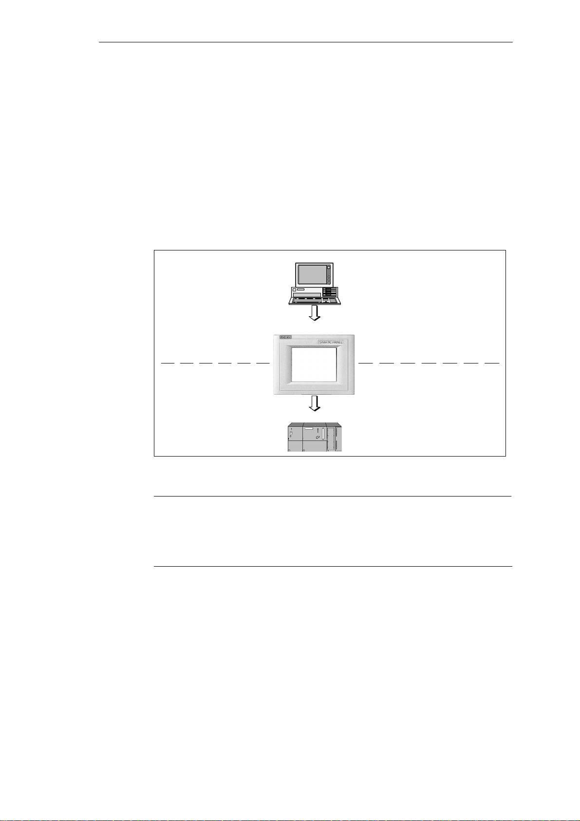
Configuring using ProTool/Pro CS, ProTool and ProTool/Lite
Graphics, texts and operating and display elements which need to be represented
on the operating units must first be created on a configuration computer (PC or
PU) using the configuration software SIMATIC ProTool/Pro CS, ProTool or
ProTool/Lite. The configuration computer must be connected to the operating unit
in order to download the project to the operating unit (refer to “Configuration
phase” in Figure 1-1).
Once the project has been successfully downloaded, connect the operating unit to
the PLC. The operating unit can then communicate with the PLC and respond
according to the information configured for running the program in the PLC (refer to
“Process control phase” in Figure 1-1).
Introduction
PC/PU
Configuration phase
TP170 A / TP170 B / OP170 B
PLC
Process running phase
Figure 1-1 Configuration and process running phase
Create project data
Save project data
Test project
Simulate project
Download project data
Connected to PLC
Note
The units can be configured, as required, using the configuration software
ProTool/Pro CS, ProTool or ProTool/Lite. Throughout this manual, the term
ProTool CS (CS: Configuration System) is used to represent all three software
variants.
TP170 A, TP 170 B, OP170 B Equipment Manual
Release 07/00
1-3
Page 16
Introduction
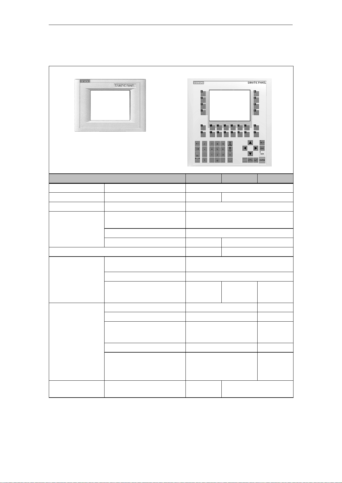
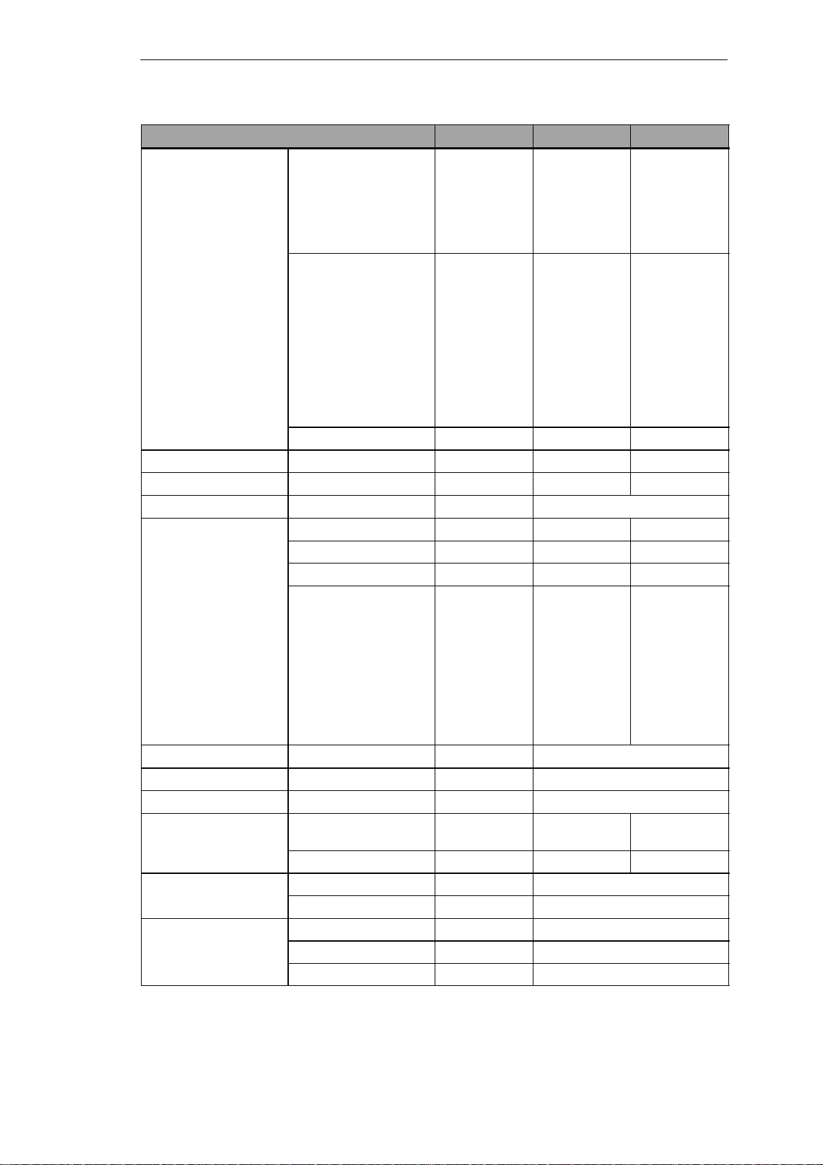
Overview of units
TP170 A, TP170 B
TP170 A TP170 B OP170 B
Processor Type 32 bit RISC
Memory Memory for configuration 256 kByte 512 kByte
Software Operating system MicrosoftR WindowsR CE
Ser. interface 1 Physics 1 ´ RS232 (9-pin)
S7 connection MPI/PROFIBUS-DP
Max. baud rate 1.5 MB 12 MB
Ser. interface 2 – RS232
Display Active screen area (W ´ H) in
mm
Resolution (pixels) 320 ´ 240
Colors 4BlueMode 4BlueMode
Operating elements Touch Screen ✔ –
Matrix keyboard – ✔
Function keys with configurable
functions
Those usable as softkeys – 14
Labeling the function keys – System-
Special features S External memory extension:
-- Slot for CF card
OP170 B
1 ´ RS422/RS485
211 ´ 158 (6’’)
4BlueMode
or
16 colors
– 24
(18 with
LEDs)
specific with
labelling
strips
– ✔
1-4
TP170 A, TP 170 B, OP170 B Equipment Manual
Release 07/00
Page 17

Further information
Detailed information on the technical data of the operating units is provided in
Appendix A of this manual.
Detailed descriptions of the creation of projects for the operating unit and
configuration software functions are provided in the ProT ool Configuring
Windows-based Systems user’s guide and in the online help for ProTool CS.
Connection of the operating unit to the PLC is described in the Communication for
Windows-based Systems user’s manual.
Any new information which could not be taken into account for printing in the
guides is provided in the Readme.wri file on the ProTool CD.
Introduction
TP170 A, TP 170 B, OP170 B Equipment Manual
Release 07/00
1-5
Page 18

Introduction
1-6
TP170 A, TP 170 B, OP170 B Equipment Manual
Release 07/00
Page 19
Functionality
2
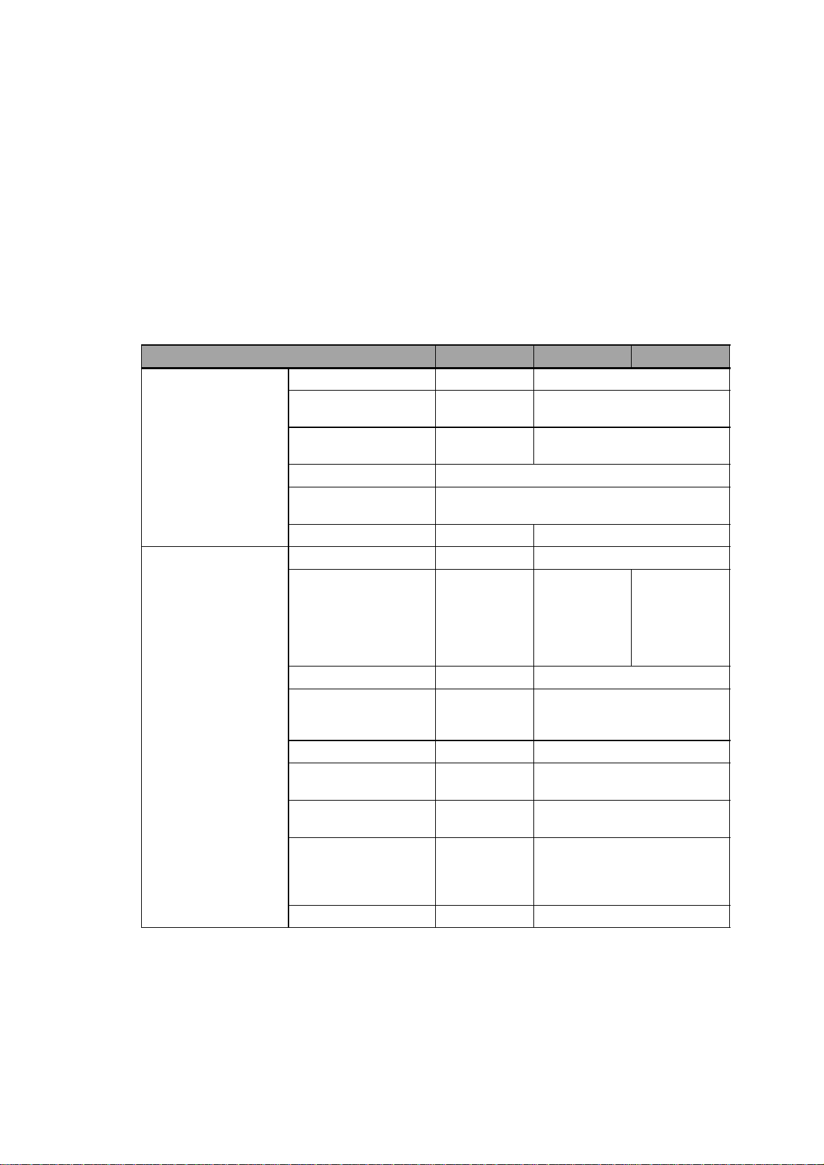
The table below summarizes the functional scope of the operating units. The values specified
are the maximum values which can be managed by the units. The values are limited by the size
of the memory used.
Function TP170 A TP170 B OP170 B
Event messages Number 100 400
Display Message view Message line, message window/
message page, message view
View all queued
messages
Message length per line 70 characters
Process values in
message text
Edit messages – ✔
Alarm messages Number – 400
Display – Message
Type of display – first/last, selectable
View all queued
messages
Message view Message page/Message view
8
window/
message page/
message view
– In message page/message view
1)
1)
Message line/
message
window/
message
page/message
view
Message length per line – 70 characters
Process values in
message text
Acknowledge individual
alarm messages
Acknowledge several
alarm messages
simultaneously (group
acknowledgement)
Edit messages – ✔
TP170 A, TP 170 B, OP170 B Equipment Manual
Release 07/00
– 8
– ✔
– 16 acknowledgment groups
2-1
Page 20
Functionality
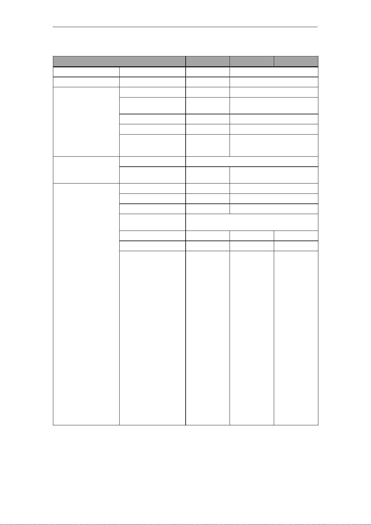
Function TP170 A TP170 B OP170 B
ALARM_S Display S7 messages – ✔
Message logging Output to printer – ✔
Volatile message
buffer
Message acquisition Time of occurrence Date/Time
Screens Number 20 100
Capacity – 128 message events
View event/alarm
messages
Delete – ✔
Print – ✔
Message events
queued simultaneously
(max.)
Message events Arrived,
Fields per screen 20 50
Tags per screen 20 50
Complex elements per
screen
View ✔ ✔ ✔
Print (hardcopy) – ✔ ✔
Screen objects
–/– ✔/✔
16 64
Arrived, departed, acknowledged
Departed
5
S Graphics ✔ ✔ ✔
S Tex t ✔ ✔ ✔
S Output field ✔ ✔ ✔
S Input field ✔ ✔ ✔
S Symbolic output field – ✔ ✔
S Selection field – ✔ ✔
S Date/Time – ✔ ✔
S Graphics list – ✔ ✔
S Vector graphic – ✔ ✔
S Button – ✔ ✔
S Status button ✔ ✔ ✔
S Switches – ✔ ✔
S Hidden button – ✔ ✔
S Trend graphic – ✔ ✔
S Bar ✔ ✔ ✔
S Message view – ✔ ✔
2-2
TP170 A, TP 170 B, OP170 B Equipment Manual
Release 07/00
Page 21
Functionality
OP170 BTP170 BTP170 AFunction
Screens Screen objects
S Simple message
view
✔ ✔ ✔
S Password list – ✔ ✔
S Recipe view – ✔ ✔
Operator guidance
S Dynamic attributes – ✔ ✔
S Call/Hide objects – ✔ ✔
S Help text – ✔ ✔
S TAB sequence – – ✔
S Icons for softkeys – – ✔
S LEDs in function
keys
Fixed window – ✔ ✔
Limit value monitoring Inputs/outputs ✔ ✔ ✔
Conversion functions Inputs/outputs – ✔ ✔
Tags Number 100 250
Help text Lines/characters – 7/35 7/35
For messages – ✔ ✔
For screens – ✔ ✔
For screen objects
– – ✔
S Input field – ✔ ✔
S Selection field – ✔ ✔
S Button – – ✔
S Status button – – ✔
S Switches – – ✔
S Hidden button – – ✔
Trends Number – 50
Graphic objects Number 20 50
Text elements Number 100 1000
Print functions Hardcopy of screen
content
Direct message logging – ✔ ✔
Password protection Number of passwords 1 50
Password level – 10 (0..9)
Recipes Number – 20
Data records per recipe – 50
Entries per recipe – 60
– ✔ ✔
2)
TP170 A, TP 170 B, OP170 B Equipment Manual
Release 07/00
2-3
Page 22

Functionality
OP170 BTP170 BTP170 AFunction
Online language
change
Screen settings Contrast ✔ ✔ ✔
Scheduler Trigger functions
Connections
Communication SIMATIC S5
3)
Number of languages 1 3
– ✔ ✔
cylically or once
Number 1 4
S AS511
S PROFIBUS-DP
SIMATIC S7/M7
4)
–
–
✔
✔
S MPI ✔ ✔ ✔
S PROFIBUS-DP ✔ ✔ ✔
SIMATIC 505
S NITP
S PROFIBUS-DP
Connection to PLCs from other manufacturers
Allen Bradley
(PLC-5, SLC 500)
S DF1
S DH+
S DH485
LG (Lucky Goldstar)
5)
5)
–
–
–
–
–
✔ ✔ ✔
✔
✔
✔
✔
✔
S GLOFA GM
Modicon
✔ ✔ ✔
S Modbus
Mitsubishi FX – ✔ ✔
Telemecanique TSX
S Adjust
S Uni-Telway
–
–
✔
✔
✔
✔
✔
✔
✔
✔
✔
✔
✔
1) Total number for event and alarm messages
2) Limited by storage medium
3) With SIMATIC S7
4) With adapter
5) Via external module
2-4
TP170 A, TP 170 B, OP170 B Equipment Manual
Release 07/00
Page 23
Commissioning
In this chapter
This chapter provides information on:
S starting up the operating unit for the first time (Page 3-3)
S restarting the operating unit (Page 3-4)
S options for download mode (Page 3-6)
S testing the project on the operating unit (Page 3-10)
S downloading the project back from the TP170 B and OP170 B (Page 3-12)
S backup/restore the internal Flash memory using the TP170 B and
OP170 B (Page 3-14)
Operating the operating units in the start-up phase
TP170 A:
Select the required object in the Start menu (Figure 3-1) and Configuration menu
(Figure 3-4) by touching the relevant button.
TP170 B:
Select the required object in the Start menu (Figure 3-2) and Configuration menu
(Figure 3-5) by touching the relevant button.
OP170 B:
Proceed as follows to operate the Start menu (Figure 3-3) and Configuration menu
(Figure 3-5)::
3
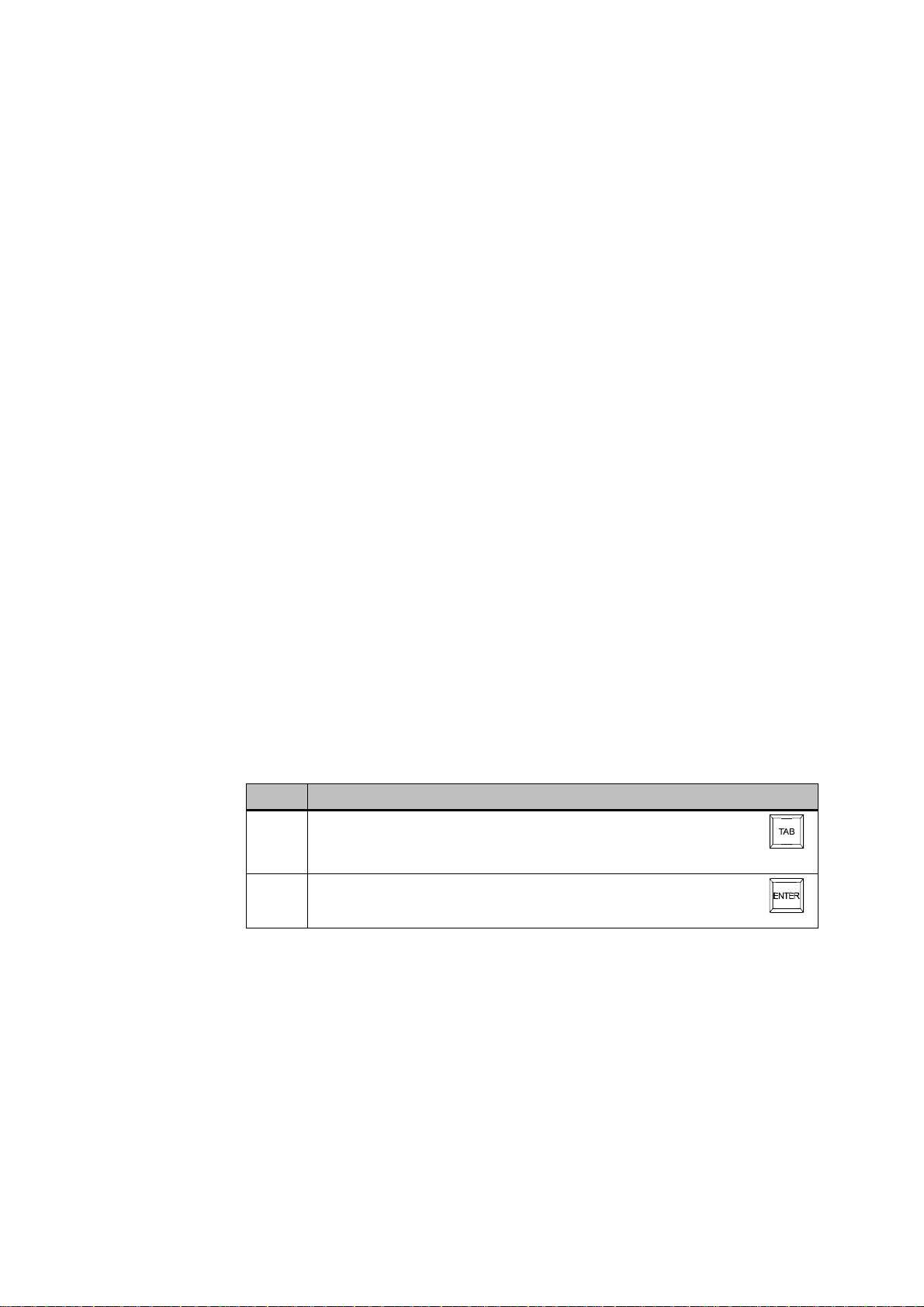
Step Procedure
1 Select the object to be operated (button, check box or input field) using
the Tabulator key.
The object currently selected is marked by a border or a different color.
2 S Buttons/Check boxes:
Press the Enter key in order to trigger the marked button or
activate/deactivate the marked check box.
TP170 A, TP 170 B, OP170 B Equipment Manual
Release 07/00
3-1
Page 24

Commissioning
Further information on operating the units is provided in the following chapters:
S General Operation:
S Operating Special Screen Objects:
TP170 A, TP170 B: Chapter 4
OP170 B: Chapter5
TP170 A: Chapter 6
TP170 B, OP170 B: Chapter7
3-2
TP170 A, TP 170 B, OP170 B Equipment Manual
Release 07/00
Page 25

3.1 Initial Startup
Procedure
When the operating unit is started up for the first time, no project has been loaded
on it. In order to download the necessary project data and the runtime software
from the configuration computer to the operating unit, proceed as follows,
observing the sequence:
Step Procedure
1 Depending on the settings in the Configuration menu (Figure 3-4 or 3-5), connect
the interface IF1A or IF2 (serial)
configuration computer using an appropriate standard cable.
2 Switch on the power supply for the operating unit.
Since no project has been loaded on the operating unit up to this point, it
automatically switches to Download mode. The operating unit displays the
message Connecting to host until it receives data from the configuration
computer or the button Cancel is pressed.
If the message Connecting to host does not appear, it is probable that the
options for download mode have been incorrectly set (refer to the note on
Page 3-8).
3 If data should be downloaded via an MPI connection, set the following
parameters on the configuration computer:
S OP address: 1
S Transmission rate: 187.5 k Baud
Start downloading the project on the configuration computer. Further settings
necessary on the configuration computer for the download operation are
provided in the ProTool Configuring Windows-based Systems user’s guide.
The configuration computer checks the connection to the operating unit. If the
connection is not available or defective, the corresponding error message
appears.
If downloading from the configuration computer is terminated as a result of a
compatibility conflict, please continue as described in Chapter 14.
If the connection is correct, the project data is downloaded to the operating unit.
Following successful downloading, the operating unit restarts and displays the
start screen of the project that has just been loaded.
Commissioning
1)
or IF1B (MPI) of the operating unit to the
1) TP170 A: IF1A
TP170 B, OP170 B: IF2
TP170 A, TP 170 B, OP170 B Equipment Manual
Release 07/00
3-3
Page 26

Commissioning
3.2 Recommissioning
Purpose
During recommissioning, a project already loaded on the operating unit is replaced
by another. In this case, the project data is downloaded from the configuration
computer to the operating unit.
The following options are available to switch the operating unit to Download mode:
S Start downloading manually during the operating unit start-up phase.
S Start downloading automatically while the operating unit is in operation.
S Start downloading via a correspondingly configured operating element while the
operating unit is in operation (refer to Page 9-7).
Start downloading manually during the operating unit start-up phase
Step Procedure
1 Connect interface IF1A or IF2 (serial)1), or IF1B (MPI), on the operating unit to
the configuration computer using an appropriate standard cable.
2 Switch on the power supply for the operating unit.
3 If necessary, check the interface settings in the Configuration menu (Figure 3-4
or 3-5) and adapt them as required.
4 During the operating unit start-up phase, the menu illustrated in Figure 3-1, 3-2
or 3-3 appears briefly. Press the Download button to set the operating unit to
Download mode before the start-up routine is completed.
The operating unit continues to display the message Connecting to host
until it receives data from the configuration computer or the Cancel button is
pressed.
If the message Connecting to host does not appear, it is probable that the
options for download mode have been incorrectly set (refer to the note on
Page 3-8).
5 If downloading should be performed via an MPI connection, set the OP address
and transmission rate valid for the operating unit on the configuration computer
(refer to the note on Page 3-5).
Start downloading the project on the configuration computer.
The configuration computer checks the connection to the operating unit. If the
connection is not available or defective, the configuration computer issues the
corresponding error message.
If downloading from the configuration computer is terminated as a result of a
compatibility conflict, please continue as described in Chapter 14.
If the connection is correct, the new project is downloaded to the operating unit.
Following successful downloading, the operating unit restarts and displays the
start screen of the projects that has just been loaded.
3-4
1) TP170 A: IF1A
TP170 B, OP170 B: IF2
TP170 A, TP 170 B, OP170 B Equipment Manual
Release 07/00
Page 27

Commissioning
Start downloading automatically when the operating unit is in operation
The operating unit can be switched automatically to Download mode from normal
operation as soon as downloading is started on the connected configuration
computer. This option is especially recommended for the test phase of a new
project because the transfer is performed without intervention on the operating
unit. A condition for this is that the following settings have been defined in the
Configuration (TP170 A: Figures 3-4, TP170 B and OP170 B: Figure 3-5):
MPI connection:
S Option MPI Transfer Enable is activated
S Option MPI Transfer Remote Control is activated
Serial connection:
S Option Serial Transfer Enable is activated
S Option Serial Transfer Remote Control is activated
A detailed description of the settings possible in the Configuration menu is
provided on Page 3-8.
Note on MPI transfer
The bus parameters (e.g. MPI address, baud rate etc.) are read out of the project
currently loaded on the operating unit.
Only use these parameters when downloading a new project, even if different
parameters are configured for the new project because the new parameters only
take effect after downloading has been completed successfully.
TP170 A, TP 170 B, OP170 B Equipment Manual
Release 07/00
3-5
Page 28
Commissioning
3.3 Options for Download Mode
Overview
The following options can be set for download mode:
S Automatic switching to download mode from normal operation when data
transfer is initiated from the connected configuration computer
S Download mode can be restricted to a specific connection type so that
downloading can only occur either via a serial connection or an MPI connection
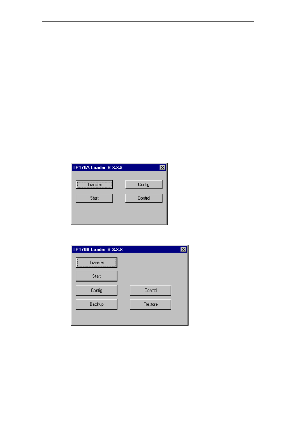
Call in Configuration menu
The options for Download mode can only be set when the operating unit is in its
start-up phase. During the start-up phase, the Start menu appears briefly
(TP170 A: Figure 3-1, TP170 B: Figure 3-2, OP170 B: Figure 3-3). Press the
Config button to call in the Configuration menu (TP170 A: Figures 3-4, TP170 B
and OP170 B: Figure 3-5).
3-6
Figure 3-1 TP170 A Start menu
Figure 3-2 TP170 B Start menu
TP170 A, TP 170 B, OP170 B Equipment Manual
Release 07/00
Page 29
Commissioning
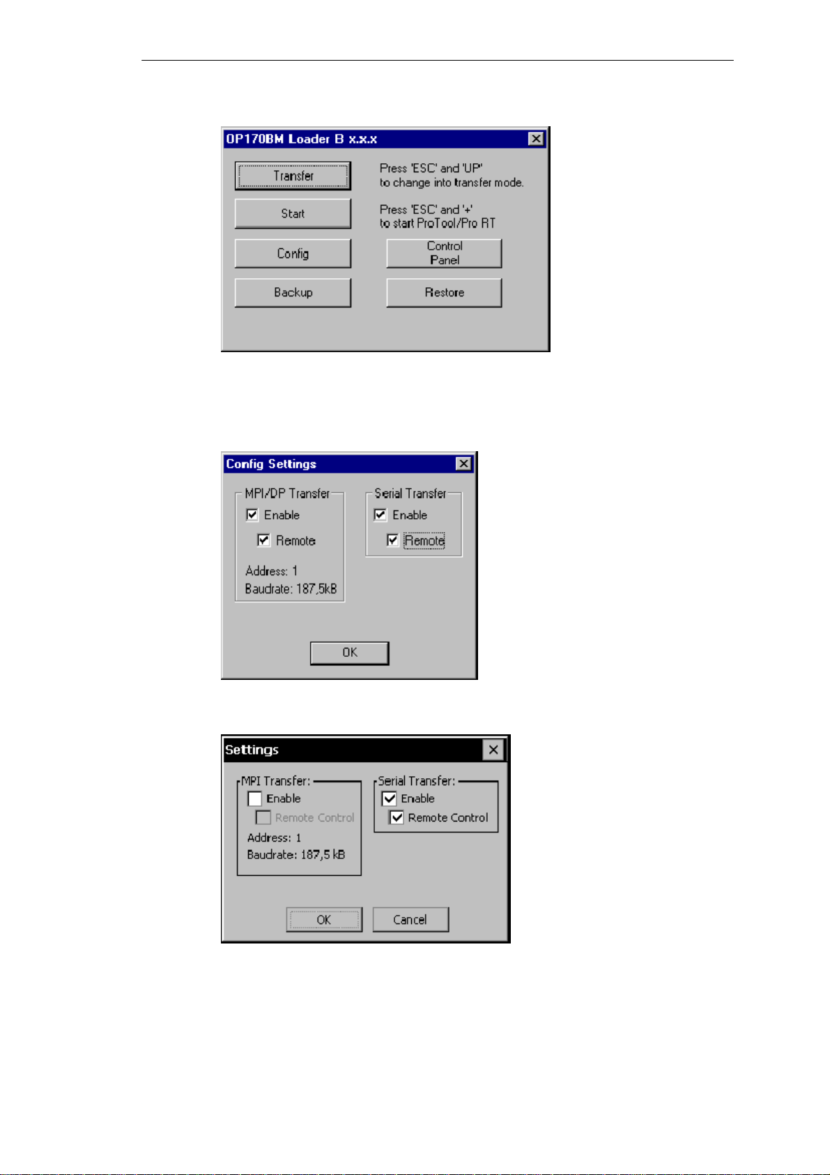
Figure 3-3 OP170 B Start menu
Information on the buttons Backup and Restore (TP170 B and OP170 B) is
available in Chapter 3.6.
Figure 3-4 TP170 A Configuration menu
Figure 3-5 TP170 B and OP170 B Configuration menu
TP170 A, TP 170 B, OP170 B Equipment Manual
Release 07/00
3-7
Page 30

Commissioning
Download mode settings
Setting the download options in the Configuration menu has the following effects:
S Option MPI Transfer Enable:
If this option is deactivated, the operating unit Download mode does not permit
data transfer via an MPI connection. Activate the option to enable connection
only via MPI or PROFIBUS-DP (SIMATIC S7).
S Option MPI Transfer Remote Control:
This option is only available if the option MPI Transfer Enable is activated.
When this option is active, the operating unit automatically switches from
normal operation to Download mode in the case of an MPI transfer from the
configuration computer.
S Option Serial Transfer Enable:
If this option is deactivated, the operating unit does not permit data transfer via
a serial interface (refer to the note below).
S Option Serial Transfer Remote Control:
This option is only available if the option Serial Transfer Enable is activated.
When this option is active, the operating unit automatically switches from
normal operation to Download mode in the case of a serial transfer from the
configuration computer.
Press the OK button to confirm the settings currently defined for the download
options. The Configuration menu is closed and the Start menu appears.
Press the Cancel button to close the Configuration menu and access the Start
menu. Any modifications made to the settings are rejected.
The group “MPI Transfer” displays both bus parameters “MPI address” and “Baud
Rate”. These parameters are valid for the project currently loaded on the operating
unit.
Caution
!
When the option Remote Control is active, ensure that the operating unit is not
inadvertently switched to download mode from the configuration computer when in
normal operation.
Note
If the options MPI Transfer Enable and Serial Transfer Enable are deactivated, it is
not possible to download a project from the configuration computer to the
operating unit.
3-8
TP170 A, TP 170 B, OP170 B Equipment Manual
Release 07/00
Page 31

Exit Start menu
If the operating unit still has no project, it automatically switches to download mode
after approx. 10 seconds after having been switched on. Press the Download
button to switch the operating unit to Download mode manually.
If the operating unit contains a project, it is started automatically approx.
10 seconds after being switched on. The project can be started manually by
pressing the Start button.
Commissioning
TP170 A, TP 170 B, OP170 B Equipment Manual
Release 07/00
3-9
Page 32

Commissioning
3.4 Testing a Project on the Operating Unit
Conditions
In order to switch the operating unit between the operating modes OFFLINE and
ONLINE, the function Change_mode must be linked to an operating element in the
project.
Testing on the configuration computer
The material supplied with ProTool contains a simulation program which can be
used to test the project on the configuration computer without the necessity of
connecting a PLC or operating unit. Detailed information on this is provided in the
ProTool Configuring Windows-based Systems and in the online help to
ProTool CS.
Testing without a PLC connected (OFFLINE mode)
After setting the operating unit to operating mode OFFLINE, the individual project
functions can be tested without them being affected by the PLC. PLC tags are not
updated in OFFLINE mode.
Step Procedure
1 Switch the operating unit to operating mode OFFLINE (refer to Page 9-7).
2 Check all the c onfigured screens in respect of correct representation.
3 Check the screen hierarchy.
4 Check the input fields.
5 Test the function keys.
If faults occur when executing the individual steps, download the project again.
3-10
TP170 A, TP 170 B, OP170 B Equipment Manual
Release 07/00
Page 33

Testing with a PLC connected (ONLINE mode)
When a PLC is connected, it is possible to test the communication between the
operating unit and PLC in ONLINE mode. This includes checking that the correct
data areas have been configured.
Step Procedure
1 Connect the operating unit to the PLC.
2 Test all the items in the project for which communication with the PLC is
necessary e.g.:
S messages,
S print functions
S automatic message logging
S selecting screens, etc.
Commissioning
TP170 A, TP 170 B, OP170 B Equipment Manual
Release 07/00
3-11
Page 34

Commissioning
3.5 Download Back (TP170 B and OP170 B)
Purpose
During downloading, generally only the run-capable project (*.fwd) which has been
generated is downloaded on the operating unit. If the original project file is to be
used for further development of the project or for fault analysis, it must remain on
the configuration computer.
Not only the generated project can be stored on the TP170 B and OP170 B units,
but also the project source file (*.pdb), so that it can be retrieved (downloaded
back) from the operating unit later, if necessary.
Advantage
After downloading a project back, it can be analyzed and modified even if the
original configuration computer cannot be accessed or the source file (*.pdb) on it
for the project is no longer available.
Conditions
The following conditions must be fulfilled in order to retrieve the source file from the
run-capable project file:
S The operating unit must be equipped with a memory card.
S Downloading of the current project file from the configuration computer to the
operating unit must be performed using the option Download Back Enabled.
What happens during download/download back?
In the case of downloading including transfer of the source file, the project is
compressed from the source format (*.pdb) and downloaded to the operating unit
as a *.pdz file. After downloading back, the file is decompressed in the ProTool CS
configuration software.
The project must be given a new name on the configuration computer.
Note
S The downloaded back, decompressed project file (*.pdb) can only be opened
with a ProTool CS whose version number is greater or equal to that of the
configuration software with which the project was created.
S ProTool CS cannot check whether the source file on the operating unit matches
the project actually run on it. If downloading is performed at any time without
the option “Download Back” being activated, it is possible that old project data
is on the operating unit which no longer matches the current project.
3-12
TP170 A, TP 170 B, OP170 B Equipment Manual
Release 07/00
Page 35

Instructions
Commissioning
Downloading a project back from the operating unit:
Step Procedure
1 Select the menu option File ® Download Back in ProTool CS on the
configuration computer.
2 Select one of the two following connection types between the operating unit and
configuration computer in the Download Back Settings dialog:
S Serial
S MPI/PROFIBUS-DP (via network connection)
3 Click on Edit and set the connection parameters:
S for serial: connection and baud rate
S for MPI: OP address of the operating unit
The settings are saved and correspondingly reapplied when downloading back
is triggered at a later date.
4 Switch the operating unit to download mode manually or using Remote Control
according to the setting in the Configuration menu.
5 Start downloading back with OK.
Download back automatically switches the operating unit download mode.
Note
A condition for this is that the download type implemented is set on the operating
unit (refer to Page 3-8).
Following successful downloading back, the Save as dialog opens.
6 Enter a new name or select an existing project to be overwritten and click on
Save.
The project retrieved is saved and automatically opened in ProTool CS.
TP170 A, TP 170 B, OP170 B Equipment Manual
Release 07/00
3-13
Page 36

Commissioning
3.6 Backup/Restore the Internal Flash Memory (TP170 B and OP170 B)
Purpose
The functions Backup and Restore provide the following options:
S Creating a backup copy of the entire project on memory card,
S Recoveringastoredprojectinthecaseofafault,
S Updating a project regardless of where the operating unit is in use, without a
configuration computer.
Conditions
The two functions, Backup and Restore, are only available in the Start menu
(TP170 B: Figure 3-2, OP170 B: Figure 3-3) during the operating unit’s start-up
phase. In order to access the Start menu, either the Exit_runtime function must be
called in or the unit restarted.
Backup
Insert the memory card in the expansion slot before starting the Backup/Restore
process.
Notes on memory cards are provided in Chapter 12.
During a backup, the entire content of the internal Flash memory is copied onto an
external storage medium. Both system data and configuration data are copied.
This data is stored under Storage Card/pdz.
3-14
TP170 A, TP 170 B, OP170 B Equipment Manual
Release 07/00
Page 37

Restore
Commissioning
Proceed as follows to create a backup copy of the internal Flash memory:
Step Procedure
1 Deactivate the write protection on the memory card, if set.
2 Insert the memory card in the slot (TP170 B: Figure 11-4 on Page 11-6,
OP170 B: Figure 11-6 on Page 11-9).
3 Call in the operating unit Start menu (TP170 B: Figure 3-2, OP170 B: Figure 3-3).
4 Start the Backup process by using the Backup button.
5 Confirm the deletion of any existing backup files beforehand.
6 When the data has been completely downloaded, the operating unit issues a
message.
7 Remove the memory card from the operating unit.
8 Activate the write protection on the memory card, if available.
In the case of a restore process, the content of a Flash memory stored on an
external storage medium is reloaded into the internal Flash memory. Both system
data and configuration data are copied. Prior to this, the operating unit Flash
memory is completely cleared following confirmation.
Proceed as follows to restore the content of the internal Flash memory:
Step Procedure
1 Activate the write protection on the memory card, if available.
2 Insert the memory card in the slot (TP170 B: Figure 11-4 on Page 11-6,
OP170 B: Figure 11-6 on Page 11-9).
3 Call in the operating unit Start menu (TP170 B: Figure 3-2, OP170 B: Figure 3-3).
4 Start the restore process by clicking on the Restore button.
5 Before starting the Restore process, the operating unit checks the compatibility
with the data to be restored. In the case of incompatibility, the operating unit
terminates the process and issues the relevant message.
6 Confirm that the internal Flash memory.
7 When the data has been completely downloaded, the operating unit issues a
message.
8 Remove the memory card from the operating unit.
9 Start up the operating unit again.
TP170 A, TP 170 B, OP170 B Equipment Manual
Release 07/00
3-15
Page 38

Commissioning
3-16
TP170 A, TP 170 B, OP170 B Equipment Manual
Release 07/00
Page 39

Operating Touch Panels TP170 A and TP170 B
Operating concept
The screen is used to observe the operating status of the machine or system being
monitored and, at the same time, to intervene directly in the process running
simply by touching the buttons and input fields displayed.
4.1 Operating Touch Elements
Definition
Touch elements are contact-sensitive operating elements provided on the touch
panel screen, such as buttons, input fields and message windows. Their operation
is basically no different from pressing conventional keys. Touch elements are
operated by touching them lightly with your finger or a suitable object.
Note
4
Never use pointed or sharp instruments to operate the Touch Panel to prevent
damage to the plastic surface of the touch screen.
Caution
!
TP170 A, TP 170 B, OP170 B Equipment Manual
Release 07/00
Be sure to touch only one point on the touch panel screen element. Never touch
more than one touch element at a time. Otherwise, an action may be
unintentionally initiated.
4-1
Page 40

Operating Touch Panels TP170 A and TP170 B
Operation acknowledgement
As soon as the touch panel detects valid contact with a touch element, it responds
by displaying a visual acknowledgement. An acknowledgment is independent of
communication with the PLC. It is not an indication of the required action actually
having been executed.
The type of visual acknowledgement is dependent on the operating element
touched:
S Buttons
In the case of 3D-effect configurations, visual representation is distinguished
according to the statuses touched and untouched. Examples of representation
are illustrated below by means of the Status button:
UntouchedTouched
S Input fields
After an input field has been touched, the screen keyboard illustrated in
Figure 4-1 appears as acknowledgement of the operation.
4-2
TP170 A, TP 170 B, OP170 B Equipment Manual
Release 07/00
Page 41

4.1.1 Enter Numeric Values
Principles of operation
In order to enter numeric values, the touch panel automatically displays a numeric
screen keyboard after touching an input field, for example. Keys on the keyboard
which are available for operation are highlighted as 3D keys, those not available
are simply displayed as areas. After completing the input, the screen keyboard is
automatically hidden.
Figure 4-1 illustrates an example of the screen keyboard for entering numeric
values. The keys
example. The Help key (TP170 B) is only displayed when help text has been
configured for that particular input field.
A to F for entering hexadecimal values are inoperable in this
Operating Touch Panels TP170 A and TP170 B
Figure 4-1 Screen keyboard for numeric values
TP170 A, TP 170 B, OP170 B Equipment Manual
Release 07/00
4-3
Page 42

Operating Touch Panels TP170 A and TP170 B
Meanings of buttons
Table 4-1 Significance of buttons
Button Function Purpose
0
...
Enter character Enter character via the
Move input position
to the left
keyboard in normal or Shift
level.
Move current input position
one character to the left.
Procedure
Move input position
to the right
Cancel (Escape) Discard input and close the
Enter Confirm input and close the
Call in help text Calls in the configured help
Backspace Deletes the character to the
Move current input position
one character to the right.
screen keyboard.
screen keyboard.
text.
left of the current cursor
position.
Numeric values are entered character by character using the input keys on the
screen keyboard. If a value already exists in the field, this is deleted on entering
the first character. After beginning entering a value, it is impossible to exit from the
field without either confirming the entry or canceling it.
Characters entered are aligned to the right. On entering a new character, all those
already entered are shifted one position to the left (pocket calculator format).
4-4
Invalid characters are rejected and an error message appears. On exceeding the
maximum number of characters, the last character entered is overwritten.
Confirm the value entered by pressing
ENTER or cancel the input by pressing ESC.
The window is closed in both cases.
TP170 A, TP 170 B, OP170 B Equipment Manual
Release 07/00
Page 43

Limit value test
Limit values can be configured for numeric input fields. In this case, values
entered are only accepted when they lie within the limits configured. If an attempt
is made to enter a value which is outside the configured limits, it is rejected and the
original value automatically reinserted.
4.1.2 Enter Alphanu meric Values
Principles of operation
In order to enter alphanumeric values, the touch panel automatically displays an
alphanumeric screen keyboard after touching an input field. Keys on the keyboard
which are available for operation are highlighted as 3D keys, those not available
are simply displayed as areas. After completing the input, the screen keyboard is
automatically hidden.
Operating Touch Panels TP170 A and TP170 B
Figure 4-2 illustrates an example of a normal screen keyboard to enter
alphanumeric values. The Help key (TP170 B) is only displayed when help text has
been configured for that particular input field.
Figure 4-2 Screen keyboard for alphanumeric values, normal level
Table 4-1 on Page 4-4 explains the significance of the individual keys.
TP170 A, TP 170 B, OP170 B Equipment Manual
Release 07/00
4-5
Page 44

Operating Touch Panels TP170 A and TP170 B
Keyboard levels
The alphanumeric screen keyboard has two levels:
S Normal level
S Shift level
Toggle between the two levels by pressing the
SHIFT key.
Procedure
4-6
Figure 4-3 Screen keyboard for alphanumeric values, Shift level
Characters entered are aligned to the left. Following each entry, the cursor skips to
the right to the next entry position.
If an alphanumeric input field already contains a value, it is displayed in reversed
colors and deleted as the new value is entered. In order to edit an existing value,
press one of the cursor keys as the first entry. On pressing
remains on the first character, after pressing
CURSOR RIGHT it skips to the second
CURSOR LEFT, the cursor
character. In this case, the value reverts back to its normal representation and can
be edited.
On exceeding the maximum number of characters, the last character entered is
overwritten.
TP170 A, TP 170 B, OP170 B Equipment Manual
Release 07/00
Page 45

Operating Touch Panels TP170 A and TP170 B
Confirm the value entered by pressing ENTER or cancel the input by pressing ESC.
The window is closed in both cases.
The current input position is displayed in inverse colors. Invalid characters (e.g.
values greater than 23 when specifying the time for a clock) are rejected and an
error message appears. On exceeding the maximum number of characters which
can be entered, the last character entered is overwritten.
Note
The characters available and layout of the alphanumeric screen keyboard are
independent of the language set on the operating unit.
4.1.3 Enter Symbolic Values o n the TP170 B
Purpose
Procedure
Values entered in a symbolic input field are not entered character-by-character but
are selected from a list provided, e.g.:
Figure 4-4 Symbolic input field, opened (example)
Touch the symbolic input field on the operating unit touch screen. In this case, the
selection list opens up immediately. After selecting an element from the list, the
selection list is closed and the selected text appears in the list box.
TP170 A, TP 170 B, OP170 B Equipment Manual
Release 07/00
4-7
Page 46

Operating Touch Panels TP170 A and TP170 B
4.2 Calling in Help Text on the TP170 B
Purpose
Configuration planners can provide users with additional information on messages,
screens and input fields in the form of help texts. Help text, concerning an input
field for example, may provide information on permissible value ranges (refer to
Figure 4-5) or, in the case of an alarm message, information related to the cause
and its elimination.
Enter temperature setpoint for Tank_1
(Range 40...80 _C)
Procedure
Figure 4-5 Help text for an input field (example)
S Call in help on messages
Touch the following key in the message window, on the message page, in the
message buffer or the message view
S Call in help on input fields
Touch the Help key on the screen keyboard. This key only appears if a
configured help text exists.
S Call in help to screen
If the function Display Information Text has been assigned to a button, for
example, in the project, touch that button to call in the help text configured for
the current screen.
4-8
TP170 A, TP 170 B, OP170 B Equipment Manual
Release 07/00
Page 47

Operating Keyboard Unit OP170 B
Operating concept
The operating status of the machine or system to be monitored can be observed on
the OP170 B screen and the process currently running directly influenced by using
the keyboard.
This chapter provides information on the general operating procedures for the
OP170 B. Information regarding operation for special screen objects is provided in
Chapter 6.
5.1 Integrated Keyboard
Keypads
The OP170 B keyboard consists of two functional keypads (Figure 5-1):
S Function keys/Soft keys (keys
S System keys
K1 to K10 and F1 to F14)
5
Figure 5-1 Assignment of OP170 B keypads
TP170 A, TP 170 B, OP170 B Equipment Manual
Release 07/00
5-1
Page 48

Operating Keyboard Unit OP170 B
Function keys for global function assignment
A function key for global function assignment always triggers the same action on
the OP170 B or in the PLC regardless of the screen currently open (global
significance on the OP170 B). These actions could include:
S Open screen
S Display current alarm messages
S Print screen (hardcopy)
The following function keys can be assigned during configuration:
K1 to K10
to F14
F1
Function keys for local function assignment (softkeys)
A function key for local function assignment (softkey) can trigger different actions
on the OP170 B or in the PLC according to the screen currently open (local
significance of current screen). If configured, the function of a softkey is indicated
by an icon located at the edge of the current screen.
All the function keys located directly at the edge of the screen can be assigned
locally significant functions during configuration. In the case of the OP170 B, this
relates to the keys
F1 to F14.
Note
If a function key is pressed directly following changing screens, the corresponding
function associated with the new screen is triggered before the screen is
generated.
5-2
TP170 A, TP 170 B, OP170 B Equipment Manual
Release 07/00
Page 49

System keys
Table 5-1 Functions of the system keys
Operating Keyboard Unit OP170 B
Key Function Purpose
Shift Switches the assignment of the input keys
from numeric to alphanumeric input.
S No LED lights up:
Numeric assignment is active. Press the
key once to switch to alphanumeric
assignment.
S An LED lights up:
The left or right alphanumeric assignment
is active. Each time the key is pressed
switches through left, right and off.
Activate editing
mode, Insert/Delete
character
Cancel S Deletes the character of a value entered
S Activates editing mode.
S Deletes or inserts individual characters.
Delete character in numeric keyboard
assignment. To insert characters, use the
Shift key to s witch to alphanumeric
assignment.
and resets the original value.
S Closes the active window.
Acknowledge Acknowledges the currently displayed alarm
message or all messages in an
acknowledgment group (group
acknowledgement).
The LED lights up as long as
unacknowledged alarm messages are
queued.
Display help text Opens a window with help text in respect of
the selected object (message, input field). The
LED indicates if help text exists for the
selected object.
Acknowledge S Accepts and ends the input.
S Opens a selection field for symbolic input.
S Triggers the function on the selected
button.
Tabulator Moves to the next screen object available for
selection in the configured tabulation
sequence.
Delete character Deletes the character to the left of the cursor.
Move cursor S Move to the next screen object available
TP170 A, TP 170 B, OP170 B Equipment Manual
Release 07/00
for selection to the right, left, above or
below the current screen object.
S Navigation in the screen object.
5-3
Page 50

Operating Keyboard Unit OP170 B
Table 5-1 Functions of the system keys, continued
PurposeFunctionKey
Only use in combination with other keys, e.g.
navigation in trend view (Page 7-26).
Only use in combination with other keys, e.g.
shift to capital letters.
Only for use with key combinations, e.g. open
selection field (Page 5-5).
Scroll one page back .
Scroll one page forward.
5-4
TP170 A, TP 170 B, OP170 B Equipment Manual
Release 07/00
Page 51

5.2 Key Combinations
General operation
Table 5-2 Key combinations
Key combination Function
Moves to the previous screen object available for selection in the
configured tabulation sequence.
Positions the cursor within a screen object, e.g. in an input field.
Skip to the start, e.g. of a selection list.
Operating Keyboard Unit OP170 B
Navigation
Skip to the end, e.g. of a selection list.
Opens a selection field.
Screen settings
Increase the screen contrast.
Reduce the screen contrast.
During the start-up phase
Switches the OP170 B to download mode.
As long as no data transfer is taking place, it is possible to exit
from download mode.
Other functions
Accepts the selected value in the selection field without closing
it.
S Changes the active window.
S Switches between basic area and window.
Mark all
Display the properties of the marked element
TP170 A, TP 170 B, OP170 B Equipment Manual
Release 07/00
5-5
Page 52

Operating Keyboard Unit OP170 B
Table 5-2 Key combinations, continued
FunctionKey combination
Continue to next field
Return to previous field
Open next tab control
Open previous tab c ontrol
Close dialog without saving
1) When the name of the tab c ontrol has the focus.
Operating screen objects using function keys
Screen objects assigned to buttons, e.g. message view, trend view or recipe view,
can also operated by means of function keys or softkeys. A condition for this is that
each relevant function has been linked to a function key or softkey in the project.
These functions are complied in ProTool CS within the Keyboard action for screen
objects.
1)
1)
5-6
TP170 A, TP 170 B, OP170 B Equipment Manual
Release 07/00
Page 53

5.3 Entering Values
Marking
On selecting an input field, the entire field content is marked by changing color.
After pressing a key (except a cursor key), the field content is deleted and the new
input displayed.
Operating Keyboard Unit OP170 B
Operation
After selecting a field, press the
SHIFT key and a cursor key simultaneously to clear
the marking on the field contents and enable the cursor to be moved freely within
the field.
Proceed as follows in order to enter values in an input field:
Step Procedure
1 Use the cursor keys to position the cursor on the desired input field.
2 Enter the value in the following form, according to the configuration:
S Numeric (Page 5-8)
S Alphanumeric (Page 5-9)
S Symbolic (Page 5-10)
3 Confirm the entry.
TP170 A, TP 170 B, OP170 B Equipment Manual
Release 07/00
5-7
Page 54

Operating Keyboard Unit OP170 B
...
5.3.1 Enter Numeric Values
Procedure
Numeric values are entered character-by-character using the input keys on the
keyboard. If a value already exists in the field, this is deleted on entering the first
character. After beginning entering a value, it is impossible to exit from the field
without either confirming the entry or canceling it.
Possible values
The following values are possible in numeric input fields:
Values Keys Description
Decimal
...
The input keys are numerically assigned.
Hexadecimal
Digits
Limit value check
Limit values can be configured for numeric input fields. In this case, values
entered are only accepted when they lie within the limits configured. If a value is
entered which lies outside the limits, the corresponding system message appears.
After they are cancelled, the original values are automatically reset.
,
...
...
,
To enter the characters A ...F use the Shift
key to switch to alphanumeric assignment.
The input keys are numerically assigned.
5-8
TP170 A, TP 170 B, OP170 B Equipment Manual
Release 07/00
Page 55

5.3.2 Enter Alphanumeric Values
Procedure
Alphanumeric values are entered character-by-character using the input keys on
the keyboard. Digits, letters and spaces are possible.
After entering a character, the cursor moves one space to the right. If the entry
exceeds beyond the maximum number of places, the OP170 B overwrites the last
character entered with each subsequent entry.
Input Keys Description
Digits
...
,
The numeric assignment is active when no
LED is on.
Operating Keyboard Unit OP170 B
Letters
The alphanumeric assignment is active when one of
the two LEDs is on.
...
TP170 A, TP 170 B, OP170 B Equipment Manual
Release 07/00
5-9
Page 56

Operating Keyboard Unit OP170 B
1Select
Symbolicinputfieldismarke
d.y
5.3.3 Enter Symbolic Values
Purpose
Values entered in a symbolic input field are not entered character-by-character but
are selected from a list provided, e.g.:
Figure 5-2 Symbolic input field, opened (example)
Procedure
Tip
Step Keys Description
1 Select
symbolic
input field
2 Open symbolic
input field
3 Select entry Moves cursor line by line.
4
Apply selection The value assigned to the selection becomes
or
Cancel
selection
(e.g.)
Symbolic inputfield is marked.
The selection list opens up.
valid. The symbolic input field is closed.
The original value is reapplied.
The symbolic input field is closed.
After pressing an alphanumeric key, the first list entry which begins with that
character is selected.
5-10
TP170 A, TP 170 B, OP170 B Equipment Manual
Release 07/00
Page 57

5.4 Call Help Text
Purpose
Help texts consist of additional information and operating instructions provided by
the configuration planner concerning messages, screens and operable screen
objects. Help text, concerning an input field for example, may provide information
on permissible value ranges (refer to Figure 5-3) or, in the case of an alarm
message, information related to the cause and its elimination.
Enter temperature setpoint for Tank_1
(Range 40...80 _C)
Operating Keyboard Unit OP170 B
Procedure
Figure 5-3 Help text for an input field (example)
Proceed as follows in order to call in the configured help text, e.g. for an input field:
Step Procedure
1 Select the required input field, e.g. using the Tabulator key.
2
3 The help text configured for the input field is displayed on the OP170 B in the
4
The LED in the HELP key lights up, indicating that a help text is available.
Press the HELP key.
language set. If a help text has also been configured for the current screen, it
is displayed too.
Press the ESC key to close the help text window.
TP170 A, TP 170 B, OP170 B Equipment Manual
Release 07/00
5-11
Page 58

Operating Keyboard Unit OP170 B
5-12
TP170 A, TP 170 B, OP170 B Equipment Manual
Release 07/00
Page 59

Screen Objects for TP170 A
In this chapter
This chapter introduces the screen objects which may be contained in a
configuration and explains their operation. It provides the following information:
S General operation (Page 6-2)
S Summary of screen objects (Page 6-4)
S Input field for date/time (Page 6-5)
S Input field for confidential password entry (Page 6-5)
S Status button (Page 6-6
S Messages (Page 6-7)
S Bars (Page 6-9)
6
TP170 A, TP 170 B, OP170 B Equipment Manual
Release 07/00
6-1
Page 60

Screen Objects for TP170 A
6.1 General Operation
In this chapter
This chapter contains information on how to operate screens and logging in and
out of the operating unit.
6.1.1 Operating Screens
What is a screen?
Screens visualize the progress of processes and display specified process values.
A screen contains logically related process data which the operating unit can both
display and modify by operating the individual values.
Screen partitions
A screen is basically composed of static and dynamic sections. The terms “static”
and “dynamic” do not refer to the possibility of dynamically positioning screen
partitions but to the connection to the PLC.
Static partitions, e.g. text and graphics, are not updated by the PLC. Dynamic
partitions, e.g. input and output fields, trend view and bars, are linked to the PLC
and display current values constantly read in from the PLC memory. Their
connection to the PLC is established by means of tags.
A summary of all the screen objects which the operating unit may contain is
provided on Page 6-4.
Select screen
There are several ways in which to select a screen:
S Button
Pressing a button opens the corresponding screen defined in the configuration.
S Input field
Enter the corresponding number of the screen to be viewed in the input field.
6-2
TP170 A, TP 170 B, OP170 B Equipment Manual
Release 07/00
Page 61

Screen Objects for TP170 A
6.1.2 Logging On and Off from the Operating Unit
Purpose
During the configuration, input fields and buttons can be protected against
unauthorized operation by assigning passwords. Important parameters and
settings can then only be modified by authorized personnel. The password is
defined at the moment the element is configured and cannot be modified via the
operating unit.
Login
If operating elements are to be assigned password protection in the configuration,
it must be possible for the operator to log in. In this case, the function Login_user
must be linked with an operating element, preferably an input field, in the
configuration.
Logoff
In order to access a password protected operating element during runtime, it is
necessary to log in on the operating unit. It is then possible to access all password
protected operating elements up to the point of logging off from the operating unit.
When correspondingly configured, it is also possible to log on via an input field for
confidential password entry. The character string entered is represented by
placeholders (*).
In order to rule out operation by unauthorized personnel, the login should not
remain active on the operating unit for too long a period of time. The following
options are available with which to log off from the operating unit:
S Configured logout time expires
If the operating unit is not operated by the user within the configured period
(logout time), he is automatically logged off from the operating unit.
S Log out of the operating unit
If the configuration links the function Logoff_user with an operating element, the
element can be used to log off from the operating unit.
Tip
It is possible to log off by entering an incorrect password.
TP170 A, TP 170 B, OP170 B Equipment Manual
Release 07/00
6-3
Page 62

Screen Objects for TP170 A
6.2 Overview of Screen Objects
Table 6-1 provides a summary of the various screen objects which a TP170 A
project may contain.
Table 6-1 Screen objects configurable for the TP170 A
Screen object Use/Description
Tex t Text is used during c onfiguration to label operating and
display elements, for example. Text can be configured
over several lines and cannot be altered on the
operating unit.
Graphics Graphics can be used in the configuration, e.g. to
represent a system or as an illustrative symbol for
configured display and operating elements.
Output field The output field displays the current value in numeric
or alphanumeric form.
Input field
Status button
Bar Bar graphs present a value in the form of a rectangular
Simple message view Special filter criteria for displaying pending messages
Enter a value in the input field. The values can be in
numeric or alphanumeric form. Entries which lie
outside the specified value range are rejected
according to the limit values which have been
configured.
The input can be protected by means of a password
A Status button is a display and operating element
which has one of two states: Touched and Untouched.
The states can be indicated by means of text or
graphics.
The Status button can be configured to be locking
(switch function) or non-locking (keying function).
area. The operating unit thus provides a clear
indication of how far the current value is from the limit
values, or if a setpoint value has been reached, at a
glance. Bars are often used to represent fill levels or
workpiece numbers.
Direction, scaling and labeling the axis can be
configured as required. In order to identify limit values,
limit value lines can be called in.
are configured in the message view.
Notes on operation are provided on Page 6-8.
.
6-4
TP170 A, TP 170 B, OP170 B Equipment Manual
Release 07/00
Page 63

Screen Objects for TP170 A
6.3 Input Field for Date/Time
Purpose
The input field for date and time serves to enter calendar dates and the time. The
input format is dependent on the language currently set on the operating unit. The
figure below illustrates examples of input fields for date and time in English
language format.
6.4 Input Field for Confidential Password Entry
Purpose
When a password is entered in the input field for confidential passwords, the
characters are represented by placeholders (*). The figure below illustrates an
example.
TP170 A, TP 170 B, OP170 B Equipment Manual
Release 07/00
6-5
Page 64

Screen Objects for TP170 A
6.5 Status Button
Purpose
The Status button is an operating and display element with the two states Pressed
and Released. Status buttons indicate the status of a unit which cannot be
determined from the operating unit (e.g. a motor). At the same time, it is also
possible to change the status of the unit concerned on the operating unit.
Behavior
The behavior of the Status button can be configured:
S Switch:
The switch has two stable states. It toggles from one state to the other each
time it is operated, and remains in the respective state until it is operated again.
S Key:
The button has a fixed, stable home position. When operated, it switches to the
status pressed and remains in this state as long as it is kept pressed. When
released, it automatically switches back to its released position.
Display
Functions which have been assigned to the Status button can be triggered, for
example, by the following configurable events:
S Status change
S Printing
S Releasing
If the status of a switch type Status button changes as a result of a modification of
configured tags, not through operation, the corresponding function is not executed.
The two indicator statuses of the types Switch and Button with acknowledgement
can be assigned different texts or graphics in /Pro CS which are displayed on the
Status button during runtime.
Figure 6-1 illustrates an example of a switch type Status button when pressed (left)
and not pressed (right).
Figure 6-1 The two statuses relate to the Status button when the Switch option is set
Operation
6-6
Touch the Status button on the operating unit.
TP170 A, TP 170 B, OP170 B Equipment Manual
Release 07/00
Page 65

6.6 Messages
What are messages?
Messages which appear on the operating unit indicate events and statuses related
to the control process and operating unit itself. A message can contain text and
tags.
The TP170 A differentiates between event messages and system messages:
S Event messages
indicate a status in the process, for example, Motor ON.
Event messages are configured. They are triggered when a bit is set in the
PLC.
S System Messages
are triggered by the operating unit. They are not configured.
System messages indicate, for example, incorrect operations or communication
faults. A time period can be considered for system messages in the
configuration software. This defines how long a system message appears on
the operating unit.
Screen Objects for TP170 A
A list of the most important system messages is provided in the Appendix C.
Message events
These messages are triggered according to events. Message events on the
TP170 A include:
S Message arrival
A message which has been triggered is considered as having arrived. As soon
as message is triggered, it is displayed in the operating unit message view and
is then considered as queued.
S Message departure
A message is considered as having departed when its configured time period
has expired or the event causing the message is no longer present. As soon as
a message has departed it is deleted from the message view.
TP170 A, TP 170 B, OP170 B Equipment Manual
Release 07/00
6-7
Page 66

Screen Objects for TP170 A
Message view
The TP170 A displays messages which have arrived in the message view. If
several messages are present simultaneously on the operating unit, the oldest
message in the queue is deleted.
It is possible to define specific views of the messages to be displayed in the
message view. Various filter criteria is available for this in the configuration
software.
The following can be configured
S Message categories (event and system messages)
S Number of columns
S Number of lines per message
S Sorting (oldest or latest message at the top)
S Maximum number of visible messages
The figure illustrates an example of a message view with the configured columns
S Date
S Time
S Message number
S Message states
S Message text
12.12.99 14:27:06 110001 K
Change to operating status ’online’
12.12.99 14:27:07 140001 K
Connection discontinued: Station 2, Rack 0, Slot 0
6-8
TP170 A, TP 170 B, OP170 B Equipment Manual
Release 07/00
Page 67

6.7 Bar graphs
Purpose
Bar graphs present a value in the form of a rectangular area. The operating unit
thus provides a clear indication of how far the current value is from the limit values,
or if a setpoint value has been reached, at a glance. Bar graphs can be used to
display fill levels or quantities, for example.
Display
It is possible to configure minimum and maximum values and the direction a bar
graph moves by increasing the tag value:
Figure 6-2 depicts the various states of a horizontal bar graph:
1. Value drops below the minimum value configured
2. Value lies within the configured display range
3. Value exceeds the maximum value configured
4. Value lies within the configured limit range
Screen Objects for TP170 A
Figure 6-2 Different bar states
TP170 A, TP 170 B, OP170 B Equipment Manual
Release 07/00
6-9
Page 68

Screen Objects for TP170 A
6-10
TP170 A, TP 170 B, OP170 B Equipment Manual
Release 07/00
Page 69

Screen Objects for TP170 B and OP170 B
In this chapter
This chapter introduces the screen objects which may be contained in a
configuration and explains their operation. It provides the following information:
S General operation (Page 7-2)
S Summary of screen objects (Page 7-6)
S Input field for date/time (Page 7-9)
S Input field for confidential password entry (Page 7-9)
S Button (Page 7-10)
S Status button (Page 7-11)
S Switches (Page 7-13)
S Messages (Page 7-14)
S Bars (Page 7-24)
S Trend view (Page 7-25)
7
S Date/Time (Page 7-27)
S Password list (Page 7-28)
TP170 A, TP 170 B, OP170 B Equipment Manual
Release 07/00
7-1
Page 70

Screen Objects for TP170 B and OP170 B
7.1 General Operation
In this chapter
This chapter contains information on how to operate screens and logging in and
out of the operating unit.
7.1.1 Operating screens
What is a screen?
Screens visualize the progress of processes and display specified process values.
A screen contains logically related process data which the operating unit can both
display and modify by operating the individual values.
Screen partitions
A screen is basically composed of static and dynamic sections. The terms “static”
and “dynamic” do not refer to the possibility of dynamically positioning screen
partitions but to the connection to the PLC.
Static partitions, e.g. text and graphics, are not updated by the PLC. Dynamic
partitions, e.g. input and output fields, trend view and bars, are linked to the PLC
and display current values constantly read in from the PLC memory. Their
connection to the PLC is established by means of tags.
A summary of all the screen objects which the operating unit may contain is
provided in Chapter 7.2.
Fixed window
The fixed window is an area at the top of the screen. The height of the fixed
window can be configured. Since the content of the fixed window is independent of
the screen currently displayed, it is especially suited for displaying important
process magnitudes or date and time.
An operating element configured in the fixed window is available in every screen.
When using touch panels, for example, a button can be configured in the fixed
window to represent a globally effective function key.
7-2
TP170 A, TP 170 B, OP170 B Equipment Manual
Release 07/00
Page 71

Icons (OP170 B)
Icons are graphics of a fixed size located at the bottom and sides of the screen.
They are defined during configuration and clearly indicate the screen-specific
functions of the softkeys in graphic form.
After pressing the respective softkey, the function symbolized by the icon is
activated either on the OP170 B or the PLC.
Message indicator
The message indicator is a configured graphical symbol which is
displayed on the screen when at least one alarm message has been
received by the operating unit.
The indicator continues to blink as long as unacknowledged messages
are present.
The number (in this case 3) represents the number of alarm messages
present.
Screen Objects for TP170 B and OP170 B
In the case of the TP170 B, the message indicator can be operated.
Operating the message indicator on the TP170 B
The response of the message indicator is dependent on whether or not alarm
messages are present on the TP170 B which still have to be acknowledged at the
moment the indicator is touched.
S No alarm messages to be acknowledged:
The alarm message page is opened after operating the message indicator
(Page 7-19).
S Alarm messages to be acknowledged:
The alarm message window is opened after operating the message indicator
(Page 7-17).
Use the button illustrated to close the alarm window in order to operate
screens. The alarm message window can be opened again by touching the
message indicator.
TP170 A, TP 170 B, OP170 B Equipment Manual
Release 07/00
7-3
Page 72

Screen Objects for TP170 B and OP170 B
Message window
System messages
The operating unit displays internal operating statuses in the system message
window. System messages indicate, for example, incorrect operations or
communication faults. A summary of some of the most important system
messages and explanations on how to eliminate the causes are provided in
Appendix C of this manual.
Press the key depicted to close the system message window.
Event messages
The operating unit uses the event message window to display operating statuses
and faults concerning the machine or system connected to the PLC. The position
of the window can be configured.
Alarm messages
The operating unit uses the event and alarm message window to display operating
statuses and faults concerning the machine or system connected to the PLC. The
position of the window can be configured.
Since alarm messages indicate abnormal operating statuses, they must
be acknowledged. Press the key depicted to acknowledge an alarm
message.
Detailed information regarding the message window is provided on Page 7-17.
More options for displaying messages are described on Page 7-14.
Select screen
There are several ways in which to select a screen:
S Function key/Button
S Input field
S Edit messages
Pressing a function key or button opens the corresponding screen defined in
the configuration.
Enter the corresponding number of the screen to be viewed in the input field.
When configured, pressing the Edit button calls in the message assigned to the
screen in the message window or message view, for example.
7-4
TP170 A, TP 170 B, OP170 B Equipment Manual
Release 07/00
Page 73

Screen Objects for TP170 B and OP170 B
7.1.2 Logging On and Off from the Operating Unit
Purpose
During the configuration, input fields and buttons can be protected against
unauthorized operation by assigning passwords. Important parameters and
settings can then only be modified by authorized personnel.
Note
Information concerning password lists is provided on Page 7-28.
Login
If operating elements are to be assigned password protection in the configuration,
it must be possible for the operator to log in. In this case, the function Logon_User
must be linked with an operating element, preferably an input field, in the
configuration.
Logoff
In order to access a password protected operating element during runtime, it is
necessary to log in on the operating unit. It is then possible to access all password
protected operating elements up to the point of logging off from the operating unit.
When correspondingly configured, it is also possible to log on via an input field for
confidential password entry. The character string entered is represented by
placeholders (*).
In order to rule out operation by unauthorized personnel, the login should not
remain active on the operating unit for too long a period of time. The following
options are available with which to log off from the operating unit:
S Configured logout time expires
If the operating unit is not operated by the user within the configured period
(logout time), he is automatically logged off from the operating unit.
S Log out of the operating unit
If the configuration links the function Logoff_user with an operating element, the
element can be used to log off from the operating unit.
Tip
It is possible to log off by entering an incorrect password.
TP170 A, TP 170 B, OP170 B Equipment Manual
Release 07/00
7-5
Page 74

Screen Objects for TP170 B and OP170 B
7.2 Overview of Screen Objects
Table 7-1 provides an overview of the various screen objects which can be
contained in a project for the operating units TP170 B or OP170 B.
Table 7-1 TP170 B and OP170 B Screen Objects
Screen object Use/Description
Tex t Texts are used in the configuration to label display and
operating elements, for example. Texts cannot be
modified on the operating unit.
The importance of different texts within a screen can
be distinguished by assigning different fonts and
formats.
Texts can be configured to cover several lines and in
different languages.
Graphics Graphics can be used in the configuration, for
example, to display the system or as explanatory
symbols for display and operating elements which
have been configured.
Output field An output field displays current values from the PLC in
numerical or alphanumerical form.
Input field The input field is used to enter values which are then
transferred to the PLC. The values can be in numeric
or alphanumeric form. Entries which lie outside the
specified value range are rejected according to the limit
values which have been configured.
The input can be protected by means of a password.
Symbolic output field A symbolic output field displays current values from the
PLC as plain text.
Example:
Instead of the values 0 and 1 the symbolic output field
displays the texts Motor OFF and Motor ON.
Selection field
(TP170 B: Page 4-7
OP170 B: Page 5-10)
Date/Time
(refer to Page 7-27)
Graphics list A graphic list displays current values from the PLC in
Values are not entered in the selection field c haracter
by character but are selected from a text list. This
enables, for example, a motor to be switched on and
off by means of the entries ON and OFF.
This screen object is used to display and enter the
calendar date and time.
The way the date and time are displayed depends on
the language set on the operating unit.
the form of a graphic.
Example:
Instead of the values 0 and 1, the graphics list displays
graphical representations for open and closed valves.
7-6
TP170 A, TP 170 B, OP170 B Equipment Manual
Release 07/00
Page 75

Screen Objects for TP170 B and OP170 B
Table 7-1 TP170 B and OP170 B Screen Objects, continued
Use/DescriptionScreen object
Vector graphics The following vector graphic objects can be configured:
S Line
S Rectangle/Square
S Rounded rectangle/square
S Circle/Ellipse
S Polyline/Polygon
These objects are combined to form vector graphics
with simple, basic geometrical shapes in your
configuration. The type, color and width of the lines
and their transparency, color filling, rounding radius,
etc. can be configured as desired.
Button
(refer to Page 7-10)
Status button
(refer to Page 7-11)
Switch
(refer to Page 7-13)
Invisible button
(refer to Page 7-10)
Trend view
(refer to Page 7-25)
Bar
(refer to Page 7-24)
A button is a virtual key on the operating unit screen
that can be assigned one or more functions,
depending on the configuration. After pressing the
button, the functions configured for the event press are
triggered. On releasing the button, the functions
configured for the event release are triggered.
A Status button is a display and operating element
which has one of two states: Touched and Untouched.
The states can be indicated by means of text or
graphics.
The Status button can be configured to be locking
(switch function) or non-locking (keying function).
A switch serves to enter and display a binary status. It
can only be switched on or off.
An invisible button is a transparent button that is not
displayed on the operating unit. If invisible buttons are
located over graphics, for example, it is possible to
operate part of the graphic, e.g. a motor or valve.
After pressing the button, the functions configured for
the event press are triggered. On releasing the button,
the functions configured for the event release are
triggered.
A trend view provides a particularly clear
representation of process data when displayed as a
continual progression.
Several different trend curves can be displayed
simultaneously in the trend view.
Bars represent values from the PLC as rectangular
areas. The operating unit thus provides a clear
indication of how far the current value is from the limit
values, or if a setpoint value has been reached, at a
glance. Bars are often used to represent fill levels or
workpiece numbers.
Direction, scaling, bar and background color and
labeling the Y-axis can be configured as required. In
order to identify limit values, limit value lines can be
called in.
TP170 A, TP 170 B, OP170 B Equipment Manual
Release 07/00
7-7
Page 76

Screen Objects for TP170 B and OP170 B
Table 7-1 TP170 B and OP170 B Screen Objects, continued
Message view
(refer to Page 7-21)
Simple message view
(refer to Page 7-23)
Password list
(refer to Page 7-28)
Recipe view
(refer to Page 8-6)
Use/DescriptionScreen object
Special filter criteria are configured in the message
view for displaying the volatile message buffer and/or
message archive.
A simple message view can provide a subset of the
functionality of a message view. It can be used, for
example, to simply realize a message line in a screen.
The password list can be used to display, enter and
modify passwords on the operating unit.
A recipe v iew can be used to create, save and transfer
data records on the operating unit.
7-8
TP170 A, TP 170 B, OP170 B Equipment Manual
Release 07/00
Page 77

Screen Objects for TP170 B and OP170 B
7.3 Input Field for Date/Time
Purpose
The input field for date and time serves to enter calendar dates and the time. The
input format is dependent on the language currently set on the operating unit. The
figure below illustrates examples of input fields for date and time in English
language format.
7.4 Input Field for Confidential Password Entry
Purpose
When an password is entered in the input field for confidential passwords, the
characters are represented by placeholders (*). The figure below illustrates an
example.
TP170 A, TP 170 B, OP170 B Equipment Manual
Release 07/00
7-9
Page 78

Screen Objects for TP170 B and OP170 B
7.5 Buttons
Purpose
A button is a virtual key located on the operating unit screen. Functions which have
been assigned to buttons can be triggered, for example, by the following,
configurable events:
S Clicking
S Pressing
S Releasing
Display
S Labeling
Buttons can be labeled statically or dynamically. In the case of dynamic
labeling, the text or graphic on the button changes during runtime according to
the value of a configured tag.
S Operation acknowledgement
As soon as the operating element detects a valid operation, it responds with a
visual acknowledgement. The acknowledgement, however, does not infer that
the required action is actually being executed.
Figure 7-1 illustrates an example of a button when pressed (right) and not pressed
(left).
Figure 7-1 Example of a button
Hidden buttons
Hidden buttons are transparent buttons which may lie over graphics, for example.
This enables plant parts which are graphically displayed on the operating unit to be
operated easily (e.g. a motor or valve). If a hidden button is selected on the
operating unit, its contour becomes visible as long as the button remains selected.
The contour enables the user to detect the operable area of the button.
Operation
S Key operation
Select the button, e.g. using the cursor keys and press either the Enter key or
Spacebar.
S Touch operation
Touch the button on the operating unit touch panel.
7-10
TP170 A, TP 170 B, OP170 B Equipment Manual
Release 07/00
Page 79

7.6 Status Button
Purpose
The Status button is an operating and display element with the two states Pressed
and Released. Status buttons indicate the status of a unit which cannot be
determined from the operating unit (e.g. a motor). At the same time, it is also
possible to change the status of the unit concerned on the operating unit.
Behavior
The behavior of the Status button can be configured:
S Switch:
The switch has two stable states. It toggles from one state to the other each
time it is operated, and remains in the respective state until it is operated again.
S Key:
The button has a fixed, stable home position. When operated, it switches to the
status pressed and remains in this state as long as it is kept pressed. When
released, it automatically switches back to its released position.
Screen Objects for TP170 B and OP170 B
Display
Functions which have been assigned to the Status button can be triggered, for
example, by the following configurable events:
S Status change
S Printing
S Releasing
If the status of a switch type Status button changes as a result of a modification of
configured tags, not through operation, the corresponding function is not executed.
The two indicator statuses of the types Switch and Button with acknowledgement
can be assigned different texts or graphics in /Pro CS which are displayed on the
Status button during runtime.
Figure 7-2 illustrates an example of a switch type Status button when pressed (left)
and not pressed (right).
Figure 7-2 The two statuses relate to the Status button when the Switch option is set
TP170 A, TP 170 B, OP170 B Equipment Manual
Release 07/00
7-11
Page 80

Screen Objects for TP170 B and OP170 B
Operation
S Key operation
Select the Status button, e.g. using the cursor keys, and press either the Enter
key or Spacebar.
S Touch operation
Touch the Status button on the operating unit touch panel.
7-12
TP170 A, TP 170 B, OP170 B Equipment Manual
Release 07/00
Page 81

7.7 Switch
Purpose
A switch serves for the input and output of a binary status. It can only be switched
on or off. It is linked to a tag to do this. The status OFF corresponds to the value 0
(a logical FALSE) of the tag linked to the switch. All tag values other than zero (a
logical TRUE) are interpreted as the status ON.
Behavior
Functions which have been assigned to the switch, can be triggered, for example,
by the following, configurable events:
S Change of status
S Switch on
S Switch off
If the switch status changes due to a change of the configured tag, none of the
events described is triggered.
Screen Objects for TP170 B and OP170 B
Display
Operation
Figure 7-3 illustrates an example of two switches with different orientation.
Figure 7-3 Switches with different orientation
S Key operation
Select the switch, e.g. using the cursor keys, and press either the Enter key or
Spacebar.
S Touch operation
Move the sliding lever to the required position or touch the corresponding switch
position.
TP170 A, TP 170 B, OP170 B Equipment Manual
Release 07/00
7-13
Page 82

Screen Objects for TP170 B and OP170 B
7.8 Messages
Message categories
Messages indicate control-process events and states on the operating unit. The
operating unit differentiates between the following message categories:
S Event messages
indicate a status in the process, for example, Motor ON. Event messages are
configured.
S Alarm messages
indicate an equipment failure, for example, Motor temperature too high.
Alarm messages are configured. Alarm messages must be acknowledged due
to their critical nature.
S System messages
are triggered by the operating unit. They are not configured. System messages
indicate, for example, incorrect operations or communication faults. A selection
of important system messages is provided in Appendix C.
S S7 system messages
provide information on the status of the SIMATIC S7. They are not configured in
the ProTool CS configuration software. Refer to the S7 manual for the error
number indicated on the operating panel to determine the cause of the error.
Acknowledging alarm messages
Alarm messages must be acknowledged due to their importance. This
can be done manually on the operating unit or automatically by the PLC.
The message indicator depicted continues to be displayed as long as
alarm messages are still present on the operating unit when this feature
has been configured.
In order to acknowledge alarm messages on the OP170 B manually,
press the key depicted on the right. The LED integrated in the key lights
up when unacknowledged alarm messages are present.
In the case of the TP170 B, the message indicator can be operated.
Operating the message indicator on the TP170 B
The response of the message indicator is dependent on whether or not alarm
messages are present on the TP170 B which still have to be acknowledged at the
moment the indicator is touched.
S No alarm messages to be acknowledged:
The alarm message page is opened after operating the message indicator
(Page 7-19).
S Alarm messages to be acknowledged:
The alarm message window is opened after operating the message indicator
(Page 7-17).
Use the button illustrated to close the alarm window in order to operate
screens. The alarm message window can be opened again by touching the
message indicator.
7-14
TP170 A, TP 170 B, OP170 B Equipment Manual
Release 07/00
Page 83

Buffering messages
All message events (arrived, departed, acknowledged) are stored in an internal
volatile buffer. If a message archive has been configured, the message events are
also stored in this message archive.
Display messages
The events stored in the message buffer can be displayed according to different
criteria. The following predefined objects are available for display purposes:
S Message line (refer to Page 7-17)
S Message window (refer to Page 7-17)
S Message page (refer to Page 7-19)
S Message buffer (refer to Page 7-20)
S Message view
-- Message view with full functionality (refer to Page 7-21)
-- Simple message view with restricted functionality (refer to Page 7-23)
Screen Objects for TP170 B and OP170 B
Deleting messages
All message events concerning event and alarm messages are automatically
stored in the message buffer. There are two methods of deleting messages from
the buffer:
S Automatic deletion on buffer overflow
When the message buffer is no longer capable of accepting new message
events, the operating unit automatically deletes a number of message events
until the configured remaining buffer capacity is reached. In this case, the oldest
messages are deleted first.
S Deletion by operating the operating unit
In order that messages can be deleted manually from the message buffer, the
function Clear_message_buffer must be available in the configuration. In this
way, the following message categories can be selected for deletion according to
the configuration:
-- All messages
-- Alarm messages
-- Event messages
-- System messages
Print messages
When correspondingly configured, event messages can be printed out directly
when the message events Arrived and Departed occur, and also alarm messages
when the event Acknowledged occurs. System messages are not logged.
Information on setting printer parameters is provided in Chapter 9-12.
TP170 A, TP 170 B, OP170 B Equipment Manual
Release 07/00
7-15
Page 84

Screen Objects for TP170 B and OP170 B
7.8.1 ALARM_S
Definition
ALARM_S is an active message procedure. If an alarm occurs, the CPU actively
issues the respective message to all the network participants which are logged on.
This means that the operating unit is relieved of continuous polling of the message
area.
Configuring ALARM_S messages
ALARM_S messages are not configured in ProTool CS but in STEP 7. The
message numbers are automatically assigned during configuration in STEP 7. The
unique assignment of the message text is made according to these numbers.
The display of ALARM_S messages on the operating unit can only be configured
when a SIMATIC S7 PLC is used and the /Pro CS configuration software has been
integrated in STEP 7.
Note
Detailed information on the configuration of ALARM_S messages is available in the
ProAgent/MP and ProAgent/PC user guides.
Restarting S7 CPUs:
Depending on the hardware configuration of the CPUs, it is possible that under
certain circumstances all queued ALARM_S messages will be deleted when S7
CPUs are restarted. Older stocks of S7 300 CPUs cannot inform the operating
units involved of the restart. The result of this is that messages are indicated on
the operating unit as being queued although the CPU has already deleted them.
Remedy:
Restart the operating unit.
7-16
TP170 A, TP 170 B, OP170 B Equipment Manual
Release 07/00
Page 85

7.8.2 Messag e Line
Purpose
When a message line has been configured it is always displayed, regardless of the
screen selected. The message line displays the last alarm or event message
received.
Display priorities
Alarm messages always have priority over event messages. If no alarm messages
are present or they have all been acknowledged, event messages are displayed.
In order to differentiate between them, alarm messages flash in the display.
Screen Objects for TP170 B and OP170 B
7.8.3 Message Window
Purpose
The message window displays all messages which are present which have no time
stamp. It is possible to configure how the alarm messages are sorted. It is also
possible to select whether the latest or oldest message is displayed first.
Alarm messages
If one of the display modes Window/Window, Window/Line or Window/Off is
configured, the message window for alarm messages opens automatically as soon
as an alarm message arrives. Figure 7-4 illustrates an example.
AM Window
Tex t
14 Coolant empty
9 Bottling operation aborted. Bottling valve clos
Figure 7-4 Alarm window (example of TP170 B)
TP170 A, TP 170 B, OP170 B Equipment Manual
Release 07/00
7-17
Page 86

Screen Objects for TP170 B and OP170 B
Significance of the buttons
Call Help text
Use this button to call in the help text configured for the
selected message.
Edit Message
Use this button to trigger the function assigned to the
Edit Message event for the selected message.
Acknowledge alarm messages
Use this button to acknowledge unacknowledged alarm
messages.
Event messages
In order to be able to open the event message window by means of the mouse or
keyboard the function Display_event_message_window, for example, must be
linked to a function key or button in the project.
System messages
The message window for system messages opens automatically as soon as a
system message arrives. The window closes automatically after the configured
duration of display has elapsed.
S Key operation
Use the
S Touch operation
Touch the button
ESC key to close the message window manually.
.
7-18
TP170 A, TP 170 B, OP170 B Equipment Manual
Release 07/00
Page 87

7.8.4 Messag e Page
Purpose
The message page displays all messages allocated a time stamp. It is possible to
configure how the alarm messages are sorted. It is also possible to select whether
the latest or oldest message is displayed first. Open message pages are
constantly updated.
Structure
In order to be able to access the message page for event messages and/or alarm
messages from the operating unit, the following functions must be configured:
S for event messages: Show_event_message_page
S for alarm messages: Show_alarm_message_page
Figure 7-5 illustrates an example of the message page for alarm messages.
Screen Objects for TP170 B and OP170 B
AM Page
14 10:26:31 AM 7/21/00 KQ
Coolant empty
Figure 7-5 Alarm message page (example of TP170 B)
Information on the significance of the buttons is provided on Page 7-17.
In the case of the TP170 B, the queued alarm messages can also be selected via
the message indicator.
TP170 A, TP 170 B, OP170 B Equipment Manual
Release 07/00
7-19
Page 88

Screen Objects for TP170 B and OP170 B
7.8.5 Message Buffer
Purpose
The message buffer displays all message events allocated a time stamp. It is
possible to configure how the alarm messages are sorted. It is also possible to
select whether the latest or oldest message is displayed first. Open message
buffers are constantly updated.
Structure
In order to be able to access the message buffer for event messages and/or alarm
messages from the operating unit, the following functions must be configured:
S for event messages: Show_event_message_buffer
S for alarm messages: Show_alarm_message_buffer
Figure 7-6 illustrates an example of the alarm message buffer.
AM Buffer
14 10:26:31 AM 7/21/00 K
Coolant empty
14 10:28:47 AM 7/21/00 (K)Q
Coolant empty
Figure 7-6 Alarm message buffer (example of the TP170 B)
Information on the significance of the buttons is provided on Page 7-17.
7-20
TP170 A, TP 170 B, OP170 B Equipment Manual
Release 07/00
Page 89

7.8.6 Messag e View
Purpose
Specific views of the message buffer are defined in the message view. Various
filter criteria are available in ProT ool CS for this purpose.
Structure
The message view (Figure 7-7) displays messages that are queued on the
operating unit or still have to be acknowledged. The message view can be used to
acknowledge the messages.
The message view can also be used to display a history of message events. In this
case, it is not possible to acknowledge messages.
Screen Objects for TP170 B and OP170 B
Figure 7-7 Message view (example of the TP170 B)
Significance of the buttons
Call Help text
Use this button to call in the help text configured for the
selected message.
Edit Message
Use this button to trigger the function assigned to the
Edit Message event for the selected message.
Acknowledge alarm messages
Use this button to acknowledge unacknowledged alarm
messages.
TP170 A, TP 170 B, OP170 B Equipment Manual
Release 07/00
7-21
Page 90

Screen Objects for TP170 B and OP170 B
Message categories
In order to be able to distinguish between the different message categories, they
are marked in the first column of the message view:
! Alarm messages
Empty Event messages
$ System messages
S7 S7 messages
7-22
TP170 A, TP 170 B, OP170 B Equipment Manual
Release 07/00
Page 91

7.8.7 Simple Message View
Purpose
A simple message view provides a subset of the functionality of a message view
(Page 7-21). This provides a simple method with which, for example, to create a
message line to display event and system messages in a screen.
Structure
The simple message view cannot be operated. The figure below provides an
example of a simple message view with the following columns configured:
S Date
S Time
S Message number
S Message states
S Message text
Screen Objects for TP170 B and OP170 B
12.12.99 14:27:06 110001 K
Change to operating status ’online’
12.12.99 14:27:07 140001 K
Connection discontinued: Station 2, Rack 0, Slot 0
TP170 A, TP 170 B, OP170 B Equipment Manual
Release 07/00
7-23
Page 92

Screen Objects for TP170 B and OP170 B
7.9 Bar Graphs
Purpose
Bar graphs present a value in the form of a rectangular area. The operating unit
thus provides a clear indication of how far the current value is from the limit values,
or if a setpoint value has been reached, at a glance. Bar graphs can be used to
display fill levels or quantities, for example.
Display
It is possible to configure minimum and maximum values and the direction bar
graph moves by increasing the tag value:
Figure 7-8 depicts the various states of a horizontal bar graph:
1. Value drops below the minimum value configured
2. Value lies within the configured display range
3. Value exceeds the maximum value configured
4. Value lies within the configured limit range
7-24
Figure 7-8 Different bar states
TP170 A, TP 170 B, OP170 B Equipment Manual
Release 07/00
Page 93

7.10 Trend View
Purpose
The trend view is a particularly clear form of displaying process data in a
continuous manner. In the case of processes that only change slowly, the trend
view can visualize events that have already occurred and provides access to, and
estimate of trends in the process sequence. On the other hand, data issued
concerning processes which run quickly can be easily evaluated using this form of
trend view.
Configurable properties
A number of different trends can be displayed simultaneously in the trend view.
The following properties are among those which can be configured for a trend
graphic:
S Trend Type: Trend curve
Screen Objects for TP170 B and OP170 B
Structure
S Triggering: Clock trigger
S Limit values:
The operating unit displays the points at which configured limit values are
reached or exceeded by changing the color of the trend view.
Figure 7-9 illustrates an example of a trend view with a trend curve.
Figure 7-9 Trend view (example)
TP170 A, TP 170 B, OP170 B Equipment Manual
Release 07/00
7-25
Page 94

Screen Objects for TP170 B and OP170 B
Navigation using buttons or function keys
When correspondingly configured, the following functions may be assigned to
buttons, for example, to navigate in the trend view:
Function Function
Trend_Plot_Start_Stop Interrupts the current updating process for the
Trend_Display_Back_To_Beginning Scrolls back to the start of the trend recording.
Trend_Display_Scroll_Back Scroll one screen width back.
Trend_Display_Scroll_Forward Scroll one screen width forward.
Trend_Display_Extend Expands the trend horizontally.
Trend_Display_Compress Compresses the size of the trend horizontally.
Navigation using the system keys (OP170 B)
If it is possible to navigate through the project via a keyboard, use the following key
combinations to navigate in the trend view:
trend until the button is pressed again.
Keys Function
Back to start Scrolls back to the start of the trend recording.
Scroll back Scroll one screen width back.
Scroll forward Scroll one screen width forward.
Zoom section Expands the trend horizontally.
Reduce section Compresses the size of the trend horizontally.
Note
It is not possible to interrupt the updating of the trend using the keyboard.
7-26
TP170 A, TP 170 B, OP170 B Equipment Manual
Release 07/00
Page 95

7.11 Date/Time
g
g
Purpose
The screen object Date/Time displays the calendar date and time. The values can
be modified online if the corresponding feature is configured.
Format
The format of the date and time depends on the language currently set. It
corresponds to the standard international conventions:
Table 7-2 Examples of language-dependent formats for Date/Time
Language Example
German Samstag, 7. November 1998 07.11.98 12:59:32
English (USA) Saturday, November 7, 1998 11/7/98 12:59:32 PM
French samedi 7 novembre 1998 07/11/98 12:59:32
Italian sabato 7 novembre 1998 07/11/98 12.59.32
Spanish
(traditional)
Screen Objects for TP170 B and OP170 B
Date Time
long short
sábado 7 de novembre de 1998 7/11/98 12:59:32
Note
When entering the date and time, ensure that the two values are separated by a
space.
Synchronizing date/time with the PLC
The date and time in the operating unit and PLC can be synchronized if this feature
is configured in the project and PLC program. To do this, the PLC jobs 14 (Set
Time) and 15 (Set Date) are provided. Use PLC jobs 40 and 41 to transfer the date
and time from the operating unit to the PLC.
Further information on this is available in the Communication for Windows-based
Systems user’s guide.
Note
If the operating system does not support the language set on the operating unit,
the language predefined for the operating system is used.
TP170 A, TP 170 B, OP170 B Equipment Manual
Release 07/00
7-27
Page 96

Screen Objects for TP170 B and OP170 B
7.12 Password List
Purpose
While the system is being configured using ProTool CS, operating elements can be
protected against unauthorized use by means of passwords. Important parameters
and settings can then only be modified by authorized personnel.
Password hierarchy
Hierarchically defined password levels from 0 to 9 exist for password protection
purposes. When a password is assigned to an individual user or to a whole user
group, the permission to execute functions at a specific level is assigned
simultaneously. If, for example, a user is assigned to password level 4,heorsheis
authorized to execute functions of password levels 0 to 4.
Password level
Password level 0:
This minimum password level is assigned to functions that have no, or only a
minimal effect on the course of the process. In order to trigger functions assigned
to Password Level 0, no password needs to be entered.
Password levels 1 to 8:
Functions are assigned to levels 1 to 8 according to their increasing importance.
The operating unit requests a password before a function with a password level
higher than 0 can be executed.
Password level 9
Only the supervisor (system support specialist or service technician) is granted
authorization to execute functions assigned to password level 9. The supervisor is
authorized to access all the functions on the operating unit.
Logging in on the operating unit (login)
After calling a password-protected function, the operating unit automatically
prompts the user to enter a password. Once entered, the password need not be
entered again in order to call in other functions of this password level or lower.
When correspondingly configured, it is also possible to log on via an input field for
confidential password entry. The character string entered is represented by
placeholders (*).
7-28
TP170 A, TP 170 B, OP170 B Equipment Manual
Release 07/00
Page 97

Logging off from the operating unit (logoff)
In order to prevent the software from being used by unauthorized persons, a
password level higher than 0 should not be left active on the operating unit over a
longer period of time. The following options are available to explicitly reset
passwords levels:
S Configured logout time expires
If the operating unit is not operated within the period of time configured (logout
time), the current password level is automatically reset to 0.
S Manual logout
If the function Logoff_user is linked to an operating element in the project, it can
be used to reset the current password level to 0.
Tip
It is possible to log off by entering an incorrect password.
Password management
Screen Objects for TP170 B and OP170 B
The operating unit can be used to enter individual members of staff in a password
list and assign password levels to them, according to their respective level of
responsibility. When processing the list, conclude each field entry by pressing the
Enter key. The password list contains all the passwords configured on the
operating unit. The list is coded and stored on the operating unit, protected against
a power failure.
Figure 7-10 illustrates an example of a password list with six entries.
Figure 7-10 Example of a password list
View password list
Only those passwords are displayed which have a password level equal to or lower
than that with which the user is currently logged in. The operating unit displays the
password list entries in alphabetic order.
TP170 A, TP 170 B, OP170 B Equipment Manual
Release 07/00
7-29
Page 98

Screen Objects for TP170 B and OP170 B
Creating a password
The user can only edit the password list up to the level with which he is currently
logged in. All passwords used in the system must be unique. It is not possible to
assign identical passwords to different users. It is possible, however, to assign the
same password level to different users without any restrictions.
Deleting a password
To delete a password from the password list, overwrite the password level
assigned to it with 0.
Export/Import password list
If a system includes several operating units which are accessed by the same
users, the same passwords must be installed on each operating unit. In order that
the password list need not be re-entered on each operating unit, it can be created
on one unit and imported onto other units.
In order to be able to export/import password lists on the operating unit, the
function Import_export_passwords must be linked to a button or function key, for
example. The file name of the password list to be exported/imported must be
specified as the function parameter during configuration.
Note
The password list is coded. It cannot be edited with external tools.
7-30
TP170 A, TP 170 B, OP170 B Equipment Manual
Release 07/00
Page 99

Recipes for TP170 B and OP170 B
8.1 Overview
Purpose
The purpose of recipes is to transfer quantities of related data together and
synchronously from the operating unit to the PLC and back again.
Principles of operation
Using the example of the filing cabinet (Figure 8-1), the two terms Recipe and Data
Record should be defined because they are important for subsequent
understanding of the process.
Fruit juice plant
8
Grapefruit
Lemon
Nectar
Juice
Drink
Orange
Apple
Figure 8-1 Recipe and Data Record, using a filing cabinet as an analogy
TP170 A, TP 170 B, OP170 B Equipment Manual
Release 07/00
8-1
Page 100

Recipes for TP170 B and OP170 B
S Recipe
Recipes correspond to the individual drawers if the filing cabinet illustrated (e.g.
grapefruit or lemon). The reference value fields (tags) belonging to the particular
recipe are defined in each drawer. The recipes define the data structure in
ProTool CS. This structure cannot be subsequently modified on the operating
unit.
S Data record
Data records correspond to the filing cards in the individual drawers of the
cabinet (e.g. Drink, Juice and Nectar). A data record contains the values for a
recipe. Data records are created, modified and deleted on the operating unit.
The data records are also stored on the operating unit. This saves storage
space o the PLC.
The Import/Export function provides the additional option of using external tools
to edit exported data records and then reimporting them on the operating unit.
Example of a recipe
An example for use of a recipe is its application on a filling station of a fruit juice
system. The same filling station is used to produce orange drink, orange juice and
orange nectar. The mixing ratios are different for each product. The ingredients are
always the same.
Assume that a recipe called Mixture is created, which has the following data
structure:
Tag Name
Var_2 l orange
Var_3 l water
Var_4 kg sugar
Var_5 g flavor
The designations l Orange, g Aroma etc. of the tags are the so called entry
names. The entry names are also displayed on the operating unit. In this way, for
example, the tag Var_2 can be identified as the tag designating the mixture
component Orange.
The data records contain the values for the different drink types. The data records
may appear as follows, for instance:
Orange drink Orange juice Orange nectar
l orange 90 l orange 95 l orange 70
l water 10 l water 5 l water 30
kg sugar 1.5 kg sugar 0.5 kg sugar 1.5
g flavor 200 g flavor 100 g flavor 400
8-2
TP170 A, TP 170 B, OP170 B Equipment Manual
Release 07/00
 Loading...