

Page 1

J.Rehm
Display
Replacement of Parts
Display
TD
17" Color TFT Monitor (DSC 1703-DC-V)
Applicable for Part No. 30 99 959
Print No.:
Replaces: TD00-000.841.13.03.02
TD00-000.841.13.04.02
03099959
© Siemens AG
The reproduction, transmission or use
of this document or its contents is not
permitted without express written
authority. Offenders will be liable for
damages. All rights, including rights
created by patent grant or registration
of a utility model or design, are
reserved.
English
Doc. Gen. Date: 02.05
2003
Page 2

2 Revision / Disclaimer
1Revision / Disclaimer
Document revision level
The document corresponds to the version/revision level effective at the time of system
delivery. Revisions to hardcopy documentation are not automatically distributed.
Please contact your local Siemens office to order current revision levels.
Disclaimer
The installation and service of equipment described herein is to be performed by qualified
personnel who are employed by Siemens or one of its affiliates or who are otherwise
authorized by Siemens or one of its affiliates to provide such services.
Assemblers and other persons who are not employed by or otherwise directly affiliated
with or authorized by Siemens or one of its affiliates are directed to contact one of the
local offices of Siemens or one of its affiliates before attempting installation or service procedures.
Display TD00-000.841.13.04.02 Siemens AG
02.05 CS PS 213
Page 2 of 44
Medical Solutions
Page 3

Table of Contents 3
1- 0Table of Contents
1 _______ General Information______________________________________________ 4
Safety Information . . . . . . . . . . . . . . . . . . . . . . . . . . . . . . . . . . . . . . . . . . . . . . . . . . . . . . 4
Monitor Remarks . . . . . . . . . . . . . . . . . . . . . . . . . . . . . . . . . . . . . . . . . . . . . . . . . . . . . . . 5
TFT Monitor, 30 99 959 . . . . . . . . . . . . . . . . . . . . . . . . . . . . . . . . . . . . . . . . . . . . . . . 5
Technical Data . . . . . . . . . . . . . . . . . . . . . . . . . . . . . . . . . . . . . . . . . . . . . . . . . . . . . . 6
Repair / Troubleshooting . . . . . . . . . . . . . . . . . . . . . . . . . . . . . . . . . . . . . . . . . . . . . . . . . 8
Test Equipment and Aids . . . . . . . . . . . . . . . . . . . . . . . . . . . . . . . . . . . . . . . . . . . . . . . . . 9
General Remark Regarding Use of the OSD Menu . . . . . . . . . . . . . . . . . . . . . . . . . . . . 10
Button Functions . . . . . . . . . . . . . . . . . . . . . . . . . . . . . . . . . . . . . . . . . . . . . . . . . . . . 10
OSD Menu . . . . . . . . . . . . . . . . . . . . . . . . . . . . . . . . . . . . . . . . . . . . . . . . . . . . . . . . 10
2 _______ Troubleshooting _______________________________________________ 14
Troubleshooting . . . . . . . . . . . . . . . . . . . . . . . . . . . . . . . . . . . . . . . . . . . . . . . . . . . . . . . 14
3 _______ Replacing the TFT Monitor _______________________________________ 16
Use . . . . . . . . . . . . . . . . . . . . . . . . . . . . . . . . . . . . . . . . . . . . . . . . . . . . . . . . . . . . . . . . . 16
Table Application (Application with the Base). . . . . . . . . . . . . . . . . . . . . . . . . . . . . . 16
Monitor Carriage . . . . . . . . . . . . . . . . . . . . . . . . . . . . . . . . . . . . . . . . . . . . . . . . . . . . 17
DCS Application . . . . . . . . . . . . . . . . . . . . . . . . . . . . . . . . . . . . . . . . . . . . . . . . . . . . 18
Support Arm Use (Uroskop Access) . . . . . . . . . . . . . . . . . . . . . . . . . . . . . . . . . . . . . 19
4 _______ System-related Adjustments _____________________________________ 20
AX Area . . . . . . . . . . . . . . . . . . . . . . . . . . . . . . . . . . . . . . . . . . . . . . . . . . . . . . . . . . . . . 20
AXIOM Artis VCR Operation. . . . . . . . . . . . . . . . . . . . . . . . . . . . . . . . . . . . . . . . . . . 20
AXIOM Artis DVD Recorder Mode . . . . . . . . . . . . . . . . . . . . . . . . . . . . . . . . . . . . . . 23
Cathcor . . . . . . . . . . . . . . . . . . . . . . . . . . . . . . . . . . . . . . . . . . . . . . . . . . . . . . . . . . . 26
ICONOS R100.. / R200 ND . . . . . . . . . . . . . . . . . . . . . . . . . . . . . . . . . . . . . . . . . . . 27
SP Department . . . . . . . . . . . . . . . . . . . . . . . . . . . . . . . . . . . . . . . . . . . . . . . . . . . . . . . . 31
SIREMOBIL Compact / L / Iso-C . . . . . . . . . . . . . . . . . . . . . . . . . . . . . . . . . . . . . . . 31
Uroskop Access . . . . . . . . . . . . . . . . . . . . . . . . . . . . . . . . . . . . . . . . . . . . . . . . . . . . 36
5 _______ Changes to Previous Version_____________________________________ 44
Siemens AG TD00-000.841.13.04.02 Display
Medical Solutions
02.05 CS PS 213
Page 3 of 44
Page 4
4 General Information
1General Information
2-
Safety Information 0
Assuming a complete replacement, no contact points for line power, etc. are present.
NOTE
WARNING
WARNING
WARNING
ARTD-002.732.17.. (Safety-technical Regulations for Installation
and Repair) must be observed.
Certain components inside the units are under high voltage!
If there is contact with these components, it can cause damage,
serious bodily injury or death.
¹ Do not open the monitor housing; this is not necessary
in a service situation.
A damaged power cable can lead to fire or electric shock!
If these components are operated with a damaged power cable, it
can cause damage, serious bodily injury or death.
¹ Use only power cables that are in good condition! When
unplugging the power connector, hold the power cable
only by the connector.
If objects are inserted into the housing, this can cause electrical
shock.
WARNING
This can cause damage to the unit, to other damage, serious bodily injury or death.
¹ Do not insert objects into the housing!
When handling connection cables, no contact with the patient may
be made.
This can cause damage, serious bodily injury or death of the patient.
¹ Do not connect the unit in the patient area!
Display TD00-000.841.13.04.02 Siemens AG
02.05 CS PS 213
Page 4 of 44
Medical Solutions
Page 5
General Information 5
Monitor Remarks 0
• A laptop is not required for adjustment. All adjustments can be performed in an
on-screen menu, accessible using the push-buttons (front of frame).
• Power switch:
The TFT monitor has a power switch; seen from the front, this is at the bottom right,
behind the front panel.
TFT Monitor, 30 99 959 0
NOTE
In a replacement part situation, only this Part No. may be used
again.
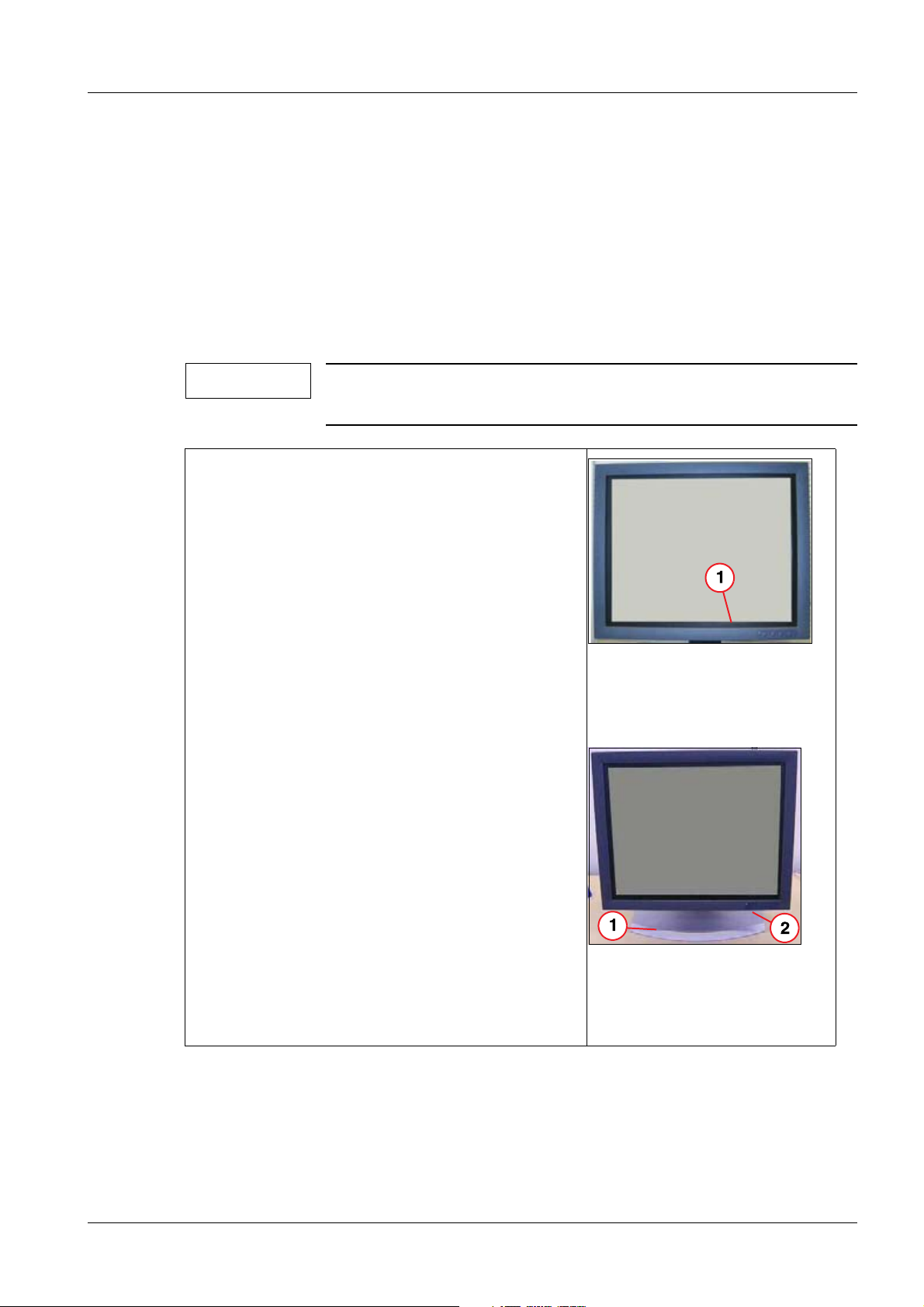
• The DSC 1703-DC-V (model designation) is a
high-resolution, 17” TFT color monitor (43 cm).
Shipment of the TFT monitor is always without
the base.
• For the “table mode”, an additional base is avail-
able.
• When used with the base, the “dark” rubber seal
is replaced by a silver rubber seal.
The silver rubber seal is part of the “base shipment”.
• OSD operation is performed using the push-but-
tons located at the bottom right of the front panel.
Fig. 1: DSC 1703-DC-V (front
without base)
Pos. 1 Plastic frame for adapting the
17” panel to the 18” housing
Fig. 2: DSC 1703-DC-V (front
Pos. 1 Base
Pos. 2 Power switch (behind front
Siemens AG TD00-000.841.13.04.02 Display
Medical Solutions
02.05 CS PS 213
Page 5 of 44
incl. base)
panel)
Page 6

6 General Information
Technical Data 0
Power Supply Voltage range => 100V to 240V, +/- 10%
Fine fuse => 2x 3.5 A quick-blow
Power line frequency => 47Hz to 63Hz
Power consumption => < 75W
Inputs DVI Socket (29-pole):
=> input for DVI analog signal or DVI digital signal.
Sub-D Socket (15-pole):
=> H/C synch input and V synch / RGB input.
Mini DIN Socket (4-pole):
=> S video input
BNC Socket:
=> BAS signal input
Analog Signal Level:
Video level: 0,5 ... 1.00 Vpp
Sync level: 0,2 ... 0.4 Vpp
Resolution max. 1280 x 1024 (format filling)
Background
Brightness
200 cd/m
Status when shipped: 137 cd/m
2
min, 250 cd/m2 typical
2
with use of the video norm: 1280 x
1024/75 Hz VESA
Contrast Ratio 400:1 min, 500:1 typical
Environment Transport and Storage (in original packaging):
Ambient temperature: -20 to +60°C
Temperature gradient <5°C/h
Relative humidity, max 75% at +25°C, no condensation.
Pressure 1040 to 674 hPa
Operation:
Ambient temperature: + 5 to + 35°C
Temperature gradient <5°C/h
Relative humidity, max 80% at +30°C, no condensation.
Pressure 1040 to 860 hPa
Installation Heat dissipation is achieved by “natural" convection; a fan is not
installed. The free setup height as well as the side and rear distance
must be at least 100 mm.
However, installation in the DCS is permitted.
Weight 5.7 kg, +/- 0.2
Display TD00-000.841.13.04.02 Siemens AG
02.05 CS PS 213
Page 6 of 44
Medical Solutions
Page 7

General Information 7
Pixel defects (dot = subpixel) Maximum Number
white dots 7
black dots 8
white and black dots 10
2 connected white dots 1
Siemens AG TD00-000.841.13.04.02 Display
Medical Solutions
02.05 CS PS 213
Page 7 of 44
Page 8

8 General Information
Repair / Troubleshooting 0
NOTE
• In a malfunction situation, the TFT monitor is only completely
replaced.
• With table application, the TFT monitor must be connected on
the base provided; the black rubber seal from the replacement
unit must be replaced with the silver one from the defective
unit.
The table base, incl. silver rubber seal can also be ordered as
replacement part.
• For replacement part numbers, see the SPC (Spare Parts Cata-
logue).
• Every defective monitor must be returned with an exact de-
scription of the malfunction. Without a description of the malfunction, it is virtually impossible to find sporadic and/or
temperature-related effects or even system-related causes.
• To adapt to the particular system, see (System-related
Adjustments / p. 20).
Display TD00-000.841.13.04.02 Siemens AG
02.05 CS PS 213
Page 8 of 44
Medical Solutions
Page 9

General Information 9
Test Equipment and Aids 0
• All required settings, see (System-related Adjustments / p. 20), must be performed us-
ing the push-buttons on the front of the unit.
• SMfit ACT luminous density meter See CB - DOC TD00-000.801.01... (Spare Parts
Catalogue).
Siemens AG TD00-000.841.13.04.02 Display
Medical Solutions
02.05 CS PS 213
Page 9 of 44
Page 10
10 General Information
General Remark Regarding Use of the OSD Menu 0
Button Functions 0
TFT Monitor, Part No. 30 99 959
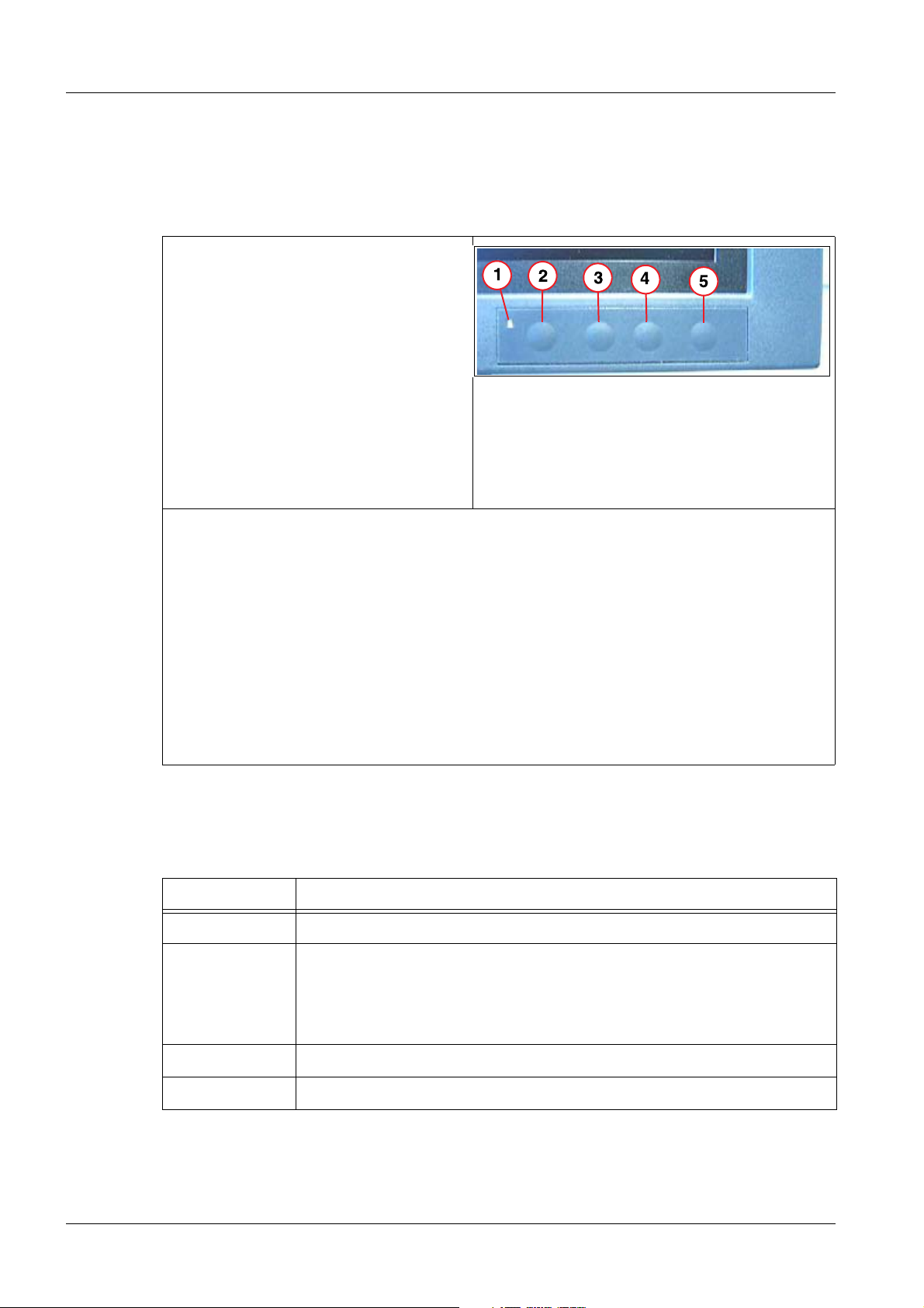
Fig. 3: DSC 1703 ..... (push buttons)
Pos. 1 Power LED
Pos. 2 Menu
Pos. 3 Up
Pos. 4 Down
Pos. 5 Set
• The status of the TFT monitor is displayed by the power LED. On / OFF / Standby.
• The front buttons are designed without a “designation”.
• All required adjustments are made using the push-buttons located on the front frame.
The push-buttons are blocked when shipped (new system).
• Unlocking or locking them is done as follows:
Press the SET button 1x.
Press the Up button 3x.
The OSD menu can then be selected using the Menu button.
• The OSD menu can also be started without an input signal.
OSD Menu 0
Tab. 1 Button functions in the OSD menu
Button(s) Action
Menu Selection of the OSD / menu item
up (+) Open the menu item, a sub menu can be recognized by the fact that
the meu title is highlighted. To open the Service Level 2 menu, see
(Tab.2/p.11).
Set the value up or to the right.
down (-) Set the value down or to the left.
Set Close the menu item (press one level higher 1x).
Display TD00-000.841.13.04.02 Siemens AG
02.05 CS PS 213
Page 10 of 44
Medical Solutions
Page 11

General Information 11
Tab. 2 Blocking/Unblocking the OSD Menu
Function Action
Press the Set button 1x and the Up button 3x.
OSD Menu
block or enable
Select
Service Level 2.
Adjustment Values
Save
The OSD may not be opened to block or to release the
OSD! If opened, first exit the OSD using “Undo”.
If the OSD is blocked, only switching the input signal
with the Up and Down buttons is possible.
Press the Up button 1x and the Down button 2x.
To get to the Service Level 2 menu, the following procedure is necessary:
• Select the OSD menu.
• Select Service Level 2 with the Menu button.
• Open the Service Level 2 menu by pressing the Up
button 1x and the Down button 2x.
In service level 2, expanded adjustments can be performed.
Press the “Set” button as often as required until the
“Undo” menu item appears.
Any changes made are accepted with “Accept
changes”.
The “new” settings are rejected with “Reject changes”.
Selection is made with the “Menu” button.
Execute is made with the “Up” button.
Siemens AG TD00-000.841.13.04.02 Display
Medical Solutions
02.05 CS PS 213
Page 11 of 44
Page 12
12 General Information
Tab. 3 OSD Menu
Menu
Brightness /
Brightness
Contrast
Contrast
Backlight
Color Selection => 2
Set user color not enabled
Position /
Zoom
H Position Adjustable
V-Position Adjustable
Zoom Selection => Fill Screen
Source Source selec-
tion
Auto Bright-
Auto functions
ness Contrast
(can only be
selected when
controlled via
the VGA
D-Sub).
Auto Position
Phase Frequency
Not required; selection is automatic
Use only if the monitor is completely incorrectly adjusted.
Finally, the adjustment must be performed
per (System-related Adjustments / p. 20)!
Use only if the monitor is completely incorrectly adjusted.
Finally, the adjustment must be performed
per (Size / Position / p. 20)!
Display TD00-000.841.13.04.02 Siemens AG
02.05 CS PS 213
Page 12 of 44
Medical Solutions
Page 13

General Information 13
Language Ger-
man/English
Frequency /
Phase
Sharpness Selection => 3
Others
OSD Settings If required, the position and the “transpar-
DPMS settings Selection On
Status Status display of the monitor (e.g. temp.,
Calibration For additional adjustments, selection, see
Service level 2
User Settings Factory set!
Selection => English
Can be adjusted, see (System-related
Adjustments / p. 20)
Active only if the FBAS and/or the S-Video
input is used.
ency” of the OSD menu can be set here.
operating hours......)
(OSD Menu / p. 10).
It is possible to return to the factory setting
under “Reset User settings” in this screen.
All adjustments (B/KC/Phase/Frequency)
must then be repeated!
Test and Reset “Reset to factory defaults” may not be used!
If selected, original parameters are downloaded.
Tolerance Factory set.
Others Factory set.
Only if required, the H image size can be
adjusted under ““H Scaler clip”.
Siemens AG TD00-000.841.13.04.02 Display
Medical Solutions
02.05 CS PS 213
Page 13 of 44
Page 14

14 Troubleshooting
2Troubleshooting
3-
Troubleshooting 0
• General:
Every defective TFT monitor must be replaced completely.
Fuses:
If a fuse is defective, the TFT monitor must be replaced. A fuse responds only if there is
an error (in the TFT monitor). Because of this, replacing a fuse is not reasonable.
• Troubleshooting:
Malfunction Possible Cause Solution
TFT monitor displays no
image, power LED is off.
TFT monitor displays no
image, power LED is on.
Unclear image, defects in
vertical lines
Other malfunctions (sporadic)
Fuse defective.
Power cable not plugged
in or line power missing.
No video/synchronous signal (cable or video
source).
Inputs incorrectly plugged
in, with a new installation.
Frequency and/or phase
incorrectly set.
Disturbances in the video
signal.
Plug-in connection(s)
loose.
1. Fuse okay, line power
present.
2. Replace the TFT monitor.
1. Video/synchronous signal
present.
2. Replace the TFT monitor.
1. For frequency / phase setting, see (System-related
Adjustments / p. 20).
2. Make sure that the video
signal has no disturbances.
3. Replace the TFT monitor.
1. Make sure that there is not
a “control problem” (line
power/video).
2. Replace the TFT monitor.
Display TD00-000.841.13.04.02 Siemens AG
02.05 CS PS 213
Page 14 of 44
Medical Solutions
Page 15

Troubleshooting 15
Malfunction Possible Cause Solution
Required contrast no
longer reached?
Uroskop Access Use:
No Endo image
BA signal is too low. 1. The BA signal must be at
least 0.5V, otherwise “full
control” is no longer ensured.
2. An B/C adjustment under
(Brightness /
Contrast / p. 21) makes no
improvement.
3. Replace the TFT monitor.
1. Make sure that the switch
signal is present at "For
Service and RS232 Bus" input.
- Switch the RS232 con-
nector to the "Live Monitor".
- Switch OK => replace the
monitor.
- Switching defective. Look
1. Control to switch the infor an error in the control.
put is missing (RS232).
2. Make sure that the S-video
2. Video signal missing at
signal is present.
the SVHS input.
- Switch the S-video connector to the "Live Monitor" (also RS232
switching).
- Image OK => replace the
monitor.
- Image not OK => look for
an error in the S-video
control.
Siemens AG TD00-000.841.13.04.02 Display
Medical Solutions
02.05 CS PS 213
Page 15 of 44
Page 16

16 Replacing the TFT Monitor
3Replacing the TFT Monitor
4-
Use 0
Table Application (Application with the Base) 0
Tab. 4 TFT monitor with stand
• In a replacement part situation, the TFT is always
shipped without the base.
• Open the back wall of the stand base (snap in), see
(Fig.4/p.16).
• Unplug the connection cable, see (2/Fig.5/p.16).
• Remove the TFT monitor from the stand base, see
(1/Fig.5/p.16).
• Install the replacement unit in the reverse order of the
steps above.
• Replace the existing rubber seal (black) on the re-
placement unit with the silver rubber seal from the defective unit, see (Fig.6/p.16).
• Perform adjustment per the application, see (Sys-
tem-related Adjustments / p. 20).
Note:
The “silver” rubber seal is part of the stand base shipment.
If the rubber seal is needed, a stand base must be
ordered as a replacement part, see the SPC.
Fig. 4: TFT monitor, open
base
Fig. 5: TFT monitor,
Vesa/cable
Pos. 1 Mounting screw (4x)
Pos. 2 Electrical connections
(power/video/ground)
Fig. 6: TFT monitor, rubber
seal
Display TD00-000.841.13.04.02 Siemens AG
02.05 CS PS 213
Page 16 of 44
Medical Solutions
Page 17

Replacing the TFT Monitor 17
Monitor Carriage 0
Tab. 5 TFT on Trolley
• Remove the rear cover panel (con-
nections).
• Unplug all electrical connections
(Pos. 2/3/4).
• Remove the TFT monitor, 4 screws,
Pos. 1.
• Install the replacement unit in the re-
verse order of the steps above.
• Perform adjustment per the applica-
tion, see (System-related
Adjustments / p. 20).
Fig. 7: DSC 1703-DC-V, trolley
Pos. 1 VESA adapter
Pos. 2 Ground connection
Pos. 3 Power connection
Pos. 4 VGA connection (D-sub)
Siemens AG TD00-000.841.13.04.02 Display
Medical Solutions
02.05 CS PS 213
Page 17 of 44
Page 18

18 Replacing the TFT Monitor
DCS Application 0
• Loosen the two screws on the cover panel (do not re-
move them).
• Pull the screws “forward” and remove the cover panel.
• Unplug the electrical connections.
• If the TFT monitor is operated in a six/three-unit ar-
rangement and a middle one fails, see also the following note regarding the 6-unit DCS.
Fig. 8: DCS, mechanical
connection
Pos. 2 screws for cover panel
• Caution, the TFT monitor will tilt forward!!
• Remove the 4 screws on the VESA adapter (connec-
tion from the TFT monitor to the DCS).
• Take the TFT monitor out of the DCS towards the front.
• Install the replacement unit in the reverse order of the
steps above.
Fig. 9: DCS - TFT
mechanical
connection
Pos. 4 screws for VESA
adapter
Note Regarding a 6-Unit DCS
• To make removing and installing the TFT monitor easier, an “outside” TFT monitor
must be disconnected and moved “out”.
See illustration!
• Then the middle TFT monitor can also be disconnected and moved “out”. Removal/in-
stallation is then performed “normally”.
Fig. 10: Moving the DCS - TFT monitor
Display TD00-000.841.13.04.02 Siemens AG
02.05 CS PS 213
Page 18 of 44
Medical Solutions
Page 19

Replacing the TFT Monitor 19
Support Arm Use (Uroskop Access) 0
• Open the rear cover panel.
• Disconnect all electrical connections,
Pos. 1/2/3/4/5.
• Remove the TFT monitor, 4 screws,
see Pos. 6.
• Install the replacement unit in the re-
verse sequence.
• Perform an adjustment per the applica-
tion, see (Uroskop Access / p. 36).
Fig. 11: Uroskop Access
Pos. 1 Power connector
Pos. 2 VGA connection (D-sub)
Pos. 3 Serial connector (system controller for video
input)
Pos. 4 S Video connector
Pos. 5 Ground connection
Pos. 6 Vesa Adapter
Siemens AG TD00-000.841.13.04.02 Display
Medical Solutions
02.05 CS PS 213
Page 19 of 44
Page 20

20 System-related Adjustments
4System-related Adjustments
5-
AX Area 0
NOTE
• All values listed, including the listed tolerances, are “setting
values”.
The listed tolerances are not values for the constancy check of
the display!
• OSD Operation:
For general remarks regarding operation of the OSD menu (release of operation, etc.), see (OSD Menu/p.10).
• Prior to beginning the adjustment, the monitor must be
switched on for approx. 20 min.
AXIOM Artis VCR Operation 0
• When it is switched on, the display detects the applied video norm and automatically
sets itself to it.
- New norms that have not yet been set must be set. The next time this norm is used,
the display sets the norm again automatically.
- There is separate set of parameters in the display for each norm. This means that
each norm used must be set individually! The backlight setting is the same for all
norms.
Size / Position
• Image position:
- Trigger fluoro and display an LIH image on the VCR-R monitor.
Fig. 12: VCR LIH, test image
Pos. 1 Image size, H - V
- OSD Menu => Position / Zoom =>
- V-Position:
For 60Hz, set the application to 30.
For 50 Hz, set the application to 20.
Display TD00-000.841.13.04.02 Siemens AG
02.05 CS PS 213
Page 20 of 44
Medical Solutions
Page 21

System-related Adjustments 21
NOTE
The values from the slider in the menu "Position / Zoom" are again
in the middle position after saving and again selecting the menu
(with connection via S-Video); in this way, the "Adjustment Range"
is expanded.
However the previously set value was accepted!
- OSD Menu => Others => Service Level 2 (to select Service Level 2, see
(Tab.2/p.11)).
Using “H - Scaler clip”. setH to V to the same amplitude (H amplitude can be
changed), see (1/Fig. 12 / p. 20).
- H- Position, required only with the 60 Hz application, with 50Hz, continue with the
next step.
OSD Menu => Position / Zoom =>
Set the slider for H-Position to “0“.
Exit OSD with Accept Changes.
Switch off the monitor, switch it back on.
OSD Menu => Position / Zoom =>
Set the slider for H-Position to “30“.
- Exit the OSD menu with “Accept Changes” (press the Set button until the “Undo”
menu is reached).
Or continue immediately with Brightness Contrast.
Brightness / Contrast
NOTE
The measurement is performed using the SMfit ACT meter; when
doing this, the influence of the ambient light must be excluded (by
covering the area around the measuring probe).
During the measurement, make sure that no pressure is exerted by
the measuring sensor on the panel surface; this can cause damage or to a failure of the panel.
Siemens AG TD00-000.841.13.04.02 Display
Medical Solutions
02.05 CS PS 213
Page 21 of 44
Page 22

22 System-related Adjustments
• Generating a Test Image
- Select the current organ program in the Editor (see illustration), not the DSA program!
- Position the center to "0".
Position the width to "1".
- Select "Apply", not Store(!!). In this way, the "old" values are again accepted by changing the program in
the Editor.
- Select "Close Editor".
Fig. 13: Editor
Pos. 1 Selecting the Editor
• Making a Recording
- Collimate with the collimator, see illustration.
- Trigger a brief exposure to display the image on the
monitor.
-
Fig. 14: VCR test image
• The brightness / contrast adjustment are made in: OSD main menu => Brightness /
Contrast.
- Set the slider for "Contrast" to maximum.
- Set the slider for "Brightness" to “ 30 “.
- Using the slider for "Backlight", set 137 cd/m
- Using the slider for "Brightness", set 0.45 cd/m
- Use the slider for “Contrast” to lower the contrast until the cd/m2 value in the white
area (measured with the SMFit meter) drops.
Then increase again using the slider until the previously set value (backlight value
from the table) is just reached again.
- Check the brightness value in the black area; if necessary, adjust it.
If it had to be “readjusted”, the contrast value must also be rechecked, and if
necessary, adjusted.
- Save the new adjustment values:
Press the Set button as often as needed until the “Quit OSD menu” appears. Select
“Accept changes”.
2
+15/-15 cd/m2 in the 100% field.
2
+0.15/-0.05 cd/m2 in the black field.
Display TD00-000.841.13.04.02 Siemens AG
02.05 CS PS 213
Page 22 of 44
Medical Solutions
Page 23

System-related Adjustments 23
- Switch the organ program at the AXIOM Artis and select it again; when this is done,
the Window changes are reset to the original ones.
- Make a brief X-ray recording (also on DVD-R).
Playback of the recording from the DVD recorder must be optically the same on the
monitor.
Blocking the OSD Menu Again
• Block the OSD menu again by pressing the combination "SET" 1 x and "Up" 3 x, see
(Button Functions / p. 10).
AXIOM Artis DVD Recorder Mode 0
NOTE
• The TFT monitor detects the video norm that is set after switch-
ing on power and sets itself automatically to it.
- New video norms that have not yet be set, must be set. The
next time this norm is applied, the TFT monitor automatically
assigns it again.
- A separate set of parameters exists in the TFT monitor for
each video norm. This means that each video norm used
must be set individually! However, the setting for the backlight is the same for all video norms.
• The DVD recorder is operated at the S-video input of the TFT
monitor.
General Settings
• OSD menu => Service Level 2 (for selection of Service Level 2, see (Tab. 2 / p. 11)) =>
User settings.
Performing a Reset of the User Settings
• To prevent color saturation in the image, the image is displayed in black / white; to do
this, perform the following setting:
- OSD menu => Others => video settings => saturation
- Set the slider to the "left stop".
- Press the Up button 5x until the slider makes a brief movement to the right (the slider
may not be at the left stop!).
Siemens AG TD00-000.841.13.04.02 Display
Medical Solutions
02.05 CS PS 213
Page 23 of 44
Page 24

24 System-related Adjustments
Size / Position
• Image Position:
- Trigger fluoro and display an LIH image on the DVD recorder monitor.
Fig. 15: VCR LIH, test image
Pos. 1 Image size, H - V
- OSD Menu => Position / Zoom =>
- V - Position:
With use of 60 Hz, set to 30.
With use of 50 Hz, set to 20.
NOTE
The values from the slider in the "Position / Zoom" menu are again
in the middle position after saving and again selecting the menu
(with connection via S-Video as with VCR mode); this way, the "Adjustment Range" is expanded.
However the previously set value was accepted!
- OSD Menu => Others => Service Level 2 (to select Service Level 2, see
(Tab.2/p.11)).
Use “H Scaler clip” to set H to V at same Amplitude (H-Amplitude can be changed),
see (1/Fig. 15 / p. 24).
- H- Position, required only with 60 Hz use, for 50Hz continue with the next step.
OSD Menu => Position / Zoom =>
Set the slider for H-position to "0".
Exit OSD with Accept Changes.
Switch off the monitor and switch it back on.
OSD Menu => Position / Zoom =>
Set the slider for H-position to "30".
- Exit the OSD menu with “Accept Changes” (press sthe Set button until the “Undo”
menu is reached).
Or continue immediately with Brightness, Contrast.
Display TD00-000.841.13.04.02 Siemens AG
02.05 CS PS 213
Page 24 of 44
Medical Solutions
Page 25

System-related Adjustments 25
Brightness / Contrast
NOTE
The measurement is made using the SMfit test meter; here, the influence of the ambient brightness must be excluded (by covering
the area around the measuring sensor).
When making the measurement, make sure that the measuring
sensor does not exert any pressure on the panel surface; this can
cause the panel to be damaged or to fail.
• Generate a test image:
- Select a current organ program (not DSA!).
Set the Center to “0“.
Set With to “1“.
“ Select Apply”, not Store (!!). When this is done, the "old" values are again accepted
by switching selection of the organ program.
“ Select Close Editor“.
- Collimate with the collimator, see illustration:
Fig. 16: VCR test image
- Trigger a brief exposure and make a DVD recording.
- Play back the VCR, select Play and Pause (image is displayed on the TFT monitor).
- Play back the recorded VCR test image with Play and Pause.
• Brightness / Contrast adjustments are made under: OSD main menu => Brightness /
Contrast.
- Set the slider for "Contrast" to maximum.
- Set the slider for "Brightness" to “ 30 “.
- Use the slider for "Backlight" to set 137 cd/m
- Use the slider for "Brightness" to set 0.45 cd/m
field.
- Lower the slider for “Contrast” until the cd/m2 value in the white field (measured with
the SMFit meter) drops.
Again increase the slider until the previously set value is just reached.
- Check the brightness value in the black field, adjust it if required.
If it needed to be "readjusted", the contrast value must again be checked, and if
needed, adjusted.
- Saving the new adjustment values:
Press the Set button until the “Quit OSD menu” appears. Select “Accept changes”.
2
+15/-15 cd/m2 in the 100% field.
2
+0.15/-0.05 cd/m2 in the black
Siemens AG TD00-000.841.13.04.02 Display
Medical Solutions
02.05 CS PS 213
Page 25 of 44
Page 26

26 System-related Adjustments
- Change the organ program at the AXIOM Artis and select it again; when this is done,
the Window changes are again set back to their original settings.
Blocking the OSD Menu again
• Block the OSD main menu again by pressing the combination of "SET" 1x and "Up" 3x,
see (Button Functions / p. 10).
Cathcor 0
• When it is switched on, the display detects the applied video norm and automatically
sets itself to it.
- New norms that have not yet been set must be set. The next time this norm is applied, the display automatically sets itself to the norm.
• Prior to beginning the adjustment, the monitor must be switched on for approx. 20 min.
Selecting the OSD Menu
For start and operation, see (OSD Menu/p.10).
Adjustment / Configuration
NOTE
• Currently, a “test image” cannot be started or made available
on the Cathcor.
Because of this, “default values” are defined for all relevant
settings.
• If other values are required for IQ or system-technical reasons,
it is permissible to differ from these default values.
Only the value for “Backlight” should not be increased above
the default value for reasons related to wear!
• For technical reasons, the display is not suitable for a sweep
speed of 100 or can be only with significant quality restrictions.
• Reset user settings (reset to “values when shipped”):
A reset of the user settings must be performed only if the adjustment does not produce
the correct results!
- Under: Service level 2 (to select Service Level 2, see (Tab.2/p.11) ) => User set-
tings => Reset User Settings
preform a reset of the user settings.
• In the OSD menu under Brightness / Contrast =>
- set the Brightness to 55.
- set the Contrast to 70.
- set the Backlight to 80.
Display TD00-000.841.13.04.02 Siemens AG
02.05 CS PS 213
Page 26 of 44
Medical Solutions
Page 27

System-related Adjustments 27
• In the OSD menu under Others =>
-set Frequency / Phase => Frequency to 1472, Phase to 90.
NOTE
-set Sharpness => to 5.
With Frequency / Phase, the most frequently used sweep speed
can be optimized as regards streaks.
• In the OSD menu, under: Service Level 2 (to select Service Level 2, see (Tab. 2 / p. 11)
) => Calibration =>
-set Select Display function => to 1 (specified factory adjustment).
• If the image position (horizontal and/or vertical is not correctly displayed, it must be cor-
rected in the OSD menu under Position / Zoom.
• Save the new adjustment values:
Press the Set button as often as needed until the “Quit OSD menu” appears. Select
“Accept changes”.
Blocking the OSD Menu Again
• Block the OSD menu again by pressing the combination "SET" 1 x and "Up" 3 x, see
(Button Functions / p. 10).
ICONOS R100.. / R200 ND 0
• When it is switched on, the display detects the applied video norm and automatically
sets itself to it.
- New norms that have not yet been set must be set. The next time this norm is applied, the display automatically sets itself to the norm.
• Prior to beginning the adjustment, the monitor must be switched on for approx. 20 min.
Selecting the OSD Menu
For start and operation, see (General Remark Regarding Use of the OSD Menu / p. 10).
Adjustment / Configuration
NOTE
• To ensure IQ, the adjustment must be performed in the follow-
ing sequence.
• The Auto adjust / Reset of user settings may not be performed
with the DIC test image; “only” the normal DIC image may be
present.
Siemens AG TD00-000.841.13.04.02 Display
Medical Solutions
02.05 CS PS 213
Page 27 of 44
Page 28

28 System-related Adjustments
• Reset user settings (reset to “values when shipped”):
- A reset of the user settings must be performed only if the adjustment does not produce the correct results!
Under: Service level 2 (to select Service Level 2, see (Tab.2/p.11)) => User
settings => Reset user settings.
perform a reset of the user settings.
Note: When this is done, the image display appears green (not an error).
• Configuration:
- Under: Service level 2 (to select Service Level 2, see (Tab.2/p.11) ) => Others =>
set Signal to Monochrome.
- In the OSD menu, under: Service Level 2 (to select Service Level 2, see
(Tab.2/p.11) ) => Calibration =>
Select Display function =>
Up to/including Serial Number ...... 001388 set to “2” (specified factory setting,
Gamma curve).
Beginning with Serial Number .....001389 set to “ 3 “
If a unit with Serial Numbers < ...001389 was ordered from the E warehouse, set to “
3 “ , these units have been changed by the supplier!
• Brightness / Contrast Adjustment
NOTE
NOTE
The measurement is performed using the SMfit ACT meter; when
doing this, the influence of the ambient light must be excluded (by
covering the area around the measuring probe).
During the measurement, make sure that no pressure is exerted by
the measuring sensor on the panel surface; this can cause damage or to a failure of the panel.
Contrast:
Detection of the 95% fields in the 100% field (limitation) is adjusted
using video gain (contrast).
Backlight:
The 100% field (maximum white) is adjusted using the backlight.
Brightness:
Adjustment of the black area (basic brightness and detection of
the 5% field).
Display TD00-000.841.13.04.02 Siemens AG
02.05 CS PS 213
Page 28 of 44
Medical Solutions
Page 29

System-related Adjustments 29
Select the black / white text image on the
Videomed DIC:
• Videomed DIC
set the S2 - 3 / 4 / 5 / 5 switch to the On position.
• Press the S1 push button until the black /
white test image is displayed on the TFT
monitor.
- The adjustment is performed under: OSD Menu => Brightness / Contrast.
- Set the slider for Brightness to the minimum.
- Set the slider for Contrast to the maximum.
- "1" Use the slider for Backlight to set 160 cd/m
- "2" Use the slider for Brightness to set 0.5 cd/m
- “3” Lower the slider for Contrast until the 95% field is visible.
- “Alternately repeat adjustments 1, 2 and 3” until the specified values are reached.
- Set the adjustment value under Double Contrast (e.g. current value = 30 to 60). The
95% field is not longer visible.
Note: If the value cannot be doubled (the adjustment value is > 50), the slider for
contrast is set to the maximum.
- Using the slider for Brightness, set 0.5 cd/m
- Save the new adjustment values:
Press the Set button as often as needed until the “Quit OSD menu” appears. Select
“Accept changes”.
Fig. 17: Videoemd DIC B/W test image
Pos. 1 White field (100% white)
Pos. 2 Black field (0% white)
Pos. 3 5% field
Pos. 4 95% field
2 +
/-10 cd/m2 in the 100% field.
2 +
/- 0.2 cd/m2 in the black field.
2 +
/- 0.2 cd/m2 in the black field.
• Block the OSD menu again by pressing the combination "SET" 1 x and "Up" 3 x.
• Switch off the test image in the Videomed DIC:
Set the Videomed DIC S2 - 3 / 4 / 5 / 6 switch to the Off position.
Press the S1 push button; there will be a reset and the “normal” image will be displayed
again.
Siemens AG TD00-000.841.13.04.02 Display
Medical Solutions
02.05 CS PS 213
Page 29 of 44
Page 30

30 System-related Adjustments
NOTE
• The best possible IQ is ensured by this Brightness/Contrast ad-
justment.
• If the customer complains about “cutoffs“ in bright areas, the
contrast can be set lower. In this way, cutoffs are minimized.
However, in this case, the image is displayed with lowered contrast!
Display TD00-000.841.13.04.02 Siemens AG
02.05 CS PS 213
Page 30 of 44
Medical Solutions
Page 31

System-related Adjustments 31
SP Department 0
SIREMOBIL Compact / L / Iso-C 0
NOTE
• All values listed, including the listed tolerances, are “setting
values”.
The listed tolerances are not values for the constancy check of
the display!
• OSD Operation:
For general remarks regarding operation of the OSD menu (release of operation, etc.), see (OSD Menu/p.10).
• Prior to beginning the adjustment, the monitor must be
switched on for approx. 20 min.
• The TFT monitor on the Siremobil .... is controlled via the VGA
(D-sub) input.
Requirements
The basic unit and the monitor cart are connected to each other; the system is fully functional.
Memoskop Programming
NOTE
• Memoskop programming is not required "only" for the TFT
monitor replacement (already programmed) ==> continue with
(Programming at the TFT Monitor / p. 31).
• Flicker-free display is possible with the TFT monitors, even at
50 Hz / 60 Hz.
• The video frequency on the MEMOSKOP must therefore be set
to the video frequency of the VIDEOMED DC camera.
• Start the Technical Setup on the MEMOSKOP (CTRL + T) and enter the password.
• Select the “2. Video frequency“ menu.
- With 50 Hz, set the VIDEOMED DC camera to 50 Hz and save by pressing the “Return” button.
- With 60 Hz, set the VIDEOMED DC camera to 60 Hz and save by pressing the “Return” button.
• Exit the Technical Setup by pressing the “HOME“ button [>Ι<].
Programming at the TFT Monitor
• Open the OSD, to select it, see (Tab.2/p.11).
Siemens AG TD00-000.841.13.04.02 Display
Medical Solutions
02.05 CS PS 213
Page 31 of 44
Page 32

32 System-related Adjustments
• Service level 2 (to select Service Level 2, see (Tab.2/p.11) ) => Tolerance.
- Under “Norm group“ => select “Memoskop“, exit the menu with “Set”.
• Service level 2 (to select Service Level 2, see (Tab.2/p.11) ) => Others, exit the
menu with "Set".
- Under “Signal“ => select “Monochrome“, exit the menu with “Set”.
• Service level 2 (to select Service Level 2, see (Tab.2/p.11) ) => User Settings => se-
lect Reset User Settings with the “Up” key.
(with this procedure, the "Memoskop Norm" is reliably detected).
Checking / Adjusting Brightness, Contrast and Geometry with Camera Synchronization
• Select "User Setup" at the MEMOSKOP.
• Select the SMPTE test pattern, close the User
Setup again with the "Home" button.
• Select LUT 1 for both TFT monitors.
Fig. 18: MEMOSKOP SMPTE test
pattern
Display TD00-000.841.13.04.02 Siemens AG
02.05 CS PS 213
Page 32 of 44
Medical Solutions
Page 33

System-related Adjustments 33
Tab. 6 TFT Adjustment
• Check:
- Measurement values:
0% field = 0.45 cd/m. +/- 0.1 cd/m
100% field => 137cd/m, +/- 10cd/m
The 5% field and the 95% field must be detectable.
If the measurement values are not reached or if the fields cannot be detected, per-
form an adjustment.
• Brightness / Contrast Adjustment:
- The adjustment is performed under: OSD Menu => Brightness / Contrast.
- Set the slider for Brightness to the minimum.
- Set the slider for Contrast to the maximum.
- “1” Using the slider for Backlight, set 137 cd/m
- “2” Using the slider for Brightness, set 0.45 cd/m
- “3” Lower the slider for Contrast until the 95 % field is still just visible.
- “Alternately repeat adjustments 1, 2 and 3” until the specified values are
reached.
- The 5% field and the 95% field must be detectable.
- Press the button until Accept changes is selected. Save the adjustment values with
the "Up" key.
2 +
/-10 cd/m2 in the 100% field.
2 +
/- 0.1 cd/m2 in the black field.
• Image Geometry:
- The SMPTE test pattern must be displayed.
- The image geometry must correspond to the illustration (Fig. 18 / p. 32).
- The center vertical and horizontal lines in the SMPTE test pattern must be detectable. If there are differences, the image geometry must be corrected.
Siemens AG TD00-000.841.13.04.02 Display
Medical Solutions
02.05 CS PS 213
Page 33 of 44
Page 34

34 System-related Adjustments
Checking / Adjusting Brightness, Contrast and Geometry in the "Stand Alone" Mode (Memoskop)
• Disconnect the monitor cart from the basic
unit, unplug the X10 connector.
• Select "User Setup" at the MEMOSKOP.
• Select the SMPTE test pattern, close the
User Setup again with the "Home" button.
• Select LUT 1 for both TFT monitors.
Fig. 19: MEMOSKOP SMPTE test
pattern
Display TD00-000.841.13.04.02 Siemens AG
02.05 CS PS 213
Page 34 of 44
Medical Solutions
Page 35

System-related Adjustments 35
Tab. 7 TFT Adjustment
• Check:
- Measurement values:
0% field = 0.45 cd/m, +/-0.1 cd/m
100% field => 137cd/m, +/- 10cd/m
The 5% field and the 95% field must be detectable.
If the measurement values are not reached or if the fields are not detectable, per-
form an adjustment.
Note:
Adjustment of the “Backlight” has already been performed with “Camera Synchronization” and may not be changed. A change in this “mode” will alos cause a change in the
adjustment of the “Camera Synchronization”.
Backlight adjustment can be performed only once for all configured modes.
• Brightness / Contrast Adjustment:
- The adjustment is performed under: OSD Menu => Brightness / Contrast.
- Set the slider for Contrast to maximum.
- Use the slider for Brightness to set 0.45 cd/m
- Lower the slider for Contrast until the 95% field is just visible.
- “Alternately repeat” the adjustment until the specified vales are reached.
- The 5% field and the 95% field must be detectable.
- Control measurement: In the 100% field, 137 cd/m
If the value is not maintained, repeat the adjustment beginning from (Checking /
Adjusting Brightness, Contrast and Geometry with Camera
Synchronization / p. 32).
- Press the button until Accept changes is selected. Save the adjustment values with
the "Up" key.
2 +
/- 0.1 cd/m2 in the black field.
2 +
/- 10 cd/m2 must result.
• Image Geometry:
- The SMPTE test pattern must be displayed.
- The image geometry must correspond to the illustration (Fig. 19 / p. 34).
- The center vertical and horizontal lines in the SMPTE test pattern must be detectable. If there are differences, the image geometry must be corrected.
Siemens AG TD00-000.841.13.04.02 Display
Medical Solutions
02.05 CS PS 213
Page 35 of 44
Page 36

36 System-related Adjustments
Uroskop Access 0
NOTE
• The DSC 1703-DC-V (Material Number 30 99 959) is used wi9th
the Uroskop Access as a Live and Reference monitor on the
TFT support arm (version beginning 01/2005; Material Number
77 57 565).
• All values listed, including the listed tolerances, are setting
values”.
The listed tolerances are not values for the constancy check of
the display!
• OSD Operation:
For general remarks regarding operation of the OSD menu (release of operation, etc.), see (OSD Menu/p.10).
• Prior to beginning the adjustment, the monitor must be
switched on for approx. 20 min.
• The last adjustment values are noted in the chapter (Adjust-
ment Values/p.42).
Size / Position
NOTE
• The screen display must be "display filling". If this is not the
case, the size and position must be adjusted manually.
• The image position has to be centered to the dispslay frame.
The white edge and/or the contour of the on-screen legend
have to be visible at all display edges. Information cannot be
truncated.
Display TD00-000.841.13.04.02 Siemens AG
02.05 CS PS 213
Page 36 of 44
Medical Solutions
Page 37

System-related Adjustments 37
• For the adjustment, download the
“EXP_TestbildExposure” from the local database (Fig. 20 / p. 37) in the Patient List
under “IQ Test Images” to the Viewer
(Fig. 21 / p. 37) and display the test image
on the particular monitor.
Fig. 20: SMPTE test pattern
• Select the OSD menu (to select it, see
(Tab.2/p.11)) with the Menu” button.
• Select the "Position/Zoom" menu with the
"Menu" button and press the "Up" key 1x.
• Adjust the image position using the "H posi-
tion" and "V position" sliders (change the
setting values with the "Up" and "Down"
keys).
• Select the "Zoom" menu item with the
"Menu" button and "1:1" with the "Up" key.
• Press the "Set" key until the menu with the
selection "Accept Changes: and "Reject
Changes" appears.
• Save the settings that were made by press-
ing the "Up" key with the "Accept Changes"
menu point selected.
Brightness / Contrast
NOTE
• Adjustment of the brightness and backlight is made usinghte
SMFit test meter, for the setting values, see the document "Image Quality Quick Test" (document number SPL5-330.820), sub
chapter "Monitor Check".
Fig. 21: EXP_test pattern exposure
When performing the measurement, make sure that the measuring sensor does not exert any pressure on the panel surface.
• The OSD menu is used to set the brightness, backlight, and
contrast.
Siemens AG TD00-000.841.13.04.02 Display
Medical Solutions
02.05 CS PS 213
Page 37 of 44
Page 38

38 System-related Adjustments
• For the adjustment, download the (Fig. 21 / p. 37) test image from the local database in
the Patient List under “IQ Test Images” (Fig. 20 / p. 37) to the Viewer (Fig. 21 / p. 37)
and display the test image on the particular monitor.
• Call the OSD menu with the "menu" key.
- The menu item "brightness/contrast" is selected automatically.
• Press the "up" key once (1x).
• Adjust the brightness, contrast and backlight with the sliders (change the setting values
with the "up" or "down" key) as described.
• Adjust the basic brightness in the 0% field using the slider for brightness to the value
specified in the IQ Quick Test (document number SPL5-330.820..).
• Increase the contrast with the slider for contrast to the max. Move the contrast value
back so that the 95% field is just still detectable.
• Adjust the basic brightness in the 100% field using the slider for backlight to the value
specified in the IQ Quick Test (document number SPL5-330.820..).
• If needed, repeat the adjustment procedure (0% field and 95% field).
• The 5% field and the 95 % field must be detectable.
NOTE
Frequency/phase
NOTE
The adjustment of "backlight" that is made here remains applicable for all signal sources because with this monitor mode, it is not
possible to save a second configuration for "backlight".
The frequency and phase settings must be corrected manually.
• For the adjustment, download the (Fig. 21 / p. 37) test image from the local database in
the Patient List under “IQ Test Images” (Fig. 20 / p. 37) to the Viewer (Fig. 21 / p. 37)
and display the test image on the particular monitor.
• Call the OSD menu with the "menu" key.
- The menu item "brightness/contrast" is selected automatically.
• Use the "menu" key to select the menu item "Additional".
• Press the "up" key once (1x).
- The menu item "brightness/contrast" is selected automatically.
• Adjust the image position with sliders "H position" and "V position" (change the setting
values with the "up" or "down" key).
• Press the "Set" key until the menu appears that let's you select "accept changes" and
"reject changes".
• Store the settings performed by pressing the "up" key when in the menu item "accept
changes."
Display TD00-000.841.13.04.02 Siemens AG
02.05 CS PS 213
Page 38 of 44
Medical Solutions
Page 39

System-related Adjustments 39
NOTE
Color setting
All vertical lines in the image center have to be visible in the
SMPTE test image. Additionally, the eight-line grey wedge has to
be visible in the upper part of the image without shading. The entire test image must be free of moire structures or artifacts.
• Call the OSD menu with the "menu" key.
- The menu item "brightness/contrast" is selected automatically.
• Press the "up" key once (1x).
• Select menu item "color" with the menu key as well as the "up" key "2".
• Press the "Set" key until the menu appears that let's you select "accept changes" and
"reject changes".
• Store the settings performed by pressing the "up" key when in the menu item "accept
changes."
Adjusting "Force S-Video"
• Call the OSD menu with the "menu" key.
- The menu item "brightness/contrast" is selected automatically.
• Select the "Service Level 2" menu in the OSD menu (to select Service Level 2, see
(Tab.2/p.11)).
• Select the "Additional" menu item with the menu key. Press the "up" key once (1 x).
• Use the "menu" key to select the menu item "enforce S video".
• Select "on" with the "up" key.
• Press the "Set" key until the menu appears that let's you select "accept changes" and
"reject changes".
• Store the settings performed by pressing the "up" key when in the menu item "accept
changes."
DPMS setting
• Call the OSD menu with the "menu" key.
- The menu item "brightness/contrast" is selected automatically.
• Select the "Additional" menu item with the menu key. Press the "up" key once (1 x).
• Select the "DPMS setting" menu item with the "menu" key. Press the "up" key once (1
x).
• Select "on" with the "up" key.
• Press the "Set" key until the menu appears that let's you select "accept changes" and
"reject changes".
• Store the settings performed by pressing the "up" key when in the menu item "accept
changes."
Siemens AG TD00-000.841.13.04.02 Display
Medical Solutions
02.05 CS PS 213
Page 39 of 44
Page 40

40 System-related Adjustments
Settings for endoscopy (option: only at the reference monitor).
NOTE
• When replacing display DSC 1703-DC-V as reference monitor,
the following settings/tests have to be performed if the endoscopy interface exists.
• For additional test you require the operating instructions for
the endoscopy light source and the endoscopy camera unit (is
on-site at the customer's facilities).
• For the settings described in what follows the video signal has
to be present at the input of the endoscopy interface. It also
should be able to display it at the reference monitor on the TFT
support arm by using the "Endo US Ref" key at the table control panel of the system.
• If changes in image position are performed in the video mode
(the video signal is present at the input of the endoscopy interface), these changes are usually saved. When exiting the menu,
the "reject changes" menu is not in effect.
• When saving the minimum value for color saturation in the vid-
eo mode, this value is not saved. The 50% default value is automatically selected when switching off/on the monitor.
• Changes of the adjustment value for the backlight cannot be
performed when setting the endoscopy image.
Adjusting Brightness
• Test to see whether the camera unit is set to automatic operation (that is, the light
source regulates the level of lighting as a function of the environment illuminated by the
endoscope).
• Verify the video connection between camera unit and light source.
• Remove the flexible or rigid component at the endoscope guided by the physician into
the patient. Additionally, darken the camera head completely.
- The reference image appears completely dark.
• Use the SMFit measurement device to measure the luminance in the black display on
the reference monitor.
Display TD00-000.841.13.04.02 Siemens AG
02.05 CS PS 213
Page 40 of 44
Medical Solutions
Page 41

System-related Adjustments 41
• The measurement value must be 0.45 cd/m2 (+ 0.15/- 0.5 cd/m2).
- Adjustment: Select the OSD menu with the "Menu” button.
- The "Brightness / Contrast" menu item is selected automatically.
- Press the "Up button" 1x.
- Use the slider for brightness to adjust to 0.45 cd/m2 (+ 0.15/- 0.05 cd/m2).
- Set the slider for contrast to the maximum.
- Shine the light from a flashlight directly into the camera head (to generate an image
that is as white as possible).
- Lower the slider for contrast until the white value measued with the SMFit drops.
- Incrase the slider for contrast again until the measurement value is slightly below the
previously measured max. value.
NOTE
• Upon customer request, the black display setting can be set to
max. 1 cd/m2 via the brightness.
Color setting
• Call the OSD menu with the "menu" key.
- The menu item "brightness/contrast" is selected automatically.
• Press the "up" key once (1x).
• Select menu item "color" with the menu key as well as the "up" or "down" key "3".
• Press the "Set" key until the menu appears that let's you select "accept changes" and
"reject changes".
• Store the settings performed by pressing the "up" key when in the menu item "accept
changes."
NOTE
NOTE
If the customer wishes a color impression that is slightly higher
than the Color 3 recommended here, perform a customer-specific
color setting as described below.
The following table values should be viewed as a recommended
and can be adapted to conform to the customer's request.
• Call the OSD menu with the "menu" key.
- The menu item "brightness/contrast" is selected automatically.
• Press the "up" key once (1x).
• Select menu item "color" with the menu key as well as the "up" or "down" key "User".
• Select the "Setting the user color" menu with the "menu" key. Go the sub-menu with the
"up" key.
Siemens AG TD00-000.841.13.04.02 Display
Medical Solutions
02.05 CS PS 213
Page 41 of 44
Page 42

42 System-related Adjustments
• Set the following default values with the slider:
- Color temperature RED==> 3
- Color temperature GREEN==> 0
- Color temperature BLUE==> -3
• Press the "Set" key until the menu appears that let's you select "accept changes" and
"reject changes".
• Store the settings performed by pressing the "up" key when in the menu item "accept
changes."
Live and Reference Monitor Color Adaptations
If the Live and Reference monitors are color-adjusted to each other, the Live monitor must
be adjusted to the Reference monitor as follows.
• Peform the "User" adjustment in the "Brightness / Contrast - Color" menu.
• Then select the "Brightness / Contrast" menu user color with the Up key. Then perform
the color adaptation in the menu that is displayed.
Color saturation
NOTE
Change the color saturation only upon customer request.
• Call the OSD menu with the "menu" key.
- The menu item "brightness/contrast" is selected automatically.
• Select the "Additional" menu item with the menu key. Press the "up" key once (1 x).
• Use the "menu" key and select the menu item "vidoe setting>" Set the colo saturation
requested by the customer at the slider "color saturation." Use the "up" or "down" key.
• Press the "Set" key until the menu appears that let's you select "accept changes" and
"reject changes".
• Store the settings performed by pressing the "up" key when in the menu item "accept
changes."
Adjustment Values
NOTE
Make a note of the values that are to be set for the customer system in the following table.
Tab. 8 Adjustment Values:
Parameters Adjustment value.
Adjustment using SMPTE test image
H-Position
V-Position
Display TD00-000.841.13.04.02 Siemens AG
02.05 CS PS 213
Page 42 of 44
Medical Solutions
Page 43

System-related Adjustments 43
Parameters Adjustment value.
Zoom (default 1.1)
Brightness
Contrast
Backlight
Frequency
Phase
Color (default: 2)
Color Saturation
Induced S - Video (default: On)
DPMS (default: Off)
Adjusting the Endo image at the reference monitor
Window
Color (default: 3)
RED color temperature (if a cusomer-specific
color setting is wished).
GREEN color temperature (if a cusomer-specific color setting is wished).
BLUE color temperature (if a cusomer-specific color setting is wished).
Color saturation
Zoom (default: filling)
Siemens AG TD00-000.841.13.04.02 Display
Medical Solutions
02.05 CS PS 213
Page 43 of 44
Page 44

44 Changes to Previous Version
5Changes to Previous Version
6-
• Under “Replacing the TFT Monitor:
Support Arm application (Uroskop Access) => new.
• Under System-specific Adjustments:
Chapter "SIREMOBIL Compact / L / Iso-C" => changed.
Chapter "Uroksop Access" => new.
Chapter "AXIOM Artis DVD-R Mode" => new.
Chapter "ICONOS R100../ R200 ND" => changed.
Display TD00-000.841.13.04.02 Siemens AG
02.05 CS PS 213
Page 44 of 44
Medical Solutions
 Loading...