

Page 1
s
TC65 JAVA User's Guide
Siemens Cellular Engine
Version: 01
DocID: TC65 JAVA User's Guide_V01
JAVA™ Users Guide
Page 2

TC65 JAVA User's Guide
s
Strictly confidential / Draft
Document Name:
Version:
Date:
DocId:
Status:
TC65 JAVA User's Guide
01
March 11, 2005
TC65 JAVA User's Guide_V01
Strictly confidential / Draft
General Notes
Product is deemed accepted by recipient and is provided without interface to recipient’s products. The
documentation and/or product are provided for testing, evaluation, integration and information
purposes. The documentation and/or product are provided on an “as is” basis only and may contain
deficiencies or inadequacies. The documentation and/or product are provided without warranty of any
kind, express or implied. To the maximum extent permitted by applicable law, Siemens further
disclaims all warranties, including without limitation any implied warranties of merchantability,
completeness, fitness for a particular purpose and non-infringement of third-party rights. The entire
risk arising out of the use or performance of the product and documentation remains with recipient.
This product is not intended for use in life support appliances, devices or systems where a malfunction
of the product can reasonably be expected to result in personal injury. Applications incorporating the
described product must be designed to be in accordance with the technical specifications provided in
these guidelines. Failure to comply with any of the required procedures can result in malfunctions or
serious discrepancies in results. Furthermore, all safety instructions regarding the use of mobile
technical systems, including GSM products, which also apply to cellular phones must be followed.
Siemens or its suppliers shall, regardless of any legal theory upon which the claim is based, not be
liable for any consequential, incidental, direct, indirect, punitive or other damages whatsoever
(including, without limitation, damages for loss of business profits, business interruption, loss of
business information or data, or other pecuniary loss) arising out the use of or inability to use the
documentation and/or product, even if Siemens has been advised of the possibility of such damages.
The foregoing limitations of liability shall not apply in case of mandatory liability, e.g. under the
German Product Liability Act, in case of intent, gross negligence, injury of life, body or health, or
breach of a condition which goes to the root of the contract. However, claims for damages arising from
a breach of a condition, which goes to the root of the contract, shall be limited to the foreseeable
damage, which is intrinsic to the contract, unless caused by intent or gross negligence or based on
liability for injury of life, body or health. The above provision does not imply a change on the burden of
proof to the detriment of the recipient. Subject to change without notice at any time. The interpretation
of this general note shall be governed and construed according to German law without reference to
any other substantive law.
Copyright
Transmittal, reproduction, dissemination and/or editing of this document as well as utilization of its
contents and communication thereof to others without express authorization are prohibited. Offenders
will be held liable for payment of damages. All rights created by patent grant or registration of a utility
model or design patent are reserved.
Copyright © Siemens AG 2005
Trademark notices
MS Windows® is a registered trademark of Microsoft Corporation.
Java™
Borland® JBuilder® is a registered trademark of Borland Software Corporation
and Sun™ Java Studio Mobility 6 2004Q3 are registered trademarks of Sun Microsystems Inc.
TC65 JAVA User's Guide_V01 Page 2 of 69 11.03.2005
Page 3

TC65 JAVA User's Guide
Strictly confidential / Draft
s
Table of Contents
1 Preamble........................................................................................................................8
2 Overview ........................................................................................................................9
2.1 Related Documents ...............................................................................................9
2.2 Terms and Abbreviations.....................................................................................10
3 Installation ...................................................................................................................11
3.1 System Requirements .........................................................................................11
3.2 Installation CD .....................................................................................................11
3.2.1 Components...........................................................................................12
3.2.1.1 Module Exchange Suite ....................................................................12
3.2.1.2 WTK ..................................................................................................12
3.2.1.3 AT Java Open Framework (AJOF)....................................................12
3.2.1.4 Network Applications.........................................................................12
3.3 SMTK Installation.................................................................................................13
3.3.1 Installing the Standard Development Toolkit .........................................13
3.3.2 Installing the SMTK Environment...........................................................13
3.3.3 Installing Sun Java Studio Mobility 6 .....................................................14
3.3.4 Installing Eclipse 3.0 ..............................................................................14
3.3.5 Installing Borland JBuilder 9, X and 2005..............................................14
3.4 SMTK Uninstall ....................................................................................................15
3.5 Upgrades .............................................................................................................15
4 Software Platform .......................................................................................................16
4.1 Software Architecture ..........................................................................................16
4.2 Interfaces .............................................................................................................17
4.2.1 ASC0 - Serial Device .............................................................................17
4.2.2 General Purpose I/O..............................................................................17
4.2.3 DAC/ADC...............................................................................................17
4.2.4 ASC1......................................................................................................17
4.2.5 Digital Audio Interface (DAI) ..................................................................17
4.2.6 I2C/SPI...................................................................................................17
4.2.7 JVM Interfaces.......................................................................................18
4.2.7.1 IP Networking....................................................................................18
4.2.7.2 Media ................................................................................................18
4.2.7.3 Others ...............................................................................................18
4.3 Data Flow of a Java Application Running on the Module ....................................19
4.4 Handling Interfaces and Data Service Resources ...............................................20
4.4.1 Module States........................................................................................20
4.4.1.1 State 1: Default – No Java Running..................................................21
4.4.1.2 State 2: No Java Running, General Purpose I/O and I2C.................21
4.4.1.3 State 3: No Java Running, General Purpose I/O and SPI.................21
4.4.1.4 State 4: Default – Java Application Active.........................................21
4.4.1.5 State 5: Java Application Active, General Purpose I/O and I2C .......22
TC65 JAVA User's Guide_V01 Page 3 of 69 11.03.2005
Page 4

TC65 JAVA User's Guide
Strictly confidential / Draft
4.4.1.6 State 6: Java Application Active, General Purpose I/O and SPI .......22
4.4.2 Module State Transitions .................................................................23
5 Maintenance ................................................................................................................24
5.1 Power Saving.......................................................................................................24
5.2 Charging ..............................................................................................................24
5.3 Airplane Mode......................................................................................................25
5.4 Alarm ...............................................................................................................25
5.5 Shut Down ...........................................................................................................26
5.5.1 Automatic Shutdown..............................................................................26
5.5.2 Restart after Switch Off..........................................................................26
5.6 Special AT Command Set for Java Applications .................................................27
5.6.1 Switching from Data Mode to Command Mode .....................................27
5.6.2 Mode Indication after MIDlet Startup .....................................................27
5.6.3 Long Responses....................................................................................27
5.6.4 Configuration of Serial Interface ............................................................27
5.6.5 Java Commands ....................................................................................27
s
5.7 Restrictions ..........................................................................................................28
5.7.1 Flash File System ..................................................................................28
5.7.2 Memory..................................................................................................28
5.8 Performance Statements .....................................................................................29
5.8.1 Java .......................................................................................................29
5.8.2 Pin-IO.....................................................................................................30
5.8.3 Data Rates on RS-232 API ....................................................................30
5.8.3.1 Plain Serial Interface .........................................................................30
5.8.3.2 Voice Call in Parallel .........................................................................31
5.8.3.3 Scenarios with GPRS Connection.....................................................32
5.8.3.3.1 Upload...............................................................................................32
5.8.3.3.2 Download ..........................................................................................32
6 MIDlets .........................................................................................................................34
6.1 MIDlet Documentation .........................................................................................34
6.2 MIDlet Life Cycle..................................................................................................34
6.3 Hello World MIDlet...............................................................................................36
7 AT Java Open Framework (AJOF) .............................................................................37
7.1 AT Commands.....................................................................................................37
7.1.1 Mobile Engine Sstatus ...........................................................................37
7.1.2 Voice Call Handling................................................................................37
7.1.3 Short Message Service..........................................................................37
7.1.4 Phonebook Features..............................................................................37
7.1.5 Pin I/O....................................................................................................37
8 File Transfer to Module...............................................................................................38
8.1 Module Exchange Suite.......................................................................................38
8.1.1 Windows Based .....................................................................................38
8.1.2 Command Line Based ...........................................................................38
TC65 JAVA User's Guide_V01 Page 4 of 69 11.03.2005
Page 5

TC65 JAVA User's Guide
Strictly confidential / Draft
8.2 Over the Air Provisioning .....................................................................................38
8.3 Security Issues ....................................................................................................38
8.3.1 Module Exchange Suite.........................................................................39
8.3.2 OTAP .....................................................................................................39
9 Over The Air Provisioning (OTAP) ............................................................................40
9.1 Introduction to OTAP ...........................................................................................40
9.2 OTAP Overview ...................................................................................................40
9.3 OTAP Parameters ...............................................................................................41
9.4 Short Message Format ........................................................................................42
9.5 Java File Format ..................................................................................................43
9.6 Procedures ..........................................................................................................44
9.6.1 Install/Update.........................................................................................44
9.6.2 Delete.....................................................................................................45
9.7 Time Out Values and Result Codes ....................................................................46
s
9.8 Tips and Tricks for OTAP ....................................................................................46
9.9 OTAP Tracer........................................................................................................47
9.10 How to ...............................................................................................................48
10 Compiling and Running a Program without Java IDE .............................................49
10.1 Build Results........................................................................................................49
10.2 Compile ...............................................................................................................50
10.3 Run on the Module with Manual Start..................................................................50
10.4 Run on the Module with Autostart........................................................................50
10.4.1 Switch on Autostart................................................................................51
10.4.2 Switch off Autostart................................................................................51
11 Debug Eenvironment..................................................................................................52
11.1 Data Flow of a Java Application in the Debug Environment................................52
11.2 Emulator ..............................................................................................................53
11.3 Java IDE ..............................................................................................................53
11.3.1 Sun Java Studio Mobility 6 2004Q3.......................................................53
11.3.2 Borland JBuilder.....................................................................................53
11.3.3 Eclipse 3.0 .............................................................................................53
11.4 Breakpoints..........................................................................................................53
12 Java Security...............................................................................................................54
12.1 Secure Data Transfer ..........................................................................................54
12.2 Execution Control ................................................................................................54
12.3 Application and Data Protection ..........................................................................54
TC65 JAVA User's Guide_V01 Page 5 of 69 11.03.2005
Page 6

TC65 JAVA User's Guide
Strictly confidential / Draft
13 Java Tutorial................................................................................................................55
13.1 Using the AT Command API................................................................................55
13.1.1 Class ATCommand................................................................................55
13.1.1.1 Instantiation with or without CSD Support......................................... 55
13.1.1.2 Sending an AT Command to the Device, the send() Method............56
13.1.1.3 Data Connections..............................................................................56
13.1.1.4 Synchronization.................................................................................57
13.1.2 ATCommandResponseListener Interface..............................................58
13.1.2.1 Non-blocking ATCommand.send() Method .......................................58
13.1.3 ATCommandListener Interface ..............................................................58
13.1.3.1 ATEvents...........................................................................................59
13.1.3.2 Implementation..................................................................................59
13.1.3.3 Registering a Listener with an ATCommand Instance ......................60
13.2 Programming the MIDlet......................................................................................61
13.2.1 Threads..................................................................................................61
13.2.2 Example.................................................................................................61
13.3 AJOF ...............................................................................................................63
13.3.1 Example.................................................................................................63
s
14 Network Applications .................................................................................................67
14.1 FTP Client............................................................................................................67
14.1.1 Example: FtpDemo ................................................................................67
14.2 Mail Client ............................................................................................................67
14.2.1 Example: MailDemo...............................................................................67
15 Changes to TC45......................................................................................................... 69
TC65 JAVA User's Guide_V01 Page 6 of 69 11.03.2005
Page 7

TC65 JAVA User's Guide
Strictly confidential / Draft
s
Figures
Figure 1: Overview ...................................................................................................................9
Figure 2: Interface Configuration............................................................................................18
Figure 3: Data flow of a Java application running on the module........................................... 19
Figure 4: Module State 1 ........................................................................................................21
Figure 5: Module State 2 ........................................................................................................21
Figure 6: Module State 3 ........................................................................................................21
Figure 7: Module State 4 ........................................................................................................21
Figure 8: Module State 5 ........................................................................................................22
Figure 9: Module State 6 ........................................................................................................22
Figure 10: Module State Transition Diagram.......................................................................... 23
Figure 11: Test case for measuring Java command execution throughput............................ 29
Figure 12: Test case for measuring Java MIDlet performance and handling pin-IO .............. 30
Figure 13: Scenario for testing data rates on ASC1...............................................................31
Figure 14: Scenario for testing data rates on ASC1 with a voice call in parallel ....................31
Figure 15: Scenario for testing data rates on ASC1 with GPRS data upload ........................32
Figure 16: Scenario for testing data rates on ASC1 with GPRS data download....................32
Figure 17: OTAP Overview ....................................................................................................40
Figure 18: OTAP: Install/Update Information Flow.................................................................44
Figure 19: OTAP: Delete Information Flow ............................................................................45
Figure 20: Data flow of a Java application in the debug environment....................................52
Tables
Table 1: Java AT commands.................................................................................................. 23
Table 2: Data rate upload.......................................................................................................32
Table 3: Download data rate with different number of timeslots, CS2 ...................................33
Table 4: Download data rate with different number of timeslots, CS4 ...................................33
Table 5: A typical sequence of MIDlet execution ...................................................................35
Table 6: Parameters and keywords........................................................................................ 41
TC65 JAVA User's Guide_V01 Page 7 of 69 11.03.2005
Page 8

TC65 JAVA User's Guide
Strictly confidential / Draft
s
1 Preamble
As an interim solution, since the final documentation has not yet been completed, this
TC65 JAVA User's Guide is supplied as a “Draft” version. Therefore modifications are likely
to apply to all chapters of the document.
Paragraphs, written in “italics” are still under development.
TC65 JAVA User's Guide_V01 Page 8 of 69 11.03.2005
Page 9
TC65 JAVA User's Guide
Strictly confidential / Draft
s
2 Overview
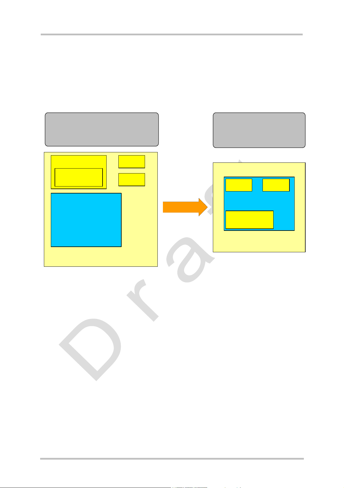
The TC65 module features an ultra-low profile and low-power consumption for data (CSD
and GPRS), voice, SMS and fax. With Java technology and several peripheral interfaces, the
module enables easy integration of your application.
This document explains how to work with the TC65 module, the installation CD and the tools
provided on the installation CD.
Old solution:
The customer application was
distributed across 2 µC, external µC
and internal µC on the module
µC
Customer SW
ROM
RAM
TCxx
Customer Application
Figure 1: Overview
New solution:
The customer application
exists only on the module
ROM
RAM
TC65
Customer SW
Customer Application
2.1 Related Documents
In addition to the Java Docs for the development API (see Chapter 4), the following
documents are included with the SMTK:
[1] Multiplexer Installation Guide
[2] Application Note 23: Installing TC65 Module on DSB75
[3] DSB75 Support Box - Evaluation Kit for Siemens Cellular Engines
[4] TC65 AT Command Set
[5] TC65 Hardware Interface Description
[6] Java doc \wtk\doc\html\index.html
TC65 JAVA User's Guide_V01 Page 9 of 69 11.03.2005
Page 10

TC65 JAVA User's Guide
Strictly confidential / Draft
2.2 Terms and Abbreviations
Abbreviation Description
API Application Program Interface
ASC Asynchronous Serial Controller
CLDC Connected Limited Device Configuration
CSD Circuit-Switched Data
DAI Digital Audio Interface
DCD Data Carrier Detect
DSR Data Set Ready
GPIO General Purpose I/O
GPRS General Packet Radio Service
GPS Global Positioning System
HTTP Hypertext Transfer Protocol
s
I/O Input/Output
IDE Integrated Development Environment
IP Internet Protocol
J2ME™ Java 2 Mobile Edition
J2SE™ Java 2 Standard Edition
JAD Java Application Description
JAR Java Archive
JDK Java Development Kit
JVM Java Virtual Machine
LED Light Emitting Diode
ME Mobile Engine
MIDP Mobile Information Device Protocol
OTA Over The Air
OTAP Over The Air Provisioning of Java Applications
PDP Packet Data Protocol
PDU Protocol Data Unit
SDK Standard Development Kit
SMS Short Message Service
SMTK Siemens Mobile Toolkit
TCP Transfer Control Protocol
URC Unsolicited Result Code
URL Universal Resource Locator
VBS Visual Basic Script
WTK Wireless Toolkit
TC65 JAVA User's Guide_V01 Page 10 of 69 11.03.2005
Page 11

TC65 JAVA User's Guide
s
Strictly confidential / Draft
3 Installation
3.1 System Requirements
The Siemens Mobility Toolkit (SMTK) TC65 requires that you have:
1. Windows 2000 or Windows XP installed
2. 40Mbytes free disk space for SMTK
3. Administration privileges
4. Java 2 SDK, Standard Edition 1.4. To install the JDK version 1.4.2_07 provided, follow
the instructions in Section 3.3.1.
If a Java IDE such as Sun Java Studio Mobility 6 2004Q3, Eclipse 3.0, JBuilder 9, X or 2005
is installed, it can be integrated into the SMTK environment during the installation of the
SMTK. To install one of the IDEs, follow the installation instructions in Section 3.3.3 and
Section 3.3.4 respectively.
3.2 Installation CD
The Siemens Mobility Toolkit TC65 Installation CD includes:
• Module Exchange Suite
• wtk
- bin
- doc
- - html
- java docs for APIs
- lib
- - classes.zip
- src
- various examples
• AT Java Open Framework
• Network applications
• ftp
• mail
• JDK 1.4.2_07
- J2sdk-1_4_2_07-windows-i586-p.exe
• Sun Java Studio Mobility 6
- ffj_me_win32.exe
• Documents:
- DSB75_HW_Description.pdf
- TC65_AT_Command_Set.pdf
- TC65_HW_Description.pdf
- WM_AN_24_dev_guide.pdf
- TC65_ReleaseNote.pdf
- TC65_Java_UserGuide.pdf (this document)
TC65 JAVA User's Guide_V01 Page 11 of 69 11.03.2005
Page 12

TC65 JAVA User's Guide
Strictly confidential / Draft
s
3.2.1 Components
3.2.1.1 Module Exchange Suite
The Module Exchange Suite allows the developer to access the Flash file system on the
cellular engine from the development environment over a serial interface. File transfers from
PC to module are greatly facilitated by this suite.
3.2.1.2 WTK
wtk is the directory where all the necessary components for TC65 Java application creation
and debugging are stored.
3.2.1.3 AT Java Open Framework (AJOF)
The AJOF allows the developer to write Java applications for the module without dealing
directly with AT Commands.
3.2.1.4 Network Applications
The provided classes for ftp and mail help system integrators and developers to design their
own network applications.
TC65 JAVA User's Guide_V01 Page 12 of 69 11.03.2005
Page 13

TC65 JAVA User's Guide
Strictly confidential / Draft
s
3.3 SMTK Installation
The SMTK comes with an installation CD. The installation program automatically installs the
necessary components and IDE integrations. Software can be uninstalled and updated with
the install program. The next sections cover the installation and removal of the SMTK and
the installation of the SDK and the supported IDEs.
3.3.1 Installing the Standard Development Toolkit
1. The JDK version 1.4.2_07 is provided on the TC65 SMTK installation disk in the
subdirectory “JDK 1.4”. To begin the installation, start the j2sdk-1_4_2_07-windows-i586p.exe and follow the instructions of the JDK setup procedure. If there is no JDK installed
on the target machine the installation of the provided JDK will be offered automatically
during the SMTK installation process.
2. Once the toolkit has been installed, the environment variable “path” can be altered to
comfortably use the JDK tools. This is not necessary for using the Siemens SMTK.
3. Open the Control Panel.
a) Open System.
b) Click on Advanced.
c) Click on the Environment Variables button.
d) Choose path from the list of system variables.
e) Append the path for the bin directory of the newly installed SDK to the list of
directories for the path variable.
3.3.2 Installing the SMTK Environment
1. Insert CD, start setup.exe. If the dialog box appears simply press the “Next” button to
continue the procedure.
2. You will be asked to read the license agreement. If you accept the agreement, press
“Next” to continue with the installation.
3. You will be asked to read the license agreement for Mail4ME Java Mail Support. If you
accept the agreement, press “Next” to continue with the installation.
4. A file including special information about the installation and use of the SMTK is shown.
Press “Next” to continue.
5. The installation software checks for the SDK. If there is no SDK on the system the
installation procedure offers the installation of the provided JDK now. If this step is denied
the setup process will not continue because a properly installed JDK is mandatory for
using the SMTK environment.
6. At this point, the installation software checks for a Java IDE to be integrated with the
SMTK. A Java IDE is not necessary to use the TC65 SMTK. The IDE installation can be
done at any time even if the TC65 SMTK is installed already. To integrate the SMTK into
the Java IDE run the SMTK setup program in maintenance mode again. However, you
can continue the setup procedure and install the IDE installation later or cancel the setup
program at this stage and restart it after installing one of the supported Java IDEs. In
case you wish to install a Java IDE please follow the instructions in Section 3.3.3 and the
following.
7. If the SDK and one or more Java IDEs are found, you will be asked to choose which IDE
you want integrated into the TC65 development environment. Once an IDE has been
found and selected, press "Next" to continue. Ensure that your Java IDE is closed.
8. Select the folder where the TC65 SMTK will be installed. A folder will be suggested to
you but you may browse to select a different one.
TC65 JAVA User's Guide_V01 Page 13 of 69 11.03.2005
Page 14

TC65 JAVA User's Guide
Strictly confidential / Draft
9. Choose the path that TC65 will appear under in the Start Menu.
10. A brief summary of all entries made shows up.
11. After step 9, all necessary files will be copied from the CD into the target folder.
12. This is the final step. Again, a listing of all installed components appears.
s
3.3.3 Installing Sun Java Studio Mobility 6
1. Sun Java Studio Mobility 6 is provided on the TC65 SMTK installation disk in the
subdirectory “SunOne ME”. To begin installation, start the ffj_me_win32.exe and follow
the instructions of the Sun Studio setup procedure.
2. On the first use of Sun™ Studio 6 after installation, you will be prompted to specify a
personal Java folder when Sun Studio is started for the first time. If more then one user
uses the computer, each user may have their own Java folder.
Note: The integration of the SMTK into Sun™ Studio 6 is only possible if the personal
user folder is set. It can only be rolled back by the user who installed the SMTK. If all
users use the same Java folder, any user may roll back the integration.
3.3.4 Installing Eclipse 3.0
Eclipse can be freely downloaded from http://www.eclipse.org.
3.3.5 Installing Borland JBuilder 9, X and 2005
Borland JBuilder can be purchased from http://www.borland.com/jbuilder.
Note: The installation path name of JBuilder should not include space characters.
There are also 30 days trial versions available there. Installation instructions can be found on
the web page.
TC65 JAVA User's Guide_V01 Page 14 of 69 11.03.2005
Page 15

TC65 JAVA User's Guide
Strictly confidential / Draft
s
3.4 SMTK Uninstall
The TC65 SMTK install package comes with an uninstall facility. The entire SMTK or parts of
the package can be removed. To start the uninstall facility, open the Control Panel, select
Add/Remove Programs, select TC65 and follow the instructions.
3.5 Upgrades
The SMTK can be modified, repaired or removed by running the setup program on the
Installation CD.
TC65 JAVA User's Guide_V01 Page 15 of 69 11.03.2005
Page 16

TC65 JAVA User's Guide
s
Strictly confidential / Draft
4 Software Platform
In this chapter, we discuss the software architecture of the SMTK and the interfaces to it.
4.1 Software Architecture
The SMTK enables a customer to develop a Java application on a PC and have it be
executable on the TC65 module. The application is loaded onto the module. The platform
comprises:
• Basis is the Java™ 2 Micro Edition (J2ME™)
The J2ME™ is provided by SUN Microsystems, http://java.sun.com/j2me/
designed for embedded systems and has a small memory footprint. TC65 uses:
. It is specifically
- CLDC 1.1 HI, the connected limited device configuration hot spot implementation.
- IMP-NG, the information module profile 2
nd
generation, this is for the most part
identical to MIDP 2.0 but without the lcdui package.
• Additional Java virtual machine interfaces:
AT Command API
File I/O API
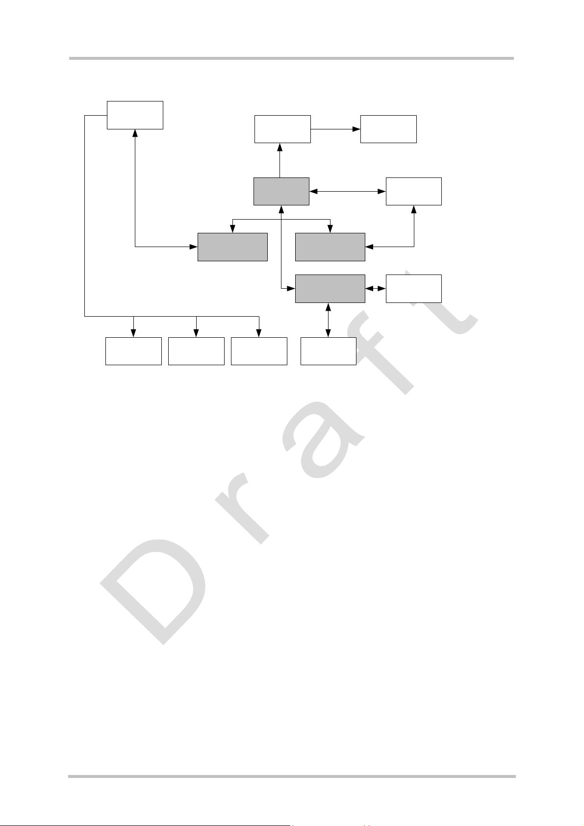
The data flow through these interfaces is shown in Figure 3 and Figure 20.
• Memory space for Java programs:
Flash File System: around 1700k
RAM: around 400k
Applications code and data share the space in the flash file system and in RAM.
• Additional accessible periphery for Java applications
- A maximum of ten shared digital I/O pins usable, for example, as:
Output: status LEDs
- Input: Emergency Button
- One I2C/SPI Interface.
- One Digital Analog Converter and two Analog Digital Converters.
-
- Serial interface (RS-232 API): This standard serial interface could be used, for
example, with an external GPS device or a current meter.
For detailed information see chapter 4.2.
TC65 JAVA User's Guide_V01 Page 16 of 69 11.03.2005
Page 17

TC65 JAVA User's Guide
Strictly confidential / Draft
s
4.2 Interfaces
4.2.1 ASC0 - Serial Device
ASC0, an Asynchronous Serial Controller, is a 9-wire serial interface. It is described in the
Hardware Interface Description [5]. Without a running Java application the module can be
controlled by sending AT commands via ASC0. Furthermore ASC0 is designed for
transferring files from the development PC to the module and for controlling the module with
AT commands. When a Java application started, ASC0 can be used as an RS-232 port, refer
to Java doc [6].
4.2.2 General Purpose I/O
There are ten I/O pins that can be configured for general purpose I/O. When TC65 starts up,
all 10 pins are set, by default, to high-impedance state for use as input. One pin can be
configured as pulse counter. See [4] and [5] about configuring the pins.
4.2.3 DAC/ADC
TBD
4.2.4 ASC1
ASC1 is the second serial interface on the module. This is a 4-pin interface (RX, TX, RTS,
CTS). It can be used as a second AT interface when a Java application is not running or by a
running Java application as System.out.
4.2.5 Digital Audio Interface (DAI)
To support the DAI function, the TC65 has a five-line serial interface with one input data
clock line and input/output data and frame lines. Refer to AT Command Set [4] and Hardware
Interface Description document [5] for more information.
4.2.6 I2C/SPI
There is a 4 line serial interface which can be used as I2C or SPI interface. It is described in
the Hardware Interface Description [5]. The at^sspi at command configures and drives this
interface. For details see [5].
TC65 JAVA User's Guide_V01 Page 17 of 69 11.03.2005
Page 18

TC65 JAVA User's Guide
Strictly confidential / Draft
s
4.2.7 JVM Interfaces
IMP-NG File API AT Command API
Connected Limited Device Configuration (CLDC)
J2ME
Figure 2: Interface Configuration
J2ME, CLDC and MIDP were implemented by SUN. IMP-NG is a stripped down version of
MIDP 2.0 prepared by Siemens and does not include the graphical interface LCDUI.
Siemens developed the File I/O API and the AT command API. Documentation for J2ME and
CLDC can be found at http://java.sun.com/j2me/
in …/ Java doc [6].
. Documentation for the other APIs is found
4.2.7.1 IP Networking
IMP-NG provides access to TCP/IP like MIDP 2.0.
Because the used network connection, CSD or GPRS, is fully transparent to the Java
interface, the CSD and GPRS parameters must be defined separately either by the AT
command at^sjnet [4] or by parameters given to the connector open method, see Java doc
[6].
4.2.7.2 Media
TC65 supports only a subset of the optional media package, see Java doc [6].
4.2.7.3 Others
TC65 does neither support the PushRegistry interfaces and mechanisms nor any URL
schemes for the PlatformRequest method. See Java doc [6].
TC65 JAVA User's Guide_V01 Page 18 of 69 11.03.2005
Page 19
TC65 JAVA User's Guide
s
Strictly confidential / Draft
4.3 Data Flow of a Java Application Running on the Module
AT Parser
system.out ASC1
Flash File
System
TCP/IP
GPIO
DAI
AT Command
API
I2C/SPI DAC/ADC
JVM
File I/O API
IMP-NG
ASC0
Figure 3: Data flow of a Java application running on the module.
The diagram shows the data flow of a Java application running on the module. The data flow
of a Java application running in the debug environment can be found in Figure 20.
The compiled Java applications are stored as JAR files in Flash File System of module.
When the application is started, the JVM interprets the JAR file and calls the interfaces to
module environment.
The module environment consists of:
• Flash File System: available memory for Java applications
• TCP/IP: module internal TCP/IP stack
• GPIO: general purpose I/O
• DAI: Digital Audio Interface
• ASC0: Asynchronous serial interface 0
• ASC1: Asynchronous serial interface 1
• I2C: I2C bus interface
• SPI: Serial Peripheral Interface
• DAC: digital analog converter
• ADC: analog digital converter
• AT parser: accessible AT parser
The Java environment on the module consists of:
• JVM: Java Virtual Machine
• AT command API: Java API to AT parser
• File API: Java API to Flash File System
• IMP-NG: Java API to TCP/IP
[D2]and ASC0
TC65 JAVA User's Guide_V01 Page 19 of 69 11.03.2005
Page 20
TC65 JAVA User's Guide
s
Strictly confidential / Draft
4.4 Handling Interfaces and Data Service Resources
To develop Java applications the developer must know which resources, data services and
hardware access are available.
• There are three AT parsers available
• There is hardware access over
- two serial interfaces: ASC1 (System.out only) and ASC0 (fully accessible).
- general purpose I/O. To configure the hardware access, please refer to the AT
Command Set [4] and the Hardware Interface Description [5].
- I2C/SPI
- All restrictions of combinations are described in section 4.4.1.
-
• A Java application has:
- three instances of the AT command class, one with CSD and two without, each of
which would, in turn, be attached to one of the three AT parsers.
- one instance of access to a serial interface, ASC0, through the RS-232 API.
- System.out over the serial interface, ASC1, for debugging.
-
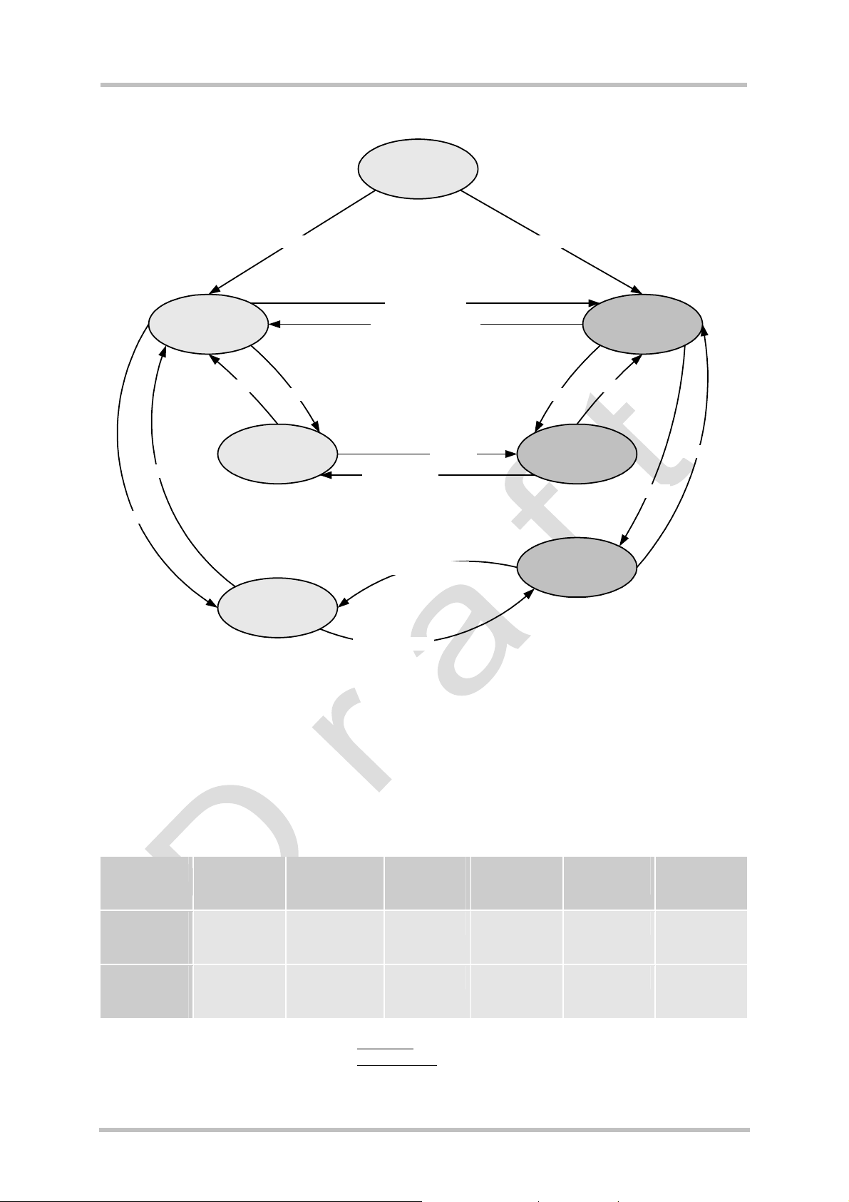
4.4.1 Module States
The module can exist in the following six states vis-à-vis a Java application and the four I/O
pins, (pin group 0), used for ASC1 and general purpose I/O. See the AT Command Set [4] for
information about any AT commands referenced. A state transition diagram is shown in Figure
10.
This section shows how Java applications must share AT parsers, GPIO pins I2C/SPI
resources. DAC, ADC and DAI are not mentioned here. The USB interface is alternative to
ASC1, meaning when USB is plugged in the ASC1 interface is deactivated.
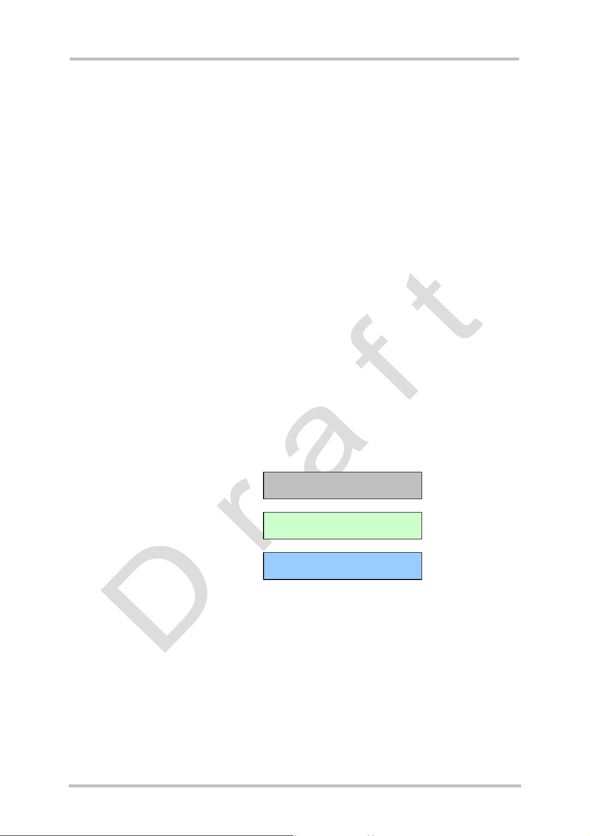
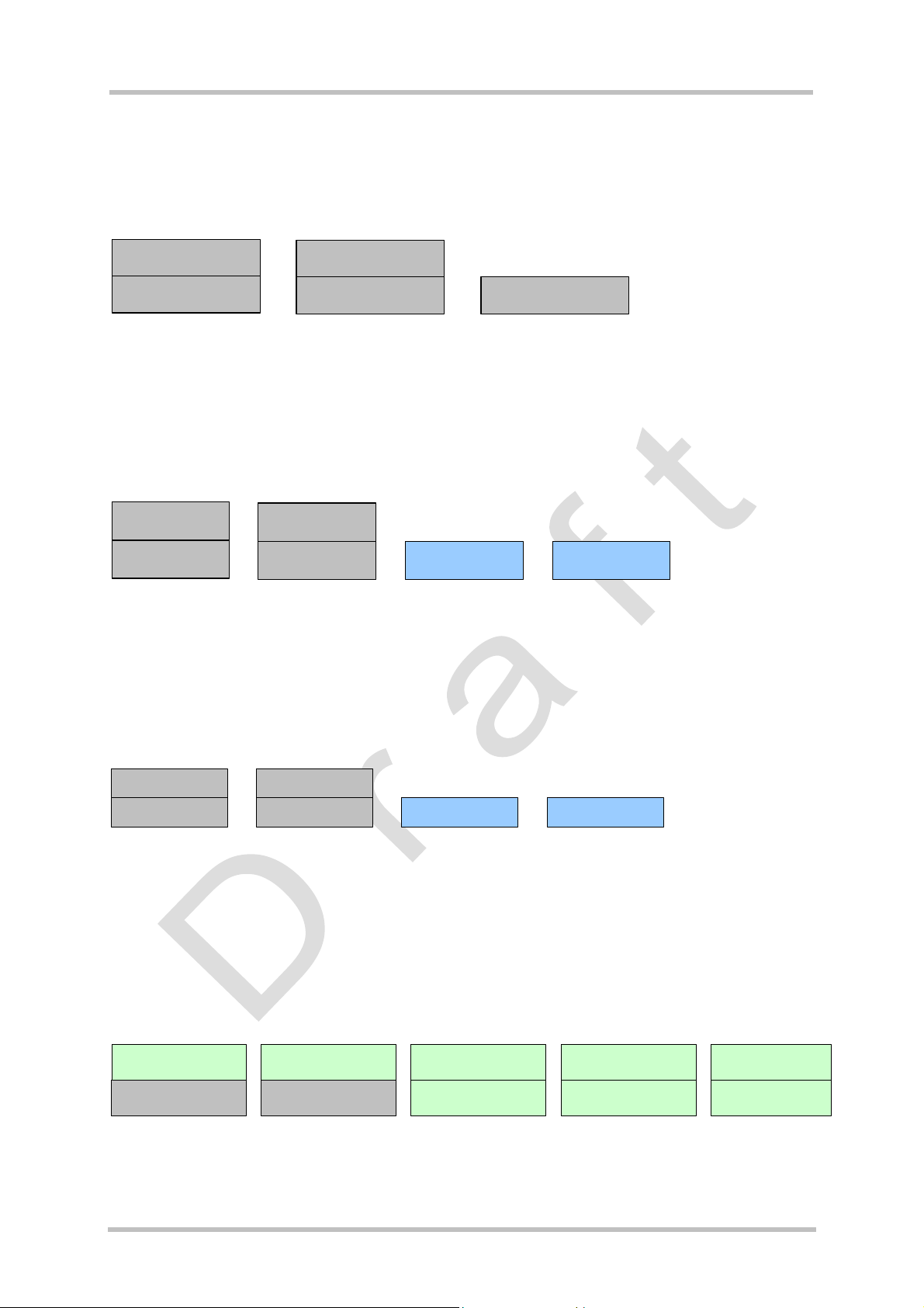
Default configuration of module
Default configuration when Java
application is started
configured by AT Command
Legend of colors in following figures
TC65 JAVA User's Guide_V01 Page 20 of 69 11.03.2005
Page 21
TC65 JAVA User's Guide
s
Strictly confidential / Draft
4.4.1.1 State 1: Default – No Java Running
This is the default state. The Java application is inactive and there is an AT interface with
CSD on ASC0 as well as ASC1. All HW interface pins are configured as inputs.
AT parser
with CSD
ASC 0
AT parser
with CSD
ASC1 or USB
10 GPIO, I2C/SPI pins
(unused)
Figure 4: Module State 1
4.4.1.2 State 2: No Java Running, General Purpose I/O and I2C
The Java application is inactive. There is an AT parser with CSD on ASC0 as well as ASC1.
Up to ten I/0 pins are used as general purpose I/O plus a I2C interface. The pins are
configured by at^scpin (refer to AT Command Set [4]).
AT parser
with CSD
AT par ser
with CSD
ASC 0
ASC 1 or USB I2C
up to 10 GPIO pins
Figure 5: Module State 2
4.4.1.3 State 3: No Java Running, General Purpose I/O and SPI
The Java application is inactive and there is an AT interface with CSD on ASC0 as well as
ASC1. Up to ten I/0 pins are used as general purpose I/O plus a SPI interface. The pins are
configured by at^scpin (refer to AT Command Set [4]).
AT parser
with CSD
ASC 0
AT parser
with CSD
up to 10 GPIOs SPIASC 1 or USB
Figure 6: Module State 3
4.4.1.4 State 4: Default – Java Application Active
The Java application is active and ASC1 is used as System.out and the Java instance of the
RS-232 serial interface is connected to ASC1. Java instances of AT command are connected
to the available AT parsers. The Java application is activated with at^sjra (refer to AT
Command Set [4]) or autostart.
Java access to serial
interface (CommConnection)
ASC 0
Syst em.out
ASC1
AT parser
with CSD
Java AT command API
with CSD
AT parser
without CSD
Java AT command API
without CSD
AT parser
wit hout CSD
Java AT command API
wit hout CSD
Figure 7: Module State 4
TC65 JAVA User's Guide_V01 Page 21 of 69 11.03.2005
Page 22
TC65 JAVA User's Guide
s
Strictly confidential / Draft
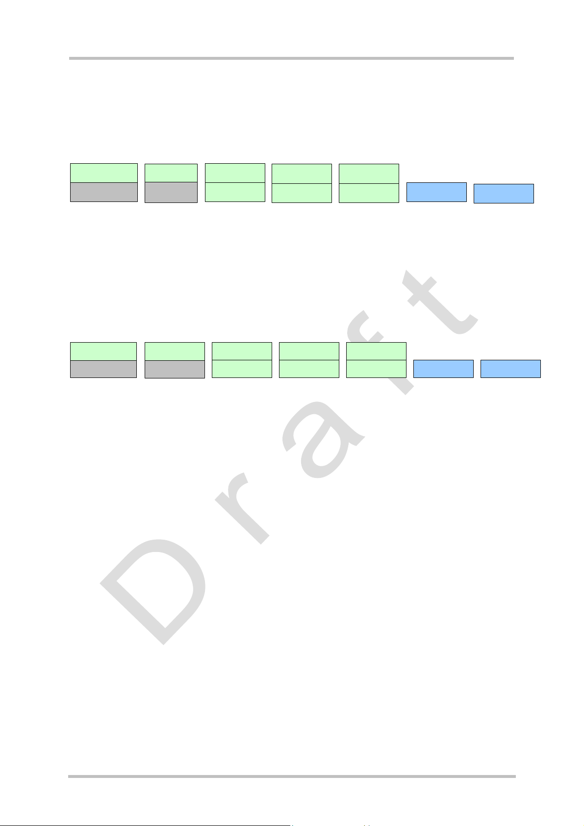
4.4.1.5 State 5: Java Application Active, General Purpose I/O and I2C
The Java application is active, ASC0 is used as System.out and the Java instance of the
RS-232 serial interface is connected to ASC1. The Java application is activated with at^sjra.
The I/O pins are configured by at^scpin. Refer to the AT Command Set [4] for AT command
details.
Java access to seri al
int erface (CommConnection)
ASC 0
System.out
ASC 1
AT parser 0
with CSD
Java AT command API
with CSD
AT par ser
without CSD
Java AT command API
without CSD
AT parser
without CSD
Java AT command API
without CSD
up to 10 GPIO pins:
I2C:
Figure 8: Module State 5
4.4.1.6 State 6: Java Application Active, General Purpose I/O and SPI
The Java application is running, ASC0 is used as System.out and the Java instance of the
RS-232 serial interface is connected to ASC1. The Java application is activated with at^sjra
(refer to AT Command Set [4]).
Java access to serial
inter face (CommConnecti on)
ASC 0
System.out
ASC 1
Figure 9: Module State 6
AT parser 0
wit h CSD
Java AT c ommand API
wit h CSD
AT parser
without CSD
Java AT co mmand API
without CSD
AT parser
without CSD
Java AT command API
without CSD
up to 10 GPIO pins SPI
TC65 JAVA User's Guide_V01 Page 22 of 69 11.03.2005
Page 23
TC65 JAVA User's Guide
Strictly confidential / Draft
4.4.2 Module State Transitions
switch on
no Java autostart Java autostart
start java: at^sjra
State 1: Default, no Java
appl. running
destroy java application
s
State 4: Default,
Java active
close SPI
open SPI
close I2C
State 2: no Java appl.
State 3: no Java appl.
open I2C
running, using I2C
running, using SPI
start java:
destroy
Java application
destroy java application
start java: at^sjra
at^sjra
open I2C
State 5: Java active,
State 6: Java active,
using I2C
using SPI
close I2C
close SPI
open SPI
Figure 10: Module State Transition Diagram
Note: No AT parser is available over serial interface ASC0 or ASC1 while a Java application
is running on the module.
• System.out is available on ASC1 for debugging while a Java application is running.
• Comparison of Java AT command APIs:
Table 1: Java AT commands
Voice calls
incoming
outgoing
Java AT
z z z
command API
with CSD
Java AT
z
command API
without CSD
z indicates that the functionality is available from the Java AT command API
--- indicates that the functionality is not available
1)
except for AT commands related to data calls
2)
only two Java AT command APIs can be used in parallel to transmit GPRS data
Data calls
incoming
outgoing
-
SMS
incoming
outgoing
z
GPRS
connection
Phonebook
management
z2)
z2)
z z
z
from the Java AT command API
AT
commands
z 1)
TC65 JAVA User's Guide_V01 Page 23 of 69 11.03.2005
Page 24

TC65 JAVA User's Guide
Strictly confidential / Draft
s
5 Maintenance
Basic maintenance features of the TC65 are described below. Explicit details of these
functions and modes can be found in the AT Command Set [4] and the Hardware Interface
Description [5].
5.1 Power Saving
The module supports several power saving modes which can be configured by the AT
command at+cfun [4]. Power saving affects the Java application in two ways. On the one
hand it limits the access to the serial interface (RS-232-API) and the GPIO pins and on the
other hand power saving efficiency is directly influenced by the way a Java application is
programmed.
Java hardware access limitations:
• In NON-CYCLIC SLEEP mode (cfun=0) the serial interface cannot be accessed while in
CYCLIC SLEEP mode (CFUN=7 or 9) the serial interface can be used with hardware flow
control (CTS/RTS).
• In all SLEEP modes the GPIO polling frequency is reduced, so that only signal changes
which are less than 0.2Hz can be detected properly. Furthermore it should be mentioned
that the signal must be constant for at least 2.12s to detect changes. For further details
refer to [5].
Java power saving efficiency:
• As long as any Java thread is active, power consumption cannot be reduced, regardless
whether any SLEEP mode has been activated or not. So a Java application that wants to
be power efficient should not have any unnecessarily active threads (e.g. no busy loops).
5.2 Charging
Please refer to [4] and [5] for general information about charging. Charging can be monitored
by the running Java application. The JVM is active in Charge mode and when autostart is
activated also in Charge-Only mode. Only a limited number of AT commands are available
when the module is in Charge-Only mode. A Java application must be able to handle the
Charge-Only mode and reset the module to reinstate the normal mode. See [5] for
information about the Charge-Only mode.
The Charge-Only mode is indicated by URC “SYSSTART CHARGE-ONLY MODE”.
Note: When a Java application is started in Charge-Only mode only AT Command APIs
without CSD are available. The indicating URC is created after issuing the very first AT
command on any opened channel. To read the URC it is necessary to register a listener (see
[6]) on this AT command API instance before passing the first AT command.
TC65 JAVA User's Guide_V01 Page 24 of 69 11.03.2005
Page 25

TC65 JAVA User's Guide
Strictly confidential / Draft
s
5.3 Airplane Mode
The main characteristic of this mode is that the RF is switched off and therefore only a limited
set of AT commands is available. The mode can be entered or left using the appropriate
at^scfg command. This AT command can also be used to configure the airplane mode as the
standard startup mode, see [5]. The JVM is started when autostart is enabled. A Java
application must be able to handle this mode. The airplane mode is indicated by URC
“SYSSTART AIRPLANE MODE”. Since the radio is off all classes related to networking
connections, e.g. SocketConnection, UDPDatagramConnection, SocketServerConnection,
HTTPConnection, will through an exception when accessed.
5.4 Alarm
The ALARM can be set by the at+cala AT command. Please refer to the AT Command Set
[4] and Hardware Interface Description [5] for more information. One can set an alarm, switch
off the module with at^smso, and have the module restart at the time set with at+cala. When
the alarm triggers the module restarts in a limited functionality mode, the “airplane mode”.
Only a limited number of AT commands is available in this mode, though the JVM is started
when autostart is enabled. A Java application must be able to handle this mode and reset the
module to reinstate the normal mode.
The airplane mode is indicated by URC “SYSSTART AIRPLANE MODE”.
Note: For detailed information which functionality is available in this mode see [5]. The mode
indicating URC is created after issuing the very first AT command on any opened channel.
TC65 JAVA User's Guide_V01 Page 25 of 69 11.03.2005
Page 26

TC65 JAVA User's Guide
Strictly confidential / Draft
s
5.5 Shut Down
In the case of an unexpected shut down, data that should be written will get lost due to a
buffered write access to the flash file system. However, the best and safest approach to
powering down the module is to issue the AT^SMSO command. This procedure lets the
engine log off from the network and allows the software to enter into a secure state and save
all data. Further details can be found in [5].
5.5.1 Automatic Shutdown
The module is switched off automatically in different situations:
• under- or overtemperature
• under- or overvoltage
This will happen without a warning notification unless the appropriate URC has been
activated. If the URCs are enabled, the module will deliver an alert before switching off. To
activate the URCs for temperature conditions use the at^sctm command, to activate the
undervoltage URC use the at^sbc command. It is recommended that these URCs be
activated so that the module can be shut by the application with at^smso after setting an
alarm, see Section 5.4. Please note that there is no URC function available for overvoltage
conditions, i.e. no alert will be sent before shutdown. The commands are described in the AT
Command Set [4], while a description of the shutdown procedure can be found in [5].
5.5.2 Restart after Switch Off
The module can be switched off with the AT command, at^smso without setting an alarm
time, see the AT Command Set [4].
module is switched off, external hardware must restart the module with the Ignition line (IGT).
The Hardware Interface Description [5] explains how to handle a switched off situation.
A power failure will also switch off the module. When the
TC65 JAVA User's Guide_V01 Page 26 of 69 11.03.2005
Page 27

TC65 JAVA User's Guide
Strictly confidential / Draft
s
5.6 Special AT Command Set for Java Applications
For the full AT command set refer to [4]. There are differences in the behaviour of issuing AT
commands from a Java application compared to using AT commands over a serial interface.
5.6.1 Switching from Data Mode to Command Mode
Cancelling the data flow with “+++” is not available in Java applications, see [4] for details. To
break the data flow use breakConnection(), refer to \wtk\doc\index.html [6].
5.6.2 Mode Indication after MIDlet Startup
As on the serial interface after starting the module without autobauding on, the module sends
its state (^SYSSTART, ^SYSSTART ALARM MODE etc.) to the MIDlet. This is done via URC
to the AT Command API instance which executes the very first AT Command from within
Java. To read this URC it is necessary to register a listener (see [6]) on this AT Command
API instance before passing the first AT Command.
5.6.3 Long Responses
The AT Command API can handle responses of AT commands up to a length of 1024 bytes.
Some AT commands have responses longer than 1024 bytes, for these responses the Java
application will receive an Exception.
Existing workarounds:
• Instead of listing the whole phone book, read the entries one by one
• Instead of listing the entire short message memory, again list message after message
• Similarly, read the provider list piecewise
• Periods of monitoring commands have to be handled by Java, i.e. at^moni, at^smong.
These AT commands have to be used without parameters, i.e. at^moni the periods have
to be implemented in Java.
5.6.4 Configuration of Serial Interface
While a Java application is running on the module, only the AT Command API is able to
handle AT commands. All AT commands referring to serial interface are ignored. Especially
these are the following:
• AT+IPR
• AT\Q3
If Java is running, the firmware will ignore any settings from these commands. Responses to
the read, write or test commands will be invalid or deliver “ERROR”.
Note:
When a Java application is running, all settings of the serial interface are done by the class
CommConnection. This is fully independent of any AT commands relating a serial interface.
5.6.5 Java Commands
There is a small set of special Java AT commands:
TC65 JAVA User's Guide_V01 Page 27 of 69 11.03.2005
Page 28

TC65 JAVA User's Guide
Strictly confidential / Draft
• at^sjra, start of Java application
• at^sjnet, the configuration for Java networking connection
• at^sjotap, start and configuration of the over the air provisioning
• at^sjsec, security configuration
Refer to AT command set [4].
s
5.7 Restrictions
5.7.1 Flash File System
The maximum length of a complete path name, including the path and the filename, is limited
by the Flash file system on the module to 124 characters.
It is recommended to distinguish names of classes and files not only by case sensitivity.
5.7.2 Memory
The CLDC 1.1 HI features a just in time compiler. That means that parts of the Java byte
code which are frequently are translated into machine code to improve efficiency. This
feature uses up RAM space. So there is always a trade off between code translation to
speed up execution and RAM space available for the application.
TC65 JAVA User's Guide_V01 Page 28 of 69 11.03.2005
Page 29
TC65 JAVA User's Guide
s
Strictly confidential / Draft
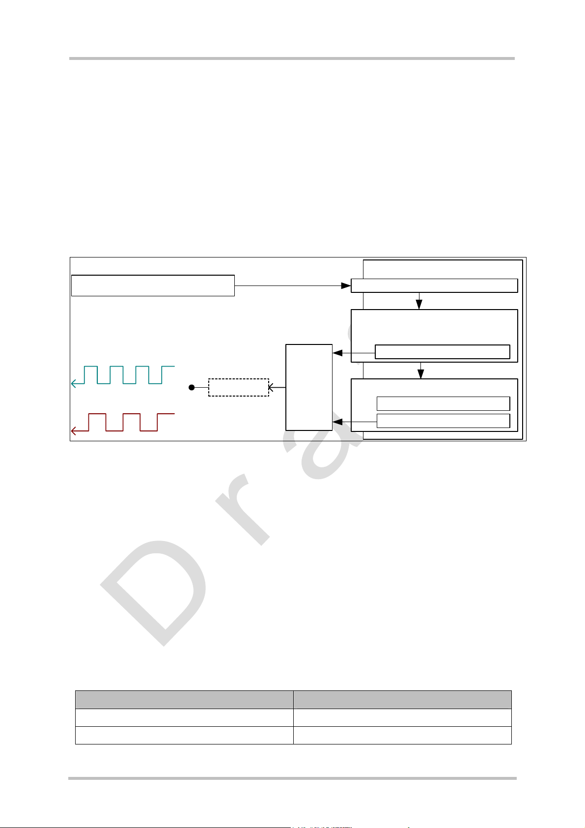
5.8 Performance Statements
Scope of the performance study was getting comparable values that indicate the
performance under certain circumstances.
5.8.1 Java
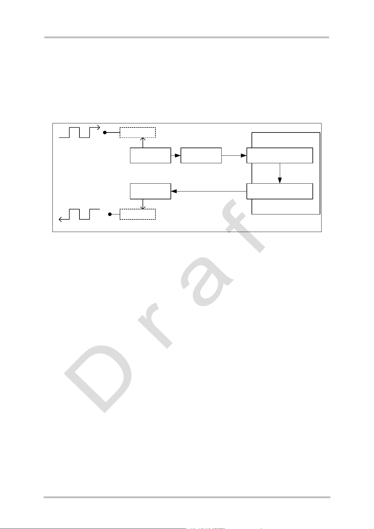
This section gives information about the Java command execution throughput (“jPS”= Java
statements per second). The scope of this measurement is only the statement execution
Î
time, not the execution delay (Java command on AT interface
Î
reaction on GPIO).
Send URC (start performance test) ATCommandListener.ATEvent()
Java instruction execution
Test MIDlet
Reference loop (for frequency A)
Generated frequency A
[reference sequence]
Generated frequency B
[measurement sequence]
Output pin
Change
output
pin level
Measurement loop (for frequency B)
ATCommand.send(...)
Measurement sequence
ATCommand.send(...)
Figure 11: Test case for measuring Java command execution throughput
The following Java instruction was used for calculation of the typical jPS:
value = ( 2 x number of calculation statements ) /
( ( 1 / frequencyB ) - ( 1 / frequencyA ) );
Measurement and calculation were done using:
• duration of each loop = 600 s
• number of calculation statements = 5 “
result=(CONSTANT_VALUE/variable_value);”-Instructions
(executed twice per pin cycle)
• frequencyA as measured with universal counter
• frequencyB as measured with universal counter
The reference loop has the same structure as the measurement loop except that the
measurement sequence is moved.
State jPS-Value (mean)
TC65 module in IDLE mode / Not connected ~750 jPS
CSD connection ~450 jPS
These mean values may be sporadically reduced depending on dynamic conditions.
TC65 JAVA User's Guide_V01 Page 29 of 69 11.03.2005
Page 30
TC65 JAVA User's Guide
s
Strictly confidential / Draft
5.8.2 Pin-IO
The pin IO test was defined to find out how fast a Java MIDlet can process URCs caused by
Pin IO and react on these URCs.
The URCs are generated by feeding an input pin with an external frequency. As soon as the
Java MIDlet gets informed about the URC, it tries to regenerate the feeding frequency by
toggling another output pin.
input pin
Test MIDlet
external frequency
poll input pin
send URC
ATCommandListener.
ATEvent()
set output pin
output pin
generated frequency
Figure 12: Test case for measuring Java MIDlet performance and handling pin-IO
ATCommand.
send(...)
The results of this test show that the delay from changing the state on the pin to processing
the URC in the MIDlet is at least 20 TDMA frames, but depends mainly on the amount of
garbage to collect and number of thread to serve by the virtual machine. So Pin IO is not
suitable to generate or detect frequencies.
5.8.3 Data Rates on RS-232 API
For details about software platform and interfaces refer to Chapter 4, "Software Platform".
This section summarises limitations and preconditions for performance when using the
interface CommConnection from package com.siemens.mp.io (refer to [6]).
The data rate on RS232 depends on the size of the buffer used for reading from and writing
to the serial interface. It is recommended to use for reading from serial interface the method
read (byte[ ] b). The recommended buffer size is 2kbyte.
To reach errorfree data transmission the flowcontrol on CommConnection has to be switched
on: <autorts> and <autocts>, the same for connected device.
Below, different use cases are listed to give an idea of reachable data rates. All applications
for measurements are working with only one thread, no more activities than those described
were done in parallel.
5.8.3.1 Plain Serial Interface
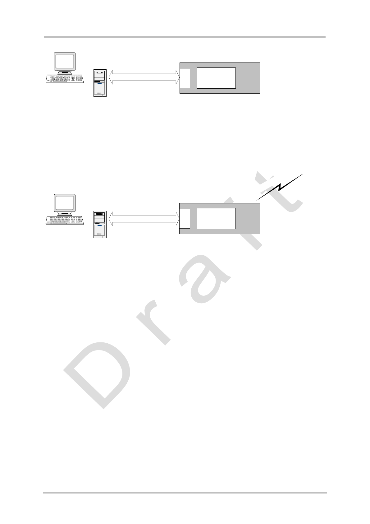
Scenario: A device is connected to ASC0 (refer to 4.2.4). The Java application has to handle
data input and output streams.
A simple Java application (only one thread) which is looping incoming data directly to output
reaches data rates up to 140kbit/s. Test conditions: hardware flow control enabled (<autorts>
and <autocts>) and baud rate on ASC0 set to 230kbit/s.
TC65 JAVA User's Guide_V01 Page 30 of 69 11.03.2005
Page 31
TC65 JAVA User's Guide
Strictly confidential / Draft
s
ASC1
Java
application
(looping data)
TC65
Figure 13: Scenario for testing data rates on ASC1
5.8.3.2 Voice Call in Parallel
Same scenario as in section 5.8.3.1, but a voice call added. The application is reflecting
incoming data directly to output and, additionally, handles an incoming voice call. The data
rates are up to 119kbit/s. Test conditions: baud rate on ASC0 set to 230kbit/s.
l
l
a
c
e
c
i
o
v
g
n
i
m
o
c
n
i
ASC1
Java
application
(looping data)
Figure 14: Scenario for testing data rates on ASC1 with a voice call in parallel
TC65
TC65 JAVA User's Guide_V01 Page 31 of 69 11.03.2005
Page 32
TC65 JAVA User's Guide
s
Strictly confidential / Draft
5.8.3.3 Scenarios with GPRS Connection
The biggest challenge for the module performance is setting up a GPRS connection,
receiving data on interfaces of javax.microedition.io and sending or receiving the data on the
RS232 API with the help of a Java application.
5.8.3.3.1 Upload
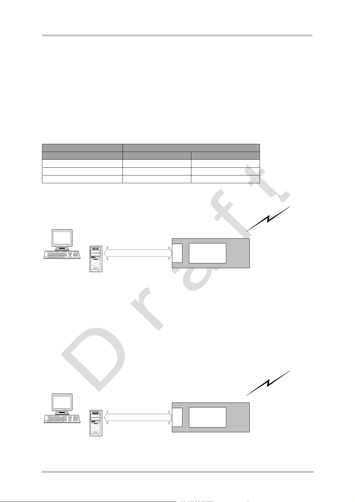
TC65 supports GPRS class 8, this means one timeslot for upload data is available. The Java
application receives data over RS232 API and sends them over GPRS to a server.
Table 2: Data rate upload
Upload data rate in [kbit/s]
Data rate 11 18
Theoretical value 12 20
% from theoretical value* 91% 90%
* net transmission rates for LLC layer
Coding scheme 2 Coding scheme 4
n
o
i
t
c
e
n
n
a
t
o
c
a
d
S
d
R
a
P
o
l
G
p
u
ASC1
Java
application
(transfer data)
TC65
Figure 15: Scenario for testing data rates on ASC1 with GPRS data upload
5.8.3.3.2 Download
The data rate for downloading data over GPRS depends on the number of assigned
timeslots and the coding schemes given by the net. TC65 supports GPRS class 8, this
means the number of assigned timeslots can be up to 4.
For measurement purposes, the Java application receives data from the server over GPRS
and sends them over RS232 to an external device.
n
o
i
t
c
e
n
a
t
n
a
o
d
c
d
S
a
R
o
l
P
n
G
w
o
d
ASC1
Java
application
(transfer data)
TC65
Figure 16: Scenario for testing data rates on ASC1 with GPRS data download
TC65 JAVA User's Guide_V01 Page 32 of 69 11.03.2005
Page 33
TC65 JAVA User's Guide
s
Strictly confidential / Draft
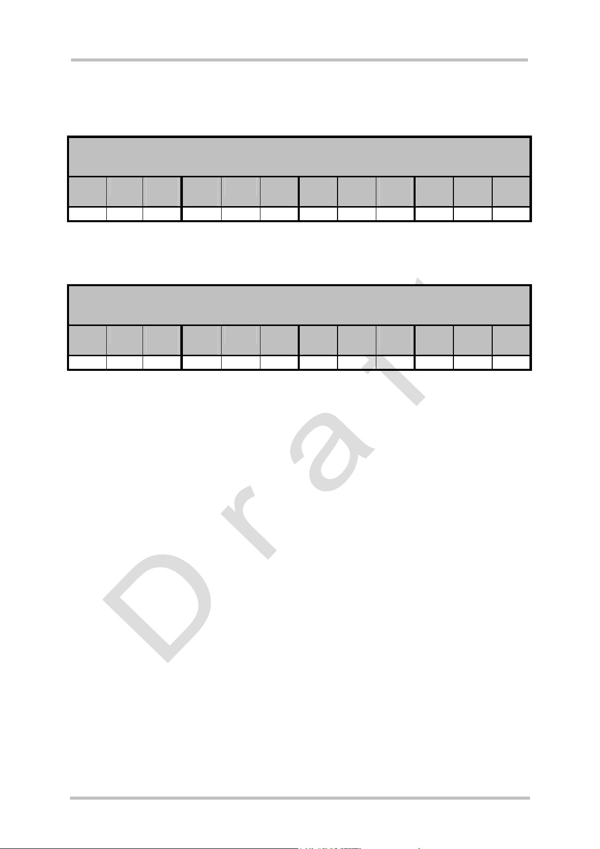
The tables below show the download data rates that can be achieved if hardware control is
enabled on the CommConnection interface.
Table 3: Download data rate with different number of timeslots, CS2
Download data rate with x timeslots
Coding scheme 2
[kbit/s]
1
timeslot
theor.
Value *
% from
theor.
Value
2
timeslots
theor.
Value *
% from
theor.
Value
3
timeslots
theor.
Value *
% from
theor.
Value
4
timeslots
theor.
Value *
% from
theor.
Value
11 12 91 % 22 24 91 % 31 36 86 % 34 48 70 %
* net transmission rates for LLC layer
Table 4: Download data rate with different number of timeslots, CS4
Download data rate with x timeslots
Coding scheme 4
[kbit/s]
1
timeslot
theor.
Value *
% from
theor.
value
2
timeslots
theor.
Value *
% from
theor.
value
3
timeslots
theor.
Value *
% from
theor.
value
4
timeslots
theor.
Value *
% from
theor.
value
18 20 90 % 31 40 77 % 34 60 56 % 38 80 47 %
* net transmission rates for LLC layer
TC65 JAVA User's Guide_V01 Page 33 of 69 11.03.2005
Page 34

TC65 JAVA User's Guide
Strictly confidential / Draft
s
6 MIDlets
The J2ME™ Mobile Information Device Profile (MIDP) provides a targeted Java API for
writing wireless applications. The MIDP runs on top of the Connected Limited Device
Configuration (CLDC), which in turn, runs on top of the J2ME™. MIDP applications are
referred to as MIDlets. MIDlets are controlled by the mobile device implementation that
supports the CLDC and MIDP. Since IMP-NG is a subset of MIDP 2.0, IMP includes MIDlets.
The MIDlet code structure is very similar to applet code. There is no main method and
MIDlets always extend from the MIDlet class. The MIDlet class in the MIDlet package
provides methods to manage a MIDlet’s life cycle.
6.1 MIDlet Documentation
MIDP and MIDlet documentation can be found at http://wireless.java.sun.com/midp/ and in
the html document directory of the wtk,
…\Siemens\SMTK\TC65wtk\doc\index.html
6.2 MIDlet Life Cycle
The MIDlet life cycle defines the protocol between a MIDlet and its environment through a
simple well-defined state machine, a concise definition of the MIDlet’s states and APIs to
signal changes between the states. A MIDlet has three valid states:
• Paused – The MIDlet is initialised and is quiescent. It should not be holding or using any
shared resources.
• Active – The MIDlet is functioning normally.
• Destroyed – The MIDlet has released all of its resources and terminated. This state is
only entered once.
State changes are affected by the MIDlet interface, which consists of:
• pauseApp() – the MIDlet should release any temporary resources and become passive.
• startApp() – the MIDlet starts it’s execution, needed resources can be acquire here or in
the MIDlet constructor
• destroyApp() – the MIDlet should save any state and release all resources
• Note: destroyApp() is called when a MIDlet should terminate caused by device.
• notifyDestroyed() – the MIDlet notifies the application management software that it has
cleaned up and is done
• Note: the only way to terminate a MIDlet is to call notifyDestroyed(), but destroyApp() is
not automatically called by notifyDestroyed().
• notifyPaused() – the MIDlet notifies the application management software that it has
paused
• resumeRequest() – the MIDlet asks application management software to be started
again.
° getAppProperty() – gets a named property from the MIDlet
TC65 JAVA User's Guide_V01 Page 34 of 69 11.03.2005
Page 35

TC65 JAVA User's Guide
Strictly confidential / Draft
Table 5: A typical sequence of MIDlet execution
Application Management Software MIDlet
s
The application management software creates a new instance of a
MIDlet.
The application management software has decided that it is an
appropriate time for the MIDlet to run, so it calls the
MIDlet.startApp method for it to enter the Active state.
The application management software no longer needs the
application be active, so it signals it to stop performing its service
by calling the MIDlet.pauseApp method.
The application management software has determined that the
MIDlet is no longer needed, or perhaps needs to make room for a
higher priority application in memory, so it signals the MIDlet that
it is a candidate to be destroyed by calling the
MIDlet.destroyApp method.
The default (no argument)
constructor for the MIDlet is
called; it is in the Paused state.
The MIDlet acquires any
resources it needs and begins to
perform its service.
The MIDlet stops performing its
service and might choose to
release some resources it
currently holds.
If it has been designed to do so,
the MIDlet saves state or user
preferences and performs clean
up.
TC65 JAVA User's Guide_V01 Page 35 of 69 11.03.2005
Page 36

TC65 JAVA User's Guide
s
Strictly confidential / Draft
6.3 Hello World MIDlet
Here is a sample HelloWorld program.
/**
* HelloWorld.java
*/
package example.helloworld;
import javax.microedition.midlet.*;
import java.io.*;
public class HelloWorld extends MIDlet {
/**
* HelloWorld - default constructor
*/
public HelloWorld() {
System.out.println("HelloWorld: Constructor");
}
/**
* startApp()
*/
public void startApp() throws MIDletStateChangeException {
System.out.println("HelloWorld: startApp");
System.out.println("\nHello World!\n");
destroyApp();
}
/**
* pauseApp()
*/
public void pauseApp() {
System.out.println("HelloWorld: pauseApp()");
}
/**
* destroyApp()
*/
public void destroyApp(boolean cond) {
System.out.println("HelloWorld: destroyApp(" + cond + ")");
notifyDestroyed();
}
}
TC65 JAVA User's Guide_V01 Page 36 of 69 11.03.2005
Page 37

TC65 JAVA User's Guide
Strictly confidential / Draft
s
7 AT Java Open Framework (AJOF)
7.1 AT Commands
The TC65 AT Command Set [4] contains all of the standard AT commands needed to operate a GSM/GPRS mobile. Please note that no fax commands are supported when the TC65
is operated in the Java environment. Simply issuing individual AT commands can control the
TC65 module. See the “AT Command Set” to learn more about AT commands. The AT Java
Open Framework allows an application to be built without dealing with individual AT
commands. This framework sits on top of the AT command API.
The AT commands have been divided into six functional areas. Each area is represented as
a package. Documentation for the methods of each area and the AT commands covered by
these methods can be found in …\Siemens\SMTK\TC65\AJOF\doc\index.html, [10]
Extensions are possible to this framework. The Java tutorial in Chapter 13 gives examples
on how to use this framework.
.
7.1.1 Mobile Engine Sstatus
This area abstracts AT commands which affect the ME status, either by setting or returning
device parameters. The methods supplied in this category are mostly query methods. Most
of the methods in this category can be called regardless of the ME’s current status. The
values set by these methods remain valid after the method call is finished.
7.1.2 Voice Call Handling
This category provides the methods for the handling of voice calls. Some of these methods
can only be executed successfully when the module is in a particular state.
7.1.3 Short Message Service
There are two formats, text and PDU, for sending short messages. The developer can create
messages of both formats, however, AJOF handles SMs internally in the PDU format. With
this framework, sending a short message should be as simple as writing a string to the
screen. The methods provided do all the appropriate conversions for reading or preparing an
SM. These conversions are transparent to the application programmer.
7.1.4 Phonebook Features
The phonebook methods provide access to the phonebook storage media. This class
provides methods to select a storage medium, list the stored entries, write into, browse
through, read or delete from a storage medium.
7.1.5 Pin I/O
The pin I/O class provides methods for configuring the pins, writing to and reading from the
pins, configuring the pins as a port and listening to the pins/port.
TC65 JAVA User's Guide_V01 Page 37 of 69 11.03.2005
Page 38

TC65 JAVA User's Guide
Strictly confidential / Draft
s
8 File Transfer to Module
8.1 Module Exchange Suite
The Module Exchange Suite allows you to view the Flash file system on the module as a
directory from Windows Explorer. Make sure that the module is turned on and that ASC0 of
the module is connected to the configured COM port of Module Exchange Suite. The
adjustment of the configured COM port can be checked by attributes on Module directory.
Please note that the Module Exchange Suite can be used only if the module is in normal
mode.
While running the module with Module Exchange Suite subdirectories and files can be added
in flash file system of module. Take in mind that only the maximum of 200 flash objects (files
and subdirectories) per directory in flash file system of module are recommended.
8.1.1 Windows Based
The directory is called “Module” and can be found at the top level of workspace
“MyComputer”. To transfer a file to the module, simply copy the file from the source directory
to the target directory in the “Module -> Module Disk (A:)”.
8.1.2 Command Line Based
A suite of command line tools is available for accessing the module’s Flash file system. They
are installed in the Windows System directory so that the tools are available from any
directory. The module’s file system is accessed with mod:. The tools included in this suite are
MESdel, MEScopy, MESxcopy, MESdir, MESmkdir, MESrmdir, MESport and MESformat.
Entering one of these commands without arguments will describe the command’s usage. The
tools mimic the standard directory and file commands. A path inside the module’s file system
is identified by using “mod:” followed by the module disk which is always “A:” (e.g. “MESdir
mod:a:” lists the contents of the module’s root directory).
8.2 Over the Air Provisioning
See Chapter 9 for OTA provisioning.
8.3 Security Issues
The developer should be aware of the following security issues. Security aspects in general
are discussed in chapter 12.
TC65 JAVA User's Guide_V01 Page 38 of 69 11.03.2005
Page 39

TC65 JAVA User's Guide
Strictly confidential / Draft
s
8.3.1 Module Exchange Suite
The serial interface should be mechanically protected.
The copy protection rules for Java applications prevent opening, reading, copying, moving or
renaming of JAR files. It is not recommended to use names of Java applications (for example
<name>.jar) for directories, since the copy protection will deny access to open, copy or
rename such directories.
8.3.2 OTAP
• A password should be used to update with OTA (SMS Authentication)
• Parameters should be set to fixed values (at^sjotap
cannot be changed over the air.
• The http server should be secure. (e.g. Access control via basic authentication)
) whenever possible so that they
TC65 JAVA User's Guide_V01 Page 39 of 69 11.03.2005
Page 40
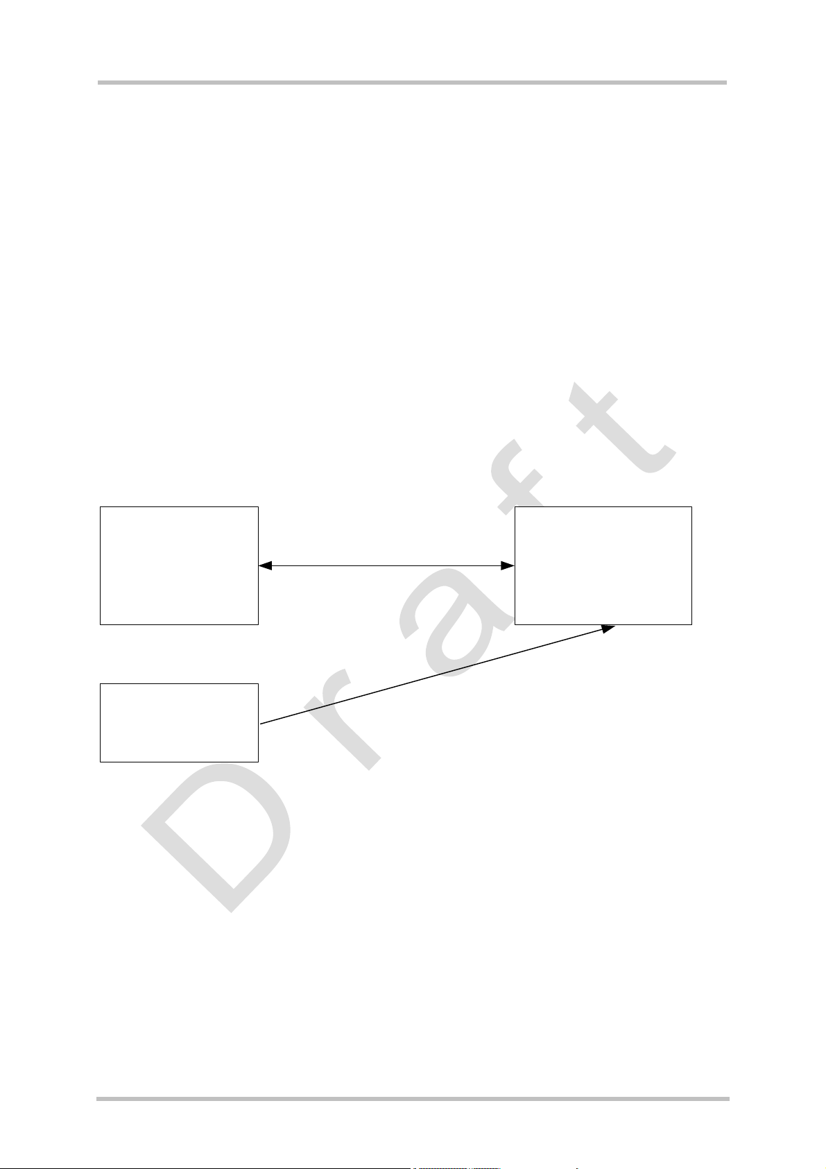
TC65 JAVA User's Guide
Strictly confidential / Draft
s
9 Over The Air Provisioning (OTAP)
9.1 Introduction to OTAP
OTA (Over The Air) Provisioning of Java Applications is a common practice in the Java
world. OTAP describes mechanisms to install, update and delete Java applications over the
air. The TC65 product implements the Over The Air Application Provisioning as specified in
the IMP-NG standard.
The OTAP mechanism described in this document does not require any physical user
interaction with the device; it can be fully controlled over the air interface. Therefore it is
suitable for Java devices that are not supposed to have any manual interaction like vending
machines or electricity meters.
9.2 OTAP Overview
To use OTAP, the developer needs, apart from the device fitted with the TC65 module, an
http server, which is reachable through a TCP/IP connection either over GPRS or CSD, and
an SMS sender, which can send Class1, PID $7d short messages. This is the PID reserved
for module’s data download.
Java Application Server
(HTTP Server)
.jar file
.jad file
OTAP Controller
(SMS Sender)
The Java Application Server (http Server) contains the .jar and the .jad file, which are to be
loaded on the device. Access to these files can be protected by http basic authentication.
The OTAP Controller (SMS Sender) controls the OTAP operations. It sends SMs, with or
without additional parameters, to the devices that are to be operated. These devices then try
to contact the http server and download new application data from it. The OTAP Controller
will not get any response about the result of the operation. Optionally the server might get a
result response through http.
There are two types of OTAP operations:
• Install/Update: A new JAR and JAD file are downloaded and installed.
• Delete: A complete application (.jar, .jad, all application data and its directory) is deleted.
HTTP/TCP/IP
over GPRS/CSD
d
Pi
,
1
s
s
a
l
C
S
M
S
Figure 17: OTAP Overview
$
Device containing TC65
.jad file
.jar file
d
7
TC65 JAVA User's Guide_V01 Page 40 of 69 11.03.2005
Page 41

TC65 JAVA User's Guide
s
Strictly confidential / Draft
9.3 OTAP Parameters
There is a set of parameters that control the OTAP procedures. These parameters can either
be set by AT command (at^sjotap
production of the device, or by SM (see Section 9.4) during operation of the device in the
field. None of the parameters, which are set by AT command, can be overwritten by SM.
• JAD File URL: the location of the JAD file is used for install or update procedures. The
JAD file needs to be located on the net (e.g. http://someserver.net/somefile.jad
http://192.168.1.2/somefile.jad
• Application Directory: this is the directory where a new application (JAD and JAR file) is
installed. The delete operation deletes this directory completely. When entering the
application directory by at^sjotap
terminated with a slash. For example, type "a:" or "a:/otap" rather than "a:/" or "a:/otap/".
See examples provided in Chapter 9.4.
• http User: a username used for authentication with the http server.
• http Password: a password used for authentication with the http server.
• Bearer:
the network bearer used to open the HTTP/TCP/IP connection, either GPRS or
CSD.
• APN or Number: depending on the selected network bearer this is either an access point
name for GPRS or a telephone number for CSD.
• Net User: a username used for authentication with the network.
• Net Password: a password used for authentication with the network.
• DNS: a Domain Name Server’s IP address used to query hostnames.
• NotifyURL: the URL to which results are posted
There is one additional parameter that can only be set by AT command:
• SM Password: it is used to authenticate incoming OTAP SMs. Setting this password gives
an extra level of security.
Note: If there was a password set by AT command, all SMs have to include this password
, refer to AT Command Set [7]) presumably during the
or
).
or short message be sure that the path name is not
Table 6: Parameters and keywords
Parameters Max. Length AT Keyword SM Install/update delete
JAD File URL 100 JADURL mandatory unused
Application Directory 50 APPDIR mandatory mandatory
HTTP User 32 HTTPUSER optional unused
HTTP Password 32 HTTPPWD optional unused
Bearer -- BEARER mandatory unused
APN or Number 65 APNORNUM mandatory for CSD unused
Net User 32 NETUSER optional unused
Net Password 32 NETPWD optional unused
DNS -- DNS optional unused
Notify URL 100 NOTIFYURL optional unused
SM Password 32 PWD optional optional
The length of the string parameters in the AT command is limited (see Table 6), the length in
the SM is only limited by the maximum SM length.
The minimum set of required parameters depends on the intended operation (see Table 6).
TC65 JAVA User's Guide_V01 Page 41 of 69 11.03.2005
Page 42

TC65 JAVA User's Guide
Strictly confidential / Draft
s
9.4 Short Message Format
An OTAP control SM must be a Submit PDU with Class1, PID $7d and 8 bit encoding. As a
fallback for unusual network infrastructures the SM can also be of Class0 and/or PID $00.
The content of the SM consists of a set of keywords and parameter values. These
parameters might be distributed over several SMs. There is one single keyword to start the
OTAP procedure. For parameters that are repeated in several SMs only the last value sent is
valid. For example, an SM could look like this:
Install operation:
First SM: OTAP_IMPNG
PWD:secret
JADURL:http://www.greatcompany.com/coolapps/mega.jad
APPDIR:a:/work/appdir
HTTPUSER:user
HTTPPWD:anothersecret
Second SM: OTAP_IMPNG
PWD:secret
BEARER:gprs
APNORNUM:access.to-thenet.net
NETUSER:nobody
NETPWD:nothing
DNS:192.168.1.2
START:install
Delete operation:
OTAP_IMP1.0
PWD:secret
APPDIR:a:/work/appdir
START:delete
The
first line is required: it is used to identify an OTAP SM. All other lines are optional and
their order is insignificant, each line is terminated with an LF: '\n' even the last one. The
keywords, in capital letters, are case sensitive. A colon separates the keywords from their
values.
The values of APPDIR, BEARER and START are used internally and have to be lower case.
The password (PWD) is case sensitive. The case sensitivity of the other parameter values
depends on the server application or the network. It
sent in one SM. They can be distributed over several SMs. Of course, every SM needs to
contain the identifying first line and the PWD parameter, if necessary. The OTAP is started
when the keyword START, possibly with a parameter, is contained in the SM and the
parameter set is valid for the requested operation. It always ends with a reboot, either when
the operation is completed, an error occurred, or the safety timer expired. This also means all
parameters previously set by SM are gone.
Apart from the first and the last line in this example, these are the parameters described in
the previous section. Possible parameters for the START keyword are: “install”, “delete” or
nothing. In the last case, an install operation is done by default.
The network does not guarantee the order of SMs. So when using multiple SMs to start a
is likely that not all parameters can be
TC65 JAVA User's Guide_V01 Page 42 of 69 11.03.2005
Page 43

TC65 JAVA User's Guide
Strictly confidential / Draft
OTAP operation their order on the receiving side might be different from the order in which
they were sent. This could lead to trouble because the OTAP operation probably starts
before all parameters are received. If you discover such problems, try to wait a few seconds
between sending the SMs.
s
9.5 Java File Format
In general, all Java files have to comply with the IMP 1.0 and TC65 specifications. There are
certain components of the JAD file that the developer must pay attention to when using
OTAP:
• MIDlet-Jar-URL: make sure that this parameter points to a location on the network where
• MIDlet-Install-Notify: this is an optional entry specifying a URL to which the result of an
• MIDlet-Name, MIDlet-Version, MIDlet-Vendor: are mandatory entries in the JAD and
• MIDlet-Jar-Size must contain the correct size of the jar file, otherwise result 904 (see 9.7)
Example:
MIDlet-Name: MyTest
MIDlet-Version: 1.0.1
MIDlet-Vendor: TLR Inc.
MIDlet-Jar-URL: http://192.168.1.3/datafiles/MyTest.jar
MIDlet-Description: My very important test
MIDlet-1: MyTest, , example.mytest.MyTest
MIDlet-Jar-Size: 1442
MicroEdition-Profile: IMP-NG
MicroEdition-Configuration: CLDC-1.1
A suitable Manifest file for the JAD file above might look like:
Manifest-Version: 1.0
MIDlet-Name: MyTest
MIDlet-Version: 1.0.1
MIDlet-Vendor: TLR Inc.
MIDlet-1: MyTest, , example.mytest.MyTest
MicroEdition-Profile: IMP-NG
MicroEdition-Configuration: CLDC-1.1
your latest JAR files will be located, e.g. http://192.168.1.3/datafiles/mytest.jar, not in the
filesystem like file://a:/java/mytest/mytest.jar. Otherwise this JAD file is useless for OTAP.
update/install operation is posted. That is the only way to get any feedback about the
outcome of an install/update operation. The format of the posted URL complies with the
MIDP OTA Provisioning specification. In contrast to the jar and jad file this URL must not
be protected by basic authentication.
Manifest file. Both files must contain equal values, otherwise result 905 (see 9.7) is
returned.
is returned.
TC65 JAVA User's Guide_V01 Page 43 of 69 11.03.2005
Page 44

TC65 JAVA User's Guide
Strictly confidential / Draft
9.6 Procedures
9.6.1 Install/Update
s
OTAP
Controller
Java Application
Server
Parameter SMS
Parameter SMS with "START:install"
HTTP request for .jad file
(HTTP basic authentication)
HTTP .jad file download
HTTP request for .jar file
(HTTP basic authentication)
HTTP download of .jar file
...
(HTTP Post Error)
(HTTP Post Result)
TC65
-SMS password check
-Parameters collection
- Combination of SMS parameter
set and AT parameter set
- If parameter set complete:
Close running Java application
Closedown
Timeout
Start install/update procedure
Download .jad file
If Error, post and
reboot
Download .jar file
-Post result,
-If success, install
and change autostart
-Reboot
Safety Timeout
Reboot
Figure 18: OTAP: Install/Update Information Flow
(The messages in brackets are optional)
When an SM with keyword START:install is received and there is a valid parameter set for
the operation, the module always reboots either when the operation completed, an error
occurred or the safety timer expired. If there is any error during an update operation the old
application is kept untouched, with one exception. If there is not enough space in the file
system to keep the old and the new application at the same time, the old application is
deleted before the download of the new one, therefore it is lost when an error occurs.
If install/update was successful the autostart is set to the new application.
TC65 JAVA User's Guide_V01 Page 44 of 69 11.03.2005
Page 45

TC65 JAVA User's Guide
Strictly confidential / Draft
9.6.2 Delete
s
OTAP
Controller
Java Application
Server
Parameter SMS
...
Parameter SMS with "START:delete"
TC65
-SMS password check
-Parameters collection
- Combination of SMS parameter
set and AT parameter set
- If parameter set complete:
Close running Java application
Closedown
Timeout
Start delete procedure
-Delete application dir
-reboot
Safety Timeout
Reboot
Figure 19: OTAP: Delete Information Flow
When an SM with keyword START:delete is received and there is a valid parameter set for
this operation, the module reboots either when the operation completed, an error occurred or
the safety timer expired. If there is any error the application is kept untouched. Autostart is
not changed. No result code is passed back.
TC65 JAVA User's Guide_V01 Page 45 of 69 11.03.2005
Page 46

TC65 JAVA User's Guide
Strictly confidential / Draft
s
9.7 Time Out Values and Result Codes
Timeouts:
• Closedown Timeout: 10 seconds
• Safety Timeout: 5 minutes
Result Codes: Supported status codes in body of the http POST request:
• 900 Success
• 901 Insufficient memory in filesystem
• 902 -not supported-
• 903 -not supported-
• 904 JAR size mismatch, given size in JAD file does not match real size of jar file
• 905 Attribute mismatch, one of the mandatory attributes MIDlet-name, MIDlet-version,
MIDlet-Vendor in the JAD file does not match those given in the JAR manifest
• 906 invalid descriptor
• 907 invalid JAR
• 908 incompatible configuration or profile
• 909 application authentication failure,
• 910 application authorization failure, tried to replace signed with unsigned version
• 911 -not supported-
• 912 -not supported-
All HTTP packets (GET, POST) send by the module contain the phone number or IMEI (if
number not present) of the SIM in the User-Agent field, e.g.
User-Agent: TC65/+4917266666 Profile/IMP-NG Configuration/CLDC-1.1
This is for easy device identification at the HTTP server.
9.8 Tips and Tricks for OTAP
• For security reasons it is recommended to use an SMS password. Otherwise the “delete”
operation can remove whole directories without any authentication.
• For extra security, set up a private CSD/PPP Server and set its phone number as a fixed
parameter. This way, applications can only be downloaded from one special server.
• As a side effect, OTAP can be used to simply reboot the module. Just start an OTAP
procedure with a parameter set which does not really do anything, like a delete operation
on a nonexistent directory.
• If you don’t want to start OTAP by SMS let your Java application do it by issuing the
at^sjotap
but without the SMS part.
Note: If a malfunctioning Java application is loaded the SM method will still be needed for
another update.
• The OTAP procedure cannot be tested in the debug environment
• Be aware that the module needs to be booked into the network to do OTAP. That means
that either the Java application has to enter the PIN, the PIN needs to be disabled or
Autopin (see AT Command Set [4]) has to be used.
• The OTAP procedure might fail due to call collision, e.g. a incoming call when OTAP tries
to start a CSD connection.
command. That triggers a install/update operation as described in chapter 9.6.1
TC65 JAVA User's Guide_V01 Page 46 of 69 11.03.2005
Page 47

TC65 JAVA User's Guide
Strictly confidential / Draft
s
9.9 OTAP Tracer
For easy debugging of the OTAP scenario the OTAP procedure can be traced over the serial
interface.
TBD
TC65 JAVA User's Guide_V01 Page 47 of 69 11.03.2005
Page 48

TC65 JAVA User's Guide
Strictly confidential / Draft
s
9.10 How to
This chapter is supposed to be a step-by-step guideline for using OTAP.
1. Do you need OTAP? Is there any chance that it might be necessary to update the Java
application, install a new one or delete it? The reason might be that your device is in the
field and you cannot or do not want to do it over the serial line. If the answer is “yes” then
read through the following steps, if the answer is “no” then just consider setting the OTAP
SMS password to protect your system. Then you are done with OTAP.
2. Take a look at the parameters (chapter 9.3), which control OTAP. You have to decide
which of them you want to allow to be changed over the air (by SMS) and which you do
not. This is mainly a question of security and what you can fit into a short message. Then
set the “unchangeable” parameters with the AT command (at^sjotap).
3. Prepare the http server. The server must be reachable by your device over TCP/IP. That
means there is a route from your device over the air interface to the http server and back.
When in doubt, write a small Java application using the httpConnection Interface to test
it.
4. Prepare the JAR and JAD files which are to be loaded over the air. Make sure that these
files conform to the requirements named in chapter 9.5 and that they represent a valid
application which can be started by at^sjra.
5. Put the files (JAR and JAD) on the http Server. The files can either be publicly available
or protected through basic authentication. When in doubt try to download the files from
the server by using a common web browser on a PC, which can reach your http server
through TCP/IP.
6. Prepare the SMS sender. The sender must be able to send SMs, which conform to
chapter 9.4, to your device. When in doubt try to send “normal” SMs to your device which
can than be read out through the AT command interface.
7. Test with a local device. Send a suitable short message to your device, which completes
the necessary parameter, set and starts the operation. The operation is finished when the
device reboots. You can now check the content of the file system, if the correct jar and
jad file was loaded into the correct location.
8. Analyze error. If the above test failed, looking at your devices behavior and your http
servers access log can give you some hints on what went wrong:
- If the device did not terminate the running Java application and did not reboot, not
even after the safety timeout, either your SM was not understood (probably wrong
format) or did not properly authenticate (probably wrong password) or your
parameter set is incomplete for the requested operation.
- If the device terminated the running Java application, but did not access your http
server, and rebooted after the safety timeout, there were most likely some
problems when opening the network connection. Check your network parameters.
- If the device downloaded the jad and probably even the jar file but then rebooted
without saving them in the file system, most likely one of the errors named in
chapter 9.5 occurred. These are also the only error conditions, which can also be
reported back. They are posted to the http server if the jad file contains the
required URL.
9. Start update of remote devices. If you were able to successfully update your local device,
which is hopefully a mirror of all your remote devices, you can start the update of all other
devices.
TC65 JAVA User's Guide_V01 Page 48 of 69 11.03.2005
Page 49

TC65 JAVA User's Guide
s
Strictly confidential / Draft
10 Compiling and Running a Program without Java IDE
This chapter explains how to compile and run a Java application without a Java IDE.
10.1 Build Results
A JAR file has to be created by compiling an SMTK project. A JAR file will contain the class
files and auxiliary resources associated with an application. A JAD file contains information
(file name, size, version, etc.) on the actual content of the associated JAR file. It must be
written by the user. The JAR file has the “.jar” extension and the JAD file has the “.jad”
extension. A JAD file is always required no matter whether the module is provisioned with the
Module Exchange Suite, as described in Section 8.1, or with OTA provisioning. OTA
provisioning is described in Chapter 9.
In addition to class and resource files, a JAR file contains a manifest file, which describes the
contents of the JAR. The manifest has the name manifest.mf and is automatically stored in
the JAR file itself. An IMP manifest file for:
package example.mytest;
public class MyTest extends MIDlet
includes at least:
Manifest-Version: 1.0
MIDlet-Name: MyTest
MIDlet-Version: 1.0.1
MIDlet-Vendor: Siemens
MIDlet-1: MyTest, example.mytest.MyTest
MicroEdition-Profile: IMP-NG
MicroEdition-Configuration: CLDC-1.1
A JAD file must be written by the developer and must include at least:
MIDlet-Name: MyTest
MIDlet-Version: 1.0.1
MIDlet-Vendor: Siemens
MIDlet-1: MyTest, example.mytest.MyTest
MIDlet-Jar-URL: http://192.168.1.3/datafiles/MyTest.jar
MIDlet-Jar-Size: 1408
MicroEdition-Profile: IMP-NG
MicroEdition-Configuration: CLDC-1.1
A detailed description of these attributes and others can be found in the Java/MIDlet
documentation http://java.sun.com/j2me/docs/alt-html/WTK104_UG/Ap_Attributes.html
TC65 JAVA User's Guide_V01 Page 49 of 69 11.03.2005
Page 50

TC65 JAVA User's Guide
Strictly confidential / Draft
s
10.2 Compile
• Launch a Command Prompt. This can be done from the Programs menu or by typing
“cmd” at the Run… prompt in the Start menu.
• Change to the directory where the code to be compiled is kept.
• Compile the program with the SDK. Examples of build batch files can be found in each
sample program found in the examples directory,
…\Siemens\SMTK\TC65\wtk\src\example.
• If the compile was successful the program can be run from the command line. Examples
of run batch files can be found in the examples directories listed above as well.
The batch files for compiling and running the samples refer to master batch files in the
…\Siemens\SMTK\TC65\wtk\bin directory and are using the system environment variables
IMPNG_JDK_DIR that points to the root directory of the installed JDK and IMPNG_DIR
which points to the root directory of the Siemens-SMTK-TC65-IMPNG installation. The
installation process sets these environment variables. A modification is usually not
necessary. They might be modified (e.g. for switching to a different JDK) via the advanced
system properties as requested.
10.3 Run on the Module with Manual Start
• The application can be compiled at the prompt as discussed in Section 10.2 or in an IDE.
• Transfer the .jar and .jad file from the development platform to the desired directory on the
module using the Module Exchange Suite or OTA provisioning. Chapter 8 explains how to
download your application to the module.
• Start a terminal program and connect to ASC0.
• The command at^sjra is used to start the application and is sent to the module via your
terminal program. Either the application can be started by .jar or by .jad file.
Example:
In your terminal program enter: at^sjra=a:/java/jam/example/helloworld/helloworld.jar
If you prefer to start with .jad file: at^sjra=a:/java/jam/example/helloworld/helloworld.jad
The Flash file system on the module is referenced by “a:”.
10.4 Run on the Module with Autostart
• The application can be compiled at the prompt as discussed in Section 10.2 or in an
SMTK integrated IDE.
• Transfer the .jar and .jad file from the development platform to the desired directory on the
module using the Module Exchange Suite or OTA provisioning. See Chapter 8.
TC65 JAVA User's Guide_V01 Page 50 of 69 11.03.2005
Page 51

TC65 JAVA User's Guide
Strictly confidential / Draft
s
10.4.1 Switch on Autostart
• There is an AT command, at^scfg, to configure the autostart functionality. Please refer to
the AT Command Set [4].
• Restart the module.
10.4.2 Switch off Autostart
To switch off autostart functionality there are two possibilities:
• AT command at^scfg
• tool “autostart_off.exe” (included in the Installation CD software)
To disable the automatic start of a user application in a module these steps have to be done:
1. Connect the module to the PC
2. Make sure, that the module is switched off
3. Start the Autostart_Off program
4. Select the COM-Port
5. Press the “Autostart Off” button
TC65 JAVA User's Guide_V01 Page 51 of 69 11.03.2005
Page 52
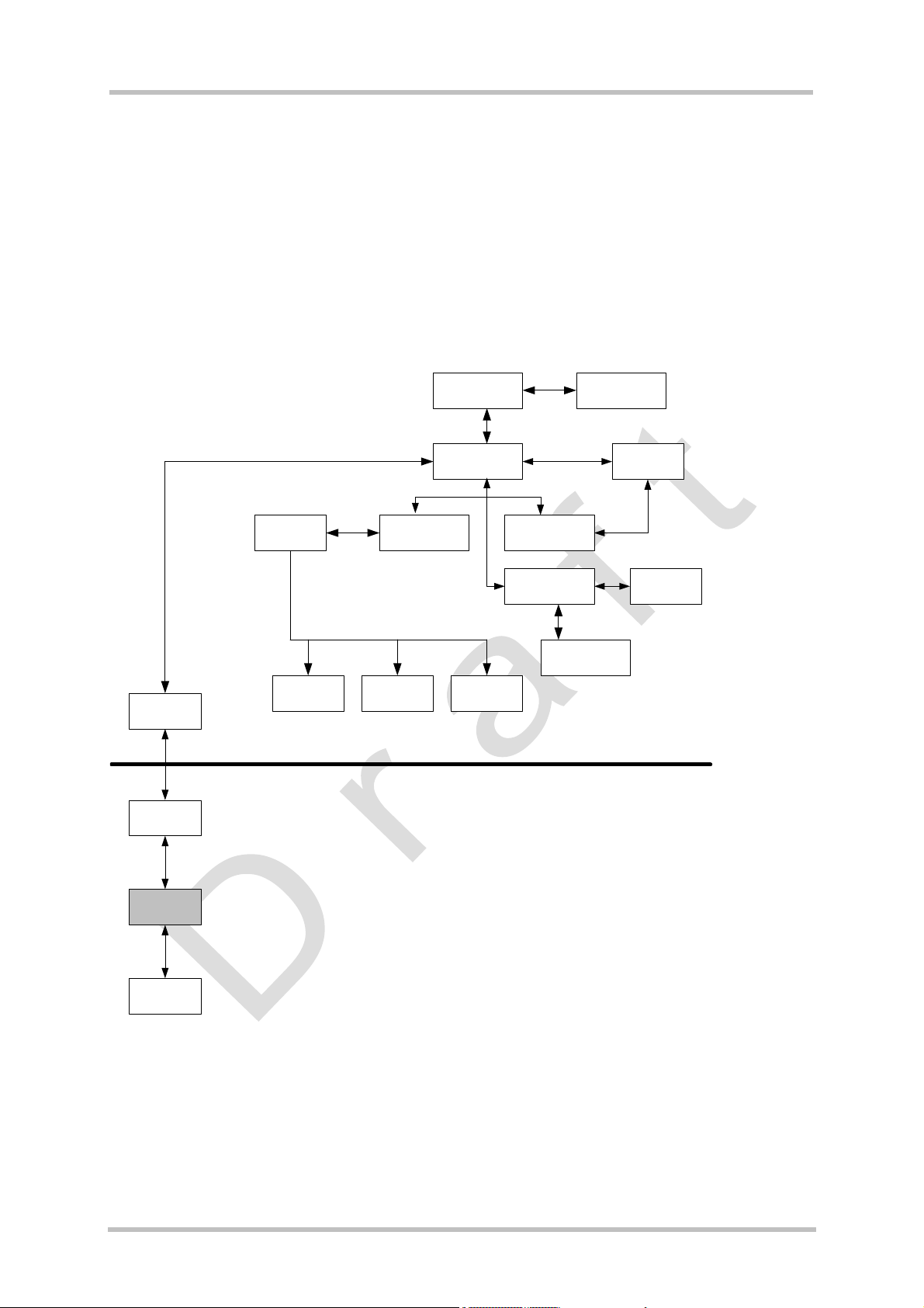
TC65 JAVA User's Guide
s
Strictly confidential / Draft
11 Debug Eenvironment
Please note that this section is not intended as a tutorial in debugging or how to use Sun
Java Studio, Borland JBuilder or Eclipse. Documents for these IDEs can be found on their respective homepages. Once the proper emulator has been selected (as described in the relevant IDE sections below), your Java application can be built, debugged and executed.
11.1 Data Flow of a Java Application in the Debug Environment
system.out ASC1
ASC0,1 or
USB
Com Port
TC65
emulator
AT parser
GPIO
DAI
AT co mma nd API
I2C/SPI
JVM
DAC/ADC
File I/O API
IMP NG
Module
PC
ASC0
Flash File
System
TCP/IP
IDE/Debug
environment
Figure 20: Data flow of a Java application in the debug environment
In the debug environment the module is connected to a PC via a serial interface. This can be
USB or a RS232 line. The application can then be edited, build and debugged within an IDE
on the PC. When running the MIDlet under debugger control it is executed on the module not
on the PC. This ensures that all interfaces behave the same no matter if in debugging mode
or not.
TC65 JAVA User's Guide_V01 Page 52 of 69 11.03.2005
Page 53

TC65 JAVA User's Guide
Strictly confidential / Draft
s
11.2 Emulator
TBD
11.3 Java IDE
The SMTK is integrated into your Java IDE during installation. Please note that the IDE
integration is intended for debugging purposes using the PC emulator. JAR files used in the
module must be configured according to the batch file examples given. If the SMTK install
succeeded, one should be able to easily switch between the Siemens environment and
Standard-JDK environment. This means that the special libraries/APIs are available, the
emulators are available, AT commands can be sent to module. Regular function of the IDE
for non-Siemens projects is unchanged.
11.3.1 Sun Java Studio Mobility 6 2004Q3
TBD
11.3.2 Borland JBuilder
TBD
11.3.3 Eclipse 3.0
TBD
11.4 Breakpoints
Breakpoints can be set as usual within the IDE. The debugger cannot step through methods
or functions whose source code is not available.
TC65 JAVA User's Guide_V01 Page 53 of 69 11.03.2005
Page 54

TC65 JAVA User's Guide
Strictly confidential / Draft
12 Java Security
TBD
12.1 Secure Data Transfer
TBD
12.2 Execution Control
TBD
12.3 Application and Data Protection
TBD
s
TC65 JAVA User's Guide_V01 Page 54 of 69 11.03.2005
Page 55

TC65 JAVA User's Guide
Strictly confidential / Draft
s
13 Java Tutorial
This small tutorial includes explanations on how to use the AT Command API, suggestions
for programming MIDlets and an example of using AJOF. The developer should read about
MIDlets, Threads and AT commands as a complement to this tutorial.
13.1 Using the AT Command API
Perhaps the most important API for the developer is the AT command API. This is the API
that lets the developer issue commands to control the module. This API consists of the
ATCommand class and the ATCommandListener and ATCommandResponseListener
interfaces. Their javadocs can be found in …\wtk\doc\html\index.html, [6].
13.1.1 Class ATCommand
The ATCommand class supports the execution of AT commands in much the same way as
they would be executed over a serial interface. It provides a simple way to send strings
directly to the device’s AT parsers.
13.1.1.1 Instantiation with or without CSD Support
There can be only exactly as many ATCommand instances as there are parsers on the
device. If there are no more parsers available, the ATCommand constructor will throw
ATCommandFailedException. All AT parser instances support CSD. However from a Java
application point of view it may make sense to have one dedicated instance for CSD call
handling. Therefore, and also for historical reasons, only one parser with CSD support may
be requested through the constructor. If more then one parser with CSD support is
requested, the constructor will throw ATCommandFailedException.
try {
ATCommand atc = new ATCommand(false);
/* An instance of ATCommand is created. CSD is not explicitly
* requested. */
} catch (ATCommandFailedException e) {
System.out.println(e);
}
The csdSupported() method returns the CSD capability of the connected instance of the
device's AT parser.
boolean csd_support = atc.csdSupported();
release() releases the resources held by the instance of the ATCommand class. After calling
this function the class instance cannot be used any more but the resources are free to be
used by a new instance
TC65 JAVA User's Guide_V01 Page 55 of 69 11.03.2005
Page 56

TC65 JAVA User's Guide
s
Strictly confidential / Draft
13.1.1.2 Sending an AT Command to the Device, the send() Method
An AT command is sent to the device by using the send() method. The AT command is sent
as a string which must include the finalizing line feed "\r" or the corresponding line end
character.
String response = atc.send(“at+cpin?\r”);
/* method returns when the module returns a response */
System.out.println(response);
Possible response printed to System.out:
+CPIN: READY OK
This send function is a blocking call, which means that the calling thread will be interrupted
until the module returns a response. The function returns the response, the result code of the
AT command, as a string.
Occasionally it may be infeasible to wait for an AT command that requires some time to be
processed, such as at+cops?
second parameter in addition to the AT command. This second parameter is a callback
instance, ATCommandResponseListener. Any response to the AT command is delivered
to the callback instance when it becomes available. The method itself returns immediately.
The ATCommandResponseListener and the non-blocking send method are described in
Section 13.1.2.
Note: Using the send methods with strings with incorrect AT command syntax will cause
mistakes.
. There is a second, non-blocking, send function which takes a
13.1.1.3 Data Connections
If a data connection is created with the ATCommand class, for instance with ‘atd’, an input
stream is opened to receive the data from the connection. Similarly, an output stream can be
opened to send data on the connection.
/* Please note that this example would not work unless the module had
* been initialized and logged into a network. */
System.out.println("Dialing: ATD" + CALLED_NO);
response = atc.send("ATD" + CALLED_NO + "\r");
System.out.println("received: " + response);
if (response.indexOf("CONNECT") >= 0) {
try {
// We have a data connection, now we do some streaming...
// IOException will be thrown if any of the Stream methods fail
OutputStream dataOut = ATCmd.getDataOutputStream();
InputStream dataIn = ATCmd.getDataInputStream();
// out streaming...
dataOut.write(new String("\n\rHello world\n\r").getBytes());
dataOut.write(new String("\n\rThis data was sent by a Java " +
"MIDlet!\n\r").getBytes());
dataOut.write(new String("Press 'Q' to close the " +
"connection\n\r").getBytes());
// ...and in streaming
System.out.println("Waiting for incoming data, currently " +
dataIn.available() + " bytes in buffer.");
rcv = 0;
TC65 JAVA User's Guide_V01 Page 56 of 69 11.03.2005
Page 57

TC65 JAVA User's Guide
s
Strictly confidential / Draft
while(((char)rcv != 'q') && ((char)rcv != 'Q') && (rcv != -1)){
rcv = dataIn.read();
if (rcv >= 0) {
System.out.print((char)rcv);
}
}
/* The example continues after the next block of text */
In …/Siemens/SMTK/TC65/wtk/src/example a complete data connection example,
DataConnectionDemo.java, can be found.
These streams behave slightly differently than regular data streams. The streams are not
closed by using the close() method. A stream remains open until the release() method is
called. A module can be switched from the data mode to the AT command mode by calling
the breakConnection() method.
/* continue example */
if (rcv != -1) {
// Now break the data connection
System.out.println("\n\n\rBreaking connection");
try {
strRcv = ATCmd.breakConnection();
} catch(Exception e) {
System.out.println(e);
}
System.out.println("received: " + strRcv);
} else {
// Received EOF, somebody else broke the connection
System.out.println("\n\n\rSomebody else switched to " +
"command mode!");
}
System.out.println("Hanging up");
strRcv = ATCmd.send("ATH\r");
System.out.println("received: " + strRcv);
} catch(IOException e) {
System.out.println(e);
}
} else {
System.out.println("No data connection established,");
}
An IOException is thrown if any function of the I/O streams are called when the module is in
AT command mode.
Data Connections are not only used for data transfer over the air but also to access external
hardware. Here is a list of at commands which open a data connection:
• atd, for data calls
• at^sspi, for access to I2C/SPI
• TBD
13.1.1.4 Synchronization
For performance reasons there is no synchronization done in this class. If an instance of this
class has to be accessed from different threads it has to be ensured that the send()
functions, the release() function, the cancelCommand() function and the
breakConnection() function are synchronized in the user implementation.
TC65 JAVA User's Guide_V01 Page 57 of 69 11.03.2005
Page 58

TC65 JAVA User's Guide
s
Strictly confidential / Draft
13.1.2 ATCommandResponseListener Interface
The ATCommandResponseListener interface defines the capabilities for receiving the
response to an AT command sent to one of the module's AT parsers. When the user wants
to use the non blocking version of the ATCommand.send function an implementation class
for the ATCommandResponseListener interface must be created first. The single method
of this class, ATResponse(), must contain the processing code for the possible response to
the sent AT command.
class MyListener implements ATCommandResponseListener {
String listen_for;
void myListener(String awaited_response) {
listen_for = awaited_response;
}
void ATResponse(String Response) {
if (Response.indexOf(listen_for) >= 0) {
System.out.println("received: " + strRcv);
}
}
}
13.1.2.1 Non-blocking ATCommand.send() Method
After creating an instance of the ATCommandResponseListener class, the class instance
can be passed as the second parameter of the non-blocking ATCommand.send() method.
After the AT command has been passed to the AT parser, the function returns immediately
and the response to the AT command is passed to this callback class later when it becomes
available
Somewhere in the application:
MyListener connect_list = new MyListener("CONNECT");
atc.send("ATD" + CALLED_NO + "\r", connect_list);
/* Application continues while the AT command is processed*/
/* When the module delivers its response to the AT command the callback
* method ATResponse is called. If the response is "CONNECT", we will see
* the printed message from ATResponse in MyListener. */
A running AT command sent with the non-blocking send function can be cancelled with
ATCommand.cancelCommand(). Any possible responses to the cancellation are sent to
the waiting callback instance.
Note: Using the send methods with strings with incorrect AT command syntax will cause
mistakes.
13.1.3 ATCommandListener Interface
The ATCommandListener interface implements callback functions for URCs, and changes
of the serial interface signals RING, DCD and DSR. The user must create an implementation
class for ATCommandListener to receive AT events. The ATEvent method of this class
must contain the processing code for the different AT-Events (URCs) and the
RINGChanged, DCDChanged and DSRChanged methods possible processing code for the
signal state changes.
TC65 JAVA User's Guide_V01 Page 58 of 69 11.03.2005
Page 59

TC65 JAVA User's Guide
s
Strictly confidential / Draft
13.1.3.1 ATEvents
An ATEvent or a URC is a report message sent from the module to the application. An
unsolicited result code can either be delivered automatically when an event occurs or as a
result of a query the module received before. However, a URC is not issued as a direct
response to an executed AT command. Some URCs must be activated with an AT
command.
Typical URCs may be information about incoming calls, received SM, changing temperature,
status of the battery etc. A summary of URCs is listed in the AT Command Set document [4].
13.1.3.2 Implementation
class ATListenerA implements ATCommandListener {
public void ATEvent(String Event) {
if (Event.indexOf("+CALA: Reminder 1") >= 0) {
/* take desired action after receiving the reminder */
} else if (Event.indexOf("+CALA: Reminder 2") >= 0) {
/* take desired action after receiving the reminder */
} else if (Event.indexOf("+CALA: Reminder 3") >= 0) {
/* take desired action after receiving the reminder */
}
/* No action taken for these events */
public void RINGChanged(boolean SignalState) {}
public void DCDChanged(boolean SignalState) {}
public void DSRChanged(boolean SignalState) {}
}
class ATListenerB implements ATCommandListener {
public void ATEvent(String Event) {
if (Event.indexOf("+SCKS: 0") >= 0) {
System.out.println("SIM Card is not inserted.");
/* perform other actions */
} else if (Event.indexOf("+SCKS: 1") >= 0) {
System.out.println("SIM Card is inserted.");
/* perform other actions */
}
}
public void RINGChanged(boolean SignalState) {
/* take some action when the RING signal changes if you want to */
}
public void DCDChanged(boolean SignalState) {
/* take some action when the DCD signal changes if you want to */
}
public void DSRChanged(boolean SignalState {}
/* take some action when the DSR signal changes if you want to */
}
}
TC65 JAVA User's Guide_V01 Page 59 of 69 11.03.2005
Page 60

TC65 JAVA User's Guide
Strictly confidential / Draft
s
13.1.3.3 Registering a Listener with an ATCommand Instance
After creating an instance of the ATCommandListener class, this class instance has to be
passed as a parameter to the ATCommand.addListener() method. After that, the callback
methods will be called by the runtime system each time the corresponding events (URCs or
signal state changes) occur on the corresponding device AT parser.
/* we have two ATCommands instances, atc1 and atc2 */
ATListenerA reminder_listener = new ATListenerA();
ATListenerB card_listener = new ATListenerB();
atc1.addListener(reminder_listener);
atc2.addListener(card_listener);
The ATCommand.removeListener() method removes a listener object that has been
previously added to the internal list table of listener objects. After it has been removed from
the list it will not be called when URCs occur. If it was not previously registered the list
remains unchanged.
The same ATCommandListener may be added to several ATCommand instances and
several ATCommandListeners may be added to the same ATCommand.
TC65 JAVA User's Guide_V01 Page 60 of 69 11.03.2005
Page 61

TC65 JAVA User's Guide
s
Strictly confidential / Draft
13.2 Programming the MIDlet
The life cycle and structure of MIDlets are described in Chapter 6. Since the MIDlets will run
on J2ME™, all of J2ME™’s features, including threads, are available. Small applications,
such as those without any timer functions or those used only for tests and simple examples,
can be written without using threads. Longer applications should be implemented with
threads.
13.2.1 Threads
Although small applications can be written without using threads longer applications should
use them. The Java programming language is naturally multi-threaded which can make a
substantial difference in the performance of your application. Therefore we recommend
referring to Java descriptions on threads before making any choices about threading models.
Threads can be created in two ways. A class can be a subclass of Thread or it can
implement Runnable.
For example, threads can be launched in startApp() and destroyed in destroyApp(). Note
that destroying Java threads can be tricky. It is recommended that the developer read the
Java documentation on threads. It may be necessary to poll a variable within the thread to
see if it is still alive.
13.2.2 Example
/* This example derives a class from Thread and creates two instances
* of the subclass. One thread instance finishes itself, the other one
* is stopped by the main application. */
package example.threaddemo;
import javax.microedition.midlet.*;
public class ThreadDemo extends MIDlet {
/* Member variables */
boolean runThreads = true; // Flag for stopping threads
DemoThread thread1; // First instance of DemoThread
DemoThread thread2; // Second instance of DemoThread
/* Private class implementing the thread to be started by the
* main application */
private class DemoThread extends Thread {
int loops;
public DemoThread(int waitTime) {
/* Store number of loops to execute */
loops = waitTime;
System.out.println("Thread(" + loops + "): Created");
}
public void run() {
System.out.println("Thread(" + loops + "): Started");
for (int i = 1; i <= loops; i++) {
/* Check if main application asked thread to die */
if (runThreads != true) {
System.out.println("Thread(" + loops + "): Stopped from outside");
/* Leave thread */
return;
}
/* Print loop counter and wait 1 second,
* do something useful here instead */
System.out.println("Thread(" + loops + "): Loop " + i);
TC65 JAVA User's Guide_V01 Page 61 of 69 11.03.2005
Page 62

TC65 JAVA User's Guide
s
Strictly confidential / Draft
try {
Thread.sleep(1000);
} catch(InterruptedException e) {
System.out.println(e);
}
}
System.out.println("Thread(" + loops + "): Finished naturally");
}
}
/**
* ThreadDemo - constructor
*/
public ThreadDemo() {
System.out.println("ThreadDemo: Constructor, creating threads");
thread1 = new DemoThread(2);
thread2 = new DemoThread(6);
}
/**
* startApp()
*/
public void startApp() throws MIDletStateChangeException {
System.out.println("ThreadDemo: startApp, starting threads");
thread1.start();
thread2.start();
System.out.println("ThreadDemo: Waiting 4 seconds before stopping threads");
try {
Thread.sleep(4000);
} catch(InterruptedException e) {
System.out.println(e);
}
destroyApp(true);
System.out.println("ThreadDemo: Closing application");
notifyDestroyed();
}
/**
* pauseApp()
*/
public void pauseApp() {
System.out.println("ThreadDemo: pauseApp()");
}
/**
* destroyApp()
*/
public void destroyApp(boolean cond) {
System.out.println("ThreadDemo: destroyApp(" + cond + ")");
System.out.println("ThreadDemo: Stopping threads from outsdide");
runThreads = false;
try {
System.out.println("ThreadDemo: Waiting for threads to die");
thread1.join();
thread2.join();
} catch(InterruptedException e) {
System.out.println(e);
}
System.out.println("ThreadDemo: All threads died");
}
}
TC65 JAVA User's Guide_V01 Page 62 of 69 11.03.2005
Page 63

TC65 JAVA User's Guide
s
Strictly confidential / Draft
13.3 AJOF
The following example uses AJOF. It demonstrates how the writing of an application for the
module is abstracted and simplified with the framework. This example does not use threads
but could be implemented in a structure similar to the one shown above.
Some comments:
• CWmMIDlet is the MIDlet instance wrapping the application. CWmMIDlet adds AT
command channel management to the standard MIDlet class.
• An AT channel, ATChannel, consists of an ATC parser and one or more listeners waiting
for URCs. The channel is distributed by the application to any class that needs access to
the module via the ATC interface.
13.3.1 Example
/* WmTutorial.java
* Copyright (C) Siemens AG 2003. All Rights reserved.
* Transmittal, reproduction and/or dissemination of this document
* as well as utilization of its contents and communication thereof
* to others without express authorization are prohibited.
* Offenders will be held liable for payment of damages.
* All rights created by patent grant or registration of a utility
* model or design patent are reserved.
*/
package example.ajoftutorial;
import com.siemens.icm.io.ATCommandFailedException;
import com.siemens.icm.ajof.WmMIDlet;
import com.siemens.icm.ajof.AtChannel;
import com.siemens.icm.ajof.AtChannel.SendTimeoutException;
import com.siemens.icm.ajof.AjofException;
import com.siemens.icm.ajof.status.WmLock;
import com.siemens.icm.ajof.status.WmLockException;
import com.siemens.icm.ajof.phonebook.SimplePhonebook;
import com.siemens.icm.ajof.phonebook.PhonebookStoreException;
import com.siemens.icm.ajof.sms.SimpleSms;
import com.siemens.icm.ajof.sms.SmsSendException;
/**
* demonstrates how easy it is to retrieve a number from the phonebook and
send an SMS message to this destination.
* @author SIEMENS AG
* @version 1
* @since AJOF 1.0
*/
public class WmTutorial extends WmMIDlet
{
// Please, change these constants to your desired settings
final String RECIPIENT_NAME = "foo, bar";
final String SERVICE_CENTRE_ADDR = "+491720000000";
final String SIM_PIN = "0000";
final String MESSAGE_TXT = "Hello, world.";
/**
* creates and sends an SMS message to a recipient, whose phone number
is retreived from the SIM phonebook.
* <ol><li>get an AT channel to communicate with the module's AT
interface
* <li>just check, if the module answers to AT commands,
TC65 JAVA User's Guide_V01 Page 63 of 69 11.03.2005
Page 64

TC65 JAVA User's Guide
s
Strictly confidential / Draft
* <li>enter the <code>SIM PIN</code>, so we can access the phonebook
and send an SMS message,
* <li>create a phonebook control and look up the recipient's phone
number,
* <li>create an SMS control,
* <li>set the service centre address (SCA),
* <li>last, but not least send the SMS message.
* <li>Please do not forget to cleanup all used resources. Each AJOF
class has a method <code>release()</code>,
* which performs this task.
* <li>Terminate the application by calling
<code>notifyDestroyed()</code>.</ol>
* @see <code>AT</code>
* @see <code>AT+CPIN</code>
* @see <code>AT+CPBR</code>
* @see <code>AT+CPMGF</code>
* @see <code>AT+CPMGS</code>
*/
public void startApp()
{
try
{
// To access the module we need an AT-channel:
AtChannel atch = openAtChannel();
// Test the connection
// (this code is optional and used only for demonstration
purposes)
System.out.println("\nTesting connection...");
String response = atch.send("at\r");
System.out.println("AT" + response);
// Set elaborated error messages
atch.send("AT+CMEE=2\r");
// Enter the SIM PIN
System.out.println("Entering PIN...");
WmLock lockControl = new WmLock(atch);
try
{
lockControl.sendSimPin(SIM_PIN);
// We create a SimplePhonebook instance
// to look into the module's phonebook.
SimplePhonebook pbk= new SimplePhonebook(atch);
try
{
// Now let's look for the SMS's recipient.
// The number is stored in the phonebook.
System.out.println("Looking up phone number for " +
RECIPIENT_NAME + ", please wait...");
String destinationAddr = pbk.getNumber(RECIPIENT_NAME);
// create a simple SMS control
SimpleSms sms = new SimpleSms(atch);
try
{
// You need to set the SCA only once in your
application
sms.setServiceCentreAddr(SERVICE_CENTRE_ADDR);
// now send the message
TC65 JAVA User's Guide_V01 Page 64 of 69 11.03.2005
Page 65

TC65 JAVA User's Guide
s
Strictly confidential / Draft
System.out.println("Sending Short Message, please
wait...");
sms.send(destinationAddr, MESSAGE_TXT);
System.out.println("Short Message was sent.");
}
catch (SmsSendException e)
{
System.out.println(e);
}
finally
{
// release the used resources
sms.release();
sms = null;
}
}
finally
{
// release the used resources
pbk.release();
pbk = null;
}
}
catch (WmLockException e)
{
System.out.println(e);
}
catch (PhonebookStoreException e)
{
System.out.println(e);
}
finally
{
// release the used resources
lockControl.release();
lockControl = null;
}
}
catch (ATCommandFailedException e)
{
System.out.println(e);
}
catch (SendTimeoutException e)
{
System.out.println("AT_Command timeout");
}
finally
{
// Terminate the application.
// You don't need to care about closing open AT channels.
// WmMIDlet does this for you.
System.out.println("Now terminating application.");
destroyApp(true);
}
}
/**
TC65 JAVA User's Guide_V01 Page 65 of 69 11.03.2005
Page 66

TC65 JAVA User's Guide
s
Strictly confidential / Draft
* Your application does not necessarily need to override
<code>destroyApp()</code>, but if it does, make sure that
* <code>super.destroyApp()</code> is called, to release the AT
channels.
*/
public void destroyApp(boolean unconditional)
{
// your finalization code goes here...
super.destroyApp(unconditional);
notifyDestroyed();
}
}
TC65 JAVA User's Guide_V01 Page 66 of 69 11.03.2005
Page 67

TC65 JAVA User's Guide
Strictly confidential / Draft
s
14 Network Applications
14.1 FTP Client
The package com.siemens.icm.ftp provides an FTP client and offers a simple interface for
transferring files between a module and a server using the File Transfer Protocol (FTP, RFC
959). The client implements a subset of RFC 959, is able to communicate with FTP servers
behind firewalls and supports binary and ASCII mode of transfer.
14.1.1 Example: FtpDemo
The MIDlet example.ftp.FtpDemo is an example for using the FTP client and exercises the
main functionality of the FTP client. FtpDemo connects to an FTP server, creates a remote
directory, transfers a file to the server and back, compares the copy against the original and
removes the remote file and directory.
Please note that the FTP client can only access files stored in the storage folder dedicated to
Java file I/O. Path names of local files are relative to the storage folder. See
com.siemens.icm.io.File
Before running the MIDlet please configure ftp.jad
properties should be set:
for more information.
to reflect your environment. The following
Property Name Description Example
example.ftp.remote.dir Remote directory incoming
example.ftp.remote.file Remote file test123
example.ftp.server FTP server ftp.siemens.de
example.ftp.user FTP user name ftp
example.ftp.pass FTP password guest
example.ftp.gprs.nameserver Name server 193.254.160.1
example.ftp.gprs.apn GRPS Access Point unused
example.ftp.gprs.user GPRS user name unused
example.ftp.gprs.pass GPRS password unused
example.ftp.modem.pin PIN for SIM card 0000
14.2 Mail Client
The package de.trantor.de is part of the Mail4Me package and provides a simple interface for
sending and receiving emails through the Simple Mail Transfer Protocol (SMTP) and the
Post Office Protocol (POP3). The mail client implements a subset of RFC 821, RFC 1939
and supports plain SMTP authentication (RFC 2554), enabling communication with SMTP
servers hardened against spam.
See mail4me.enhydra.org
for more information.
14.2.1 Example: MailDemo
The MIDlet example.mail.MailDemo is an example for using the mail client. MailDemo
creates an email, sends it through SMTP, receives it through POP3, compares the checksum
for sent and received email and displays the received email.
TC65 JAVA User's Guide_V01 Page 67 of 69 11.03.2005
Page 68

TC65 JAVA User's Guide
Strictly confidential / Draft
Before running the MIDlet please configure mail.jad to reflect your environment. The
following properties should be set:
Property Description Example
example.mail.from Sender from@mail_provider.com
example.mail.to Recipient to@mail_provider.com
example.mail.hostname Hostname of module localhost
example.mail.smtp.server SMTP server smtp.mail_provider.com
example.mail.smtp.auth Perform SMTP authentication true/false
example.mail.smtp.user SMTP user mail
example.mail.smtp.pass SMTP password ****
example.mail.pop3.server POP3 server pop3.mail_provider.com
example.mail.pop3.user POP3 user name mail
example.mail.pop3.pass POP3 password ****
example.mail.gprs.nameserver GPRS name server 193.254.160.1
example.mail.gprs.apn GPRS access point unused
example.mail.grps.user GPRS user name unused
example.mail.grps.pass GPRS password unused
example.mail.modem.pin PIN for SIM card 0000
s
TC65 JAVA User's Guide_V01 Page 68 of 69 11.03.2005
Page 69

TC65 JAVA User's Guide
Strictly confidential / Draft
s
15 Changes to TC45
For those who are familiar with the Siemens WM TC45 product this is an overview of the
main changes between TC45 and TC65.
• “real” TCP and UDP access interfaces: SocketConnection, ServerSocketConnection,
UDPDatagramConnection.
Usage of StreamConnection, StreamConnectionNotifier, DatagramConnection is now
discouraged.
• Serial interfaces swapped: Standard.out is on ASC1, CommConnection on ASC0
(->open COM0 instead of COM1)
• No IO pin multiplexing: GPIOs, DAI and the serial interface for CommConnection do not
share any pins, so the selection mechanism no longer exists.
• The CommConnection interface which used to be proprietary (
part of the standard package (
• No more interface emulation on the PC: When running a MIDlet under the emulator, it is
completely executed in the connected module and therefore uses the modules “real”
interfaces. An emulation of interfaces such as networking, file system or serial interface
on the PC side does no longer exist.
• .jad files required: A suitable descriptor file is now not only required for OTAP but in any
case. An absent or invalid .jad file is an error when starting an application (at^sjra or
autostart).
• Mandatory attributes: the attributes MicroEdition-Profile and MicroEdition-Configuration
are now mandatory attributes in the manifest and .jad file.
• Flexible echo: When using the ATCommand class the “echo” is now switchable like in no-
Java mode. Default is echo on, in TC45 the echo was always off.
javax.microedition.io).
com.siemens.icm.io) is now
TC65 JAVA User's Guide_V01 Page 69 of 69 11.03.2005
 Loading...