

Page 1
s
TC63
Siemens Cellular Engine
Version: 00.490
DocId: TC63_ATC_V00.490
AT Command Set
Page 2

TC63 AT Command Set
s
Document Name:
Version:
Date:
DocId:
Status
General Notes
Product is deemed accepted by Recipient and is provided without interface to Recipient´s products. The Product
constitutes pre-release version and code and may be changed substantially before commercial release. The
Product is provided on an “as is” basis only and may contain deficiencies or inadequacies. The Product is provided without warranty of any kind, express or implied. To the maximum extent permitted by applicable law, Siemens further disclaims all warranties, including without limitation any implied warranties of merchantability,
fitness for a particular purpose and noninfringement of third-party rights. The entire risk arising out of the use or
performance of the Product and documentation remains with Recipient. This Product is not intended for use in
life support appliances, devices or systems where a malfunction of the product can reasonably be expected to
result in personal injury. Applications incorporating the described product must be designed to be in accordance
with the technical specifications provided in these guidelines. Failure to comply with any of the required procedures can result in malfunctions or serious discrepancies in results. Furthermore, all safety instructions regarding
the use of mobile technical systems, including GSM products, which also apply to cellular phones must be followed. Siemens AG customers using or selling this product for use in any applications do so at their own risk and
agree to fully indemnify Siemens for any damages resulting from illegal use or resale. To the maximum extent
permitted by applicable law, in no event shall Siemens or its suppliers be liable for any consequential, incidental,
direct, indirect, punitive or other damages whatsoever (including, without limitation, damages for loss of business
profits, business interruption, loss of business information or data, or other pecuniary loss) arising out the use of
or inability to use the Product, even if Siemens has been advised of the possibility of such damages. Subject to
change without notice at any time.
TC63 AT Command Set
00.490
May 24, 2005
TC63_ATC_V00.490
Confidential / Draft - Do not copy
Copyright
Transmittal, reproduction, dissemination and/or editing of this document as well as utilization of its contents and
communication thereof to others without express authorization are prohibited. Offenders will be held liable for
payment of damages. All rights created by patent grant or registration of a utility model or design patent are reserved.
Copyright © Siemens AG 2005
Trademark notice
Bluetooth™ is a registered trademark of Bluetooth SIG Inc.
TC63_ATC_V00.490 Page 2 of 501 5/24/05
Confidential / Draft - Do not copy
Page 3

TC63 AT Command Set
Contents
s
Contents
1. Introduction............................................................................................................................................ 14
1.1 Scope of the document ................................................................................................................. 14
1.2 Related documents ....................................................................................................................... 15
1.3 Document conventions.................................................................................................................. 16
1.3.1 Quick reference table ....................................................................................................... 16
1.3.2 Superscript notation for parameters and values............................................................... 17
1.4 AT Command Syntax .................................................................................................................... 18
1.4.1 Using Parameters............................................................................................................. 18
1.4.2 Combining AT commands on the same command line.................................................... 19
1.5 Supported character sets .............................................................................................................. 20
1.5.1 GSM alphabet tables and UCS2 character values........................................................... 22
1.5.2 UCS2 and GSM data coding and conversion for SMS text mode.................................... 24
1.5.2.1 Implementing output of SIM data to Terminal (direction TA to TE) ................................... 24
1.5.2.2 Implementing input of Terminal data to SIM (direction TE to TA) ..................................... 25
1.6 Serial Interface Flow Control ......................................................................................................... 26
1.6.1 Software Flow Control (XON/OFF Handshake) ............................................................... 26
1.6.2 Hardware Flow Control (RTS/CTS Handshake)............................................................... 26
1.7 Unsolicited Result Code Presentation........................................................................................... 27
1.7.1 Communication between Customer Application and TC63.............................................. 27
1.8 Common PCN Handset Specification (CPHS) .............................................................................. 28
1.9 Errors and Messages .................................................................................................................... 29
2. Configuration Commands..................................................................................................................... 30
2.1 AT&F Set all current parameters to manufacturer defaults ......................................................... 30
2.2 AT&V Display current configuration ............................................................................................31
2.2.1 AT&V responses .............................................................................................................. 32
2.3 AT&W Stores current configuration to user defined profile ......................................................... 34
2.4 ATQ Set result code presentation mode ..................................................................................... 35
2.5 ATV Set result code format mode ...............................................................................................36
2.5.1 Verbose and numeric result codes................................................................................... 36
2.6 ATX Set CONNECT result code format and call monitoring ....................................................... 37
2.7 AT\V Set CONNECT result code format ..................................................................................... 38
2.8 ATZ Set all current parameters to user defined profile................................................................ 39
2.9 AT+CFUN Set phone functionality .............................................................................................. 40
2.9.1 Wake up the ME from SLEEP mode................................................................................ 42
2.10 AT^SMSO Switch off mobile station............................................................................................44
2.11 AT+GCAP Request complete TA capabilities list........................................................................ 45
2.12 AT+CMEE Mobile Equipment Error Message Format ................................................................ 46
2.12.1 CME/CMS Error Code Overview...................................................................................... 47
TC63_ATC_V00.490 Page 3 of 501 5/24/05
Confidential / Draft - Do not copy
Page 4

TC63 AT Command Set
Contents
2.13 AT+CSCS Select TE character set ............................................................................................. 51
2.14 AT^SCFG Extended Configuration Settings ............................................................................... 52
2.15 AT^SM20 Set M20 compatibility mode ....................................................................................... 65
3. Status Control Commands ................................................................................................................... 66
3.1 AT+CMER Mobile Equipment Event Reporting .......................................................................... 66
3.2 AT+CIND Indicator control .......................................................................................................... 68
3.3 AT^SIND Extended Indicator Control.......................................................................................... 71
3.4 AT+CEER Extended Error Report............................................................................................... 78
3.4.1 Cause Location ID for the extended error report.............................................................. 79
3.4.2 GSM release cause for L3 Radio Resource (RR) ............................................................ 80
3.4.3 GSM release cause for Mobility Management (MM) ........................................................ 80
3.4.4 GSM release cause for L3 Call Control (CC) ................................................................... 81
3.4.5 GSM Release cause for Supplementary Service Call...................................................... 83
3.4.6 GSM cause for L3 Protocol module or other local cause ................................................ 84
3.4.7 SIEMENS release cause for GPRS API........................................................................... 84
3.4.8 SIEMENS release cause for PPP/IP-Stack...................................................................... 84
3.5 ATS18 Extended call release report............................................................................................85
s
3.6 AT+CPAS Mobile equipment activity status................................................................................ 87
3.7 AT+WS46 Select wireless network ............................................................................................. 88
4. Serial Interface Control Commands..................................................................................................... 89
4.1 AT\Q Flow control........................................................................................................................ 89
4.2 AT&C Set circuit Data Carrier Detect (DCD) function mode ....................................................... 90
4.3 AT&D Set circuit Data Terminal Ready (DTR) function mode..................................................... 91
4.4 AT&S Set circuit Data Set Ready (DSR) function mode ............................................................. 92
4.5 ATE Enable command echo........................................................................................................ 93
4.6 AT+ICF Serial Interface Character Framing................................................................................ 94
4.7 AT+IFC Set Flow Control separately for data directions ............................................................. 96
4.8 AT+ILRR Set TE-TA local rate reporting..................................................................................... 98
4.9 AT+IPR Set fixed local rate ....................................................................................................... 100
4.9.1 Autobauding ................................................................................................................... 101
4.10 AT+CMUX Enter multiplex mode .............................................................................................. 103
4.10.1 Restrictions on Multiplex mode ...................................................................................... 104
4.10.2 Second serial interface ASC1 ........................................................................................ 106
4.11 AT^STPB Transmit Parity Bit (for 7E1 and 7O1 only) ............................................................... 107
5. Security Commands ............................................................................................................................ 108
5.1 AT+CPIN PIN Authentication ....................................................................................................108
5.1.1 What to do if PIN or password authentication fails? ....................................................... 110
5.2 AT+CPIN2 PIN2 Authentication ................................................................................................ 112
5.3 AT^SPIC Display PIN counter...................................................................................................114
5.4 AT+CLCK Facility lock .............................................................................................................. 118
5.5 AT^SLCK Facility lock ............................................................................................................... 123
TC63_ATC_V00.490 Page 4 of 501 5/24/05
Confidential / Draft - Do not copy
Page 5

TC63 AT Command Set
Contents
5.6 AT+CPWD Change Password .................................................................................................. 124
5.7 AT^SPWD Change Password................................................................................................... 128
5.8 AT^SCSL Customer SIM Lock .................................................................................................. 130
6. Identification Commands.................................................................................................................... 134
6.1 ATI Display product identification information ........................................................................... 134
6.2 AT+CGMI Request manufacturer identification......................................................................... 135
6.3 AT+GMI Request manufacturer identification ........................................................................... 135
6.4 AT+CGMM Request model identification .................................................................................. 136
6.5 AT+GMM Request model identification..................................................................................... 136
6.6 AT+CGMR Request revision identification of software status................................................... 137
6.7 AT+GMR Request revision identification of software status ..................................................... 137
6.8 AT+CGSN Request International Mobile Equipment Identity (IMEI) ......................................... 138
6.9 AT+GSN Request International Mobile Equipment Identity (IMEI) ........................................... 138
6.10 AT+CIMI Request International Mobile Subscriber Identity (IMSI)............................................ 139
s
7. Call related Commands....................................................................................................................... 140
7.1 Call Status Information ................................................................................................................ 140
7.2 ATA Answer a call ..................................................................................................................... 141
7.3 ATD Mobile originated call to specified number........................................................................ 142
7.4 ATD><mem><n> Mobile originated call using specific memory and index number ................. 144
7.5 ATD><n> Mobile originated call from active memory using index number ............................... 146
7.6 ATD><str> Mobile originated call from active memory using corresponding field .................... 147
7.7 ATDI Mobile originated call to ISDN number............................................................................. 148
7.8 ATDL Redial last number used ................................................................................................. 149
7.9 ATH Disconnect existing connection......................................................................................... 150
7.10 AT+CHUP Hang up call ............................................................................................................ 151
7.11 AT^SHUP Hang up call(s) indicating a specific GSM04.08 release cause ............................... 152
7.12 ATS0 Set number of rings before automatically answering a call ............................................. 154
7.13 ATS6 Set pause before blind dialing ......................................................................................... 155
7.14 ATS7 Set number of seconds to wait for connection completion .............................................. 156
7.15 ATS8 Set number of seconds to wait for comma dialing modifier............................................. 157
7.16 ATS10 Set disconnect delay after indicating the absence of data carrier ................................. 158
7.17 ATO Switch from command mode to data mode / PPP online mode........................................ 159
7.18 +++ Switch from data mode to command mode ....................................................................... 160
7.19 AT+CBST Select bearer service type ....................................................................................... 161
7.20 AT+CRLP Select radio link protocol parameters for originated non-transparent data calls...... 163
7.21 AT+CLCC List current calls of ME ............................................................................................ 164
7.22 AT^SLCC Siemens defined command to list current calls of ME.............................................. 166
7.23 AT+CR Service reporting control ..............................................................................................172
7.24 AT+CRC Set Cellular Result Codes for incoming call indication .............................................. 173
7.25 AT+CSNS Single Numbering Scheme...................................................................................... 174
TC63_ATC_V00.490 Page 5 of 501 5/24/05
Confidential / Draft - Do not copy
Page 6

TC63 AT Command Set
Contents
7.26 AT^SCNI List Call Number Information..................................................................................... 175
7.27 AT^SLCD Display Last Call Duration ........................................................................................ 176
7.28 AT^STCD Display Total Call Duration....................................................................................... 177
7.29 ATP Select pulse dialing ........................................................................................................... 178
7.30 ATT Select tone dialing ............................................................................................................. 178
8. Network Service Commands .............................................................................................................. 179
8.1 AT+COPN Read operator names ............................................................................................. 179
8.2 AT+COPS Operator Selection .................................................................................................. 180
8.3 AT^SOPS Extended Operator Selection................................................................................... 182
8.4 AT+CREG Network registration ................................................................................................ 184
8.5 AT+CSQ Signal quality ............................................................................................................. 187
8.6 AT^SMONC Cell Monitoring......................................................................................................188
8.7 AT^SMOND Cell Monitoring......................................................................................................190
8.8 AT^MONI Monitor idle mode and dedicated mode ................................................................... 193
s
8.8.1 AT^MONI responses ...................................................................................................... 194
8.8.2 Service states................................................................................................................. 195
8.9 AT^MONP Monitor neighbour cells ........................................................................................... 196
8.9.1 AT^MONP responses..................................................................................................... 197
8.10 AT^SMONG GPRS Monitor ...................................................................................................... 198
8.10.1 AT^SMONG Cell Info Table ........................................................................................... 199
8.11 AT^SALS Alternate Line Service...............................................................................................200
8.12 AT^SHOM Display Homezone .................................................................................................. 202
8.13 AT^SPLM Read the PLMN list .................................................................................................. 203
8.14 AT+CPOL Preferred Operator List ............................................................................................ 204
8.15 AT^SPLR Read entry from the preferred operators list............................................................. 205
8.16 AT^SPLW Write an entry to the preferred operators list ........................................................... 206
9. Supplementary Service Commands .................................................................................................. 207
9.1 AT+CACM Accumulated call meter (ACM) reset or query ........................................................ 207
9.2 AT^SACM Advice of charge and query of ACM and ACMmax ................................................. 208
9.3 AT+CAMM Accumulated call meter maximum (ACMmax) set or query.................................... 210
9.4 AT+CAOC Advice of Charge information.................................................................................. 211
9.5 AT+CCUG Closed User Group ................................................................................................. 212
9.6 AT+CCFC Call forwarding number and conditions control ....................................................... 214
9.7 AT+CCWA Call Waiting ............................................................................................................ 218
9.8 AT+CHLD Call Hold and Multiparty........................................................................................... 222
9.9 AT+CLIP Calling line identification presentation ....................................................................... 224
9.10 AT+CLIR Calling line identification restriction ........................................................................... 226
9.11 AT+COLP Connected Line Identification Presentation ............................................................. 227
9.12 AT+CPUC Price per unit and currency table............................................................................. 229
9.13 AT+CSSN Supplementary service notifications ........................................................................ 231
TC63_ATC_V00.490 Page 6 of 501 5/24/05
Confidential / Draft - Do not copy
Page 7

TC63 AT Command Set
Contents
9.14 AT+CUSD Supplementary service notifications........................................................................ 233
10. Internet Service Commands ............................................................................................................... 235
10.1 AT^SICS Internet Connection Setup Profile.............................................................................. 237
10.1.1 Example: Default values of a CSD connection profile.................................................... 240
10.1.2 Example: GPRS connection profile ................................................................................ 240
10.2 AT^SISS Internet Service Setup Profile .................................................................................... 242
10.2.1 Example: Configuring Socket Listener ........................................................................... 250
10.2.2 Example: Configuring Socket Client for Calling a Socket Listener on Another Host...... 250
10.2.3 Example: Configuring and Using FTP Download ........................................................... 251
10.2.4 Example: Configuring and Using FTP Upload................................................................ 251
10.2.5 Example: Sending Email over GPRS ............................................................................. 252
10.3 AT^SISO Internet Service Open ............................................................................................... 254
10.3.1 Example: Accepting / Rejecting Socket Connection Request from Remote Client ........ 257
10.4 AT^SISC Internet Service Close ...............................................................................................259
s
10.4.1 Effect of parameter <closeMode> .................................................................................. 260
10.5 AT^SISR Internet Service Read Data ....................................................................................... 261
10.6 AT^SISW Internet Service Write Data....................................................................................... 263
10.7 Information Elements Related to Internet Service URCs ............................................................ 265
10.7.1 URC Information Elements Related to the Service Application...................................... 265
10.7.2 URC Information Elements Related to FTP Service ...................................................... 266
10.7.3 URC Information Elements Related to HTTP Service.................................................... 266
10.7.4 URC Information Elements Related to POP3 Service.................................................... 267
10.7.5 URC Information Elements Related to SMTP Service ................................................... 267
11. GPRS Commands ................................................................................................................................ 268
11.1 AT+CGACT PDP context activate or deactivate ....................................................................... 268
11.2 AT+CGANS Manual response to a network request for PDP context activation ...................... 270
11.3 AT+CGATT GPRS attach or detach ......................................................................................... 272
11.4 AT+CGAUTO Automatic response to a network request for PDP context activation ............... 273
11.5 AT+CGDATA Enter data state .................................................................................................. 275
11.5.1 Automatic deactivation of PDP context during dial-up PPP ........................................... 276
11.6 AT+CGDCONT Define PDP Context ........................................................................................ 277
11.7 AT+CGEQMIN 3G Quality of Service Profile (Minimum acceptable) ........................................ 279
11.8 AT+CGEQREQ 3G Quality of Service Profile (Requested) ...................................................... 283
11.9 AT+CGPADDR Show PDP address ......................................................................................... 287
11.10 AT+CGQMIN Quality of Service Profile (Minimum acceptable) ................................................ 288
11.11 AT+CGQREQ Quality of Service Profile (Requested) .............................................................. 292
11.12 AT+CGREG GPRS network registration status ........................................................................ 296
11.13 AT+CGSMS Select service for MO SMS messages ................................................................. 298
11.14 AT^SGACT Query all PDP context activations ......................................................................... 299
11.15 AT^SGAUTH Set type of authentication for PPP connection.................................................... 301
11.16 AT^SGCONF Configuration of GPRS related Parameters ...................................................... 302
TC63_ATC_V00.490 Page 7 of 501 5/24/05
Confidential / Draft - Do not copy
Page 8

TC63 AT Command Set
Contents
11.17 ATA Manual response to a network request for PDP context activation................................... 303
11.18 ATD*99# Request GPRS service.............................................................................................. 304
11.19 ATD*98# Request GPRS IP service ......................................................................................... 305
11.20 ATH Manual rejection of a network request for PDP context activation.................................... 306
11.21 ATS0 Automatic response to a network request for PDP context activation............................. 307
11.22 Using GPRS AT commands (Examples)..................................................................................... 308
11.23 Using the GPRS dial command ATD .......................................................................................... 310
12. FAX Commands ................................................................................................................................... 311
12.1 FAX parameters .......................................................................................................................... 311
12.2 AT+FCLASS Fax: Select, read or test service class................................................................. 312
12.3 AT+FRH Receive Data Using HDLC Framing .......................................................................... 313
12.4 AT+FRM Receive Data ............................................................................................................. 314
12.5 AT+FRS Receive Silence.......................................................................................................... 315
12.6 AT+FTH Transmit Data Using HDLC Framing.......................................................................... 316
s
12.7 AT+FTM Transmit Data............................................................................................................. 317
12.8 AT+FTS Stop Transmission and Wait....................................................................................... 318
13. Short Message Service (SMS) Commands........................................................................................ 319
13.1 SMS parameters ......................................................................................................................... 319
13.2 AT+CMGC Send an SMS command......................................................................................... 324
13.3 AT+CMGD Delete SMS message............................................................................................. 325
13.4 AT+CMGF Select SMS message format .................................................................................. 326
13.5 AT+CMGL List SMS messages from preferred store................................................................ 327
13.6 AT+CMGR Read SMS messages............................................................................................. 329
13.7 AT+CMGS Send SMS message ............................................................................................... 331
13.8 AT+CMGW Write SMS messages to memory .......................................................................... 333
13.9 AT+CMSS Send SMS messages from storage ........................................................................ 335
13.10 AT+CNMA New SMS message acknowledge to ME/TE, only phase 2+ .................................. 336
13.11 AT+CNMI New SMS message indications................................................................................ 337
13.12 AT+CPMS Preferred SMS message storage............................................................................ 340
13.13 AT+CSCA SMS service centre address.................................................................................... 342
13.14 AT+CSCB Select Cell Broadcast Message Indication .............................................................. 343
13.15 AT+CSDH Show SMS text mode parameters........................................................................... 344
13.16 AT+CSMP Set SMS text mode parameters .............................................................................. 345
13.17 AT+CSMS Select Message Service.......................................................................................... 347
13.18 AT^SCML List Concatenated SMS messages from preferred store ......................................... 349
13.19 AT^SCMR Read concatenated SMS messages ....................................................................... 351
13.20 AT^SCMS Send concatenated SMS messages ....................................................................... 353
13.21 AT^SCMW Write concatenated SMS messages to memory .................................................... 354
13.22 AT^SLMS List SMS Memory Storage ....................................................................................... 355
13.23 AT^SMGL List SMS messages from preferred store without setting status to REC READ ...... 356
TC63_ATC_V00.490 Page 8 of 501 5/24/05
Confidential / Draft - Do not copy
Page 9

TC63 AT Command Set
Contents
13.24 AT^SMGO Set or query SMS overflow presentation mode or query SMS overflow ................. 357
13.25 AT^SMGR Read SMS message without setting status to REC READ ..................................... 359
13.26 AT^SSCONF SMS Command Configuration ........................................................................... 360
13.27 AT^SSDA Set SMS Display Availability .................................................................................... 361
13.28 AT^SSMSS Set Short Message Storage Sequence ................................................................. 362
14. SIM related Commands ....................................................................................................................... 363
14.1 AT+CRSM Restricted SIM Access ............................................................................................ 363
14.2 AT^SXSM Extended SIM Access.............................................................................................. 366
14.3 AT^SCKS Query SIM and Chip Card Holder Status ................................................................. 368
14.4 AT^SSET Indicate SIM data ready............................................................................................ 370
14.5 AT^SCID Display SIM card identification number ..................................................................... 371
14.6 AT+CXXCID Display card ID..................................................................................................... 372
15. Remote SIM Access (RSA) Commands .............................................................................................373
s
15.1 AT^SRSA Remote SIM Access Activation ................................................................................ 376
15.2 AT^SRSM Remote SIM Access Message ................................................................................ 380
15.2.1 SAP Request Message Parameter ................................................................................ 382
15.2.2 SAP Response Message Parameter.............................................................................. 383
15.3 Related AT Commands............................................................................................................... 384
15.3.1 Establishing an RSA connection in a PC environment................................................... 384
15.3.2 Car cradle scenario (XSAP) ........................................................................................... 384
15.3.3 Bluetooth scenario (SAP) ............................................................................................... 385
16. SIM Application Toolkit (SAT) Commands........................................................................................ 386
16.1 AT^SSTA SAT Interface Activation ........................................................................................... 386
16.2 ^SSTN SAT Notification ............................................................................................................ 388
16.3 AT^SSTGI SAT Get Information ............................................................................................... 389
16.4 AT^SSTR SAT Response .........................................................................................................390
17. Phonebook Commands....................................................................................................................... 391
17.1 Sort Order for Phonebooks ......................................................................................................... 391
17.2 AT+CNUM Read own numbers................................................................................................. 392
17.3 AT+CPBR Read from Phonebook............................................................................................. 393
17.4 AT+CPBS Select phonebook memory storage ......................................................................... 396
17.5 AT+CPBW Write into Phonebook ............................................................................................. 398
17.6 AT^SDLD Delete the 'last number redial' memory .................................................................... 401
17.7 AT^SPBC Find first matching entry in sorted phonebook ......................................................... 402
17.8 AT^SPBD Purge phonebook memory storage.......................................................................... 403
17.9 AT^SPBG Display phonebook entries in alphabetical order ..................................................... 404
17.10 AT^SPBS Step through the selected phonebook alphabetically............................................... 407
18. Audio Commands ................................................................................................................................ 411
18.1 Audio programming model .......................................................................................................... 411
18.2 ATL Set monitor speaker loudness ........................................................................................... 412
TC63_ATC_V00.490 Page 9 of 501 5/24/05
Confidential / Draft - Do not copy
Page 10

TC63 AT Command Set
Contents
18.3 ATM Set monitor speaker mode................................................................................................ 412
18.4 AT+CLVL Loudspeaker volume level........................................................................................ 413
18.5 AT+CMUT Mute control ............................................................................................................ 414
18.6 AT+VTD Tone duration ............................................................................................................. 415
18.7 AT+VTS DTMF and tone generation......................................................................................... 416
18.8 AT^SAIC Audio Interface Configuration .................................................................................... 417
18.9 AT^SNFA Set or query of microphone attenuation .................................................................. 419
18.10 AT^SNFD Set audio parameters to manufacturer default values ............................................. 421
18.11 AT^SNFI Set microphone path parameters .............................................................................. 422
18.12 AT^SNFM Set microphone audio path and power supply......................................................... 423
18.13 AT^SNFO Set audio output (= loudspeaker path) parameter ................................................... 425
18.14 AT^SNFPT Set progress tones .................................................................................................427
18.15 AT^SNFS Select audio hardware set........................................................................................ 428
18.16 AT^SNFTTY Signal TTY/CTM audio mode capability............................................................... 431
18.17 AT^SNFV Set loudspeaker volume........................................................................................... 432
s
18.18 AT^SNFW Write audio setting in non-volatile store .................................................................. 433
18.19 AT^SRTC Ring tone configuration ............................................................................................ 434
19. Hardware related Commands ............................................................................................................. 436
19.1 AT+CCLK Real Time Clock....................................................................................................... 436
19.2 AT+CALA Set alarm time ......................................................................................................... 437
19.3 AT^SBC Battery Charge Control............................................................................................... 440
19.3.1 Responses returned by read command ......................................................................... 442
19.4 AT^SBV Battery/Supply Voltage ............................................................................................... 443
19.5 AT^SCTM Set critical operating temperature presentation mode or query temperature........... 444
19.6 AT^SSYNC Configure SYNC Pin.............................................................................................. 447
19.6.1 ME status indicated by status LED patterns................................................................... 448
19.7 AT^SSPI Serial Protocol Interface ............................................................................................450
19.7.1 Specifying Delay Time for I²C......................................................................................... 451
19.7.2 Transmitting Data over AT Interface .............................................................................. 453
19.7.2.1Structure of Messages on the I²C Bus............................................................................ 454
19.7.3 Error Handling on the I²C Bus ........................................................................................ 455
19.7.4 Example: Using I²C Bus ................................................................................................. 456
20. Miscellaneous Commands.................................................................................................................. 457
20.1 A/ Repeat previous command line ............................................................................................ 457
20.2 ATS3 Set command line termination character......................................................................... 458
20.3 ATS4 Set response formatting character .................................................................................. 459
20.4 ATS5 Write command line editing character ............................................................................. 460
20.5 AT^SFDL Enter Firmware Download Mode .............................................................................. 461
21. Appendix .............................................................................................................................................. 462
21.1 Restricted access to SIM data after SIM PIN authentication....................................................... 462
TC63_ATC_V00.490 Page 10 of 501 5/24/05
Confidential / Draft - Do not copy
Page 11

TC63 AT Command Set
Contents
21.2 Star-Hash (*#) Network Commands............................................................................................ 463
21.3 Available AT Commands and Dependency on SIM PIN ............................................................. 466
21.4 Availability of AT Commands Depending on Operating Mode of ME.......................................... 473
21.5 AT Command Settings storable with AT&W................................................................................ 480
21.6 Factory Default Settings Restorable with AT&F.......................................................................... 483
21.7 Summary of Unsolicited Result Codes (URC)............................................................................. 486
21.8 AT Command Usability for USB .................................................................................................. 489
21.9 Alphabetical List of AT Commands ............................................................................................. 496
s
TC63_ATC_V00.490 Page 11 of 501 5/24/05
Confidential / Draft - Do not copy
Page 12

TC63 AT Command Set
List of Tables
s
List of Tables
Table 1.1: Symbols used to mark the type of parameters ...........................................................................17
Table 1.2: Symbols used to indicate the correlations with other commands ............................................... 17
Table 1.3: Symbols used to mark different types of default values of parameters ..................................... 17
Table 1.4: Types of AT commands and responses .................................................................................... 18
Table 1.5: Examples for character definitions depending on alphabet ........................................................ 21
Table 2.1: Current configuration on ASC0 / MUX channel 1 (example) ...................................................... 32
Table 2.2: Current configuration on ASC1 and MUX channels 2 and 3 (example) .................................... 33
Table 2.3: Wake-up events in NON-CYCLIC and CYCLIC SLEEP modes ................................................. 42
Table 2.4: General "CME ERROR" Codes (GSM 07.07) .......................................................................... 47
Table 2.5: General "CME ERROR" Codes (SIEMENS) ............................................................................ 48
Table 2.6: GPRS related "CME ERROR" Codes (GSM 07.07) ................................................................. 48
Table 2.7: GPRS related "CME ERROR" Codes (SIEMENS) ................................................................... 48
Table 2.8: SMS related "CMS ERROR" Codes (GSM 07.05) ................................................................... 49
Table 4.1: Availability of AT Commands on Virtual Channels .................................................................. 104
Table 4.2: Summary of AT commands with Different Behavior in Multiplex Mode ................................... 105
Table 10.1: Applicability of AT^SICS <conParmTag> values ................................................................... 237
Table 19.1: Modes of the LED and indicated ME functions......................................................................... 448
Table 19.2: Values for calculating the delay................................................................................................ 451
Table 19.3: Special characters for ASCII coding ......................................................................................... 453
Table 19.4: Structure of Transfer and Response Messages on the I²C bus................................................ 454
Table 21.1: Star-Hash (*#) Command Overview ........................................................................................ 463
Table 21.2: Abbreviations of Codes and Parameters used in Table 21.1 .................................................. 464
Table 21.3: Star-Hash Command Response Parameters .......................................................................... 465
Table 21.4: Star-Hash Commands for Supplementary Services ................................................................ 465
Table 21.5: Available AT Commands and Dependency on SIM PIN........................................................... 466
Table 21.6: Availability of AT Commands Depending on Operating Mode of ME ....................................... 473
Table 21.7: Settings Stored to User Profile on ASC0 / MUX Channel 1...................................................... 480
Table 21.8: Settings Stored to User Profile on ASC1 / MUX Channels 2 and 3.......................................... 481
Table 21.9: Factory Default Settings Restorable with AT&F ....................................................................... 483
Table 21.10: Summary of Unsolicited Result Codes (URC) .......................................................................... 486
Table 21.11: AT Command Usablility for USB............................................................................................... 489
Table 21.12: Alphabetical List of AT Commands........................................................................................... 496
TC63_ATC_V00.490 Page 12 of 501 5/24/05
Confidential / Draft - Do not copy
Page 13

TC63 AT Command Set
List of Figures
s
List of Figures
Figure 1.1: Main character table of GSM 03.38 alphabet ............................................................................. 22
Figure 1.2: Extension character table of GSM 03.38 alphabet ..................................................................... 23
Figure 15.1: Basic Remote SIM Access Usage Scenario............................................................................. 373
Figure 15.2: SIM usage states of SAP server............................................................................................... 374
Figure 15.3: SIM usage states of SAP client ................................................................................................ 375
Figure 18.1: Audio programming model........................................................................................................ 411
Figure 19.1: Formula for calculating the delay.............................................................................................. 451
Figure 19.2: Delay time on I²C after Write .................................................................................................... 452
Figure 19.3: Delay time on I²C after Read .................................................................................................... 452
TC63_ATC_V00.490 Page 13 of 501 5/24/05
Confidential / Draft - Do not copy
Page 14

TC63 AT Command Set
1. Introduction
s
1. Introduction
1.1 Scope of the document
This document presents the AT Command Set for the Siemens Cellular Engine
TC63 Version 00.490.
Before using the Cellular Engine or upgrading to a new firmware version please read the latest product information provided in the Release Notes [1].
More information is available at the Siemens Website: http://www.siemens.com/wm
.
TC63_ATC_V00.490 Page 14 of 501 5/24/05
Confidential / Draft - Do not copy
Page 15

TC63 AT Command Set
1.2 Related documents
s
1.2 Related documents
[1] TC63 Release Notes, Version 00.490
[2] TC63 Hardware Interface Description, Version 00.490
[3] GPRS Startup User's Guide
[4] Remote-SAT User's Guide
[5] Multiplexer User's Guide
[6] Multiplex Driver Developer's Guide for Windows 2000 and Windows XP
[7] Multiplex Driver Installation Guide for Windows 2000 and Windows XP
[8] Application Note 02: Audio Interface Design
[9] Application Note 16: Updating TC63 Firmware
[10] Application Note 24: Application Developer's Guide
[11] Application Note 22: Using TTY / CTM equipment with TC63
[12] SIM Access Profile Interoperability Specification (Revision 0.95c), issued by the Bluetooth Special Interest
Group
[13] TC63 Remote SIM Access User's Guide
[14] ISO/IEC10646: "Universal Multiple-Octet Coded Character Set (UCS)"; UCS2, 16 bit coding
[15] ITU-T Recommendation V.24: List of definitions for interchange circuits between data terminal equipment
(DTE) and data circuit-terminating equipment (DCE)
[16] ITU-T Recommendation V.250: Serial asynchronous automatic dialling and control
[17] 3GPP TS 100 918/EN 300 918 (GSM 02.04): General on supplementary services
[18] 3GPP TS 100 907 (GSM 02.30): Man-Machine Interface (MMI) of the Mobile Station (MS)
[19] 3GPP TS 23.038 (GSM 03.38): Alphabets and language specific information
[20] 3GPP TS 27.005 (GSM 07.05): Use of Data Terminal Equipment - Data Circuit terminating Equipment (DTE
- DCE) interface for Short Message Service (SMS) and Cell Broadcast Service (CBS)
[21] 3GPP TS 27.007 (GSM 07.07): AT command set for User Equipment (UE)
[22] 3GPP TS 27.060 (GSM 07.60): Mobile Station (MS) supporting Packet Switched Services
[23] 3GPP TS 51.011 (GSM 11.11): Specification of the Subscriber Identity Module - Mobile Equipment (SIM -
ME) interface
[24] 3GPP TS 11.14 (GSM 11.14): Specification of the SIM Application Toolkit for the Subscriber Identity Module
- Mobile Equipment (SIM - ME) interface
[25] 3GPP TS 22.101 (GSM 22.101): Service principles
[26] Common PCN Handset Specification (CPHS) v4.2
TC63_ATC_V00.490 Page 15 of 501 5/24/05
Confidential / Draft - Do not copy
Page 16

TC63 AT Command Set
1.3 Document conventions
s
1.3 Document conventions
Throughout the document, the GSM engines are referred to as ME (Mobile Equipment), MS (Mobile Station), TA
(Terminal Adapter), DCE (Data Communication Equipment) or facsimile DCE (FAX modem, FAX board).
To control your GSM engine you can simply send AT Commands via its serial interface. The controlling device
at the other end of the serial line is referred to as TE (Terminal Equipment), DTE (Data Terminal Equipment) or
plainly 'the application' (probably running on an embedded system).
All abbreviations and acronyms used throughout this document are based on the GSM specifications. For definitions please refer to TR 100 350 V7.0.0 (1999-08), (GSM 01.04, version 7.0.0 release 1998).
1.3.1 Quick reference table
Each AT command description includes a table similar to the example shown below. The table is intended as a
quick reference to indicate the following functions:
PIN: Is the AT command PIN protected?
% Yes
! No
§ Usage is dependent on conditions specified for the command, or not all command types are PIN
protected (for example write command PIN protected, read command not).
Note: The table provided in Section 21.3, Available AT Commands and Dependency on SIM
PIN uses the same symbols.
ASC0: Is the AT command supported on the first physical serial interface ASC0?
% Yes
! No
ASC1: Is the AT command supported on the second physical serial interface ASC1?
% Yes
! No
USB: Is the AT command supported on the USB interface?
% Yes
! No
MUXn: Is the AT command usable on the Multiplexer channels MUX1, MUX2, MUX3?
% Yes
! No
§ AT command is usable, but under the restrictions specified in the section related to the command.
Note: The columns MUX1, MUX2 and MUX3 are relevant only when the GSM engine operates in Mul-
tiplexer mode, that is, when the first physical serial interface is partitioned into 3 virtual channels
by using the Multiplexer protocol. Usage is the same on ASC0 and MUX1.
4
% Yes
! No
§ In AIRPLANE mode, not all described functions are available. For example, the test or read com-
Charge: Is the AT command supported in CHARGE ONLY mode?
% Yes
! No
§ AT command is usable, but under the restrictions specified in the section related to the command.
Last: If commands are concatenated, this AT command must be the last one.
% Yes
! No
Note: See also Section 1.4, AT Command Syntax for details on concatenated AT commands.
Is the AT command supported in AIRPLANE mode?
mand is usable, the write or execute command is not. Furthermore, only some of the listed
parameters can be changed in AIRPLANE mode. A typical example is AT^SCFG that controls different features.
Example:
PIN ASC0 ASC1 USB MUX1 MUX2 MUX3 Charge 4 Last
! % % % § § § % ! !
TC63_ATC_V00.490 Page 16 of 501 5/24/05
Confidential / Draft - Do not copy
Page 17

TC63 AT Command Set
1.3 Document conventions
1.3.2 Superscript notation for parameters and values
Table 1.1: Symbols used to mark the type of parameters
Parameter type Meaning
<param>
<param>
Table 1.2: Symbols used to indicate the correlations with other commands
Parameter option Meaning
<param>
<param>
<param>
<param>
Table 1.3: Symbols used to mark different types of default values of parameters
(num)
(str)
(&W)
(&V)
(ˆSNFW)
(+CSCS)
Parameter value must be numeric type
Parameter value must be string type
Parameter value will be stored with AT&W
Parameter value will be displayed with AT&V
Parameter value will be stored with AT^SNFW
Parameter value has to be (is) coded according to current setting of <chset> (see
AT+CSCS for details)
s
Value option Meaning
[x] Default value: if the parameter is omitted, the value 'x' will be assumed
(&F)
x
(P)
x
(D)
x
Factory default value, will be restored to 'x' with AT&F
Powerup default value of a parameter which is not stored at power down
Delivery default value of a parameter which cannot be restored automatically
TC63_ATC_V00.490 Page 17 of 501 5/24/05
Confidential / Draft - Do not copy
Page 18

TC63 AT Command Set
1.4 AT Command Syntax
s
1.4 AT Command Syntax
The "AT" or "at" prefix must be set at the beginning of each command line. To terminate a command line enter
<CR>. Commands are usually followed by a response that includes "<CR><LF><response><CR><LF>". Through-
out this document, only the responses are presented,
Table 1.4: Types of AT commands and responses
AT command type Syntax Function
Test command AT+CXXX=? The mobile equipment returns the list of parameters and value
ranges set with the corresponding Write command or by internal
processes.
Read command AT+CXXX? This command returns the currently set value of the parameter or
parameters.
Write command AT+CXXX=<...> This command sets user-definable parameter values.
Exec(ution) command AT+CXXX The execution command reads non-variable parameters deter-
mined by internal processes in the GSM engine.
<CR><LF> are omitted intentionally.
1.4.1 Using Parameters
• Optional parameters are enclosed in square brackets. If optional parameters are omitted, the current settings
are used until you change them.
• Optional parameters or subparameters can be omitted unless they are followed by other parameters. If you
want to omit a parameter in the middle of a string it must be replaced by a comma. See also example 1.
• A parameter value enclosed in square brackets represents the value that will be used if an optional parameter
is omitted. See also example 2.
• When the parameter is a character string, e.g. <text> or <number>, the string must be enclosed in quotation
marks, e.g. "Charlie Brown" or "+49030xxxx". Symbols in quotation marks will be recognized as strings.
• All spaces will be ignored when using strings without quotaton marks.
• It is possible to omit the leading zeros of strings which represent numbers.
• If an optional parameter of a V.250 command is omitted, its value is assumed to be 0.
Example 1: Omitting parameters in the middle of a string
AT+CCUG?
+CCUG: 1,10,1
OK
AT+CCUG=,9
OK
AT+CCUG?
+CCUG: 1,9,1
OK
Example 2: Using default parameter values for optional parameters
Query current setting
Set only the middle parameter
Query new setting
AT+CFUN=7,0
OK
AT+CFUN?
+CFUN: 7
OK
AT+CFUN=
OK
+CFUN: 1
OK
TC63_ATC_V00.490 Page 18 of 501 5/24/05
Confidential / Draft - Do not copy
Activate CYCLIC SLEEP mode, don't reset ME
Query ME mode
Set ME back to normal (default parameters: 1,0)
Page 19

TC63 AT Command Set
1.4 AT Command Syntax
s
1.4.2 Combining AT commands on the same command line
You may enter several AT commands on the same line. This eliminates the need to type the "AT" or "at" prefix
before each command. Instead, it is only needed once at the beginning of the command line. Use a semicolon
as command delimiter.
The table below lists the AT commands you cannot enter together with other commands on the same line. Otherwise, the responses may not be in the expected order.
AT command type Comment
V.250 commands with FAX commands (Prefix AT+F)
GSM 7.07 commands with Siemens commands, Prefix AT^S)
GSM 7.05 commands (SMS) To be used standalone
Commands starting with AT& To be used standalone
AT+IPR To be used standalone
Note: When concatenating AT commands please keep in mind that the sequence of processing may be different
from the sequential order of command input. Therefore, if the consecutive order of the issued commands and
the associated responses is your concern, avoid concatenating commands on the same line.
TC63_ATC_V00.490 Page 19 of 501 5/24/05
Confidential / Draft - Do not copy
Page 20

TC63 AT Command Set
1.5 Supported character sets
s
1.5 Supported character sets
The ME supports two character sets: GSM 03.38 (7 bit, also referred to as GSM alphabet or SMS alphabet) and
UCS2 (16 bit, refer to ISO/IEC 10646). See AT+CSCS for information about selecting the character set. Character
tables can be found below.
Explanation of terms
• International Reference Alphabet (IRA)
IRA means that one byte is displayed as two characters in hexadecimal format. For example, the byte 0x36
(decimal 54) is displayed as "36" (two characters). IRA is used here for input 8-bit or 16-bit data via terminal
devices using text mode. This means only characters 'A'..F','a'..'f' and '0'..'9' are valid.
• Escape sequences
The escape sequence used within a text coded in the GSM default alphabet (0x1B) must be correctly interpreted by the TE, both for character input and output. To the module, an escape sequence appears like any
other byte received or sent.
• Terminal Adapter (TA)
TA is used equivalent to Mobile Equipment (ME) which stands for the GSM module described here. It uses
GSM default alphabet as its character set.
• Terminal Equipment (TE)
TE is the device connected to the TA via serial interface. In most cases TE is an ANSI/ASCII terminal that
does not fully support the GSM default alphabet, for example MS Hyperterminal.
• TE Character Set
The character set currently used by Terminal Equipment is selected with AT+CSCS.
• Data Coding Scheme (dcs)
DCS is part of a short message and is saved on the SIM. When writing a short message to the SIM in text
mode, the dcs stored with AT+CSMP is used and determines the coded character set.
The behavior when encountering characters, that are not valid characters of the supported alphabets, is undefined.
Due to the constraints described below it is recommended to prefer the USC2 alphabet in any external application.
If the GSM alphabet is selected all characters sent over the serial line (between TE and TA) are in the range from
0 to 127 (7 Bit range). CAUTION: ASCII alphabet (TE) is not GSM alphabet (TA/ME) !
Several problems resulting from the use of GSM alphabet with ASCII terminal equipment:
• "@" character with GSM alphabet value 0 is not printable by an ASCII terminal program (e.g. Microsoft©
Hyperterminal®).
• "@" character with GSM alphabet value 0 will terminate any C string! This is because the 0 is defined as C
string end tag. Therefore, the GSM Null character may cause problems on application level when using a 'C'function as "strlen()". This can be avoided if it is represented by an escape sequence as shown in the table
below.
By the way, this may be the reason why even network providers often replace "@"with "@=*" in their SIM
application.
• Other characters of the GSM alphabet are misinterpreted by an ASCII terminal program. For example, GSM
"ö" (as in "Börse") is assumed to be "|" in ASCII, thus resulting in "B|rse". This is because both alphabets mean
different characters with values hex. 7C or 00 and so on.
• In addition, decimal 17 and 19 which are used as XON/XOFF control characters when software flow control
is activated, are interpreted as normal characters in the GSM alphabet.
When you write characters differently coded in ASCII and GSM (e.g. Ä, Ö, Ü), you need to enter escape
sequences. Such a character is translated into the corresponding GSM character value and, when output later,
the GSM character value can be presented. Any ASCII terminal then will show wrong responses.
TC63_ATC_V00.490 Page 20 of 501 5/24/05
Confidential / Draft - Do not copy
Page 21

TC63 AT Command Set
1.5 Supported character sets
Table 1.5: Examples for character definitions depending on alphabet
s
GSM 03.38
character
Ö 5C \ \5C 5C 35 43
" 22 " \22 5C 32 32
ò 08 BSP \08 5C 30 38
@ 00 NULL \00 5C 30 30
CAUTION: Often, the editors of terminal programs do not recognize escape sequences. In this case, an escape
sequence will be handled as normal characters. The most common workaround to this problem is to write a script
which includes a decimal code instead of an escape sequence. This way you can write, for example, short messages which may contain differently coded characters.
GSM character
hex. value
Corresponding
ASCII character
ASCII
Esc sequence
Hex Esc
sequence
TC63_ATC_V00.490 Page 21 of 501 5/24/05
Confidential / Draft - Do not copy
Page 22
TC63 AT Command Set
1.5 Supported character sets
s
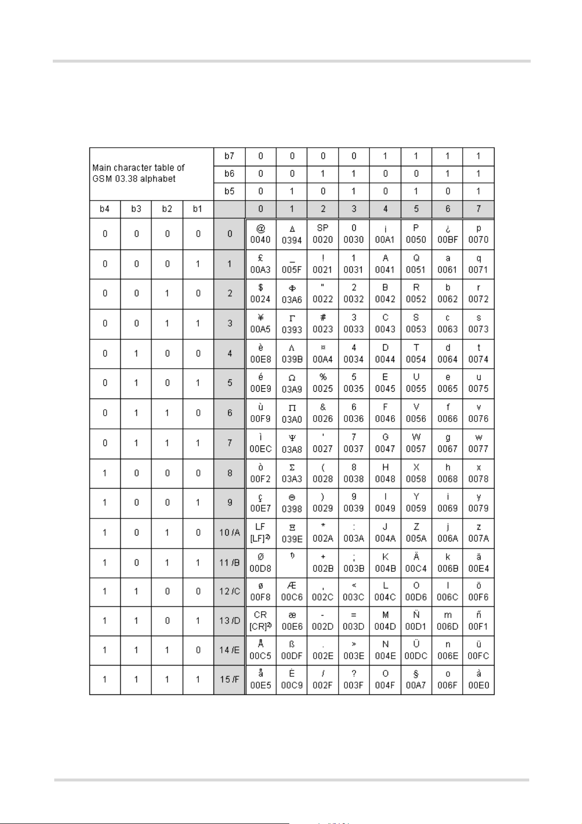
1.5.1 GSM alphabet tables and UCS2 character values
This section provides tables for the GSM 03.38 alphabet supported by the ME. Below any GSM character find
the corresponding two byte character value of the UCS2 alphabet.
Figure 1.1: Main character table of GSM 03.38 alphabet
1) This code is an escape to the following extension of the 7 bit default alphabet table.
2) This code is not a printable character and therefore not defined for the UCS2 alphabet. It shall be treated as the accompanying control character.
TC63_ATC_V00.490 Page 22 of 501 5/24/05
Confidential / Draft - Do not copy
Page 23
TC63 AT Command Set
1.5 Supported character sets
s
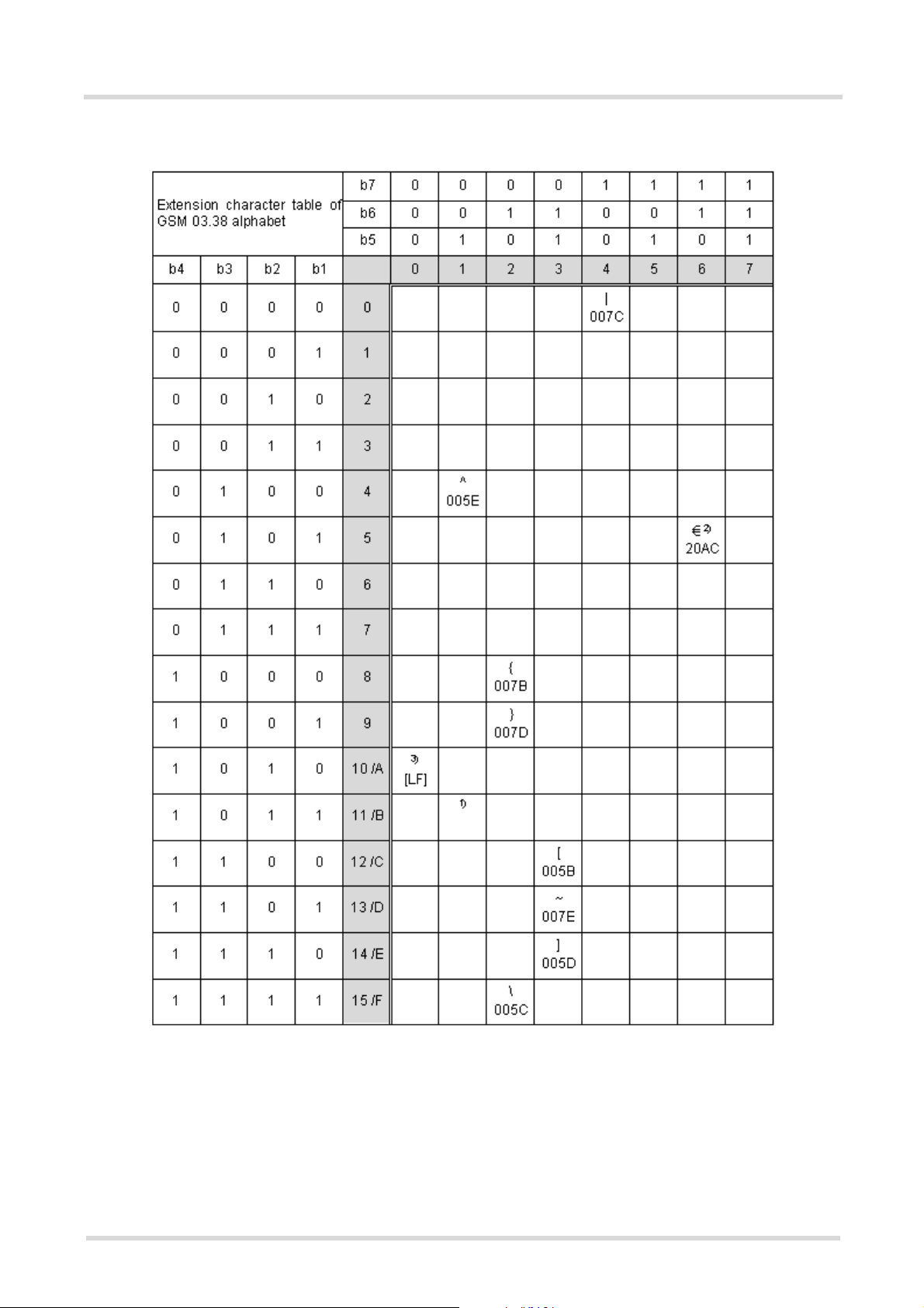
Figure 1.2: Extension character table of GSM 03.38 alphabet
1) This code value is reserved for the extension to another extension table. On receipt of this code, a receiving entity shall
display a space until another extension table is defined.
2) This code represents the EURO currency symbol. The code value is the one used for the character 'e'. Therefore a receiving entity which is incapable of displaying the EURO currency symbol will display the character 'e' instead.
3) This code is defined as a Page Break character and may be used for example in compressed CBS messages. Any mobile
which does not understand the 7 bit default alphabet table extension mechanism will treat this character as Line Feed.
TC63_ATC_V00.490 Page 23 of 501 5/24/05
Confidential / Draft - Do not copy
Page 24

TC63 AT Command Set
1.5 Supported character sets
In the event that an MS receives a code where a symbol is not represented in Figure 1.2, Extension character
table of GSM 03.38 alphabet the MS shall display the character shown in the main default 7 bit alphabet table
(see Figure 1.1, Main character table of GSM 03.38 alphabet).
s
1.5.2 UCS2 and GSM data coding and conversion for SMS text mode
This section provides basic information on how to handle input and output character conversion for SMS text
mode and Remote-SAT if internal (TA) and external (TE) character representation differ, i.e. if the Data Coding
Scheme and the TE character use different coding.
1.5.2.1 Implementing output of SIM data to Terminal (direction TA to TE)
Used character set DCS = 7 bit
GSM
GSM Case 1
GSM (1:1)
UCS2 Case 4
GSM to IRA (1:4)
Note: The ratio of SIM bytes to output bytes is given in parentheses.
Case 1
Every GSM character is sent to TE as it is (8-bit value with highest bit set to zero).
Example: 47'H, 53'H, 4D'H → 47'H, 53'H, 4D'H, displayed as "GSM"
Case 2
Every data byte will is sent to TE as 2 IRA characters each representing a halfbyte.
Example: B8'H (184 decimal) → 42'H, 38'H, displayed as "B8"
Case 3
Every 16-bit UCS2 value is sent to TE as 4 IRA characters.
Example: C4xA7'H (50343 decimal) → 43'H, 34'H, 41'H, 37'H, displayed as "C4A7"
Problem: An odd number of bytes leads to an error because there are always two bytes needed for each USC2
character
Case 4
Every GSM character is sent to TE as 4 IRA characters to show UCS2 in text mode.
Example: 41'H ("A") → 30'H, 30'H, 34'H, 31'H, displayed as "0041"
DCS = 8 bit
Data
Case 2
8 bit to IRA (1:2)
Case 5
8 bit to IRA (1:4)
DCS = 16 bit
UCS2
Case 3
UCS2 to IRA (2:4)
Case 6
UCS2 to IRA (2:4)
Case 5
Every data byte is sent to TE as IRA representation of UCS2 (similar to case 4).
Example: B2'H → 30'H, 30'H, 42'H, 32'H, displayed as "00B2"
Case 6
Every 16-bit value is sent to TE as IRA representation of it. It is assumed that number of bytes is even.
Example: C3x46'H → 43'H, 33'H, 34'H, 36'H, displayed as "C346"
TC63_ATC_V00.490 Page 24 of 501 5/24/05
Confidential / Draft - Do not copy
Page 25

TC63 AT Command Set
1.5 Supported character sets
s
1.5.2.2 Implementing input of Terminal data to SIM (direction TE to TA)
Used character set DCS = 7 bit
GSM
GSM Case 1
GSM (1:1)
UCS2 Case 4
UCS2 to GSM (4:1)
Note: The ratio between the number of input characters and bytes stored on the SIM is given in parentheses.
Case 1
Every character is sent from TE to TA as GSM character (or ASCII with Hyperterminal).
Character value must be in range from 0 to 127 because of 7-bit GSM alphabet.
To reach maximum SMS text length of 160 characters in 140 bytes space characters will be compressed on SIM.
This must be set using the parameter <dcs> of AT+CSMP (add 64).
Example: "ABCDEFGH" typed is sent and stored uncompressed as → 4142434445464748'H (stored compressed as 41E19058341E91'H)
Case 2
Every data byte is sent to TA as 2 IRA characters.
Maximum text length is 280 IRA characters which will be converted into 140 bytes SMS binary user data
Example: "C8" typed is sent as 43'H, 38'H → stored as C8'H
Case 3
Every 16-bit value is sent to TA as 4 IRA characters.
Maximum text length is 280 IRA characters which will be converted into 70 UCS2 characters (16-bit each)
Number of IRA characters must be a multiple of four because always 4 half bytes are needed for a 16-bit value
Example: "D2C8" typed is sent as 44'H, 32'H, 43'H, 38'H → stored as D2C8'H
DCS = 8 bit
Data
Case 2
IRA to 8 bit (2:1)
Case 5
UCS2 to 8 bit (4:1)
DCS = 16 bit
UCS2
Case 3
IRA to 16 bit (4:2)
Case 6
UCS2 to 16 bit (4:2)
Case 4
Every GSM character is sent to TA as 4 IRA characters representing one UCS2 character.
Example: To store text "ABC" using UCS2 character set you have to type "004100420043".
This is sent as 30'H,30'H,34'H,31'H, 30'H,30'H,34'H,32'H, 30'H,30'H,34'H,33'H → detected as IRA representation of 3 UCS2 characters, converted to GSM character set and stored as 41'H, 42'H, 43'H.
Maximum input is 640 IRA characters repesenting 160 UCS2 characters when compression is active. These are
converted to 160 GSM 7-bit characters.
Without compression only 140 GSM characters can be stored which are put in as 560 IRA characters.
Values of UCS2 characters must be smaller than 80'H (128 decimal) to be valid GSM characters.
Number of IRA characters must be a multiple of four. Problems:
• "41" → Error, there are four IRA characters (two bytes) needed
• "0000" → Error, not an UCS2 character
• "4142" → Error, value of UCS2 character > 7F'H
• "008B" → Error, value of UCS2 character > 7F'H
This affects the maximum input length of a string)
Case 5
Every UCS2 character is sent as 4 IRA characters and is converted into two 8-bit values. This means that the
first two characters have to be '00'.
Example: UCS2 character 009F'H typed as "009F" is sent as 30'H,30'H,39'H,46'H → converted into 8-bit value
9F'H.
Maximum number of UCS2 characters is 140 which are represented by 560 IRA characters. Number of IRA characters must be a multiple of four.
Case 6
Every UCS2 character is sent as 4 IRA characters each and is converted into a 16-bit value again.
Example: UCS2 character 9F3A'H typed as "9F3A" is sent as 39'H,46'H,33'H,41'H → converted into 9F3A'H.
Maximum number of UCS2 characters is 70 which are represented by 280 IRA characters. Number of IRA characters must be a multiple of four.
Invalid UCS2 values must be prevented.
TC63_ATC_V00.490 Page 25 of 501 5/24/05
Confidential / Draft - Do not copy
Page 26

TC63 AT Command Set
1.6 Serial Interface Flow Control
s
1.6 Serial Interface Flow Control
Flow control is essential to prevent loss of data or avoid errors when, in a data or fax call, the sending device is
transferring data faster than the receiving side is ready to accept. When the receiving buffer reaches its capacity,
the receiving device should be capable to cause the sending device to pause until it catches up.
There are basically two approaches to regulate data flow: Software flow control and hardware flow control. The
High Watermark of the input/output buffer should be set to approximately 60% of the total buffer size. The Low
Watermark is recommended to be about 30%. The data flow should be stopped when the capacity rises close to
the High Watermark and resumed when it drops below the Low Watermark. The time required to cause stop and
go results in a hysteresis between the High and Low Watermarks.
During Multiplex mode (AT+CMUX) it is recommended to use hardware flow control.
1.6.1 Software Flow Control (XON/OFF Handshake)
Software flow control sends different characters to stop (XOFF, decimal 19) and resume (XON, decimal 17) data
flow. The only advantage of software flow control is that three wires would be sufficient on the serial interface.
1.6.2 Hardware Flow Control (RTS/CTS Handshake)
Hardware flow control sets or resets the RTS/CTS wires. This approach is faster and more reliable, and therefore, the better choice. When the High Watermark is reached, CTS is set inactive until the transfer from the buffer
has completed. When the Low Watermark is passed, CTS goes active again.
To achieve smooth data flow, ensure that the RTS/CTS lines are present on your application platform. The application should include options to enable RTS/CTS handshake with the GSM engine. This needs to be done with
the AT command AT\Q3 - it is not sufficient to set RTS/CTS handshake in the used Terminal program only.
The default setting of the GSM engine is AT\Q0 (no flow control) which must be altered to AT\Q3 (RTS/CTS
hardware handshake on). The setting is stored volatile and must be restored each time after the GSM engine
was switched off.
AT\Q has no read command. To verify the current setting of AT\Q, simply check the settings of the active profile
with AT&V.
Often, fax programs run an intialization procedure when started up. The intialization commonly includes enabling
RTS/CTS hardware handshake, eliminating the need to set AT\Q3 once again. However, before setting up a
CSD call, you are advised to check that RTS/CTS handshake is set.
RTS/CTS hardware handshake must also be set if you want to take advantage of the CYCLIC SLEEP modes.
For further details refer to AT+CFUN.
TC63_ATC_V00.490 Page 26 of 501 5/24/05
Confidential / Draft - Do not copy
Page 27

TC63 AT Command Set
1.7 Unsolicited Result Code Presentation
s
1.7 Unsolicited Result Code Presentation
URC stands for Unsolicited Result Code and is a report message issued by the ME without being requested by
the TE, i.e. a URC is issued automatically when a certain event occurs. Hence, a URC is not issued as part of
the response related to an executed AT command.
Typical events leading to URCs are incoming calls ("RING"), waiting calls, received short messages, changes in
temperature, network registration etc.
A list of all URCs can be found in Section 21.7, Summary of Unsolicited Result Codes (URC).
To announce a pending URC transmission the ME will do the following:
• The ME activates its RING line (logic "1") for 1 second, i.e. the RING line changes to the physical "Low" level.
This allows the TE to stay in power saving mode until an ME related event requests service.
If several URCs occur coincidently or in quick succession each URC triggers the RING line independently,
although the line will not be deactivated between each URC. As a result, the RING line may stay low for more
than 1 second.
If an incoming call is answered within less than 1 second (with ATA or if autoanswering is set to ATS0=1) than
the RING line will be deactivated earlier.
The "^SHUTDOWN" will not activate the RING line.
• If the AT command interface is busy a "BREAK" will be sent immediately but the URC will not be issued until
the line is free. This may happen if the URC is pending in the following cases:
- During the processing of an AT command (i.e. the time after the TE echoes back the first character "A" of
an AT command just sent by itself until the ME responds with "OK" or "ERROR").
- During a data call.
Please note that AT command settings may be necessary to enable in-band signaling, e.g. refer to AT+CMER
or AT+CNMI.
It is strongly recommended to use the multiplex mode to map logical communication channels onto the serial line
of the TC63, for details refer to [5] and AT command AT+CMUX. Doing so it is possible to use one channel to still
process URCs while having a data call active on another.
For most of these messages, the ME needs to be configured whether or not to send a URC. Depending on the
AT command, the URC presentation mode can be saved to the user defined profile (see AT&W), or needs to be
activated every time you reboot the ME. Several URCs are not user definable, such as "^SYSSTART",
"^SYSSTART <text>", "^SHUTDOWN"
If autobauding is enabled (as factory default mode or set with AT+IPR=0), URCs generated after restart will be
output with 57600 bps until the ME has detected the current bit rate. The URCs "^SYSSTART", "^SYSSTART
<text>", however, are not presented at all. For details please refer to Section 4.9.1, Autobauding. To avoid problems we recommend to configure a fixed bit rate rather than using autobauding.
1.7.1 Communication between Customer Application and TC63
Leaving hardware flow control unconsidered the Customer Application (TE) is coupled with the TC63 (ME) via a
receive and a transmit line.
Since both lines are driven by independent devices collisions may (and will) happen, i.e. while the TE issues an
AT command the TC63 starts sending an URC. This will probably lead to the TE's misinterpretation of the URC
being part of the AT command's response.
To avoid this conflict the following measures must be taken:
• If an AT command is finished (with "OK" or "ERROR") the TE shall always wait at least 100 milliseconds
before sending the next one.
This gives the TC63 the opportunity to transmit pending URCs and get necessary service.
Note that some AT commands may require more delay after "OK" or "ERROR" response, refer to the following
command specifications for details.
• The TE shall communicate with the TC63 using activated echo (ATE1), i.e. the TC63 echoes characters
received from the TE.
Hence, when the TE receives the echo of the first character "A" of the AT command just sent by itself it has
control both over the receive and the transmit paths.
TC63_ATC_V00.490 Page 27 of 501 5/24/05
Confidential / Draft - Do not copy
Page 28

TC63 AT Command Set
1.8 Common PCN Handset Specification (CPHS)
s
1.8 Common PCN Handset Specification (CPHS)
The ME provides features to implement a device following the prerequisites of the Common PCN Handset Specification (CPHS) Phase 2.
CPHS Feature Description/Remarks AT command
Alternate Line Service Using two phone numbers with one SIM card. AT^SALS
Voice Message Waiting
Indication
Operator (Service provider) name from SIM
Network and Service Provider Lock
Call Forwarding Get and set diverted call status. Access specific Elementary
Customer Service Profile
(CSP)
Information numbers Hierarchically structured service numbers phonebook on
Indicate the receipt of a short message coded as Voice Message Waiting Indicator as defined by the CPHS Phase 2
standard.
Read specific Elementary Files (6F14h, 6F18h) from SIM. AT+CRSM
Lock/Unlock an ME to specific HPLMN and service provider. AT+CLCK,
File (6F13h) from SIM.
Setting services and their menu entries depending on cus-
tomer profiles.
SIM according to CPHS 4.2 (mandatory).
AT^SIND,
AT+CMER, indicators
"vmwait1" and
"vmwait2"
(AT+CPIN)
AT+CCFC, AT+CRSM
AT+CRSM
AT+CRSM
TC63_ATC_V00.490 Page 28 of 501 5/24/05
Confidential / Draft - Do not copy
Page 29

TC63 AT Command Set
1.9 Errors and Messages
s
1.9 Errors and Messages
The command result codes "+CME ERROR: <err>" and "+CMS ERROR: <err>" indicate errors related to mobile
equipment or network functionality.
The format of <err> can be either numeric or verbose and is selectable via AT+CMEE.
A result error code terminates the execution of the command and prevents the execution of all remaining commands that may follow on the same command line. If so, neither "ERROR" nor "OK" result codes are returned
for these commands. A 30 seconds timeout will deliver "ERROR" when the input of a command is not complete.
Using the wrong command syntax may result in errors: For example, using the execute command syntax
although the command has no execute format, causes "ERROR" to be returned. Likewise, using the write command syntax although the command has no write format causes "+CME ERROR: <err>" to be returned.
See also:
• Section 2.12.1, CME/CMS Error Code Overview
• Section 2.5.1, Verbose and numeric result codes
• Section 3.4, AT+CEER
TC63_ATC_V00.490 Page 29 of 501 5/24/05
Confidential / Draft - Do not copy
Page 30

TC63 AT Command Set
2. Configuration Commands
s
2. Configuration Commands
The AT Commands described in this chapter allow the external application to determine the TC63's behaviour
under various conditions.
2.1 AT&F Set all current parameters to manufacturer defaults
AT&F sets all current parameters to the manufacturer defined profile. All defined GPRS contexts which are not
activated or not online will be undefined (see AT+CGDCONT).
Syntax
Exec Command
AT&F[<value>]
Response(s)
OK
Reference(s) PIN ASC0 ASC1 USB MUX1 MUX2 MUX3 Charge 4 Last
V.250 ! % % % % % % ! % !
Parameter Description
<value>
[0] Set all TA parameters to manufacturer defaults
(num)
Notes
• List of parameters reset to manufacturer default can be found in Section 21.6, Factory Default Set-
tings Restorable with AT&F.
• In addition to the default profile, you can store an individual one with AT&W. To alternate between the two profiles enter either ATZ (loads user profile) or AT&F (restores factory profile).
• Every ongoing or incoming call will be terminated.
TC63_ATC_V00.490 Page 30 of 501 5/24/05
Confidential / Draft - Do not copy
Page 31

TC63 AT Command Set
2.2 AT&V
s
2.2 AT&V Display current configuration
AT&V returns the current parameter setting. The configuration varies depending on whether or not PIN authen-
tication has been done and whether or not Multiplex mode is enabled (see AT+CMUX).
Syntax
Exec Command
AT&V[<value>]
Response(s)
ACTIVE PROFILE:
... (see Section 2.2.1, AT&V responses)
OK
Reference(s) PIN ASC0 ASC1 USB MUX1 MUX2 MUX3 Charge 4 Last
V.250 ! % § % % § § ! % !
Parameter Description
<value>
[0] Profile number
(num)
Notes
• The value of \Q (flow control) is also determined by the AT+IFC command. In case the value set by AT+IFC
cannot be represented by a \Q equivalent, \Q255 will be displayed.
• The parameters of AT^SMGO can only be displayed after the SMS data from the SIM have been read successfully for the first time. Reading starts after successful SIM authentication has been performed, and may take
up to 30 seconds depending on the SIM used. While the read process is in progress, an attempt to read the
parameter will result in empty values.
• The parameter of AT+CSDH will only be displayed in SMS text mode, see AT+CMGF.
TC63_ATC_V00.490 Page 31 of 501 5/24/05
Confidential / Draft - Do not copy
Page 32

TC63 AT Command Set
2.2 AT&V
s
2.2.1 AT&V responses
The following tables show four different kinds of responses depending on whether or not the PIN is entered and
whether or not the Multiplex mode is enabled (see AT+CMUX).
Table 2.1: Current configuration on ASC0 / MUX channel 1 (example)
PIN authentication done No PIN authentication
ACTIVE PROFILE:
E1 Q0 V1 X4 &C1 &D2 &S0 \Q0 \V1
S0:000 S3:013 S4:010 S5:008 S6:000 S7:060 S8:000
S10:002 S18:000
+CBST: 7,0,1
+CRLP: 61,61,78,6
+CR: 0
+FCLASS: 0
+CRC: 0
+CMGF: 0
+CSDH: 0
+CNMI: 0,0,0,0,1
+ICF: 3
+IFC: 0,0
+ILRR: 0
+IPR: 57600
+CMEE: 2
^SMGO: 0,0
+CSMS: 0,1,1,1
^SACM: 0,"000000","000000"
^SLCC: 0
^SCKS: 0,1
^SSET: 0
+CREG: 0,1
+CLIP: 0,2
+CAOC: 0
+COPS: 0,0,"operator"
+CGSMS: 3
OK
ACTIVE PROFILE:
E1 Q0 V1 X4 &C1 &D2 &S0 \Q0 \V1
S0:000 S3:013 S4:010 S5:008 S6:000 S7:060 S8:000
S10:002 S18:000
+CBST: 7,0,1
+CRLP: 61,61,78,6
+CR: 0
+FCLASS: 0
+ICF: 3
+IFC: 0,0
+ILRR: 0
+IPR: 57600
+CMEE: 2
^SCKS: 0,1
^SSET: 0
OK
TC63_ATC_V00.490 Page 32 of 501 5/24/05
Confidential / Draft - Do not copy
Page 33

TC63 AT Command Set
2.2 AT&V
Table 2.2: Current configuration on ASC1 and MUX channels 2 and 3 (example)
PIN authentication done No PIN authentication
ACTIVE PROFILE:
E1 Q0 V1 X4 &C1 &D0 &S0 \Q0
S0:000 S3:013 S4:010 S5:008
+CR: 0
+CRC: 0
+CMGF: 0
+CSDH: 0
+CNMI: 0,0,0,0,1
+ICF: 3
+IFC: 0,0
+ILRR: 0
+IPR: 57600
+CMEE: 2
^SMGO: 0,0
+CSMS: 0,1,1,1
^SACM: 0,"000000","000000"
^SLCC: 0
^SCKS: 0,1
^SSET: 0
+CREG: 0,1
+CLIP: 0,2
+CAOC: 0
+COPS: 0,0,"operator"
+CGSMS: 3
OK
ACTIVE PROFILE:
E1 Q0 V1 X4 &C1 &D0 &S0 \Q0
S0:000 S3:013 S4:010 S5:008
+CR: 0
+ICF: 3
+IFC: 0,0
+ILRR: 0
+IPR: 57600
+CMEE: 2
^SCKS: 0,1
^SSET: 0
+CGSMS: 3
OK
s
TC63_ATC_V00.490 Page 33 of 501 5/24/05
Confidential / Draft - Do not copy
Page 34

TC63 AT Command Set
2.3 AT&W
s
2.3 AT&W Stores current configuration to user defined profile
AT&W stores the currently set parameters to a user defined profile in the non-volatile memory.
Syntax
Exec Command
AT&W[<value>]
Response(s)
OK
ERROR/+CME ERROR <err>
Reference(s) PIN ASC0 ASC1 USB MUX1 MUX2 MUX3 Charge 4 Last
V.250 ! % % % % % % ! % !
Parameter Description
<value>
[0] Number of profile
(num)
Notes
• The user defined profile will be restored automatically after power-up. Use ATZ to restore user profile and
AT&F to restore factory settings. Until the first use of AT&W, ATZ works as AT&F.
• AT&W stores all global settings and the current local settings of the interface, on which the command is executed.
• A list of parameters stored to the user profile can be found in Section 21.5, AT Command Settings stor-
able with AT&W.
TC63_ATC_V00.490 Page 34 of 501 5/24/05
Confidential / Draft - Do not copy
Page 35

TC63 AT Command Set
2.4 ATQ
s
2.4 ATQ Set result code presentation mode
This parameter setting determines whether or not the TA transmits any result code to the TE. Information text
transmitted in response is not affected by this setting.
Syntax
Exec Command
ATQ[<n>]
Response(s)
If <n>=0:
OK
If <n>=1:
(none)
Reference(s) PIN ASC0 ASC1 USB MUX1 MUX2 MUX3 Charge 4 Last
V.250 ! % % % % % % ! % !
Parameter Description
(num)(&W)(&V)
<n>
(&F)
[0]
1 Result codes are suppressed and not transmitted
DCE transmits result code
TC63_ATC_V00.490 Page 35 of 501 5/24/05
Confidential / Draft - Do not copy
Page 36

TC63 AT Command Set
2.5 ATV
s
2.5 ATV Set result code format mode
This command determines the contents of header and trailer transmitted with AT command result codes and
information responses. Possible responses are described in Section 2.5.1, Verbose and numeric result codes.
Syntax
Exec Command
ATV[<value>]
Response(s)
OK
ERROR
Reference(s) PIN ASC0 ASC1 USB MUX1 MUX2 MUX3 Charge 4 Last
V.250 ! % % % % % % ! % !
Parameter Description
<value>
[0] Information response: <text><CR><LF>
(&F)
1
(num)(&W)(&V)
Short result code format: <numeric code><CR>
Information response: <CR><LF><text><CR><LF>
Long result code format: <CR><LF><verbose code><CR>
2.5.1 Verbose and numeric result codes
Verbose format Numeric format Meaning
OK 0 Command executed, no errors
CONNECT 1 Link established
RING 2 Ring detected
NO CARRIER 3 Link not established or disconnected
ERROR 4 Invalid command or command line too long
NO DIALTONE 6 No dial tone, dialling impossible, wrong mode
BUSY 7 Remote station busy
CONNECT 2400/RLP 47 Link with 2400 bps and Radio Link Protocol
CONNECT 4800/RLP 48 Link with 4800 bps and Radio Link Protocol
CONNECT 9600/RLP 49 Link with 9600 bps and Radio Link Protocol
CONNECT 14400/RLP 50 Link with 14400 bps and Radio Link Protocol
ALERTING Alerting at called phone
DIALING Mobile phone is dialing
TC63_ATC_V00.490 Page 36 of 501 5/24/05
Confidential / Draft - Do not copy
Page 37

TC63 AT Command Set
2.6 ATX
s
2.6 ATX Set CONNECT result code format and call monitoring
ATX determines whether or not the TA detects the presence of dial tone and busy signal and whether or not TA
transmits particular result codes.
Syntax
Exec Command
ATX[<value>]
Response(s)
OK
ERROR
Reference(s) PIN ASC0 ASC1 USB MUX1 MUX2 MUX3 Charge 4 Last
V.250 ! % % % % % % ! % !
Parameter Description
<value>
[0] CONNECT result code only returned, dial tone and busy detection are both dis-
1 CONNECT <text> result code only returned, dial tone and busy detection are
2 CONNECT <text> result code returned, dial tone detection is enabled, busy
3 CONNECT <text> result code returned, dial tone detection is disabled, busy
(&F)
4
(num)(&W)(&V)
abled.
both disabled.
detection is disabled.
detection is enabled.
CONNECT <text> result code returned, dial tone and busy detection are both
enabled.
TC63_ATC_V00.490 Page 37 of 501 5/24/05
Confidential / Draft - Do not copy
Page 38

TC63 AT Command Set
2.7 AT\V
s
2.7 AT\V Set CONNECT result code format
Syntax
Exec Command
AT\V[<value>]
Response(s)
OK
ERROR
Reference(s) PIN ASC0 ASC1 USB MUX1 MUX2 MUX3 Charge 4 Last
V.250 ! % ! % % ! ! ! % !
Parameter Description
<value>
[0] CONNECT <text> result code returned without RLP trailer
(&F)
1
(num)(&W)(&V)
CONNECT <text> result code returned with RLP trailer
Notes
• For circuit switched data calls only.
• Output only if ATX parameter is set with value > 0.
TC63_ATC_V00.490 Page 38 of 501 5/24/05
Confidential / Draft - Do not copy
Page 39

TC63 AT Command Set
2.8 ATZ
s
2.8 ATZ Set all current parameters to user defined profile
ATZ sets all current parameters to the user profile stored with AT&W. If a connection is in progress, it will be ter-
minated.
All defined GPRS contexts which are not activated or not online will be undefined (see AT+CGDCONT,
AT+CGQREQ and AT+CGQMIN command).
The user defined profile is stored to the non-volatile memory.
Syntax
Exec Command
ATZ[<value>]
Response(s)
OK
Reference(s) PIN ASC0 ASC1 USB MUX1 MUX2 MUX3 Charge 4 Last
V.250 ! % % % % % % ! % !
Parameter Description
<value>
[0] Reset to user profile
(num)
Notes
• First the profile will be set to factory default (see AT&F). If there is a valid user profile (stored with AT&W), this
profile will be loaded afterwards.
• Any additional commands on the same command line may be ignored. A delay of 300 ms is required before
next command is sent, otherwise "OK" response may be corrupted.
TC63_ATC_V00.490 Page 39 of 501 5/24/05
Confidential / Draft - Do not copy
Page 40

TC63 AT Command Set
2.9 AT+CFUN
s
2.9 AT+CFUN Set phone functionality
The AT+CFUN command serves to control the functionality level of the ME. It can be used to reset the ME, to
choose one of the SLEEP modes or to return to full functionality.
Intended for power saving, SLEEP mode reduces the functionality of the ME to a minimum and thus minimizes
the current consumption. SLEEP mode falls in two categories:
• NON-CYCLIC SLEEP mode <fun>=0
• and CYCLIC SLEEP modes, selectable as <fun>= 7 or 9.
NON-CYCLIC SLEEP mode permanently blocks the serial interface. The benefit of the CYCLIC SLEEP mode is
that the serial interface remains accessible and that, in intermittent wake-up periods, characters can be sent or
received without terminating the selected mode. This allows the ME to wake up for the duration of an event and,
afterwards, to resume power saving. Please refer to Section 2.9.1, Wake up the ME from SLEEP mode for a
summary of all SLEEP modes and the different ways of waking up the module.
For CYCLIC SLEEP mode both the ME and the application must be configured to use hardware flow control.
This is necessary since the CTS signal is set/reset every 0.9-2.7 seconds in order to indicate to the application
when the UART is active. The default setting of hardware flow control is AT\Q0 which must be altered to AT\Q3.
For use after restart you are advised to add it to the user profile saved with AT&W.
If both interfaces ASC0 and ASC1 are connected, hardware flow control must be set in either application.
The AT+CFUN test command returns the values of the supported parameters.
The AT+CFUN read command returns the current functionality value.
The AT+CFUN write command can be used to reset the ME, to choose one of the SLEEP modes or to return to
full functionality.
Syntax
Test Command
AT+CFUN=?
Response(s)
+CFUN: (list of supported <fun>s) , (list of supported <rst>s)
OK
Read Command
AT+CFUN?
Response(s)
+CFUN: <fun>
OK
Write Command
AT+CFUN=[<fun>[, <rst>]]
Response(s)
OK
ERROR
+CME ERROR
Reference(s) PIN ASC0 ASC1 USB MUX1 MUX2 MUX3 Charge 4 Last
GSM 07.07 ! % % % § § § ! % !
TC63_ATC_V00.490 Page 40 of 501 5/24/05
Confidential / Draft - Do not copy
Page 41

TC63 AT Command Set
2.9 AT+CFUN
Unsolicited Result Codes
URC 1
^SYSSTART
Indicates that the ME has been started and is ready to operate. If autobauding is active (AT+IPR=0) the URC
is not generated.
If the ME is configured to enter the Airplane mode after restart or reset the following URC is received on bootup: "^SYSSTART AIRPLANE MODE". In this mode, only the AT commands listed in Section 21.4, Avail-
ability of AT Commands Depending on Operating Mode of ME can be used. For details please
refer to the AT^SCFG command, parameter <mapos>.
URC 2
^SYSSTART CHARGE ONLY MODE
Indicates that the ME has entered the CHARGE ONLY mode. This occurs if the charger is connected while
the ME is in POWER DOWN mode. If autobauding is active (AT+IPR=0) the URC is not generated. In
CHARGE ONLY mode the ME is neither registered to the GSM network nor are the serial interfaces fully
accessible. Only the AT commands listed in Section 21.4, Availability of AT Commands Depending
on Operating Mode of ME can be used. For further details on charging refer to the Hardware Interface
Description [2].
s
Parameter Description
(&F)
(num)
In this mode, the AT interface is not accessible. Consequently, after setting
<fun>=0, do not send further characters. Otherwise these characters remain
in the input buffer and may delay the output of an unsolicited result code.
Due to the fact that the serial interface is disabled, this mode cannot be used
if a Remote SIM Access (RSA) connection is ongoing (reason: during RSA
connections the SIM communication is routed via a serial channel).
The first wake-up event stops power saving and takes the ME back to full functionality level <fun>=1.
Full functionality.
If the ME is in one of the CYCLIC SLEEP modes you can issue AT+CFUN=1
to stop power saving and return to full functionality.
Keep in mind that, unlike the reset command described below, this action does
not restart the ME but only changes the level of functionality. See parameter
<rst> for details on the reset.
In this mode, the serial interface is shortly enabled while CTS is active. If characters are recognized on the serial interface, the ME stays active for 2 seconds
after the last character was sent or received. ME exits SLEEP mode only, if
AT+CFUN=1 is entered.
In this mode, the serial interface is shortly enabled while CTS is active. If characters are recognized on the serial interface, the ME stays active after the last
character was sent or received for at least the time, which can be configured
by AT^SCFG="PowerSaver/Mode9/Timeout",<psm9to> (temporary wakeup).
In contrast to SLEEP mode 7 assertion of RTS can also be used to temporarily
wake up the ME. In this case too, activity time is at least the time set with
AT^SCFG="PowerSaver/Mode9/Timeout",<psm9to>. RTS can be activated
either from ASC0 or ASC1.
ME exits SLEEP mode only, if AT+CFUN=1 is entered.
<fun>
0 NON-CYCLIC SLEEP mode:
[1]
7 CYCLIC SLEEP mode:
9 CYCLIC SLEEP mode:
TC63_ATC_V00.490 Page 41 of 501 5/24/05
Confidential / Draft - Do not copy
Page 42

TC63 AT Command Set
2.9 AT+CFUN
s
<rst>
The parameter can only be used if the serial interface is enabled.
Due to the command syntax, you need to enter parameter <fun>, followed by <rst>, where <fun> is only a
placeholder and has no effect. See examples below.
[0] Placeholder for <fun> as stated above.
1 ME resets and restarts to full functionality. After reset and restart, PIN 1
(num)
authentication is necessary (AT+CPIN). If autobauding is enabled, it is recommended to wait 3 to 5 seconds before entering the first AT command. For
details on autobauding refer to Section 4.9.1, Autobauding.
Notes
• If both serial interfaces ASC0 and ASC1 are connected, any functionality level set with AT+CFUN takes effect
on both of them. In Multiplex mode, the CFUN profile is shared by all multiplexer channels.
• If the ME is in Multiplexer mode, it is not recommended to activate SLEEP mode with AT+CFUN=<fun>. The
best approach to properly control SLEEP mode in this case is to issue the PSC messages described in [5],
Section "Power saving control".
• When a circuit-switched call is in progress, <fun>=7 or 9 can be activated without terminating the call. However, setting <fun>=0 during a circuit-switched call immediately disconnects this call.
• To check whether power saving is on, you can query the status with the read command AT+CFUN? only if
the module is in full functionality mode or in CYCLIC SLEEP mode. If available, you can also take advantage
of the status LED controlled by the SYNC pin (see AT^SSYNC and [2]). With AT^SSYNC you can select different modes of LED signalization during SLEEP modes (see Section 19.6.1, ME status indicated by status LED
patterns for details). However, the module can wake up temporarily from power saving without leaving its
CYCLIC SLEEP mode (without changing +CFUN "<fun>"), e.g. for a network scan after a loss of radio coverage, or after receipt of serial data during CYCLIC SLEEP mode. During this "temporary wakeup state" the
LED will operate as if the ME was in full functionality mode.
• Recommendation: In NON-CYCLIC SLEEP mode, you can set an RTC alarm to wake up the ME and return
to full functionality. This is a useful approach because, in this mode, the AT interface is not accessible.
2.9.1 Wake up the ME from SLEEP mode
A wake-up event is any event that causes the ME to draw more current. Depending on the selected mode, the
wake-up event either switches the SLEEP mode off and takes the ME back to full functionality AT+CFUN=1, or
activates the ME temporarily without terminating the selected SLEEP mode.
Definitions of the state transitions described in Table 2.3:
• Quit: ME exits SLEEP mode.
• Temporary: ME becomes active temporarily for the duration of the event and the mode-specific follow-up time
after the last character was sent or received on the serial interface.
• No effect: Event is not relevant in the selected SLEEP mode. The ME does not wake up.
Table 2.3: Wake-up events in NON-CYCLIC and CYCLIC SLEEP modes
Event Selected mode:
<fun>=0
Ignition line No effect No effect
/RTS0 or /RTS1 activation Quit Mode 7: No effect (RTS is only
Unsolicited Result Code (URC) Quit Temporary
Incoming voice or data call Quit Temporary
Selected mode:
<fun>=7 or 9
used for flow control)
Mode 9: Temporary
TC63_ATC_V00.490 Page 42 of 501 5/24/05
Confidential / Draft - Do not copy
Page 43

TC63 AT Command Set
2.9 AT+CFUN
s
Event Selected mode:
<fun>=0
Any AT command (incl. outgoing
SMS, voice or data call)
Incoming SMS (AT+CNMI is set to
0,0 (this is the default setting)
Incoming SMS (AT+CNMI is set to
1,1)
GPRS data transfer Not possible (UART disabled) Temporary
RTC alarm line Quit Temporary
AT+CFUN=1 Not possible (UART disabled) Quit
Not possible (UART disabled) Temporary
No effect No effect
Quit Temporary
Selected mode:
<fun>=7 or 9
TC63_ATC_V00.490 Page 43 of 501 5/24/05
Confidential / Draft - Do not copy
Page 44

TC63 AT Command Set
2.10 AT^SMSO
s
2.10 AT^SMSO Switch off mobile station
AT^SMSO initiates the power-off procedure. High level of the module's PWR_IND pin and the URC "^SHUTDOWN"
notify that the procedure has completed and the module has entered the POWER DOWN mode. Therefore, be
sure not to disconnect the operating voltage until PWR_IND is high or until the URC "^SHUTDOWN" is displayed.
Otherwise, you run the risk of losing data. For further details on how to turn off the module see the [2].
Syntax
Test Command
AT^SMSO=?
Response(s)
OK
Exec Command
AT^SMSO
Response(s)
^SMSO: MS OFF
OK
Reference(s) PIN ASC0 ASC1 USB MUX1 MUX2 MUX3 Charge 4 Last
SIEMENS ! % % % % % % ! % %
Unsolicited Result Code
^SHUTDOWN
Indicates that the power-off procedure is finished and the module will be switched off in less than 1 second.
Notes
• Do not send any other AT command after AT^SMSO.
• If AT^SMSO is entered on one of the Multiplexer channels the ME closes the Multiplexer channels, terminates
the Multiplexer and deactivates all other functions. Then, the URC "^SHUTDOWN" will be issued on the phys-
ical serial interface (ASC0). The URC will be transmitted at the bit rate last activated on ASC0 for use with
the Multiplex driver.
• If both interfaces ASC0 and ASC1 are connected the URC appears on both of them.
• If the module is in NORMAL mode and the charger is connected to the VCHARGE line, the AT^SMSO command causes the module to shut down shortly and then start into the CHARGE ONLY mode. If the module is
in CHARGE ONLY mode the AT^SMSO command is not supported at all. In both cases, the module can only
be switched off by disconnecting the charger. See also [2].
TC63_ATC_V00.490 Page 44 of 501 5/24/05
Confidential / Draft - Do not copy
Page 45

TC63 AT Command Set
2.11 AT+GCAP
s
2.11 AT+GCAP Request complete TA capabilities list
AT+GCAP returns a list of additional capabilities.
Syntax
Test Command
AT+GCAP=?
Response(s)
OK
Exec Command
AT+GCAP
Response(s)
+GCAP: <name>
OK
Reference(s) PIN ASC0 ASC1 USB MUX1 MUX2 MUX3 Charge 4 Last
V.250 ! % % % % % % ! % !
Parameter Description
<name>
e.g.: +CGSM,+FCLASS
(str)
Note
• +CGSM: The response text shows which GSM commands of the ETSI standard are supported.
TC63_ATC_V00.490 Page 45 of 501 5/24/05
Confidential / Draft - Do not copy
Page 46

TC63 AT Command Set
2.12 AT+CMEE
s
2.12 AT+CMEE Mobile Equipment Error Message Format
AT+CMEE controls the format of the error result codes that indicates errors related to TC63 functionality. Format
can be selected between plain "ERROR" output, error numbers or verbose "+CME ERROR: <err>" and "+CMS
ERROR: <err>" messages.
Possible error result codes are listed in Table 2.4, General "CME ERROR" Codes (GSM 07.07), Table 2.6,
GPRS related "CME ERROR" Codes (GSM 07.07) and Table 2.8, SMS related "CMS ERROR" Codes (GSM
07.05).
In multiplex mode (refer AT+CMUX) the setting applies only to the logical channel where selected. The setting on
the other channels may differ.
Syntax
Test Command
AT+CMEE=?
Response(s)
+CMEE: (list of supported<errMode>s)
OK
Read Command
AT+CMEE?
Response(s)
+CMEE: <errMode>
OK
Write Command
AT+CMEE=<errMode>
Response(s)
OK
ERROR
+CME ERROR: <err>
Reference(s) PIN ASC0 ASC1 USB MUX1 MUX2 MUX3 Charge 4 Last
GSM 07.07 ! % % % % % % ! % !
Parameter Description
<errMode>
(&F)(D)
0
1 Enable error result code with numeric values.
2 Enable error result code with verbose (string) values.
(num)(&W)(&V)
Disable result code, i.e. only "ERROR" will be displayed.
Example
To obtain enhanced error messages it is recommended to choose <errMode>=2.
AT+CMEE=2
OK
TC63_ATC_V00.490 Page 46 of 501 5/24/05
Confidential / Draft - Do not copy
Page 47

TC63 AT Command Set
2.12 AT+CMEE
2.12.1 CME/CMS Error Code Overview
Table 2.4: General "CME ERROR" Codes (GSM 07.07)
<err> Code Text (if AT+CMEE=2)
0 phone failure
1 no connection to phone
2 phone-adapter link reserved
3 Operation not allowed
4 Operation not supported
5 PH-SIM PIN required
6 PH-FSIM PIN required
7 PH-FSIM PUK required
10 SIM not inserted
11 SIM PIN required
12 SIM PUK required
13 SIM failure
14 SIM busy
15 SIM wrong
16 Incorrect password
17 SIM PIN2 required
18 SIM PUK2 required
20 Memory full
21 invalid index
22 not found
23 Memory failure
24 text string too long
25 invalid characters in text string
26 dial string too long
27 invalid characters in dial string
30 no network service
31 Network timeout
32 Network not allowed emergency calls only
40 Network personalization PIN required
41 Network personalization PUK required
42 Network subset personalization PIN required
43 Network subset personalization PUK required
44 service provider personalization PIN required
45 service provider personalization PUK required
46 Corporate pe sonalization PIN required
47 Corporate personalization PUK required
48 Master Phone Code required
100 unknown
132 service option not supported
s
TC63_ATC_V00.490 Page 47 of 501 5/24/05
Confidential / Draft - Do not copy
Page 48

TC63 AT Command Set
2.12 AT+CMEE
<err> Code Text (if AT+CMEE=2)
133 requested service option not subscribed
134 service option temporarily out of order
256 Operation temporary not allowed
257 call barred
258 phone is busy
259 user abort
260 invalid dial string
261 ss not executed
262 SIM blocked
263 Invalid Block
Table 2.5: General "CME ERROR" Codes (SIEMENS)
<err> Code Text (if AT+CMEE=2)
772 SIM powered down
s
Table 2.6: GPRS related "CME ERROR" Codes (GSM 07.07)
<err> Code Text (if AT+CMEE=2)
103 Illegal MS
106 Illegal ME
107 GPRS services not allowed
111 PLMN not allowed
112 Location area not allowed
113 Roaming not allowed in this location area
148 unspecified GPRS error
149 PDP authentication failure
150 invalid mobile class
Table 2.7: GPRS related "CME ERROR" Codes (SIEMENS)
<err> Code Text (if AT+CMEE=2)
578 GPRS - unspecified activation rejection
588 GPRS - feature not supported
594 GPRS - invalid address length
595 GPRS - invalid character in address string
596 GPRS - invalid cid value
607 GPRS - missing or unknown APN
625 GPRS - pdp type not supported
630 GPRS - profile (cid) not defined
632 GPRS - QOS not accepted
633 GPRS - QOS validation fail
643 GPRS - unknown PDP address or type
644 GPRS - unknown PDP context
646 GPRS - QOS invalid parameter
TC63_ATC_V00.490 Page 48 of 501 5/24/05
Confidential / Draft - Do not copy
Page 49

TC63 AT Command Set
2.12 AT+CMEE
Table 2.8: SMS related "CMS ERROR" Codes (GSM 07.05)
<err> Code Text (if AT+CMEE=2)
1 Unassigned (unallocated) number
8 Operator determined barring
10 Call barred
21 Short message transfer rejected
27 Destination out of service
28 Unidentified subscriber
29 Facility rejected
30 Unknown subscriber
38 Network out of order
41 Temporary failure
42 Congestion
47 Resources unavailable, unspecified
50 Requested facility not subscribed
69 Requested facility not implemented
81 Invalid short message transfer reference value
95 Invalid message, unspecified
96 Invalid mandatory information
97 Message type non-existent or not implemented
98 Message not compatible with short message protocol state
99 Information element non-existent or not implemented
111 Protocol error, unspecified
127 Interworking, unspecified
128 Telematic interworking not supported
129 Short message Type 0 not supported
130 Cannot replace short message
143 Unspecified TP-PID error
144 Data coding scheme (alphabet) not supported
145 Message class not supported
159 Unspecified TP-DCS error
160 Command cannot be actioned
161 Command unsupported
175 Unspecified TP-Command error
176 TPDU not supported
192 SC busy
193 No SC subscription
194 SC system failure
195 Invalid SME address
196 Destination SME barred
197 SM Rejected-Duplicate SM
198 TP-VPF not supported
199 TP-VP not supported
s
TC63_ATC_V00.490 Page 49 of 501 5/24/05
Confidential / Draft - Do not copy
Page 50

TC63 AT Command Set
2.12 AT+CMEE
<err> Code Text (if AT+CMEE=2)
208 D0 SIM SMS storage full
209 No SMS storage capability in SIM
210 Error in MS
211 Memory Capacity Exceeded
212 SIM Application Toolkit Busy
213 SIM data download error
255 Unspecified error cause
300 ME failure
301 SMS service of ME reserved
302 Operation not allowed
303 Operation not supported
304 Invalid PDU mode parameter
305 Invalid text mode parameter
310 SIM not inserted
311 SIM PIN required
312 PH-SIM PIN required
313 SIM failure
314 SIM busy
315 SIM wrong
316 SIM PUK required
317 SIM PIN2 required
318 SIM PUK2 required
320 Memory failure
321 Invalid memory index
322 Memory full
330 SMSC address unknown
331 no network service
332 Network timeout
340 NO +CNMA ACK EXPECTED
500 Unknown error
512 User abort
513 unable to store
514 invalid status
515 invalid character in address string
516 invalid length
517 invalid character in pdu
518 invalid parameter
519 invalid length or character
520 invalid character in text
521 timer expired
522 Operation temporary not allowed
s
TC63_ATC_V00.490 Page 50 of 501 5/24/05
Confidential / Draft - Do not copy
Page 51

TC63 AT Command Set
2.13 AT+CSCS
s
2.13 AT+CSCS Select TE character set
The AT+CSCS write command informs the TA which character set <chset> is used by the TE. This enables the
TA to convert character strings correctly between TE and ME character sets. See also Section 1.5, Supported
character sets.
Note that when the TA-TE interface is set to 8-bit operation and the used TE alphabet is 7-bit, the highest bit will
be set to zero.
Syntax
Test Command
AT+CSCS=?
Response(s)
+CSCS: (list of supported<chset>s)
OK
Read Command
AT+CSCS?
Response(s)
+CSCS: <chset>
OK
Write Command
AT+CSCS=[<chset>]
Response(s)
OK
Reference(s) PIN ASC0 ASC1 USB MUX1 MUX2 MUX3 Charge 4 Last
GSM 07.07, GSM 11.11 ! % % % % % % ! % !
Parameter Description
(&F)
(str)
GSM default alphabet (GSM 03.38 subclause 6.2.1);
Note: This setting may cause software flow control problems since the codes
used to stop and resume data flow (XOFF = decimal 19, XON = decimal 17)
are interpreted as normal characters.
character strings are converted to hexadecimal numbers from 0000 to FFFF;
e.g. "004100620063" equals three 16-bit characters with decimal values 65, 98
and 99, $(AT R97)$
<chset>
“GSM“
“UCS2“ 16-bit universal multiple-octet coded character set (ISO/IEC10646 [32]); UCS2
TC63_ATC_V00.490 Page 51 of 501 5/24/05
Confidential / Draft - Do not copy
Page 52

TC63 AT Command Set
2.14 AT^SCFG
s
2.14 AT^SCFG Extended Configuration Settings
AT^SCFG can be used to query and configure various settings of the TC63.
The AT^SCFG read command returns a list of all supported parameters and their current values.
The AT^SCFG write command queries a configuration parameter (if no value is entered) or sets its value(s).
Input of parameter names is always coded in GSM character set, parameter values are expected to be given as
specified via AT+CSCS.
The following error messages may be returned by the AT^SCFG write commands:
• "+CME ERROR: operation temporary not allowed"
Change of parameter value(s) temporarily not allowed.
• "+CME ERROR: invalid index"
Invalid parameter name or value(s).
• "+CME ERROR: invalid characters in text string"
Character set conversion of parameter value(s) failed.
• "+CME ERROR: memory failure"
Could not allocate necessary memory or storing a parameter failed.
• "+CME ERROR: operation not allowed"
Change of parameter value(s) not allowed
• "+CME ERROR: unknown"
Other error
Syntax
Test Command
AT^SCFG=?
Response(s)
^SCFG: "AutoExec" , (list of supported <AutoExecCmd>), (list of supported <AutoExecType>), (list of
supported <AutoExecIndex>), (list of supported <AutoExecMode>), (max. string length of
<AutoExecATC>), (time range of <AutoExecPeriod>)
^SCFG: "GPRS/ATS0/withAttach", (list of supported <gs0aa>s)
^SCFG: "GPRS/AutoAttach", (list of supported <gaa>s)
^SCFG: "GPRS/RingOnIncomingData", (list of supported <groid>s)
^SCFG: "MEopMode/Airplane", (list of supported <map>s)
^SCFG: "MEopMode/Airplane/OnStart", (list of supported <mapos>s)
^SCFG: "PowerSaver/Mode9/Timeout", (list of supported <psm9to>s)
^SCFG: "Radio/Band", (list of supported <rbp>s), (list of supported <rba>s)
^SCFG: "Radio/OutputPowerReduction", (list of supported <ropr>s)
^SCFG: "URC/CallStatus/CIEV", (list of supported <succ>s)
^SCFG: "URC/CallStatus/SLCC", (list ofsupported <sucs>s)
^SCFG: "URC/Datamode/Ringline", (list of supported <udri>s)
^SCFG: "URC/Ringline", (list of supported <uri>s)
^SCFG: "URC/Ringline/ActiveTime", (list of supported <urat>s)
OK
Read Command
AT^SCFG?
Response(s)
^SCFG: "AutoExec" , <AutoExecCmd>, <AutoExecType>, <AutoExecIndex>, <AutoExecMode>,
<AutoExecATC>[, <AutoExecPeriod>, <AutoExecPeriodTimeLeft>]
^SCFG: "GPRS/ATS0/withAttach", <gs0aa>
^SCFG: "GPRS/AutoAttach", <gaa>
^SCFG: "GPRS/RingOnIncomingData", <groid>
^SCFG: "MEopMode/Airplane", <map>
^SCFG: "MEopMode/Airplane/OnStart", <mapos>
^SCFG: "PowerSaver/Mode9/Timeout", <psm9to>
TC63_ATC_V00.490 Page 52 of 501 5/24/05
Confidential / Draft - Do not copy
Page 53

TC63 AT Command Set
2.14 AT^SCFG
Read Command (Continued)
AT^SCFG?
Response(s)
^SCFG: "Radio/Band", <rbc>, <rba>
^SCFG: "Radio/OutputPowerReduction", <ropr>
^SCFG: "URC/CallStatus/CIEV", <succ>
^SCFG: "URC/CallStatus/SLCC", <sucs>
^SCFG: "URC/Datamode/Ringline", <udri>
^SCFG: "URC/Ringline", <uri>
^SCFG: "URC/Ringline/ActiveTime", <urat>
OK
Write Command
Automatic AT command execution
AT^SCFG="AutoExec" , <AutoExecCmd>, <AutoExecType>, <AutoExecIndex>[, <AutoExecMode>,
<AutoExecATC>[, <AutoExecPeriod>]]
Response(s)
^SCFG: "AutoExec" , <AutoExecCmd>, <AutoExecType>, <AutoExecIndex>, <AutoExecMode>,
<AutoExecATC>[, <AutoExecPeriod>, <AutoExecPeriodTimeLeft>]
OK
ERROR
+CME ERROR
s
Write Command
GPRS ATS0 with automatic attach
AT^SCFG="GPRS/ATS0/withAttach"[, <gs0aa>]
Response(s)
^SCFG: "GPRS/ATS0/withAttach", <gs0aa>
OK
ERROR
+CME ERROR
Write Command
Automatic GPRS attach
AT^SCFG="GPRS/AutoAttach"[, <gaa>]
Response(s)
^SCFG: "GPRS/AutoAttach", <gaa>
OK
ERROR
+CME ERROR
Write Command
Ring on incoming GPRS IP data packets
AT^SCFG="GPRS/RingOnIncomingData"[, <groid>]
Response(s)
^SCFG: "GPRS/RingOnIncomingData", <groid>
OK
ERROR
+CME ERROR
TC63_ATC_V00.490 Page 53 of 501 5/24/05
Confidential / Draft - Do not copy
Page 54

TC63 AT Command Set
2.14 AT^SCFG
Write Command
Enable/disable Airplane mode during operation
AT^SCFG="MEopMode/Airplane"[, <map>]
Response(s)
^SCFG: "MEopMode/Airplane", <map>
OK
ERROR
+CME ERROR
Write Command
Airplane mode upon ME restart
AT^SCFG="MEopMode/Airplane/OnStart"[, <mapos>]
Response(s)
^SCFG: "MEopMode/Airplane/OnStart", <mapos>
OK
ERROR
+CME ERROR
s
Write Command
Query/Set timeout value for power saving mode 9
AT^SCFG="PowerSaver/Mode9/Timeout"[, <psm9to>]
Response(s)
^SCFG: "PowerSaver/Mode9/Timeout", <psm9to>
OK
ERROR
+CME ERROR
Write Command
Radio output power reduction
AT^SCFG="Radio/OutputPowerReduction"[, <ropr>]
Response(s)
^SCFG: "Radio/OutputPowerReduction", <ropr>
OK
ERROR
+CME ERROR
Write Command
Radio band selection
AT^SCFG="Radio/Band"[, <rbp>][, <rba>]
Response(s)
^SCFG: "Radio/Band", <rbp>, <rba>
OK
ERROR
+CME ERROR
Write Command
Configuration of URC "+CIEV: call" Call Status Indication
AT^SCFG="URC/CallStatus/CIEV"[, <succ>]
Response(s)
^SCFG: "URC/CallStatus/CIEV", <succ>
OK
ERROR
+CME ERROR
TC63_ATC_V00.490 Page 54 of 501 5/24/05
Confidential / Draft - Do not copy
Page 55

TC63 AT Command Set
2.14 AT^SCFG
Write Command
Configuration of URC "^SLCC" Call Status Indication
AT^SCFG="URC/CallStatus/SLCC"[, <sucs>]
Response(s)
^SCFG: "URC/CallStatus/SLCC", <sucs>
OK
ERROR
+CME ERROR
Write Command
URC indication in datamode via Ring line:
AT^SCFG="URC/Datamode/Ringline"[, <udri>]
Response(s)
^SCFG: "URC/Datamode/Ringline", <udri>
OK
ERROR
+CME ERROR
s
Write Command
URC indication via Ring line:
AT^SCFG="URC/Ringline"[, <uri>]
Response(s)
^SCFG: "URC/Ringline", <uri>
OK
ERROR
+CME ERROR
Write Command
Duration of active RING line for URC indications:
AT^SCFG="URC/Ringline/ActiveTime"[, <urat>]
Response(s)
^SCFG: "URC/Ringline/ActiveTime", <urat>
OK
ERROR
+CME ERROR
Unsolicited Result Codes
PIN ASC0 ASC1 USB MUX1 MUX2 MUX3 Charge 4 Last
! % % % % % % § § !
URC 1
^SCFG: "AutoExec", <AutoExecState>, <AutoExecType>, <AutoExecIndex>,
<AutoExecMode>, <AutoExecATC>
If the event specified with <AutoExecType> occurs and the related AT command line is executed this URC
is issued.
URC 2
^SYSSTART AIRPLANE MODE
This URC is issued each time the Airplane mode is activated, no matter whether Airplane mode is set with
parameter <map>="on" or <mapos>="on". The URC notifies the user that only the AT commands supported
in Airplane mode are accessible. After leaving the Airplane mode the URC "^SYSSTART" indicates that the
ME has returned to Normal mode and the full set of AT commands is accessible again.
TC63_ATC_V00.490 Page 55 of 501 5/24/05
Confidential / Draft - Do not copy
Page 56

TC63 AT Command Set
2.14 AT^SCFG
Parameter Description
s
<AutoExecCmd>
AutoExec Command
This parameter serves to switch the Autoexec function on or off.
If it is switched off (<AutoExecCmd>=0), parameters following <AutoExecIndex> are ignored and all settings
at the given index are restored to their default values.
Value will be saved while switching off the TC63 via AT commands (e.g. AT+CFUN or AT^SMSO) and restored
on next power up.
“0“ Disable automatic execution of the AT command(s) specified with <AutoEx-
“1“ Enable automatic execution of the AT command(s) specified with <AutoExe-
<AutoExecType>
AutoExec Event Type
This parameter selects the kind of event used to automatically launch the AT command(s) specified with
<AutoExecATC>.
Value will be saved while switching off the TC63 via AT commands (e.g. AT+CFUN or AT^SMSO) and restored
on next power up.
“0“ Autoexec activity is driven by ASC0 DTR line activation (OFF-ON transition).
“1“ Autoexec activity is timer driven. To specify the time span use <AutoExecPe-
(str)(+CSCS)
ecATC> at a given <AutoExecIndex>.
cATC> at a given <AutoExecIndex>. Not allowed for <AutoExecType>=0
(DTR line activation) while multiplex mode is active, refer to AT+CMUX.
(str)(+CSCS)
riod>.
<AutoExecIndex>
AutoExec Command Index
This parameter specifies the command storage index. The following table shows the index ranges supported for
each variant of <AutoExecType>.
Value will be saved while switching off the TC63 via AT commands (e.g. AT+CFUN or AT^SMSO) and restored
on next power up.
<AutoExecType> value <AutoExecType> event Valid Indices
0 Autoexec activity is driven by ASC0 DTR
1 Autoexec activity is timer driven. 0-2
<AutoExecMode>
AutoExec Command Mode
0...255
This parameter specifies details regarding the behavior of the TC63 when the AT command starts to be exe-
cuted.
Value is interpreted as a bit field, unused bits are reserved for future use (RFU) and shall be set to 0.
When a call is released by an Autoexec activity, no release indication may be issued on the first logical channel.
If during a data call the TC63 temporarily enters command mode via +++ no AT command will be executed if
<AutoExecMode> specifies 'Ignore ongoing calls'.
Value will be saved while switching off the TC63 via AT commands (e.g. AT+CFUN or AT^SMSO) and restored
on next power up.
(str)(+CSCS)
0
line activation
(str)(+CSCS)
TC63_ATC_V00.490 Page 56 of 501 5/24/05
Confidential / Draft - Do not copy
Page 57

TC63 AT Command Set
2.14 AT^SCFG
s
Bit Mask
D0
D
1
0x00
0x01
0x02
0x03
D
2
0x04 4 0: One shot action
Mask
hex
0
1
2
3
Control
dec
00: Ignore ongoing calls
01: Wait until all calls have ended
10: Dismiss any ongoing call
11: RFU
1: Periodic action (for "AutoExec/Period" only)
D3 0x08 8 RFU
D4 0x10 16 RFU
D5 0x20 32 RFU
D6 0x40 64 RFU
D7 0x80 128 RFU
<AutoExecATC>
(str)(+CSCS)
AutoExec AT command String
This parameter specifies the AT command(s) to be launched automatically. Each AT command is executed in
the same way as if it were entered online, this means that command concatenation is possible if supported by
the given commands. If serial multiplex mode is activated (AT+CMUX) the first logical channel is used, i.e. CSD
calls (data or fax) could be set up. If the TC63 is busy on the serial channel command execution will be delayed
until ongoing action is finished.
The first two characters of the automatically launched AT command shall be "at".
Please refer to examples below.
Value will be saved while switching off the TC63 via AT commands (e.g. AT+CFUN or AT^SMSO) and restored
on next power up.
<AutoExecPeriod>
(str)(+CSCS)
AutoExec Command Period
Parameter specifies the period after which <AutoExecATC> will be executed. Format is "hhh:mm:ss", where
characters indicate hours, minutes and seconds. This parameter applies to <AutoExecType>=1 only.
Value will be saved while switching off the TC63 via AT commands (e.g. AT+CFUN or AT^SMSO) and restored
on next power up.
000:00:05...240:00:00
<AutoExecPeriodTimeLeft>
(str)(+CSCS)
AutoExec Command Period Left
This parameter shows the amount of time left until <AutoExecATC> will be executed. Format is "hhh:mm:ss",
where characters indicate hours, minutes and seconds. This parameter applies to <AutoExecType>=1 only.
Due to the internal activity and network signaling an execution delay of several seconds may occur for the overall
procedure.
000:00:00...240:00:00
<AutoExecState>
(str)(+CSCS)
AutoExec Command Status
This parameter is part of the Autoexec URC which is presented when a scheduled Autoexec activity is being
performed.
“1“ The value 1 indicates that the Autoexec activity specified with <AutoExec-
ATC> is currently executed.
TC63_ATC_V00.490 Page 57 of 501 5/24/05
Confidential / Draft - Do not copy
Page 58

TC63 AT Command Set
2.14 AT^SCFG
s
<gs0aa>
(str)(+CSCS)
GPRS ATS0 with Attach
This parameter can be used to control the behaviour of ATS0.
Parameter is global for all interfaces, volatile and will not be reset by AT&F.
(P)
“on“
When the ATS0=<n> (<n>>0) command is received, the MT will attempt to perform a GPRS attach.
“off“ When the ATS0=<n> (<n>>0) command is received, the MT will not attempt to
perform a GPRS attach.
<gaa>
(str)(+CSCS)
GPRS with AutoAttach
This parameter can be used to control whether the ME will perform a GPRS attach immediately after registering
to the network or not. If the setting is changed to "enabled" and the ME is not attached yet, it will not initiate an
attach immediately but after the next registration to the network.
Parameter is global for all interfaces, non volatile and will not be reset by AT&F.
“disabled“
(D)
GPRS auto attach is disabled
“enabled“ GPRS auto attach is enabled
<groid>
(str)(+CSCS)
Ring on incoming GPRS IP data packets
This parameter can be used to control the behaviour of the RING line for incoming IP packets in GPRS online
mode.
Parameter is local for the interface, volatile and will not be reset by AT&F.
“on“ If the ME is in power saving mode 7 or 9 (see AT+CFUN) and hardware flow
control is in use (AT\Q3) and the RTS line is inactive and there are incoming
IP packets for a GPRS context which is online, then the RING line will be activated once, for a time which is configured by the parameter "URC/Ringline/
ActiveTime" (<urat>). The RING line to be used can be configured with the
parameter "URC/Ringline" (<uri>).
(P)
“off“
RING line is not activated for incoming IP packets.
<map>
(str)(+CSCS)
MEopMode/Airplane: Enable/disable Airplane mode during operation
The two parameters <map> and <mapos> can be used to enable/disable the Airplane mode. Airplane mode
shuts down the radio part of the ME (PA and receiver), causes the ME to log off from the GSM/GPRS network
and disables all AT commands whose execution requires a radio connection. A list of AT commands supported
during Airplane mode can be found in Section 21.4, Availability of AT Commands Depending on
Operating Mode of ME. The benefit of Airplane mode is that, at locations where no RF emission is allowed
(typically airplanes, hospitals etc.), the subscriber can continue using network-independent features rather than
powering off the entire device (e.g. a PDA or smartphone).
If the subscriber tries to use an AT command not available in Airplane mode the response "+CME ERROR:
Unsupported AT command" is returned.
Parameter <map> allows entering or leaving the Airplane mode any time during operation, eliminating the need
to enter the SIM PIN again. It can be used no matter whether the parameter <mapos> is "on" or "off".
Parameter <map>is global for all interfaces, volatile and will not be reset by AT&F.
“on“ Activates Airplane mode and shuts down the radio part of the ME. The URC
"^SYSSTART AIRPLANE MODE" appears.
(P)
“off“
Deactivates Airplane mode, wakes up the radio part of the ME and restores
access to network-dependent AT commands. The URC "^SYSSTART"
appears.
TC63_ATC_V00.490 Page 58 of 501 5/24/05
Confidential / Draft - Do not copy
Page 59

TC63 AT Command Set
2.14 AT^SCFG
s
<mapos>
(str)(+CSCS)
MEopMode/Airplane: Airplane mode upon ME restart
There are two ways to enter Airplane mode upon restart: One is using AT^SCFG with <mapos> as described
below.
Another approach is configuring the ME to restart into Airplane mode at a scheduled time. In this case, use the
AT+CALA command, set an alarm time and then switch the ME off. When the alarm time is reached the ME
wakes up to Airplane mode, no matter whether <mapos> was set "on" or "off".
Parameter <mapos> is global for all interfaces, non volatile and will not be reset by AT&F.
“on“ Causes the ME to enter the Airplane mode each time the ME is restarted or
reset.
After restart or reset, the URC "^SYSSTART AIRPLANE MODE" appears and
parameter <map> is "on". The SIM PIN can be entered using the AT+CPIN
command. This enables the ME to read data from the SIM and give access to
SIM PIN dependent AT commands which are available in Airplane mode, such
as phonebook commands or several SMS commands. To notify the user when
SIM data are accessible it is recommended to activate the "^SSIM READY"
URC and store its presentation mode to the user profile with AT&W.
To return from Airplane mode to Normal mode set the parameter <map> to "off"
as described above. If PIN authentication was already done, the ME will try
now to register to the GSM network.
(P)
“off“
<psm9to>
(str)(+CSCS)
Airplane mode will not be activated after ME restart or reset.
Power saving mode 9 timeout
This parameter can be used to query or configure the wake up time for power saving mode 9 (see AT+CFUN with
parameter <fun>=9). The granularity of the timeout value is 100ms (i.e. a value of 10 equal 1 second). The minimum timeout value that can be applied is 5, but accuracy is only guaranteed for timeout values greater than 20.
Parameter is global for the ME, volatile and will not be reset by AT&F.
(P)
5...20
...36000
<rba>
(str)(+CSCS)
Allowed radio band(s)
The parameters <rba>, <rbp> and <rbc> allow the subscriber to set and query preferences for selecting fre-
quency bands.
Before changing <rba> or <rbp> ensure that no network activity occurs. The write command cannot be executed when making a call, sending or receiving short messages or when the mobile is not registered, but searching for a network. Therefore, to keep track of the module's registration state when changing the band
configuration, it is recommended to activate the URC "+CREG" first (see Section 8.4, AT+CREG). For example,
the URC "+CREG: 2" indicates that the ME is in network search mode. In this mode any attempt to change the
band parameters will be rejected with ERROR.
Execution of the write command causes the ME to deregister from and re-register to the network, no matter
whether the selected <rbp> or <rba> setting really changes. In this case too, it is useful to have the URC
"+CREG" enabled.
The status of the SIM PIN authentication remains unchanged, eliminating the need to enter the SIM PIN again
after the change.
The parameter <rba> determines the maximum range of the bands allowed. The value may be one of the single
bands listed below or all valid combinations from the values 1, 2, 4 and 8. Thus, the value range of <rba> is
"1".."15". To select or deselect a band calculate the sum of the values of all desired bands and enter the resulting
value. For example, for 1800 MHz (2) and 850 MHz (8) please enter the value (10).
Parameter <rba> is global for the ME, non-volatile and will not be reset by AT&F.
“1“ GSM 900 MHz
“2“ GSM 1800 MHz
“4“ GSM 1900 MHz
TC63_ATC_V00.490 Page 59 of 501 5/24/05
Confidential / Draft - Do not copy
Page 60

TC63 AT Command Set
2.14 AT^SCFG
“8“ GSM 850 MHz
“3“ GSM 900 MHz + GSM 1800 MHz
“5“ GSM 900 MHz + GSM 1900 MHz
“10“ GSM 850 MHz + GSM 1800 MHz
“12“ GSM 850 MHz + GSM 1900 MHz
“15“ all bands
s
<rbp>
Preferred radio band(s)
The parameter <rbp> may be one of the single bands or one of the four dualband combinations listed below.
All preferred bands must be contained in the range of allowed bands (see <rba>), otherwise the write command
will return ERROR. Invalid combinations will neither be accepted, resulting in "+CME ERROR: invalid index". To
give priority to a certain single band or band combination and suppress all others simply select the same value
both for <rbp> and <rba>.
<rbp> primarily serves to trigger the network search, i.e. it is only used one time for searching and selecting a
network. As the currently used band depends on the availability of the allowed networks the value indicated by
<rbc> may be different from <rbp>. Also, next time a network search is necessary, for example after restart,
the ME will first try to reselect the network last used, which may be different from the value of <rbp> last given.
Therefore, the setting of <rbp> will not be saved.
The value range of <rbp> is "1...12", but only the bands or band selections listed below are allowed. Trying to
set an unsupported value will be denied with "ERROR". To select or deselect a band calculate the sum of the
values of all desired bands and enter the resulting value. For example, for GSM 1800 MHz (2) and GSM 850
MHz (8) please enter the value (10).
“1“ GSM 900 MHz
“2“ GSM 1800 MHz
“4“ GSM 1900 MHz
“8“ GSM 850 MHz
“3“ GSM 900 MHz + GSM 1800 MHz
“5“ GSM 900 MHz + GSM 1900 MHz
“10“ GSM 850 MHz + GSM 1800 MHz
“12“ GSM 850 MHz + GSM 1900 MHz
(str)(+CSCS)
<rbc>
Currently selected radio band(s)
The band(s) indicated with <rbc> are all allowed bands found at a location area. This means, if prompted to
select a network the ME will search for these networks only. The value can be either a single band or a dualband
combination.
<rbc> is only a response parameter returned either after sending the read command AT^SCFG? or writing
AT^SCFG="Radio/Band".
In addition to <rbc> and to allow the subscriber to be notified whenever the selected band changes it is recommended to activate the "+CIEV" (see Section 3.3, AT^SIND).
“1“ GSM 900 MHz
“2“ GSM 1800 MHz
“4“ GSM 1900 MHz
“8“ GSM 850 MHz
“3“ GSM 900 MHz + GSM 1800 MHz
“5“ GSM 900 MHz + GSM 1900 MHz
“10“ GSM 850 MHz + GSM 1800 MHz
“12“ GSM 850 MHz + GSM 1900 MHz
TC63_ATC_V00.490 Page 60 of 501 5/24/05
Confidential / Draft - Do not copy
(str)(+CSCS)
Page 61

TC63 AT Command Set
2.14 AT^SCFG
s
<ropr>
(str)(+CSCS)
Radio Output Power Reduction
According to 3GPP Rel99, output power reduction for multiple TX slots is a mandatory feature. The amount of
power reduction is configurable up to 3.0dB for 2TX, 4.8dB for 3Tx to 6dB for 4TX. To optimize heat dissipation,
power consumption and SAR values it is recommended to use full power reduction (value "3").
Parameter is global for all interfaces, volatile and will not be reset by AT&F.
“1“ Medium Reduction at GMSK (0dB for 1TX and 2TX, 1.8dB for 3TX and 3dB
reduction 4TX
“2“ Medium Reduction at GMSK (1TX 0dB, 2TX 3dB, 3TX 4.8dB and 4TX 6dB
reduction)
(P)
“3“
Maximal Reduction at GMSK (1TX 0dB, 2TX 3dB, 3TX 4.8dB and 4TX 6dB
reduction)
<succ>
(str)(+CSCS)
CIEV Call Status Indication
This parameter can be used to control the behaviour of URC "+CIEV: call". See also AT+CIND, AT+CMER and
Section 7.1, Call Status Information.
Parameter is global for all interfaces and will not be reset by AT&F.
“restricted“
(P)
URC "+CIEV: call" will be issued only when a Call Status transition ends in
state "active" or "unknown" (see Section 7.1, Call Status Information) for a call
in the list of active calls.
“verbose“ URC "+CIEV: call" will be issued when any state transition (including transi-
tions beginning or ending in state "unknown") occurs in the list of active calls,
or when a traffic channel is established.
<sucs>
(str)(+CSCS)
SLCC Call Status Indication
This parameter can be used to control the behaviour of URC "^SLCC". See also AT^SLCC and Section 7.1, Call
Status Information.
Parameter is global for all interfaces and will not be reset by AT&F.
“restricted“ URC "^SLCC" will be issued only when a Call Status transition ends in state
"active" or "unknown" (see Section 7.1, Call Status Information) for a call in the
list of active calls
“verbose“
(P)
URC "^SLCC" will be issued when any state transition (including transitions
beginning or ending in state "unknown") occurs in the list of active calls, or
when a traffic channel is established.
<uri>
(str)(+CSCS)
URC RING line
This parameter can be used to control the behaviour of the RING line to indicate URCs (both for idle interfaces
and, if configured by the parameter "URC/Datamode/Ringline", if link is reserved) and, if configured, the indicator
for incoming IP packets (see parameter "GPRS/RingOnIncomingData" (<groid>).
Parameter is local for the interface, volatile and will not be reset by AT&F.
“off“ URC is not indicated by RING.
(P)
“local“
URC will be indicated by an activated RING line of the interface on which the
URC appears
“asc0“ URC is indicated by an activated RING0 line.
TC63_ATC_V00.490 Page 61 of 501 5/24/05
Confidential / Draft - Do not copy
Page 62

TC63 AT Command Set
2.14 AT^SCFG
s
<udri>
(str)(+CSCS)
URC Datamode RING line
This parameter specifies whether RING or BREAK is used for the signaling of URCs when the TA-TE link is
reserved (e.g. during circuit-switched data calls, fax connections, in GPRS data mode or during the execution
of an AT command).
Parameter is global for all interfaces, volatile and will not be reset by AT&F.
(P)
“off“
URC will be indicated by BREAK
“on“ URC is indicated by an active RING line for a time which is configured by the
parameter "URC/Ringline/ActiveTime" (<urat>). The RING line which will be
used, can be configured by the parameter "URC/Ringline" (<uri>).
<urat>
(str)(+CSCS)
URC RING line Active Time
This parameter can be used to control how long the RING line is activated to indicate URCs (both for idle inter-
faces and, if configured by the parameter "URC/Datamode/Ringline" (<udri>), if link is reserved) and, if configured by the parameter "GPRS/RingOnIncomingData", to indicate incoming GPRS IP data packets
(<groid>).
Parameter is global for all interfaces, volatile and will not be reset by AT&F.
“0“ RING line will be activated for a time between 4.6 and 9.2 ms.
“1“ RING line will be activated for about 100ms.
(P)
“2“
RING line will be activated for about 1s.
Notes
• Any changes to parameters of the Autoexec function will be saved and restored on next power-up only when
the ME is switched off via AT commands (e.g. AT+CFUN or AT^SMSO).
• Please keep in mind, that each time the ME is restarted the timers of all autoexec actions configured with
<AutoExecType>=1 and <AutoExecPeriod> will be reinitialized and restarted. As a result, an autoexec
action configured at a time later then a scheduled automatic restart would never be executed.
• Be careful using <AutoExecType>=1 with small period values and shutdown or reset AT commands, since
only little time remains to change these settings again after TC63 restart.
• If <AutoExecATC> uses AT commands containing secret data, this information may be retrieved with
AT^SCFG?. For instance, this applies if using AT+CPIN.
• Parameters "GPRS/ATS0/withAttach" (<gs0aa>) and "GPRS/RingOnIncomingData" (<groid>) are avail-
able only for modules supporting GPRS.
Examples
EXAMPLE 1
Enable sending of a short message (SMS) on next DTR activation (OFF-ON transition). Sent SMS is
assumed to be stored at first location of storage selected with AT+CPMS and AT^SSMSS, i.e. SMS may be
sent either from SIM or ME storage.
Also refer to AT+CMSS and AT+CMGW. Since SMS transmission and ongoing calls are possible at the same
time there is no need to wait until all calls have ended (<AutoExecMode>=0).
AT+CMGF=1
OK
AT+CNMI=1,1
OK
AT+CMGD=1
OK
AT+CMGW="01522400045",145
>Test-SMS to be sent from storage!
Enable SMS text mode.
Enable "+CMTI:" URC to be indicated when a short
message is received.
Delete first SMS location.
Start writing a short message.
Enter the text of the message. Finish with CTRL-Z.
TC63_ATC_V00.490 Page 62 of 501 5/24/05
Confidential / Draft - Do not copy
Page 63

TC63 AT Command Set
2.14 AT^SCFG
s
+CMGW: 1
Confirms that message is stored to first location.
OK
AT^SCFG="AutoExec",1,0,0,0,"AT+CMSS=1"
Enable execution on next DTR activation.
^SCFG: "AutoExec","1","0","0","0","at+cmss=1"
^SCFG: "AutoExec","0","1","0","0","","000:00:00","000:00:00"
^SCFG: "AutoExec","0","1","1","0","","000:00:00","000:00:00"
^SCFG: "AutoExec","0","1","2","0","","000:00:00","000:00:00"
OK
If a DTR activation has occured the ME issues the URC "^SCFG: " followed by the response of the executed
command; the message reference in this case:
^SCFG:"AutoExec",0,0,1,0,"AT+CMSS=1"
OK
Confirms that AT+CMSS=1 has been issued.
+CMSS: 16
EXAMPLE 2
Configure TC63 to perform a reset every 10 hours. The execution of the reset command shall be deferred
until after any calls have ended.
For details regarding software controlled power down refer to AT+CFUN and AT^SMSO.
AT^SCFG="AutoExec",1,1,2,5,"AT+CFUN=0,1","010:00:00"
...
OK
After ten hours:
^SCFG:"AutoExec",1,1,2,5,"AT+CFUN=0,1"
OK
SYSSTART
Confirms that AT+CFUN=0,1 has been issued.
TC63 has restarted. Remember that the
"^SYSSTART" URC will not appear if autobauding is
enabled.
EXAMPLE 3
Switch off the ME after three minutes without restarting it.
For details regarding software controlled power down refer to AT+CFUN and AT^SMSO.
AT^SCFG="AutoExec",1,1,2,0,"AT^SMSO","000:03:00"
...
OK
After three minutes:
^SCFG:"AutoExec",0,1,2,0,"AT^SMSO"
^SMSO: MS OFF
^SHUTDOWN
Indicates that AT^SMSO was successfully executed.
The ME enters the POWER DOWN mode.
EXAMPLE 4
Deactivate a timer-driven Autoexec function configured at <AutoExecIndex> 2 (such as the periodic automatic reset or the automatic switch-off functions configured in the preceding examples):
AT^SCFG="AutoExec",0,1,2
...
OK
EXAMPLE 5
Usage of "URC/Ringline" and "URC/Datamode/Ringline":
AT+CSCS="GSM"
Switch to GSM character set.
OK
AT^SCFG?
Query all parameters.
...
^SCFG:"URC/Datamode/Ringline","off"
While the TA-TE link is reserved URCs will be indicated by BREAK.
TC63_ATC_V00.490 Page 63 of 501 5/24/05
Confidential / Draft - Do not copy
Page 64

TC63 AT Command Set
2.14 AT^SCFG
s
^SCFG:"URC/Ringline","local"
...
OK
AT^SCFG="URC/Datamode/Ringline","on"
^SCFG:"URC/Datamode/Ringline","on"
OK
AT^SCFG="URC/Ringline","asc0"
^SCFG:"URC/Ringline","asc0"
OK
AT^SCFG="URC/Datamode/Ringline","off"
^SCFG:"URC/Datamode/Ringline","off"
OK
AT^SCFG="URC/Ringline"
^SCFG:"URC/Ringline","off"
OK
URCs on this interface will be indicated by Ring line
associated to the interface (e.g. RING0 for ASC0).
While the TA-TE link is reserved URCs will be indicated by an activated "local" Ring line.
URCs on this interface will be indicated by an activated RING0 no matter whether or not the TA-TE link
is reserved.
URCs on this interface will be indicated by an activated RING0 if the TA-TE link is not reserved and by
BREAK if the TA-TE link is reserved.
Disable any Ring line indication for URCs on this
interface.
TC63_ATC_V00.490 Page 64 of 501 5/24/05
Confidential / Draft - Do not copy
Page 65

TC63 AT Command Set
2.15 AT^SM20
s
2.15 AT^SM20 Set M20 compatibility mode
M20 is an earlier, widely used SIEMENS GSM engine. The AT^SM20 command selects different modes of
responses returned upon execution of the commands ATD and sms commands like e.g. AT+CMGW. Please note
that the AT^SM20 command has no effect on any other features and is not intended to adjust other differences
between M20 and TC63.
Syntax
Test Command
AT^SM20=?
Response(s)
OK
Read Command
AT^SM20?
Response(s)
^SM20:<CallMode>, <CmgwMode>
OK
Write Command
AT^SM20=<CallMode>[, <CmgwMode>]
Response(s)
OK
Reference(s) PIN ASC0 ASC1 USB MUX1 MUX2 MUX3 Charge 4 Last
SIEMENS ! % % % % % % ! ! !
Parameter Description
<CallMode>
Call setup response mode
Applies only to voice calls.
0 Set compatibility to Siemens mobile phones.
(&F)
1
<CmgwMode>
Response mode for sending and writing short messages
Applies to the sms commands like e.g. AT+CMGS and AT+CMGW command.
0 Set compatibility to Siemens mobile phones.
(&F)
1
(num)
ME will return "OK" immediately after attempting a call with the ATD command.
In case of failure, additional call release indications, such as "NO DIAL TONE,
"NO CARRIER", "BUSY" will follow.
Default call setup mode, compatible to M20.
ME will return "OK" in case of a successful connection, otherwise one of the
call release indications "NO DIAL TONE, "NO CARRIER", "BUSY" are indicated.
(num)
ME will return +CMS ERROR: <err> when writing or sending of short messages fails.
Default mode for sending and writing short messages, compatible to M20.
ME will return "OK", no matter whether or not sms command was successfully
executed.
TC63_ATC_V00.490 Page 65 of 501 5/24/05
Confidential / Draft - Do not copy
Page 66

TC63 AT Command Set
3. Status Control Commands
s
3. Status Control Commands
The AT Commands described in this chapter allow the external application to obtain various status information
from the TC63.
3.1 AT+CMER Mobile Equipment Event Reporting
This command controls details of the "+CIEV" URC presentation related to AT^SIND and AT+CIND. If registered
via these commands the URCs are sent whenever a value of the related indicator changes.
In addition, AT+CMER controls "^SLCC" URCs related to AT^SLCC. For details refer to Call Status Infor-
mation, AT^SLCC and AT^SCFG, parameter <sucs>.
The read command returns the URC presentation mode <mode> and among others, the indicator event reporting
status <ind>.
The write command enables and disables the presentation of "+CIEV: <indDescr>, <indValue>
Value>
is the new value of this indicator. After AT+CMER has been switched on, URCs for all registered indicators will be
issued. See examples provided in Section 3.2, AT+CIND and Section 3.3, AT^SIND.
][, <indValue>[,...]]" URCs. <indDescr> refers to the name of a "+CIEV" indicator and <indValue>
2
[, <ind-
1
Syntax
Test Command
AT+CMER=?
Response(s)
+CMER: (list of supported<mode>s), (list of supported <keyp>s), (list of supported <disp>s), (list of
supported <ind>s), (list of supported <bfr>s)
OK
Read Command
AT+CMER?
Response(s)
+CMER: <mode>, <keyp>, <disp>, <ind>, <bfr>
OK
Write Command
AT+CMER=[<mode>[, <keyp>[, <disp>[, <ind>[, <bfr>]]]]]
Response(s)
OK
ERROR
+CME ERROR
Reference(s) PIN ASC0 ASC1 USB MUX1 MUX2 MUX3 Charge 4 Last
GSM 07.07 ! % % % % % % ! % !
Unsolicited Result Code
+CIEV: <indDescr>, <indValue>1[, <indValue>2][, <indValue>[,...]]
A value of an indicator has changed. For more details see AT^SIND.
TC63_ATC_V00.490 Page 66 of 501 5/24/05
Confidential / Draft - Do not copy
Page 67

TC63 AT Command Set
3.1 AT+CMER
Parameter Description
s
<mode>
(&F)
0
(num)
Discard "+CIEV" and "^SLCC" URCs.
1 Discard "+CIEV" and "^SLCC" URCs when TA-TE link is reserved, e.g. in
online data mode. Otherwise they are forwarded directly to the TE.
2 Buffer "+CIEV" and "^SLCC" URCs in the TA while TA-TE link is reserved, e.g.
in online data mode, and flush them to the TE afterwards. Otherwise they are
forwarded directly to the TE.
3Forward "+CIEV" and "^SLCC" URCs directly to the TE. If TC63 is in online
data mode, URCs are signaled via sending BREAK (100ms) and stored in a
buffer. Once it is back in command mode e.g. after +++ was entered, all URCs
stored in the buffer will be output.
<keyp>
(&F)
0
<disp>
(&F)
0
<ind>
(&F)
0
(num)
Keypad event reporting is not supported by TC63.
(num)
Display event reporting is not supported by TC63.
(num)
Disable indicator event reporting.
2 Enable indicator event reporting.
(&F)
(num)
TA buffer of URCs defined within this command is cleared when <mode> 1..3
<bfr>
0
is entered.
<indDescr>
(str)
Name of indicator; for a list of all supported indicators please refer to AT+CIND and AT^SIND.
<indValue>
(num)
Value of indicator; for a list of all values for the supported indicators please refer to AT+CIND and AT^SIND.
Note
• If the ME operates on different instances (MUX channels 1, 2, 3 or ASC0/ASC1) avoid different settings for
routing and indicating SMS. For example, if messages shall be routed directly to one instance of the TE (set
with AT+CNMI, AT^SSDA), it is not possible to activate the presentation of URCs with AT+CMER or AT+CNMI
on another instance. Any attempt to activate settings that conflict with existing settings on another interface,
will result in CME ERROR, or accordingly CMS ERROR.
TC63_ATC_V00.490 Page 67 of 501 5/24/05
Confidential / Draft - Do not copy
Page 68

TC63 AT Command Set
3.2 AT+CIND
s
3.2 AT+CIND Indicator control
The AT+CIND command controls the presentation of Indicator Event Reports related to various functions such
as battery charge level, signal quality, service availability, sound generation, indication of unread short messages, full SMS storage, call in progress or roaming activities.
Use of AT+CIND has become outdated. Rather we recommend the more powerful AT^SIND command which is
easier to use and provides additional indicators. All indicators provided by AT+CIND can be handled with
AT^SIND as well.
AT+CIND supports two ways to get the values related to indicators:
• One approach is to query the current status of each indicator by using the read command AT+CIND?. It
returns the status no matter whether the indicator has been registered with the write command
AT+CIND=[<mode>[,<mode>[,...]]].
• The other way is an event-driven notification based on the "+CIEV" URCs. In this case, the ME will automatically send a message to the application, whenever the value of an indicator changes. The application should
be designed to react adequately when receiving a URC.
The presentation of these URCs depends on two settings:
- The indicators must be registered with the write command AT+CIND=[<mode>[,<mode>[,...]]]. When the
ME is switched on all of them are in registered mode. Any indicator can be excluded if deregistered with
<mode>=0. To register or deregister an indicator the AT+CIND write command requires to type the value
<mode>=1 or 0 exactly at the position where the indicator is located in the list. This is not necessary with
AT^SIND which allows to specify indicators by name. See examples below.
- The presentation of the registered indicators must be enabled with AT+CMER.
Syntax
Test Command
AT+CIND=?
Response(s)
+CIND: (<indDescr>, list of supported <indValue>s)[, (<indDescr>, list of supported <indValue>s)[,
...]]
OK
Read Command
AT+CIND?
Response(s)
+CIND: <indValue>[, <indValue>[, ...]]
OK
ERROR
+CME ERROR: <err>
Write Command
AT+CIND=<mode>[, <mode>[, ...]]
Response(s)
OK
ERROR
+CME ERROR: <err>
Reference(s) PIN ASC0 ASC1 USB MUX1 MUX2 MUX3 Charge 4 Last
GSM 07.07 ! % % % % % % ! % !
Parameter Description
<indValue>
Integer type value, which shall be in range of corresponding <indDescr>
TC63_ATC_V00.490 Page 68 of 501 5/24/05
Confidential / Draft - Do not copy
(num)
Page 69

TC63 AT Command Set
3.2 AT+CIND
s
<indDescr>
String values and their <indValue> ranges.
More indications are available via AT^SIND. Therefore use of AT^SIND for control of all indications is recommended.
The following indications are accessible via AT+CIND:
“battchg“ Battery charge level 0..4 or 5 if no measuring is performed, e.g because no bat-
“signal“ Signal quality (0..7)
“service“ Service availability (0-1)
“sounder“ Sounder activity (0-1)
“message“ Unread short message at memory location <mem1> (0-1); refer to AT+CPMS
“call“ Call in progress (0-1). Indicator value is "1" if at least one call is in state "active"
“roam“ Roaming indicator (0-1)
“smsfull“ A short message memory storage in the MT has become full (1) or memory
“rssi“ Received signal (field) strength (0..5)
(str)
tery is connected. Also refer to AT^SBC.
The indicated value is the bit error rate of the signal received. Bit errors are estimated values. See also AT+CSQ.
0: Not registered to any network
1: Registered to home network or, if "roam"=1 then registered to another network
Reports every event that causes the ME to generate a tone.
Value 1 means for example:
Incoming call - ME is ringing. Note that the URC "+CIEV: sounder" will be output only if ringing tones are activated with AT^SRTC.
Waiting call - ME generates waiting call tone (if call waiting is enabled).
Outgoing call - ME generates Call Progress tone.
Outgoing call - ME generates BUSY tone.
The value changes to 0 when the tone stops.
or "held".
Depending on the parameter <succ> selected with AT^SCFG the indicator
"call" will be issued
• when a state transition ends in state "active" or state "unknown", if
<succ>="restricted",
• when any state transition (including transitions beginning or ending in state
"unknown") occurs in the list of active calls or when a traffic channel is
established, if <succ>="verbose".
Also refer to Section 7.1, Call Status Information.
0: Registered to home network or not registered
1: Registered to other network
locations are available (0), i.e. range is (0-1)
0: signal strength <= -112 dbm
1-4: signal strength in 15 dbm steps
5: signal strength >= -51 dbm
Received signal (field) strength can also be obtained with AT+CSQ. However,
the signal strength is scaled to value range 0..31 by this command.
(&F)(P)
(num)
but can be queried with AT+CIND?.
Indicator is registered, indicator event report allowed.
<mode>
0 Indicator is deregistered. The indicator will not be presented as "+CIEV" URC,
[1]
TC63_ATC_V00.490 Page 69 of 501 5/24/05
Confidential / Draft - Do not copy
Page 70

TC63 AT Command Set
3.2 AT+CIND
Notes
• Due to its restrictive value range, indicator "call" does not clearly reflect specific call states (such as alerting,
active, held etc.), but rather serves to trigger the application to retrieve the new call status from the list of current calls with the AT commands AT^SLCC, AT+CLCC or AT^SCNI.
• If AT^SCFG setting <succ>="verbose", indicator "call" will be issued also when a traffic channel is established, or when a call enters states "terminating" or "dropped" (see Call Status Information).
In these cases, the relevant information about the cause of the display is available only from AT command
AT^SLCC.
Examples
EXAMPLE 1
^SYSSTART
AT+CPIN=9999
OK
AT+CIND?
+CIND: 5,0,1,0,0,0,0,0
OK
AT+CMER=2,0,0,2
OK
+CIEV: battchg,5
+CIEV: signal,0
+CIEV: service,1
+CIEV: sounder,0
+CIEV: message,0
+CIEV: call,0
+CIEV: roam,0
+CIEV: smsfull,0
+CIEV: rssi,5
ATD0123456;
OK
+CIEV: sounder,1
+CIEV: call,1
+CIEV: sounder,0
+CIEV: call,0
NO CARRIER
AT+CIND=,,,0,,0
OK
ATD0123456;
OK
NO CARRIER
EXAMPLE 2
Deactivation of indicator "sounder" via AT+CIND
AT+CIND?
+CIND: 5,0,1,0,1,0,0,0,4
OK
AT+CIND=,,,0
OK
EXAMPLE 3
Deactivation of indicator "sounder" via AT^SIND
AT^SIND="sounder",0
^SIND: sounder,0,0
OK
The battery is either full or no battery is connected to the ME. The bit
error rate of the signal quality is not available (since there is no call in
progress). The ME is registered to its home network.
Now activate the Indicator Event Report with AT+CMER.
Full receive signal strength.
Make a call.
A set of "+CIEV" URCs is received.
Called party hangs up.
Deregister the indicators "sounder" and "call".
Dial the same call.
This time, no URCs are displayed.
Called party hangs up.
Query the current status of indicators.
To deactivate indicator "sounder" (= fourth item in list of indicators).
To deactivate indicator "sounder".
s
TC63_ATC_V00.490 Page 70 of 501 5/24/05
Confidential / Draft - Do not copy
Page 71

TC63 AT Command Set
3.3 AT^SIND
s
3.3 AT^SIND Extended Indicator Control
Designed for extended event indicator control AT^SIND
• offers greater flexibility than the standard command AT+CIND,
• offers several extra indicators,
• can show the current status of all indicators supported by AT+CIND and AT^SIND,
• can be used to register or deregister the indicators of both commands,
• displays all indicator event reports via "+CIEV" URCs.
Presentation mode of the generated URCs is controlled via AT+CMER.
The AT^SIND read command provides a list of all indicators supported by AT+CIND and AT^SIND. Each indicator is represented with its registration mode and current value.
The AT^SIND write command can be used to select a single indicator in order to modify its registration and to
view the current value.
Syntax
Test Command
AT^SIND=?
Response(s)
^SIND: (<indDescr>, list of supported <indValue>s)[, (<indDescr>, list of supported <indValue>s)[,
...]], (list of supported <mode>s)
OK
Read Command
AT^SIND?
Response(s)
^SIND: <indDescr>, <mode>, <indValue>
[^SIND: <indDescr>, <mode>, <indValue>]
...
OK
ERROR
+CME ERROR: <err>
Write Command
AT^SIND=<indDescr>, <mode>
Response(s)
^SIND: <indDescr>, <mode>, <indValue>
In case of: <indDescr>="eons" and <mode>=2
^SIND: <indDescr>, <mode>, <indValue>, <eonsOperator>, <servProvider>
In case of: <indDescr>="nitz" and <mode>=2
^SIND: <indDescr>, <mode>, <nitzUT>, <nitzTZ>, <nitzDST>
OK
ERROR
+CME ERROR: <err>
Reference(s) PIN ASC0 ASC1 USB MUX1 MUX2 MUX3 Charge 4 Last
SIEMENS ! % % % % % % ! % !
TC63_ATC_V00.490 Page 71 of 501 5/24/05
Confidential / Draft - Do not copy
Page 72

TC63 AT Command Set
3.3 AT^SIND
Unsolicited Result Codes
URC 1
Format of the standard indicator:
+CIEV: <indDescr>, <indValue>
Value related to an indicator has changed.
URC 2
Format of the "adnread" indicator issued when accessing the ADN phonebook records stored on the SIM:
+CIEV: <indDescr>, <adnEntry>, <adnNumber>, <adnType>, <adnText>
+CIEV: <indDescr>, "READY"
One URC is issued for every used Abbreviated Dialing Number (ADN) phonebook record. After the last record
of the ADN phonebook was read, a URC with "READY" tag signals end of processing.
URC 3
Format of the Voice Message indicator, if the number of waiting messages is delivered by the network:
+CIEV: <indDescr>, <indValue>, <vmCounter>
If the number of waiting messages is not delivered the standard indicator applies.
s
URC 4
Format of the "eons" indicator:
+CIEV: <indDescr>, <indValue>, <eonsOperator>, <servProvider>
One URC is issued for each new LAI (Location Area Information) broadcast by the network.
URC 5
Format of the "nitz" indicator:
+CIEV: <indDescr>, <nitzUT>, <nitzTZ>, <nitzDST>
Parameter Description
<indDescr>
String values and their <indValue> ranges.
All indicators supported by AT+CIND are accessible with this command, too. A detailed description of these indicators can be found there.
The following indicators are accessible via AT^SIND only:
“audio“ Activity of the built-in audio unit.
“vmwait1“ Voice Message Waiting Indication for line 1
(str)
0 Audio unit not active.
1 Value 1 means for example:
Outgoing voice call: Indicator appears when dialing starts.
Incoming voice call: Indicator appears prior to the RING result code.
0 The value 0 notifies that no new voice message is available, and is pro-
vided by the service center to clear the voice message indication after
the subscriber has retrieved all voice messages.
1 The value 1 notifies the subscriber that the mailbox contains one or
several messages.
"vmwait1" and "vmwait2" indicate the receipt of a special short message with
a Voice Message Waiting Indicator. The service must be provisioned by the
operator.
The numbers 1 or 2 in "vmwait1" and "vmwait2" are related to the two lines of
the Alternate Line Service (ALS), also defined in CPHS Phase 2 standard. For
further details refer to the AT^SALS command.
The presentation mode of the indicator varies with the operator: If more than
one message are waiting, some operators only indicate the first one, others
deliver the indicator each time a new voice message is put into the mailbox.
TC63_ATC_V00.490 Page 72 of 501 5/24/05
Confidential / Draft - Do not copy
Page 73

TC63 AT Command Set
3.3 AT^SIND
After the subscriber has retrieved all voice messages the service center automatically sends another message indication which provides the value 0.
Some operators may also send the number of waiting voice messages along
with the indication. In this case, the number will be displayed by the TC63 as
part of the URC. For example, "+CIEV: vmwait1,1,5" notifies that five new voice
messages are waiting. However, it should be noted that neither the read command AT^SIND? nor the write command AT^SIND=<mode>,2 display the
number of waiting messages.
The "vmwait" indicators do not apply if a network provider signals new voice
mail(s) via standard SMS. In this case the indicator "message" will be displayed
(see AT+CIND).
“vmwait2“ Voice Message Waiting Indication for line 2
0 See description of "vmwait1".
1 See description of "vmwait1".
“ciphcall“ Ciphering Status Change Indication
0 Current call or SMS is not ciphered.
1 Current call or SMS is ciphered.
As stated in GSM specifications 02.07 and 02.09 the ciphering indicator feature
allows the TC63 to detect that ciphering is not switched on and to indicate this
to the user.
The ciphering indicator feature may be disabled by the home network operator
setting data in the "administrative data" field (EF
GSM 11.11.
If this feature is not disabled by the SIM, then whenever a connection is in
place, which is, or becomes unenciphered, an indication shall be given to the
user. This enables the user's decision how to proceed.
Read command returns valid ciphering status only if a call is in progress or
active.
If EF
indicates a ciphered link and no URC presentaion will take place.
The following restrictions apply if the same serial channel is used for AT^SIND
"ciphcall" indication and for the action triggering this URC. In general, the recommended solution is to use a dedicated channel for all status signalling via
URCs.
• If an unciphered mobile originated SMS is performed, AT^SIND "ciphcall"
• If an unciphered mobile originated data call is performed, AT^SIND "ciph-
setting disables the ciphering indicator feature read command always
AD
URCs on the same serial channel will be issued after the related "OK" and
indicate the ciphering state at this time.
call" URCs on the same serial channel will be issued after the interface is
not longer blocked by the call (call is released or temporarily stopped) and
indicate the ciphering state at this time.
s
) in the SIM, as defined in
AD
“adnread“ Abbreviated Dialing Number (ADN) Phonebook Read Indication
0 Phonebook reading is not finished.
1 Phonebook reading is finished.
Every time after entering the AT+CPIN the module starts reading the ADN
phonebook. This can be used to enable the TE to output the phonebook
records as URCs. The advantage is that the user does not need to wait until
the phonebook read command AT+CPBR is accessible after entering the SIM
PIN (depending on the SIM card this may take up to 30 seconds without RSA
or 2 minutes with RSA).
If <mode>=1 all used ADN phonebook records stored on the SIM will be output
as URCs after SIM PIN authentication has been performed successfully. A
URC with "READY" tag issued at the end of the list indicates that TC63 has finished reading the phonebook.
Note that the settings of AT^SIND and AT+CMER will be restored to their default
values when restarting the TC63. Therefore it is recommended that the settings be enabled before entering the SIM PIN. This can be done, for example,
after rebooting the TC63.
TC63_ATC_V00.490 Page 73 of 501 5/24/05
Confidential / Draft - Do not copy
Page 74

TC63 AT Command Set
3.3 AT^SIND
“eons“ Enhanced Operator Name String (EONS) Indication
The Enhanced Operator Name String indicator feature allows the TC63 to output various operator names for different PLMN identities via URC. It also allows
the output of a different operator name based on a subset of the registered network by using a range of Location Area Codes (LACs) or a single LAC.
The presentation of the "eons" indicator is determined by network activity. For
example, the indicator appears every time a location update occurs or a NITZ
information is sent, no matter whether or not the status of the EONS information has changed. This means that the same EONS information may be
reported several times.
The EONS tables are stored in the SIM card and will be read at power-up.
Following are the SIM Elementary Files that are affected by the introduction of
EONS feature in the SIM card:
EF
(SIM Service Table) - describes which features are active.
SST
EF
(Operator PLMN List) - contains the PLMN identification and location ID
OPL
together with the index of the corresponding PNN record
EF
(PLMN Network Name) - contains the full and short form version of the
PNN
network name for the registered PLMN
If the Operator Name Source is CPHS Operator Name String long and short
form, refer to <indValue>, the following two SIM Elementary Files will be
used:
EF
who issued the SIM.
EF
the PLMN operator who issued the SIM.
(Operator Name String) - contains the name of the PLMN operator
ONString
(Operator Name Short form) - contains a short form of the name of
OPShort
s
“nitz“ Network Identity and Time Zone indication
This indicator shows the time relevant information elements of an MM Information (MMI) or GMM Information (GMMI) message received from the network
(see GSM 24.008, ch. 9.2.15a and 9.4.19). The network usually sends a NITZ
indicator when the mobile attaches to the network, when it enters a location
area with different time zone or when a daylight change occurs.
A NITZ indicator may consist of the following parameters: Universal Time (UT),
local Time Zone (TZ), Daylight Saving Time (DST). All information elements of
MMI/GMMI are optional and therefore, the presentation of the parameters
<nitzUT>, <nitzTZ>, <nitzDST> varies with the network. For example, the
network may send all three parameters UT, TZ, DST, or only UT and TZ or only
TZ.
UT is indicated in usual date/time format and represents the current world time
(GMT) at the moment when sent.
TZ is given as a positive (east) or negative (west) offset from UT in units of 15
minutes.
DST shows the number of hours added to the local TZ because of daylight saving time (summertime) adjustment. Usually DST is 1 hour but it can be also 2
hours in certain locations.
Example for time and time zone with DST:
+CIEV: nitz,"04/07/23,13:39:20",-28,1
In this example TZ is -28, showing a time offset of -7 hours (west) to Universal
Time/GMT (which never changes for DST). DST is 1 which indicates that one
hour was added to TZ because of Daylight Saving Time. If a network does not
send the DST parameter the TZ value would be -32 (8 hours west) as would
be done in winter:
+CIEV: nitz,"04/11/23,13:39:20",-32
Please be aware that despite the last NITZ value can be looked up again via
"AT^SIND=nitz,2" the returned values may be out of date. Especially the UT
value is obsolete because there is no internal NITZ clock and therefore no continuation of UT.
NITZ values are lost when the module detaches from network. Also when a
TC63_ATC_V00.490 Page 74 of 501 5/24/05
Confidential / Draft - Do not copy
Page 75

TC63 AT Command Set
3.3 AT^SIND
manual network selection fails and the module automatically falls back to the
previous network the NITZ values cannot be recalled. Nevertheless an indicated time zone is valid until a new MMI/GMMI will trigger another NITZ indication.
“band“ Currently selected frequency band or band combination.
1...14 Identical with <rbc> of AT^SCFG. The value indicates the band(s) cur-
rently available for network selection, depending on the network config-
uration either a single band or a dualband combination. The URC
appears whenever the status of the currently available band(s)
changes, for example after using the AT^SCFG command to change
the "Radio/Band" parameters <rba> or <rbp>. Please see AT^SCFG
for further detail about the feature "Radio/Band" selection.
s
<indValue>
Integer type value in the range stated above for the corresponding <indDescr>.
Notes specific to the EONS feature:
If the indicator is "eons", the <indValue> is a type associated to the operator name according to GSM 22.101
[25]. This type depends on the source of the operator name.
Priority of types associated to the operator names is defined as follows (the type listed first has the highest priority). If a type cannot be indicated the next one will be used.
0 Not registered.
1 EF-OPL and EF-PNN (alphanumeric format, can contain up to 24 characters.)
2 Operator Name String in long and short format according to Common PCN
3 Name information received by the NITZ service long and short form (alphanu-
4 Any operator name stored internal to the ME (alphanumeric format, can con-
5 Broadcast MCC-MNC (numeric format which consists of a 3-digit country code
The name information received by the NITZ service (type 3) will be saved in the non-volatile RAM. It replaces
the operator name of the registered PLMN (type 4) or its numeric form (type 5) stored in the ME. However, when
after restart the ME registers to another PLMN that is not equal to the saved NITZ name information, the NITZ
name information must be invalidated.
If the type is 2, 4 or 5, AT+COPS with the appropriate <mode> displays the same operator name.
(num)
Handset Specification (CPHS) [26] (alphanumeric format, can contain up to 16
characters).
meric format, can contain up to 16 characters). The short form will be displayed
only if EF
tain up to 16 characters).
plus a 2- or 3-digit network code).
from CPHS is available.
OPShort
<mode>
0 Indicator is deregistered, i.e. no such indicator event report (URC) will be
1 Indicator is registered.
2 Query the registration status and the current value of a single indicator type.
<adnEntry>
ADN phonebook record number on the SIM.
TC63_ATC_V00.490 Page 75 of 501 5/24/05
Confidential / Draft - Do not copy
(num)
issued. <mode>=0 is power-up and factory default of indicators defined by
AT^SIND only.
• Indicator event reports are controlled via AT+CMER.
• All indicators can be registered or deregistered via AT^SIND, but different
default settings apply: Power-up and factory default of the indicators supported by AT+CIND is <mode>=1, while, as stated above, indicators defined
by AT^SIND only are set to <mode>=0.
(num)
Page 76

TC63 AT Command Set
3.3 AT^SIND
s
<adnNumber>
Phone number, for further details see AT+CPBR.
<adnType>
Address type, for further details see AT+CPBR.
145 Dialing string <adnNumber> includes international access code character '+'.
209 Dialing string <adnNumber> contains printable non-alphabetic non-digit char-
129 otherwise
<adnText>
Text assigned to a phone number. For further details see AT+CPBR.
<vmCounter>
If delivered by the network: Number of new voice messages sent as part of the Voice Message Waiting Indicator.
Refer to <indDescr>.
<eonsOperator>
Operator in format which depends on the type associated to the operator name. Refer to <indValue>.
(str)
(num)
acters saved with the number string.
(str)
<servProvider>
Service Provider Name according to the status settings (SIM Service No. 17) in the SIM Service Table (SST) of
the SIM.
<nitzUT>
Universal Time delivered as part of the "nitz" Indicator. Refer to <indDescr>.
<nitzTZ>
Time Zone delivered as part of the "nitz" Indicator. Refer to <indDescr>.
<nitzDST>
Adjustment for Daylight Saving Time as part of the "nitz" Indicator. Refer to <indDescr>.
(str)
Example
Activation and use of indicator "audio":
AT^SIND="audio",1
^SIND: audio,1,0
OK
AT+CMER=2,,,2
OK
+CIEV: battchg,5
+CIEV: signal,99
+CIEV: service,1
+CIEV: sounder,0
+CIEV: message,1
You register the indicator "audio".
You activate the Indicator Event Report with AT+CMER.
A set of all registered URCs is presented. (Please note that the example
includes the indicators registered due to the power-up default settings
of AT+CIND.)
TC63_ATC_V00.490 Page 76 of 501 5/24/05
Confidential / Draft - Do not copy
Page 77

TC63 AT Command Set
3.3 AT^SIND
+CIEV: call,0
+CIEV: roam,0
+CIEV: smsfull,0
+CIEV: rssi,4
+CIEV: audio,0
ATD030123456
OK
+CIEV: audio,1
+CIEV: sounder,1
+CIEV: call,1
+CIEV: signal,0
+CIEV: sounder,0
ATH
OK
+CIEV: call,0
+CIEV: rssi,3
+CIEV: audio,0
+CIEV: signal,99
+CIEV: rssi,4
s
You make a call.
You hang up.
TC63_ATC_V00.490 Page 77 of 501 5/24/05
Confidential / Draft - Do not copy
Page 78

TC63 AT Command Set
3.4 AT+CEER
s
3.4 AT+CEER Extended Error Report
AT+CEER returns an extended error report regarding the reason of the last
• call release
• failure to set up a call (both mobile originated or terminated)
• failure to modify a call by using Supplementary Services
• failed attempt to activate, register, query, deactivate or deregister a Supplementary Service
• unsuccessful GPRS attach or unsuccessful PDP context activation
• GPRS detach or PDP context deactivation
The release cause report is presented in numeric format. Default output in case of a none-error-situation is
+CEER: 0,0,0. A description associated with each number can be found in the tables given in the following subclauses and the relevant GSM specifications.
The first parameter <locationID> serves to locate the other two parameters. Depending on the failure or
release cause either <reason> or <ssRelease> are applicable, i.e. if <reason> ≠ 0, then <ssRelease> = 0.
Vice versa, if <reason> = 0, then <ssRelease> may be ≠ 0.
AT+CEER is not available for data calls, please use ATS18=1 instead.
Syntax
Test Command
AT+CEER=?
Response(s)
OK
ERROR
+CME ERROR
Exec Command
AT+CEER
Response(s)
+CEER: <locationID>, <reason>, <ssRelease>
OK
ERROR
+CME ERROR
Reference(s) PIN ASC0 ASC1 USB MUX1 MUX2 MUX3 Charge 4 Last
GSM 07.07 % % % % % % % ! % !
Parameter Description
<locationID>
Location ID as number code. Location IDs are listed in Section 3.4.1, Cause Location ID for the extended error
report. Each ID is related with another table that contains a list of <reason>s or <ssRelease>s.
(num)
<reason>
Reason for last call release as number code. The number codes are listed in several tables, sorted by different
categories in the following subclauses. The tables can be found proceeding from the Location ID given in Section 3.4.1, Cause Location ID for the extended error report.
<ssRelease>
Release cause for last Supplementary Service call (listed in Section 3.4.5, GSM Release cause for Supplemen-
tary Service Call) or last call related use of a Supplementary Service (listed in Section SIEMENS release cause
for Call-related Supplementary Services (CRSS)).
TC63_ATC_V00.490 Page 78 of 501 5/24/05
Confidential / Draft - Do not copy
(num)
(num)
Page 79

TC63 AT Command Set
3.4 AT+CEER
Examples
EXAMPLE 1
ATD"01751223344";
NO CARRIER
AT+CEER
+CEER: 8,21,0
OK
EXAMPLE 2
The user attempts to set up a multiparty call, though there are only two parties involved in the present conversation:
ATD"01751223344";
OK
AT+CHLD=2
OK
AT+CHLD=3
+CME ERROR: operation temporary not allowed
AT+CEER
+CEER: 22,0,2
OK
A mobile originated call is rejected by the remote party.
Call setup is terminated with NO CARRIER.
To check the cause, the caller enters AT+CEER.
The Location ID 8 in Section 3.4.1 points to Section 3.4.4, where 21 =
"Call rejected". 0 = "No error" refers to parameter <ssRelease> that is
not applicable.
The Location ID 22 in Section 3.4.1 points to Section SIEMENS release
cause for Call-related Supplementary Services (CRSS), where 2 = "Initial conditions not fulfilled (one active, one held call)". 0 = "No error"
refers to parameter <reason> that is not applicable.
s
EXAMPLE 3
The user attempts to activate call barring. Activation is denied by the network since the password is blocked
after previous failures to enter the password.
AT+clck=oi,1,"0000",3;
+CME ERROR: incorrect password
AT+CEER
+CEER: 35,0,43
OK
The Location ID 35 in Section 3.4.1 points to Section 3.4.5, where 43 =
"NumberOfPWAttemptsViolation" may mean that a wrong password
has been entered for more than 3 times. 0 = "No error" refers to parameter <reason> that is not applicable.
3.4.1 Cause Location ID for the extended error report
ID Description
0 No error (default)
2 GSM cause for L3 Radio Resource Sublayer (GSM 04.08 annex F)
4 GSM cause for L3 Mobility Management (GSM 04.08 annex G)
6 GSM cause for L3 Mobility Management via MMR-SAP (GSM 04.08 annex G)
8 GSM cause for L3 Call Control (GSM 04.08 10.5.4.11 and annex H)
12 GSM cause for L3 SMS CP Entity
14 GSM cause for L3 SMS RL Entity
16 GSM cause for L3 SMS TL Entity
21 GSM cause for L3 Call-related Supplementary Services
34 Network cause for Supplementary Services (GSM 04.08 10.5.4.11 and annex H)
35 Supplementary Services network error (GSM 04.80 3.6.6)
48 GSM cause for GPRS Mobility Management (GSM 04.08 annex G.6)
TC63_ATC_V00.490 Page 79 of 501 5/24/05
Confidential / Draft - Do not copy
Page 80

TC63 AT Command Set
3.4 AT+CEER
ID Description
50 GSM cause for Session Management (GSM 04.08 annex I)
128 Supplementary Services general problem (GSM 04.80 3.6.7)
129 Supplementary Services invoke problem (GSM 04.80 3.6.7)
130 Supplementary Services result problem (GSM 04.80 3.6.7)
131 Supplementary Services error problem (GSM 04.80 3.6.7)
241 SIEMENS cause for GPRS API
243 SIEMENS cause for PPP/IP-Stack
3.4.2 GSM release cause for L3 Radio Resource (RR)
Number Description
0 Normal event
1 Abnormal release, unspecified
2 Abnormal release, channel unacceptable
3 Abnormal release, timer expired
4 Abnormal release, no activity on the radio path
5 Pre-emptive release
8 Handover impossible, timing advance out of range
9 Channel mode unacceptable
10 Frequency not implemented
65 Call already cleared
95 Semantically incorrect message
96 Invalid mandatory information
97 Message type non-existent or not implemented
98 Message type not compatible with protocol state
100 Conditional information element error
101 No cell allocation available
111 Protocol error unspecified
s
3.4.3 GSM release cause for Mobility Management (MM)
Number Description
Causes related to MS identification
2 IMSI unknown in HLR
3 Illegal MS
4 IMSI unknown in VLR
5 IMEI not accepted
6 Illegal ME
Cause related to subscription options
11 PLMN not allowed
TC63_ATC_V00.490 Page 80 of 501 5/24/05
Confidential / Draft - Do not copy
Page 81

TC63 AT Command Set
3.4 AT+CEER
Number Description
12 Location Area not allowed
13 Roaming not allowed in this location area
Causes related to PLMN specific network failures and congestion
17 Network failure
22 Congestion
Causes related to nature of request
32 Service option not supported
33 Requested service option not subscribed
34 Service option temporarily out of order
38 Call cannot be identified
Causes related to invalid messages
95 Semantically incorrect message
96 Invalid mandatory information
97 Message type non-existent or not implemented
98 Message not compatible with protocol state
99 Information element non-existent or not implemented
100 Conditional information element error
101 Messages not compatible with protocol state
111 Protocol error, unspecified
Causes related GPRS
7 GPRS services not allowed
8 GPRS services not allowed in combination with non-GPRS services
9 MS identity cannot be identified by the network
10 Implicitly detached
14 GPRS services not allowed in current PLMN
16 MSC temporarily unreachable
s
3.4.4 GSM release cause for L3 Call Control (CC)
Number Description
0 No error
Normal class
1 Unassigned (unallocated) number
3 No route to destination
6 Channel unacceptable
8 Operator determined barring
16 Normal call clearing
17 User busy
18 No user responding
19 User alerting, no answer
21 Call rejected
TC63_ATC_V00.490 Page 81 of 501 5/24/05
Confidential / Draft - Do not copy
Page 82

TC63 AT Command Set
3.4 AT+CEER
Number Description
22 Number changed
25 Pre-emption
26 Non-selected user clearing
27 Destination out of order
28 Invalid number format (incomplete number)
29 Facility rejected
30 Response to STATUS ENQUIRY
31 Normal, unspecified
Resource unavailable class
34 No circuit/channel available
38 Network out of order
41 Temporary failure
42 Switching equipment congestion
43 Access information discarded
44 Requested circuit/channel not available
47 Resource unavailable, unspecified
Service or option not available class
49 Quality of service unavailable
50 Requested facility not subscribed
55 Incoming calls barred within the CUG
57 Bearer capability not authorized
58 Bearer capability not presently available
63 Service or option not available, unspecified
Service or option not implemented
65 Bearer service not implemented
68 ACM equal or greater than ACMmax
69 Requested facility not implemented
70 Only restricted digital information bearer capability is available
79 service or option not implemented, unspecified
Invalid message (e.g. parameter out of range) class
81 Invalid transaction identifier value
87 User not member of CUG
88 Incompatible destination
91 Invalid transit network selection
95 Semantically incorrect message
Protocol error (e.g. unknown message) class
96 Invalid mandatory information
97 Message type non-existant or not implemented
98 Message type not comaptible with protocol state
99 Information element non-existent or not implemented
100 Conditional information element error
101 Message not compatible with protocol
s
TC63_ATC_V00.490 Page 82 of 501 5/24/05
Confidential / Draft - Do not copy
Page 83

TC63 AT Command Set
3.4 AT+CEER
Number Description
102 Recovery on timer expiry
111 Protocol error, unspecified
Interworking class
127 Interworking, unspecified
3.4.5 GSM Release cause for Supplementary Service Call
Number Description
0 No error (default)
1 UnknownSubscriber
9 IllegalSubscriber
10 BearerServiceNotProvisioned
11 TeleserviceNotProvisioned
12 IllegalEquipment
13 CallBarred
15 CUGReject
16 IllegalSSOperation
17 SSErrorStatus
18 SSNotAvailable
19 SSSubscriptionViolation
20 SSIncompatibility
21 FacilityNotSupported
27 AbsentSubscriber
29 ShortTermDenial
30 LongTermDenial
34 SystemFailure
35 DataMissing
36 UnexpectedDataValue
37 PWRegistrationFailure
38 NegativePWCheck
43 NumberOfPWAttemptsViolation
71 UnknownAlphabet
72 USSDBusy
126 MaxNumsOfMPTYCallsExceeded
127 ResourcesNotAvailable
General Problem Codes
300 Unrecognized Component
301 Mistyped Component
302 Badly Structured Component
Invoke Problem Codes
303 Duplicate Invoke ID
s
TC63_ATC_V00.490 Page 83 of 501 5/24/05
Confidential / Draft - Do not copy
Page 84

TC63 AT Command Set
3.4 AT+CEER
Number Description
304 Unrecognized Operation
305 Mistyped Parameter
306 Resource Limitation
307 Initiating Release
308 Unrecognized Linked ID
309 Linked Response Unexpected
310 Unexpected Linked Operation
Return Result Problem Codes
311 Unrecognize Invoke ID
312 Return Result Unexpected
313 Mistyped Parameter
Return Error Problem Codes
314 Unrecognized Invoke ID
315 Return Error Unexpected
316 Unrecognized Error
317 Unexpected Error
318 Mistyped Parameter
s
3.4.6 GSM cause for L3 Protocol module or other local cause
Number Description
2 No detailed cause
3.4.7 SIEMENS release cause for GPRS API
Number Description
0 Regular deactivation of the call
1 Action temporarily not allowed
2 Wrong connection type
3 Specified data service profile invalid
4 PDP type or address is unknown
5 FDN Check was not successful; GPRS Attach and PDP Context Activation blocked
255 Undefined
3.4.8 SIEMENS release cause for PPP/IP-Stack
Number Description
0 Regular call deactivation
1 LCP stopped
255 Undefined
TC63_ATC_V00.490 Page 84 of 501 5/24/05
Confidential / Draft - Do not copy
Page 85

TC63 AT Command Set
3.5 ATS18
s
3.5 ATS18 Extended call release report
ATS18 controls the presentation of extended call release reports for circuit switched fax and data calls. Extended
call release reports related to voice calls are controlled via AT+CEER.
The call release report is presented in numeric format and shows as follows:
+CAUSE:
If enabled the message will be reported every time a fax or data call is released or fails to be established.
Syntax
Read Command
ATS18?
Response(s)
<n>
OK
Write Command
ATS18=<n>
Response(s)
OK
ERROR
<locationID>:<reason>
Reference(s) PIN ASC0 ASC1 USB MUX1 MUX2 MUX3 Charge 4 Last
V.250 ! % ! % % ! ! ! % !
Parameter Description
(num)(&W)(&V)
<n>
An odd number enables the presentation of the extended call release report. Any even number disables this
feature.
(&F)
0
...255
<locationID>
Location ID as number code, see also <locationID> of AT+CEER.
Location IDs are listed in Section 3.4.1, Cause Location ID for the extended error report. Each ID is related to
another table that contains a list of <reason>s.
<reason>
Reason for last call release as number code (see also <reason> of AT+CEER).
<reason> numbers and the associated descriptions are listed in several tables, sorted by different categories
at AT+CEER. The tables can be found proceeding from the Location IDs listed in Section 3.4.1, Cause Location
ID for the extended error report.
(num)
(num)
TC63_ATC_V00.490 Page 85 of 501 5/24/05
Confidential / Draft - Do not copy
Page 86

TC63 AT Command Set
3.5 ATS18
Examples
EXAMPLE 1
ATS18=1
OK
ATD03012345678
+CAUSE: 8:17
BUSY
EXAMPLE 2
ATS18=1
OK
ATD03012345678
CONNECT 9600/RLP
Hello,....
+++
+CAUSE: 8:16
NO CARRIER
s
Enables the presentation of extended call release reports.
Now, a mobile originated data call fails.
An extended error report is output, followed by the result code BUSY.
The Location ID 8 stated in Section 3.4.1 points to Section 3.4.4, with 17
= "User busy".
Enables the presentation of extended call release reports.
Now, a mobile originated data call is set up.
Call ends after remote party hung up.
Normal call release is reported, followed by the result code NO CARRIER.
The Location ID 8 stated in Section 3.4.1 points to Section 3.4.4, with 16
= "Normal call clearing".
TC63_ATC_V00.490 Page 86 of 501 5/24/05
Confidential / Draft - Do not copy
Page 87

TC63 AT Command Set
3.6 AT+CPAS
3.6 AT+CPAS Mobile equipment activity status
The AT+CPAS execute command indicates the activity status of the ME.
Syntax
Test Command
AT+CPAS=?
Response(s)
+CPAS: (list of supported<pas>s)
OK
Exec Command
AT+CPAS
Response(s)
+CPAS: <pas>
OK
s
Reference(s) PIN ASC0 ASC1 USB MUX1 MUX2 MUX3 Charge 4 Last
GSM 07.07 ! % % % % % % ! % !
Parameter Description
<pas>
0 Ready
3 Incoming call (ringing)
4 Call in progress or call hold
(num)
TC63_ATC_V00.490 Page 87 of 501 5/24/05
Confidential / Draft - Do not copy
Page 88

TC63 AT Command Set
3.7 AT+WS46
3.7 AT+WS46 Select wireless network
Syntax
Test Command
AT+WS46=?
Response(s)
+WS46: (list of supported<n>s)
OK
Read Command
AT+WS46?
Response(s)
<n>
OK
Write Command
AT+WS46=[<n>]
Response(s)
OK
ERROR
+CME ERROR
s
Reference(s) PIN ASC0 ASC1 USB MUX1 MUX2 MUX3 Charge 4 Last
GSM 07.07 ! % % % % % % ! % !
Parameter Description
(num)
<n>
12 GSM digital cellular
TC63_ATC_V00.490 Page 88 of 501 5/24/05
Confidential / Draft - Do not copy
Page 89

TC63 AT Command Set
4. Serial Interface Control Commands
s
4. Serial Interface Control Commands
The AT Commands described in this chapter allow the external application to determine various settings related
to the TC63's serial interface.
4.1 AT\Q Flow control
Syntax
Exec Command
AT\Q[<n>]
Response(s)
OK
If RTS/CTS flow control is not supported by interface and <n> is 2 or 3:
ERROR
Reference(s) PIN ASC0 ASC1 USB MUX1 MUX2 MUX3 Charge 4 Last
SIEMENS ! % % ! § § § ! % !
Parameter Description
(num)(&W)(&V)
<n>
(&F)
[0]
1 XON/XOFF software flow control
2 Only CTS by DCE (TA)
3 RTS/CTS hardware flow control
Disable flow control
Recommended for the following procedures: incoming or outgoing data calls,
fax calls, MUX mode.
Often, the initialization routine of Fax programs includes enabling RTS/CTS
handshake, eliminating the need to issue AT\Q3 once again.
Notes
• When using XON/XOFF flow control (AT\Q1) in online mode, +++ should not be used while the data transmission is paused with XOFF. Before entering the command mode with +++ the paused transmission should
be resumed using the XON character.
• For compatibility reasons, the AT\Q command can be used in Multiplex mode, though the settings will not
take effect. However, be aware that whenever you use the AT\Q write command in Multiplex mode and then
save the current configuration to the user profile with AT&W, the changed AT\Q setting will become active after
restart.
• Flow control can also be set using AT+IFC.
TC63_ATC_V00.490 Page 89 of 501 5/24/05
Confidential / Draft - Do not copy
Page 90

TC63 AT Command Set
4.2 AT&C
s
4.2 AT&C Set circuit Data Carrier Detect (DCD) function mode
The AT&C command determines how the state of circuit 109 (DCD) relates to the detection of received line signal
from the distant end.
Syntax
Exec Command
AT&C[<value>]
Response(s)
OK
Reference(s) PIN ASC0 ASC1 USB MUX1 MUX2 MUX3 Charge 4 Last
V.250 ! % ! % % % % ! % !
Parameter Description
<value>
[0] DCD line is always ON
(&F)
1
(num)(&W)(&V)
DCD line is ON in the presence of data carrier only
TC63_ATC_V00.490 Page 90 of 501 5/24/05
Confidential / Draft - Do not copy
Page 91

TC63 AT Command Set
4.3 AT&D
s
4.3 AT&D Set circuit Data Terminal Ready (DTR) function mode
The AT&D determines how the TA responds when circuit 108/2 (DTR) is changed from ON to OFF during data
mode.
Syntax
Exec Command
AT&D[<value>]
Response(s)
OK
Reference(s) PIN ASC0 ASC1 USB MUX1 MUX2 MUX3 Charge 4 Last
V.250 ! % § % % % % ! % !
Parameter Description
<value>
[0] TA ignores status of DTR.
1 ON->OFF on DTR: Change to command mode while retaining the connected
(&F)
2
(num)(&W)(&V)
call.
ON->OFF on DTR: Disconnect data call, change to command mode. During
state DTR = OFF auto-answer is off.
TC63_ATC_V00.490 Page 91 of 501 5/24/05
Confidential / Draft - Do not copy
Page 92

TC63 AT Command Set
4.4 AT&S
s
4.4 AT&S Set circuit Data Set Ready (DSR) function mode
The AT&S command determines how the TA sets circuit 107 (DSR) depending on the communication state of
the TA interfacing TE.
Syntax
Exec Command
AT&S[<value>]
Response(s)
OK
Reference(s) PIN ASC0 ASC1 USB MUX1 MUX2 MUX3 Charge 4 Last
V.250 ! % ! % % % % ! % !
Parameter Description
<value>
(&F)
[0]
1 TA in command mode: DSR is OFF.
(num)(&W)(&V)
DSR line is always ON
TA in data mode: DSR is ON.
TC63_ATC_V00.490 Page 92 of 501 5/24/05
Confidential / Draft - Do not copy
Page 93

TC63 AT Command Set
4.5 ATE
s
4.5 ATE Enable command echo
The ATE command determines whether or not the TA echoes characters received from TE during command
state.
Syntax
Exec Command
ATE[<value>]
Response(s)
OK
Reference(s) PIN ASC0 ASC1 USB MUX1 MUX2 MUX3 Charge 4 Last
V.250 ! % % % % % % ! % !
Parameter Description
<value>
[0] Echo mode off
(&F)
1
(num)(&W)(&V)
Echo mode on
Note
• In case of using the command without parameter, <value> is set to 0.
TC63_ATC_V00.490 Page 93 of 501 5/24/05
Confidential / Draft - Do not copy
Page 94

TC63 AT Command Set
4.6 AT+ICF
s
4.6 AT+ICF Serial Interface Character Framing
The command AT+ICF controls the serial interface character framing format and parity used for receiving and
transmitting.
The following settings are supported:
• 7 bits, even parity, 1 stop bit (AT+ICF=5,1)
• 7 bits, odd parity, 1 stop bit (AT+ICF=5,0)
• 8 bits, even parity, 1 stop bit (AT+ICF=2,1)
• 8 bits, no parity, 1 stop bit (AT+ICF=3)
• 8 bits, odd parity, 1 stop bit (AT+ICF=2,0)
• 8 bits, no parity, 2 stop bits (AT+ICF=1)
Syntax
Test Command
AT+ICF=?
Response(s)
+ICF: (list of supported <format>s), (list of supported <parity>s)
OK
Read Command
AT+ICF?
Response(s)
+ICF: <format>[, <parity>]
OK
Write Command
AT+ICF=[<format>][, <parity>]
Response(s)
OK
ERROR
Reference(s) PIN ASC0 ASC1 USB MUX1 MUX2 MUX3 Charge 4 Last
V.250 ! % % ! § § § ! % !
Parameter Description
<format>
Specifies the character format used for receiving and transmitting.
1 8 data 0 parity 2 stop
2 8 data 1 parity 1 stop
[3] 8 data 0 parity 1 stop
5 7 data 1 parity 1 stop
<parity>
Specifies the method of calculating the parity bit, if a parity bit is supported by <format>.
If <format> does not support parity, this parameter has to be omitted.
0odd
1 even
(num)(&W)(&V)
(num)(&W)(&V)
TC63_ATC_V00.490 Page 94 of 501 5/24/05
Confidential / Draft - Do not copy
Page 95

TC63 AT Command Set
4.6 AT+ICF
Notes
• If AT+ICF modes 7E1 or 7O1 are set, the parity bit will by default not be transmitted over the air. If the remote
party expects the parity bit to be transmitted, additional settings are required via AT^STPB.
• When using a bit rate of 300 bps there must be a delay of 500ms before entering the next command. At bit
rates of 1200 bps the delay must be 300ms. For higher bit rates use of the default delay is sufficient.
• TC63's autobaud feature detects the bit rate currently used by the TE. However, this detection suffers some
limitations described in Section 4.9.1, Autobauding. If autobauding is enabled, the AT+ICF read command
does not show the current character framing, but the character framing that will be used when autobauding
is disabled.
• For compatibility reasons, the command can be used in Multiplex mode, though the settings will not take
effect. Please note that changes made on multiplex channel 1 will be saved with AT&W and will become active
when restarting the ME after AT^SMSO.
• To start the multiplexer it is necessary to set the character framing to 8 bits, no parity and 1 stop bit.
• If a <format> is selected without parity (e.g. <format>=3) and you try to activate a format with parity (e.g.
<format>=2), you need to explixitly set the parameter <parity> (e.g. AT+ICF=2,1). Otherwise you will get
'+CME ERROR: invalid index'. This is because for <format>=3, the parameter <parity> is set to the internal value 'no parity' which is not supported by <format>=2. (Remember that if an optional parameter is omit-
ted for which no default is stated in this specification, the value of the parameter remains unchanged).
s
TC63_ATC_V00.490 Page 95 of 501 5/24/05
Confidential / Draft - Do not copy
Page 96

TC63 AT Command Set
4.7 AT+IFC
s
4.7 AT+IFC Set Flow Control separately for data directions
The command AT+IFC can be used to set or query the data flow control separately for each data direction. In
contrast to this, flow control settings made with AT\Q are valid in both data directions.
Syntax
Test Command
AT+IFC=?
Response(s)
+IFC: (list of supported <TEflowcontrol>s), (list of supported <TAflowcontrol>s)
OK
Read Command
AT+IFC?
Response(s)
+IFC: <TEflowcontrol>, <TAflowcontrol>
OK
Write Command
AT+IFC=<TEflowcontrol>, <TAflowcontrol>
Response(s)
OK
ERROR
Reference(s) PIN ASC0 ASC1 USB MUX1 MUX2 MUX3 Charge 4 Last
V.250 ! % % ! § § § ! % !
Parameter Description
<TEflowcontrol>
Specifies the method used by the TE when receiving data from the TA.
[0] none
1 XON/XOFF, terminate flow control in the Cellular Engine
2 RTS line
3 XON/XOFF, evaluate flow control in the Cellular Engine and pass it through
<TAflowcontrol>
Specifies the method used by the TA when receiving data from the TE.
[0] none
1 XON/XOFF
2 CTS line
(num)(&W)
(over the air) to the opposite TE
(num)(&W)
TC63_ATC_V00.490 Page 96 of 501 5/24/05
Confidential / Draft - Do not copy
Page 97

TC63 AT Command Set
4.7 AT+IFC
Notes
• When using XON/XOFF flow control (AT+IFC=1,x or AT+IFC=3,x) in data mode, +++ should not be used
while the data transmission is paused with XOFF. Before entering the command mode with +++ the paused
transmission should be resumed using the XON character.
• For compatibility reasons, the AT+IFC command can be used in Multiplex mode, though the settings will not
take effect. However, be aware that whenever you use the AT+IFC write command in Multiplex mode and
then save the current configuration to the user profile with AT&W, the changed AT+IFC setting will become
active after restart.
s
TC63_ATC_V00.490 Page 97 of 501 5/24/05
Confidential / Draft - Do not copy
Page 98

TC63 AT Command Set
4.8 AT+ILRR
s
4.8 AT+ILRR Set TE-TA local rate reporting
The command AT+ILRR controls whether or not the intermediate result code "+ILRR" is transmitted from the TA
to the TE while a connection is being set up. The result code indicates the local rate. It is issued before the final
result code of the connection, e.g. CONNECT, is transmitted to the TE.
Syntax
Test Command
AT+ILRR=?
Response(s)
+ILRR: (list of supported <value>s)
OK
Read Command
AT+ILRR?
Response(s)
+ILRR: <value>
OK
Write Command
AT+ILRR=<value>
Response(s)
OK
ERROR
+CME ERROR
Reference(s) PIN ASC0 ASC1 USB MUX1 MUX2 MUX3 Charge 4 Last
V.250 % % ! ! % ! ! ! % !
Intermediate Result Code
+ILRR: <rate>
Indicates local port rate setting upon connection setup.
Parameter Description
<value>
(&F)
0
1 Enables reporting of local port rate
<rate>
Port rate setting upon connection setup (bps)
0 Autobauding (see Section 4.9.1, Autobauding). Not supported on ASC1.
300
600
1200
2400
4800
9600
14400
(num)(&W)(&V)
Disables reporting of local port rate
(num)
TC63_ATC_V00.490 Page 98 of 501 5/24/05
Confidential / Draft - Do not copy
Page 99

TC63 AT Command Set
4.8 AT+ILRR
19200
28800
38400
57600
115200
230400
460800
s
TC63_ATC_V00.490 Page 99 of 501 5/24/05
Confidential / Draft - Do not copy
Page 100

TC63 AT Command Set
4.9 AT+IPR
4.9 AT+IPR Set fixed local rate
The command AT+IPR can be used to set or query the TE-TA interface bit rate.
Syntax
Test Command
AT+IPR=?
Response(s)
+IPR: (list of supported auto-detectable <rate>s) , (list of supported fixed-only <rate>s)
OK
Read Command
AT+IPR?
Response(s)
+IPR: <rate>
OK
Write Command
AT+IPR=<rate>
Response(s)
OK
ERROR
+CME ERROR
s
Reference(s) PIN ASC0 ASC1 USB MUX1 MUX2 MUX3 Charge 4 Last
V.250 ! % § ! § § § ! % !
Command Description
The test command returns the values of the supported automatically detectable bit rates and the values of the
supported fixed bit rates.
The read command returns the current bit rate of the interface.
The write command specifies the bit rate to be used for the interface. When you set a fixed-rate, make sure that
both TE (DTE) and TA (DCE) are configured to the same rate. When you select autobauding, the TA will automatically recognize the bit rate currently used by the TE.
The setting is stored in the non-volatile memory and will be used whenever the engine is powered up again. However, in case of autobaud mode (AT+IPR=0) the detected TA bit rate will not be saved and, therefore, needs to
be resynchronized after restarting the GSM engine (see Section 4.9.1, Autobauding).
Parameter Description
<rate>
bit rate per second (bps)
(D)
0
300
600
1200
2400
4800
9600
(num)(&V)
Activates autobauding. Not supported on ASC1. See Section 4.9.1, Autobaud-
ing for further details.
TC63_ATC_V00.490 Page 100 of 501 5/24/05
Confidential / Draft - Do not copy
 Loading...