

Page 1
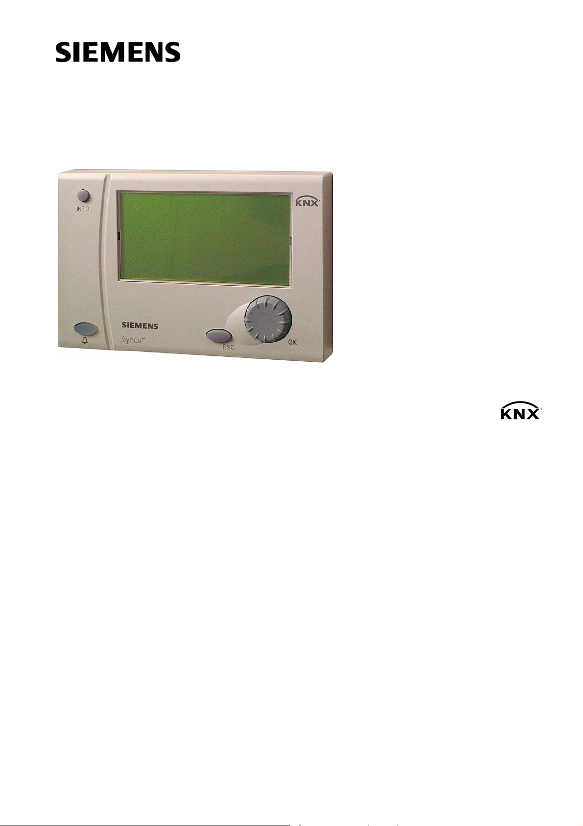
Synco
™
700
Bus Operator Unit RMZ792
Basic Documentation
Edition 1.0
Series A
CE1P3113en
03.04.2006
Building Technologies
HVAC Products
Page 2

Siemens Switzerland Ltd
Building Technologies Group
International Headquarters
HVAC Products
Gubelstrasse 22
CH- 6301 Zug
Tel. +41 41 724 24 24
Fax +41 41 724 35 22
www.sbt.siemens.com
2/52
Building Technologies Bus operator unit RMZ792 CE1P3113en
HVAC Products 03.04.2006
© 2006 Siemens Switzerland Ltd
Subject to alteration
Page 3

Contents
1 Summary.........................................................................................................7
1.1 Bus operator unit RMZ792 ..............................................................................7
1.2 Operator units..................................................................................................7
1.3 Topology of Synco™ 700................................................................................8
1.4 Product documentation....................................................................................8
1.5 Key features ....................................................................................................9
1.6 Important notes..............................................................................................10
2 Operation.......................................................................................................11
2.1 Functions of the bus operator unit.................................................................11
2.2 Operating concept.........................................................................................11
2.3 Operating levels.............................................................................................12
2.4 Menu tree ......................................................................................................13
3 Operation of devices......................................................................................15
3.1 Product range................................................................................................15
3.2 Remote operation and local operation...........................................................15
3.3 Navigating on the device list..........................................................................15
3.4 Quick access with favorites...........................................................................16
3.5 Information describing what is visible............................................................16
3.6 Error handling................................................................................................16
3.7 User-defined text...........................................................................................17
4 Power supply.................................................................................................18
4.1 Power supply via Konnex bus .......................................................................18
4.2 External power supply...................................................................................18
4.3 Power supply via Synco™ controller.............................................................19
4.4 Error handling................................................................................................19
5 Commissioning..............................................................................................20
5.1 Entering the commissioning mode ................................................................20
5.1.1 Entry on first startup ......................................................................................20
5.1.2 Entry from the main menu.............................................................................20
5.2 Leaving the password level...........................................................................20
6 “Commissioning” menu..................................................................................21
6.1 Device address..............................................................................................21
6.1.1 Automatic address search.............................................................................21
6.1.2 Manual assignment of addresses..................................................................21
6.1.3 Address assignment with the ETS.................................................................21
6.1.4 Error handling................................................................................................22
3/52
Building Technologies Bus operator unit RMZ792 CE1P3113en
HVAC Products Contents 03.04.2006
Page 4

6.2 Activating communication..............................................................................22
6.2.1 Submenu “Communication”...........................................................................22
6.3 Device list.......................................................................................................23
6.3.1 Submenu “Create list”....................................................................................24
6.3.2 Submenu “Sort list”........................................................................................24
6.3.3 Submenu “Name devices” .............................................................................25
6.3.4 Submenu “Add devices”.................................................................................26
6.3.5 Submenu “Delete devices”.............................................................................26
6.3.6 Submenu “Delete list” ....................................................................................26
6.3.7 Submenu “Display list”...................................................................................27
6.3.8 Submenu “List information”............................................................................27
6.4 Favorites........................................................................................................27
6.4.1 Submenu “Add datapoints”............................................................................28
6.4.2 Submenu “Name datapoints”.........................................................................29
6.4.3 Submenu “Name favorites”............................................................................29
6.4.4 Submenu “Sort favorites”...............................................................................29
6.4.5 Submenu “Delete datapoints”........................................................................30
6.4.6 Submenu “Delete favorites”...........................................................................30
6.4.7 Submenu “Delete all favorites”.......................................................................31
7 Data backup...................................................................................................32
7.1 Local data backup..........................................................................................32
7.2 Data backup on a second unit ....................................................................... 33
7.3 Error handling ................................................................................................34
8 General settings.............................................................................................35
8.1 Time of day and date.....................................................................................35
8.1.1 Format............................................................................................................35
8.1.2 Setting............................................................................................................35
8.1.3 Error handling ................................................................................................36
8.2 Selecting the language ..................................................................................36
8.3 Selecting the unit of temperature...................................................................37
8.4 Contrast of display on the operator unit.........................................................37
8.5 Display of bus fault status messages.............................................................37
8.6 Text entries....................................................................................................37
8.7 Password.......................................................................................................38
8.8 Device list.......................................................................................................38
8.9 Favorite pages...............................................................................................38
9 Device information.........................................................................................39
10 Faults.............................................................................................................40
10.1 Display of faults..............................................................................................40
4/52
Building Technologies Bus operator unit RMZ792 CE1P3113en
HVAC Products Contents 03.04.2006
Page 5

10.1.1 Device list on the “Main menu”......................................................................41
10.1.2 Menu “Faults current”....................................................................................41
10.1.3 Info page and menu “Fault status message bus”..........................................41
10.2 Faults of non-listed bus users........................................................................41
10.3 Acknowledgement of faults............................................................................42
10.4 Resetting faults..............................................................................................42
10.5 Deleting faults................................................................................................42
11 Memory card..................................................................................................43
11.1 Content of memory card................................................................................43
11.2 Exchanging the memory card........................................................................43
12 Support in the event of errors and faults .......................................................44
12.1 Error code list ................................................................................................44
12.2 Rectification of errors.....................................................................................44
13 Electrical connections....................................................................................46
14 Appendix........................................................................................................47
14.1 Abbreviations used in this document.............................................................47
14.2 Editable text...................................................................................................47
5/52
Building Technologies Bus operator unit RMZ792 CE1P3113en
HVAC Products Contents 03.04.2006
Page 6

6/52
Building Technologies Bus operator unit RMZ792 CE1P3113en
HVAC Products Contents 03.04.2006
Page 7
What is the RMZ792
bus operator unit?
Konnex makes it possible
User-friendly
at all levels
Functions
1 Summary
1.1 Bus operator unit RMZ792
The RMZ792 is a communicating operator unit designed for operating Synco™ 700
devices in a Konnex network. The operator unit is suited both for fixed installation and
mobile use (e.g. for use by the service engineer).
Third-party devices cannot be operated with it.
Thanks to the Konnex bus, the bus operator unit can access all Synco™ controllers
installed in the network.
Whether for endusers, engineering, service or commissioning staff, menu-driven operation in clear-text underlines the system’s user-friendliness at all levels.
The RMZ790 and RMZ791 controller operator units and the RMZ792 bus operator unit
use identical operating elements and are based on the same Synco™ operating philosophy.
• Operation of up to 150 devices
• Suited for use with controllers, room units and central units of the Synco™ 700
product family
• Operation of RXB… and RXL… individual room controllers communicating via Konnex
• Automatic device search run within the line / area
• Access to the user and service levels
• Display and acknowledgement of faults from all bus users
• Freely definable passwords for all access levels
• 20 user-defined favorite pages
• Power supply via Konnex bus or external AC 24 V power supply
• Straightforward upgrading of languages, text catalog and device descriptions by
means of plug-in type memory card
• Fixed installation or mobile use
1.2 Operator units
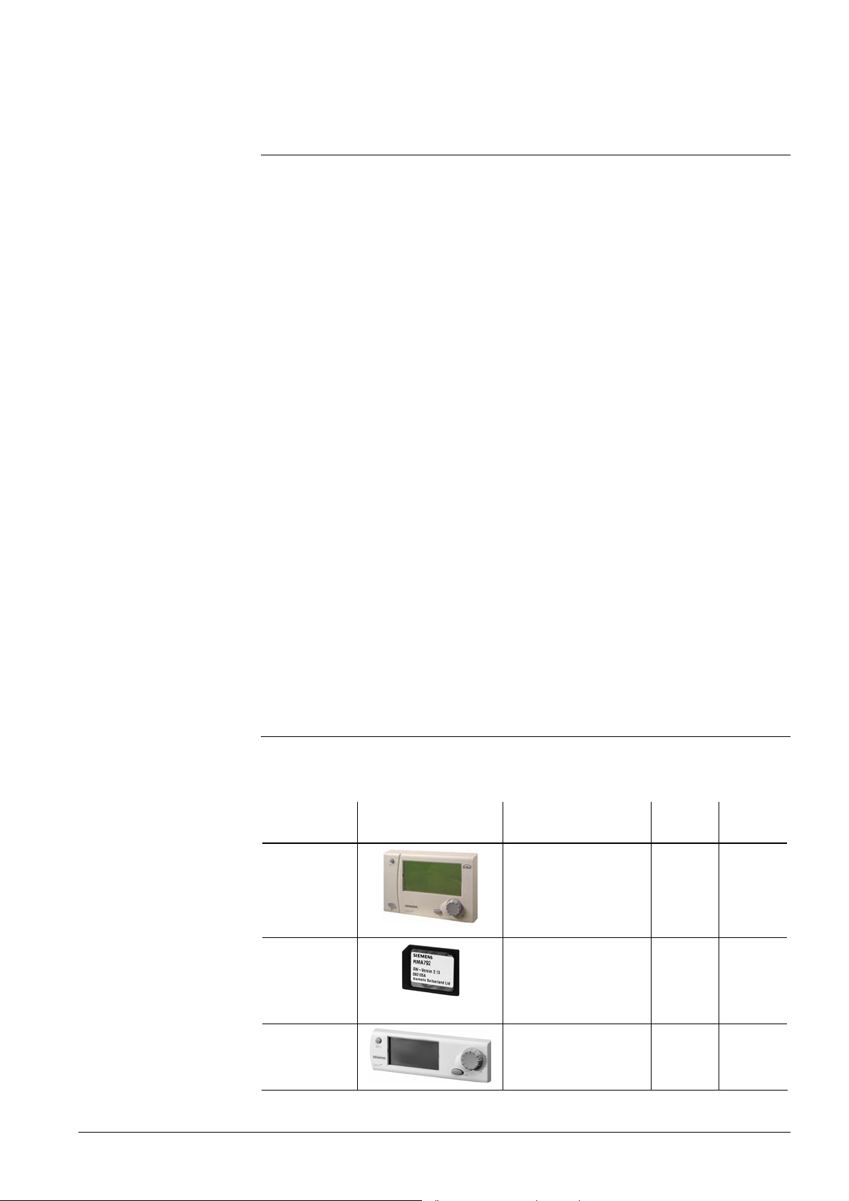
Operator units and
accessories
Synco™ plant can be operated with various types of operator units. They are distinguished by design, the number of devices that can be handled by them, the scope of
functions, the kind of usage and location:
Name Illustration Function
Type
reference
Bus operator
unit
Bus operation for
service staff and
RMZ792
Data
Sheet no.
N3113
users, without commissioning functions
Memory card
for bus operator unit
Operator
unit, plug-in
type
Building Technologies Bus operator unit RMZ792 CE1P3113en
HVAC Products 1 Summary 03.04.2006
Device descriptions
RMA792
N3113
and language catalogs
for the bus operator
unit
Local operation for
RMZ790
N3111
commissioning, service and users
7/52
Page 8
Name Illustration Function
Operator
unit, detached
Local operation for
commissioning, service and users
Type
reference
RMZ791
Data
Sheet no.
N3112
Use of the RMZ792 bus
operator unit
Service and
operator unit
PC software for commissioning, service
OCI700.1
N5655
and users
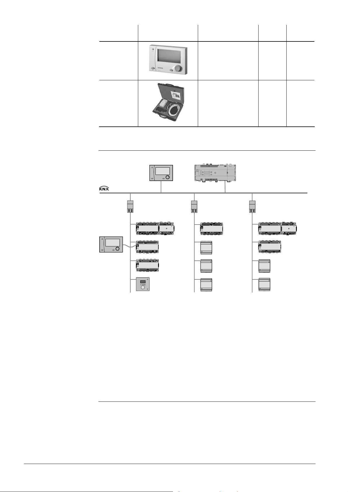
1.3 Topology of Synco™ 700
The illustration below shows a typical topology for using the RMZ792 bus operator unit:
RMZ792
RMZ792
N140/13
Area 1
N140/13 N140/13
RM…
RMB…
OZW77x
Konnex TP1
RM…
RM…
RM…
QAW740
Line 1
RM… Synco™ 700 controllers
RMB… Central control units
RXB2… Individual room controllers
OZW77… Central communication unit
QAW740 Room unit
N140/13 Line / area coupler
RXB2…
RXB2…
RXB2…
Line 2 Line 3
RXB2…
RXB2…
RMB…
3113Z55en
The bus operator unit is used for operating Synco™ devices within a single line or for a
plant consisting of several lines. Synco™ devices in neighboring lines or areas can
always be accessed, independent of the unit’s location. To keep bus loading at the
lowest possible level, it is recommended to install the operator unit within the line or
area of the relevant bus users wherever possible.
1.4 Product documentation
In addition to the present Basic Documentation, the product documents listed below
provide detailed information about the safe and correct deployment and operation of
Synco™ 700 products in building services plant.
8/52
Building Technologies Bus operator unit RMZ792 CE1P3113en
HVAC Products 1 Summary 03.04.2006
Page 9

Note
Type of document Document no.
Data Sheet “Bus Operator Unit RMZ792” N3113
Installation Instructions “Bus Operator Unit RMZ792” G3113
Environmental Declaration “Bus Operator Unit RMZ792” E3113
Product range description “HVAC controllers with Konnex interface” S3110
Basic Documentation “Communication with Konnex bus” P3127
Data Sheet “Konnex bus KNX” N3127
Synco™ 200 / Synco™ 700 Valid Version Set J3100
CE Declaration of Conformity Synco 700 T3110
1.5 Key features
Overview of outfit and functions of the RMZ792 bus operator unit:
Outfit / functions
RMZ792
Operating elements
Select-and-press knob (OK knob)
Info button to display information about the plant
Fault button for optical indication and acknowledgement
Backlit LCD (128×64 picture points)
Operation
Menu-driven operation in clear-text
Access levels
Password protection for each access level
Handling faults
Info page with clear-text display of faults
Visualization of faults with red LED
Display of all faulty devices with fault symbol
Remote acknowledgement and resetting of faults
Display of simultaneous faults (fault list)
Maximum number of bus users
User-defined favorite pages
Number of favorite pages
Number of datapoints per favorite page
Functions
Automatic device search run
Manual adding / removal of devices
Automatic / manual sorting of device list
Naming devices
Adding / removing / naming / sorting favorites
Exchangeable memory card (languages, device information)
Power supply
Konnex bus
Externally, AC 24 V
9
9
9
9
9
3
9
9
9
9
9
20
150
20
10
9
9
9
9
9
9
9
9
The following operating functions cannot be performed from the bus operator unit:
• Access to the datapoints on the password level of the bus users (e.g. commissioning)
• Display of trend graphs
• Deletion of fault history
9/52
Building Technologies Bus operator unit RMZ792 CE1P3113en
HVAC Products 1 Summary 03.04.2006
Page 10
Field of use
Proper use
Electrical installation
Commissioning
Operation
Wiring
Storage and transport
Maintenance
Faults
Disposal
1.6 Important notes
This symbol shall draw your attention to special safety notes and warnings. If such
notes are not observed, personal injury and / or considerable damage to property can
occur.
Synco™ 700 products may only be used for the control and supervision of heating,
ventilation, air conditioning and chilled water plant.
Prerequisites for flawless and safe operation of Synco™ 700 products are proper
transport, installation and commissioning, as well as correct operation.
Fuses, switches, wiring and earthing must be in compliance with local safety regulations for electrical installations.
Preparation for use and commissioning of Synco™ 700 products must be undertaken
by qualified staff who have been appropriately trained by SBT HVAC Products.
Synco™ 700 products may only be operated by staff who have been instructed by SBT
HVAC Products or their delegates and whose attention has been drawn to potential
risks.
When wiring the system, the AC 230 V section must be strictly segregated from the
AC 24 V safety extra low-voltage (SELV) section in order to ensure protection against
electric shock hazard!
For storage and transport, the limits given in the relevant Data Sheets must always be
observed.
If in doubt, contact your supplier or SBT HVAC Products.
Synco™ 700 products are maintenance-free, apart from cleaning at regular intervals.
System sections accommodated in the control panel should be freed from dust and dirt
whenever normal service visits are due.
Should system faults occur and you are not authorized to make diagnostics and to
rectify faults, call your Siemens customer service.
Only authorized staff are permitted to make diagnostics, to rectify faults and to restart
the plant. This also applies to work carried out within the control panel (e.g. safety
checks or replacement of fuses).
The products contain electrical and electronic components and must not be
disposed of as domestic waste.
Local and currently valid legislation must be observed
10/52
Building Technologies Bus operator unit RMZ792 CE1P3113en
HVAC Products 1 Summary 03.04.2006
Page 11
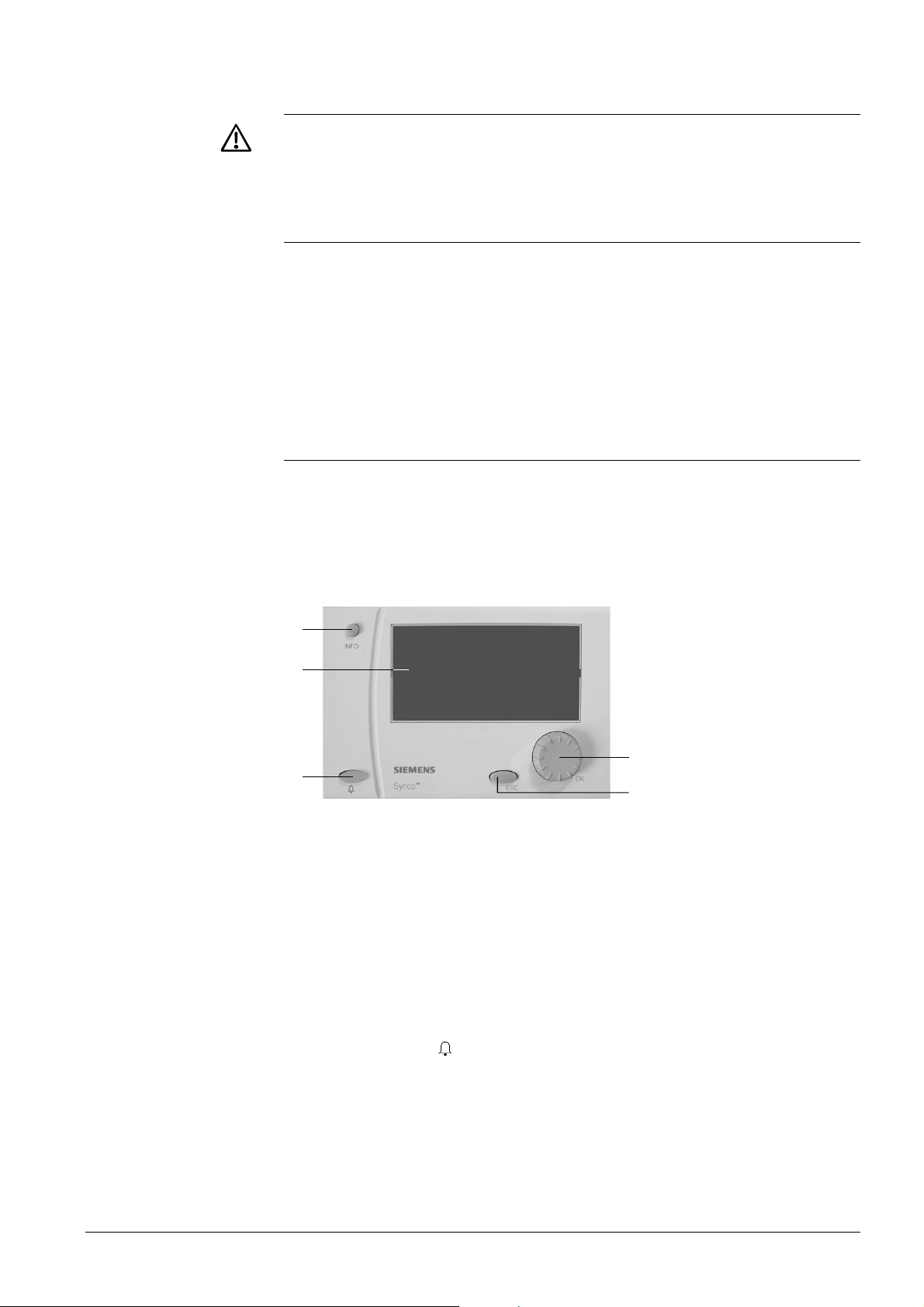
General
Operating elements
2 Operation
Synco™ 700 devices may only be operated by staff who have been instructed by
SBT HVAC Products or their delegates and whose attention has been drawn to
potential risks.
2.1 Functions of the bus operator unit
The RMZ792 bus operator unit is used to make all settings and readouts required for
operating a device. All entries made on the bus operator unit are transmitted to the
respective device where they are handled and stored; the operator unit itself does not
store any data. The information required by the user is generated by the devices and
transmitted to the operator unit for display. The text catalog in different languages and
the description of the operating structure of all operable Synco™ 700 devices are
stored locally on the exchangeable memory card (RMA792) in the operator unit.
2.2 Operating concept
On the software side, all settings and readout values are arranged as datapoints (operating lines) of the menu tree. Using the operating elements, every datapoint can be
selected, displayed or set. All menus appear on the LCD as clear-text.
The bus operator unit has several languages preprogrammed; when commissioning the
plant, the required language must be activated. The Operating Instructions for the user
are integrated in the Installation Instructions (G3113).
2
3112P01
1
3
5
4
1
2
3
4
5
When one of the operating elements is operated, the backlit display will automatically
be switched on. If there is no operation for 30 minutes, it will be switch off again and the
start page appears. In the event of pending faults, the fault information page is displayed in place of the start page.
Display
INFO button
Function 1: Display of key plant data
Function 2: Display of information about the individual datapoints on the
current menu
OK select-and-push knob
Turn: Selection of operating line or readjustment of value
Press: Confirmation of operating line or setting
ESC button
Going back to the previous menu
Canceling readjustment of value
Fault button “
“ with LED
LED: Indication of fault
Press: Acknowledgement of fault or reset
Bus operator unit
RMZ792
11/52
Building Technologies Bus operator unit RMZ792 CE1P3113en
HVAC Products 2 Operation 03.04.2006
Page 12
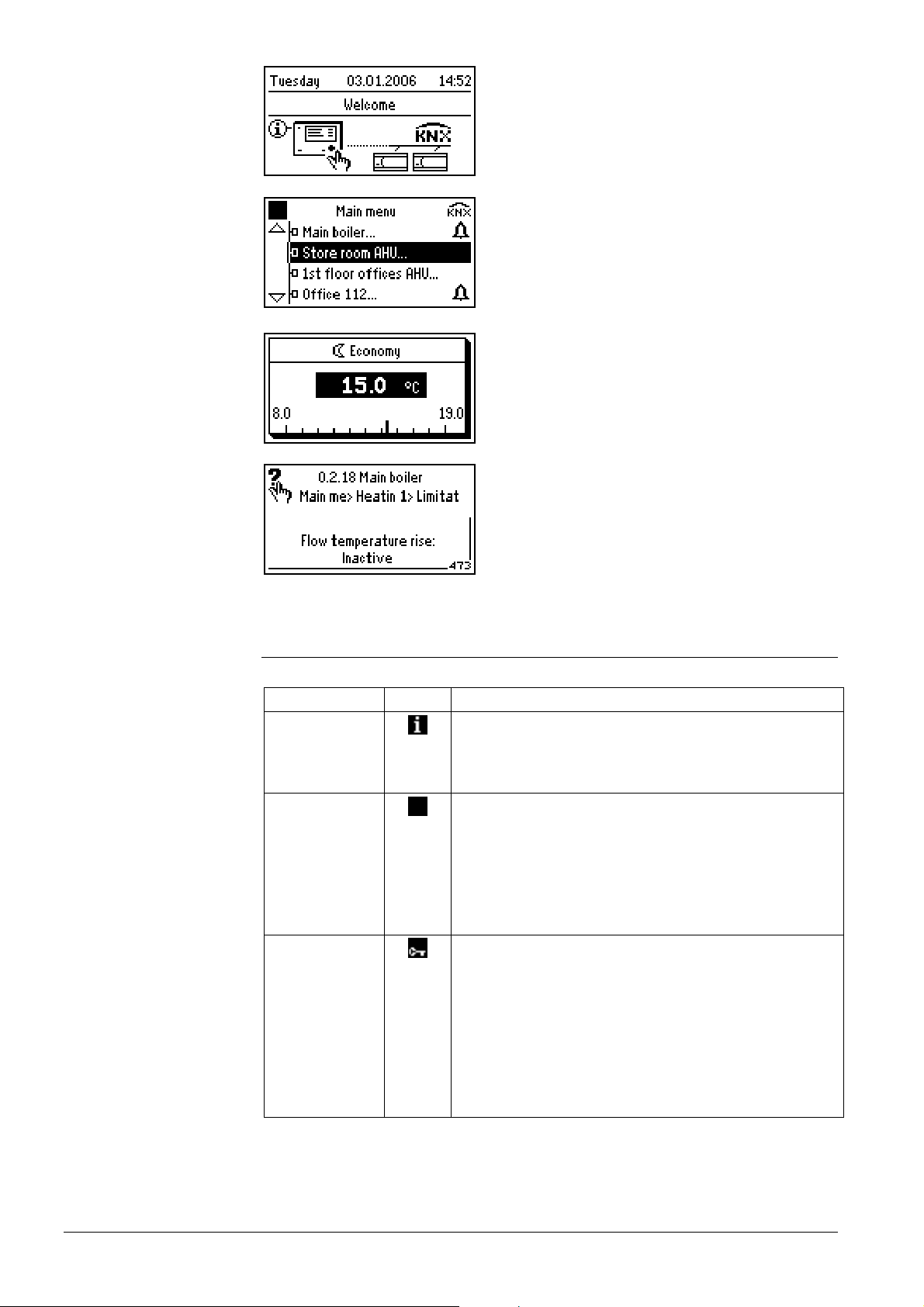
Display examples
Start page
Device list, partly with fault symbol
Pop-up, setting a numerical value
Help picture with explanations relating to the
selected setting parameter
2.3 Operating levels
The following operating levels are available:
Level Icon Description
Info level
On the info level, important plant data (fault and service
information) can be retrieved and displayed. No values
can be changed here. The info level can be accessed at
any time and is not password-protected.
User level
The user level is made up in the form of a menu tree.
Here, datapoints can be read and / or their values
changed. The user level can be protected by a password
to prevent unauthorized access. The bus operator unit is
supplied with no password protection activated.
From this level, the user level of the bus users can be
accessed.
Service level
The Service level provides access to other menus and
datapoints of the bus operator unit. The service level of
the bus operator unit can be protected by a password to
prevent unauthorized access. The unit is supplied with no
password protection activated.
From this level, the service level of the bus users can be
accessed, e.g. for setting parameters or for plant maintenance.
12/52
Building Technologies Bus operator unit RMZ792 CE1P3113en
HVAC Products 2 Operation 03.04.2006
Page 13
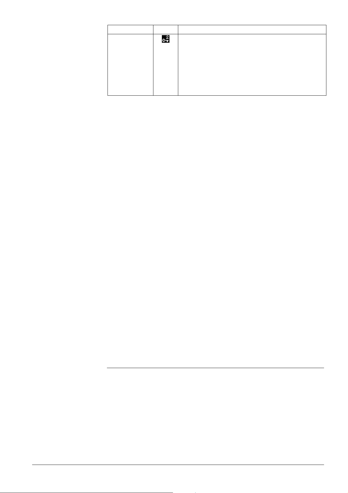
Switching between
operating levels
Level Icon Description
Password level
The password level displays additional menus and datapoints for configuring and commissioning the bus operator unit. The password level is protected by a password to
prevent unauthorized access. The unit comes standard
with number “7” as the password.
From this level, the password level of the bus users
cannot be accessed; the setting only acts locally.
With the exception of the info level, operation is structured in the form of a menu tree.
Individual menus or operating lines are enabled depending on the access level. The
higher access level always displays all menus and operating lines of lower access
levels also; the password level shows the entire menu tree. The active level is indicated
by an appropriate symbol at top left.
Using the INFO button, explanations relating to the menus and the individual datapoints
can be displayed. The information is displayed as long as the button is kept depressed.
Switching to the info level:
1. Press the ESC button repeatedly until the start page reappears.
2. Press the INFO button or turn the OK knob to change to the info level.
3. To navigate within the info pages, press the INFO button repeatedly or turn the OK
knob.
Switching to the user level:
1. Selecting the start page: Press the ESC button repeatedly until the start page
reappears.
2. Press the OK knob.
3. If the user level is password-protected, the Access levels menu appears now.
4. Select the User level by turning the OK knob.
5. Enter the password required for the respective access level.
6. Press the OK knob to confirm the password.
Switching to the service level or password level:
1. Selecting the start page: Press the button repeatedly until the start page reappears.
2. Press the OK knob and the ESC button simultaneously. The Access levels menu
appears.
3. Select the required access level by turning the OK knob and confirm by pressing
the knob.
4. If necessary, enter the password required for the respective access level.
5. Press the OK knob to confirm the password.
If there is no operating action for 30 minutes, the unit will automatically change to the
start page and the user level.
2.4 Menu tree
The menu tree of the bus operator unit is divided into 3 types of menus:
1. Info:
Values cannot be changed. The pages are on the info level and cannot be protected by a password.
2. Devices:
Device list with all bus users. The menu tree of the respective bus user can be
opened via the user’s device name.
Alternatively, the most important and most frequently used datapoints of bus users
can be accessed via user-defined favorite menus.
13/52
Building Technologies Bus operator unit RMZ792 CE1P3113en
HVAC Products 2 Operation 03.04.2006
Page 14
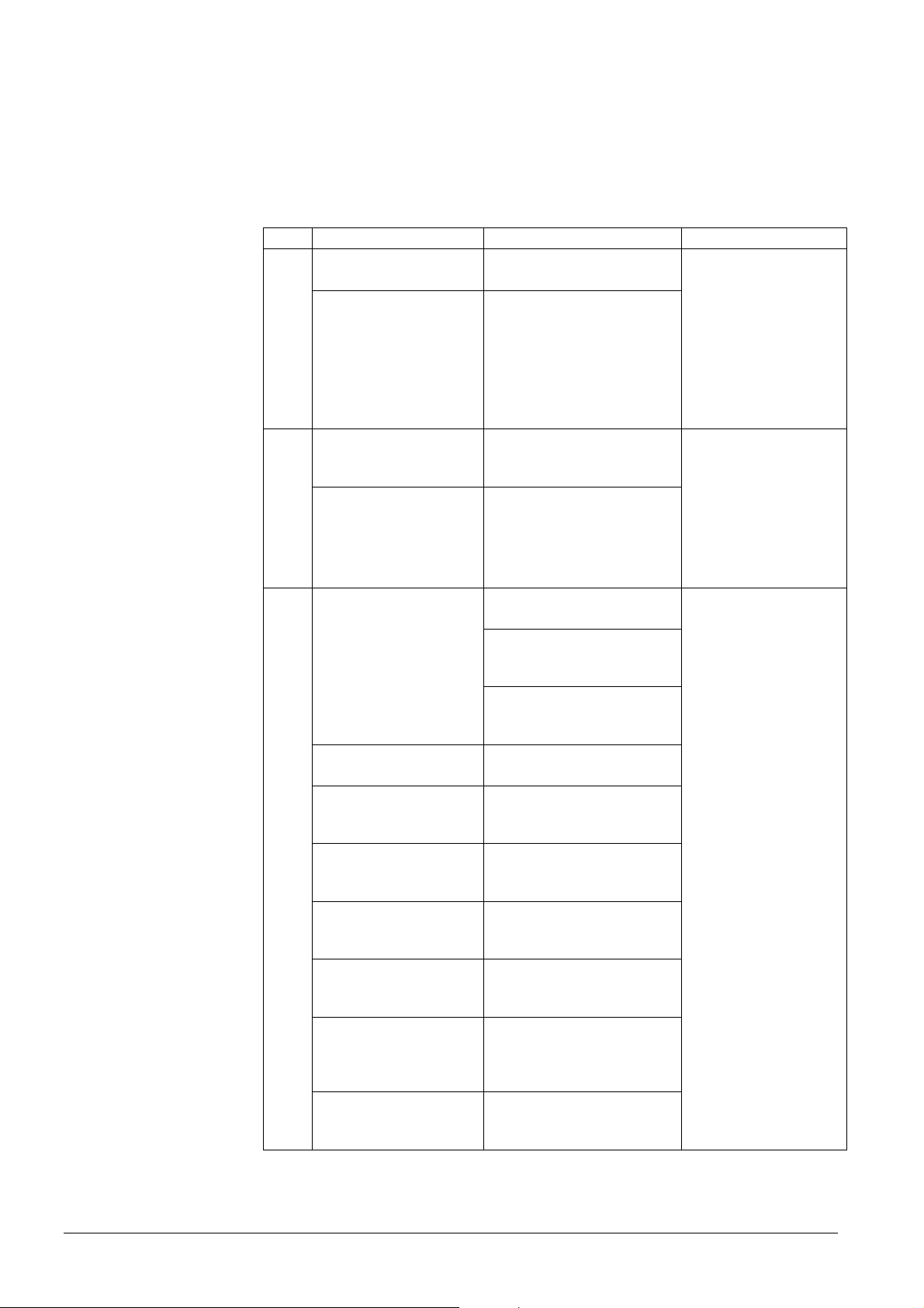
The datapoints can be displayed or changed. Optionally, the menus can be protected by a password (user level) to prevent unauthorized access.
3. Local menus:
All settings of the bus operator unit are made on the local menus. The settings are
not valid for bus users on the device list. The menus appear in accordance with the
operating level currently used and are protected by the passwords of the service
and password levels.
Type Menu name Functions Range of action
Fault status signal
bus…
Service information… Business card
1. Info
Plant operating state
Read access only
No password protec-
tion
Favorites…
Device name 1
Device name 2
…
2. Devices
Device name(s) …
Commissioning…
Device list…
Favorite pages…
Time of day / date…
Faults…
3. Local menus
Settings…
Device information…
Data backup…
User-definable menus with
the most important values
Device list:
Access to devices 1…n
Settings for communication
Makeup and format of
device list
Makeup and contents of
favorite pages
Presentation of device list
Presentation of favorite
pages
Settings of time of day and
date
Display of current faults
and of faults on the bus
Settings, such as language,
passwords and texts
Device information, such as
hardware and software
versions
Storing and retrieving
settings
Synco bus users
Read and write ac-
cess
Password protection
(optional)
RMZ792 local
Partly with password
protection
14/52
Building Technologies Bus operator unit RMZ792 CE1P3113en
HVAC Products 2 Operation 03.04.2006
Page 15
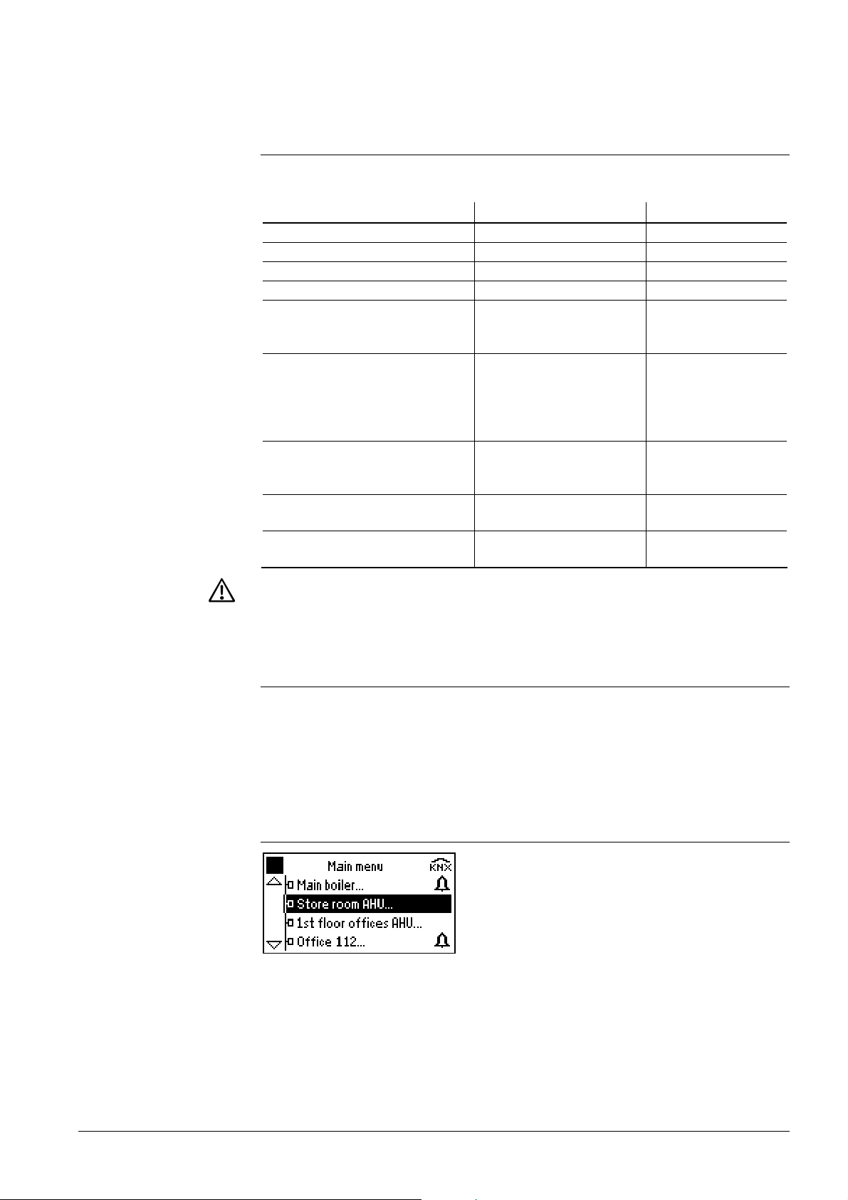
3 Operation of devices
3.1 Product range
The RMZ792 bus operator unit is used for operating the following devices of the
Synco™ family (situation February 2006):
Type of unit Type reference Data Sheet no.
Central control unit RMB795… N3121
Heating controllers RMH760… N3131 and N3133
Boiler sequence controller RMK770… N3132
Switching and monitoring device RMS705… N3123
Universal controllers RMU710…
RMU720…
RMU730…
Room controllers RXB… RXB21.1/FC-09
RXB21.1/FC-10
RXB21.1/FC-11
RXB22.1/FC-08
RXB22.1/FC-12
Room controllers RXL… RXL21.1/FC-10
RXL21.1/FC-11
RXL22.1/FC-12
Room unit for
QAW740 N1633
Synco™ 700 controller
Central communication units OZW771…
OZW775…
To ensure trouble-free functioning of the bus operator unit, compatible software versions
of the different types of communicating units must be combined. For compatible units and
versions, refer to document J3100 (Synco™ 200 / Synco™ 700 Valid Version Set).
N3144
N3144
N3144
N3872
N3873
N3873
N3872
N3873
N3877
N3877
N3877
N3117
N5663
3.2 Remote operation and local operation
The bus operator unit provides access to the datapoints of the bus users’ user
and service levels. But the datapoints of the bus users’ password level are to be
accessed via the local RMZ790 and RMZ791 operator units. For this reason, the
RMZ792 bus operator unit cannot be used for configuring and commissioning
plant.
3.3 Navigating on the device list
During commissioning, the device list (list containing all bus users) is generated. Datapoints are always to be accessed via the device list – with the exception of the favorite
pages (refer to section 3.4 “Quick access with favorites”). By selecting the required unit
from the device list, the operator reaches the menu tree of the unit needed.
Menu tree and navigation are not any different from local operation with the
RMZ790 or RMZ791.
When pressing the INFO button during navigation, the following information is displayed:
15/52
Building Technologies Bus operator unit RMZ792 CE1P3113en
HVAC Products 3 Operation of devices 03.04.2006
Page 16
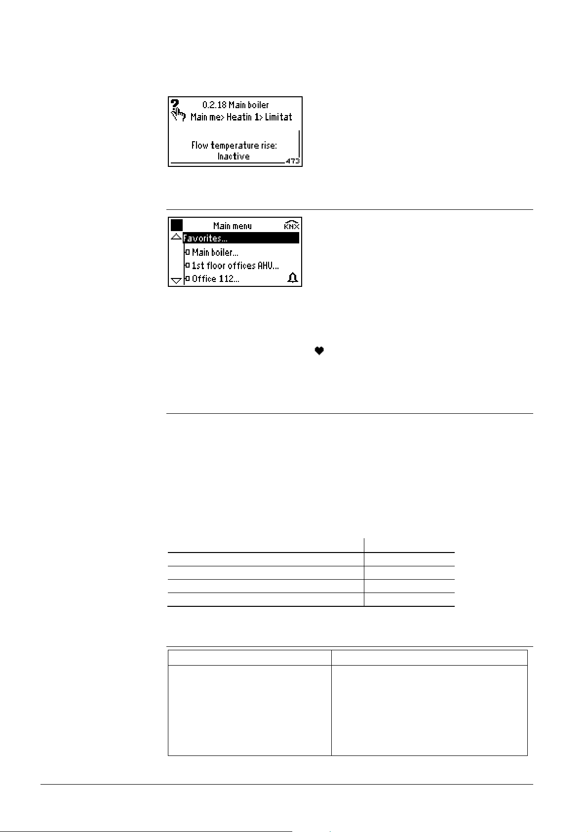
• The device name and – if appropriately set – the device address
• The current position in the menu tree (path)
• Long text relating to the selected datapoint
The information is displayed as long as the button is kept depressed.
3.4 Quick access with favorites
The favorite pages provide a user interface matched to the requirements of every day
use. On the favorite pages, simple datapoints of any devices from the device list can be
combined. From their location in the menu tree of the respective device, the datapoints
are copied to the required favorite page. This makes navigation much more efficient. All
favorite pages are identified by the
symbol in the corner at top right. This makes it
easy to distinguish between favorite pages and the unit’s menu tree.
3.5 Information describing what is visible
Certain Synco devices deliver information that describes what is visible. When using
this information, the user interface only displays datapoints that are important for the
controller’s current configuration.
If a device does not support this kind of information, the bus operator unit will display all
available datapoints – independent of the device’s configuration. For this reason, datapoints may assume values that do not make sense and setting values may not trigger
any actions because the device’s current configuration does not support them or they
are inactive.
The following types of devices do not contain information describing what is visible:
Type of device Type reference
Room controller RXB…, RXL…
Central communication unit OZW771…
Central communication unit OZW775…
Room unit for Synco™ 700 controller QAW740
3.6 Error handling
Possible cases
Error / error message Cause / remedy
Caution!
Device version not supported
• The device description version of the bus
operator unit and the software version of
the target device do not match
• Find compatible versions of memory card
and device (VVS)
• Exchange the memory card (RMA792) of
the bus operator unit or the target device
16/52
Building Technologies Bus operator unit RMZ792 CE1P3113en
HVAC Products 3 Operation of devices 03.04.2006
Page 17

Error / error message Cause / remedy
Caution!
Device not responding
• Communication with target device is not
possible
• Is the device in operation?
• Is the device connected to the Konnex
bus?
• Has the device address been changed?
Datapoint shows a value that does
not make sense (e.g. room temperature 655.3 °C)
The device does not support information
describing what is visible; datapoint has no
meaning in the current configuration
Setting does not produce any effect The device does not support information
describing what is visible; datapoint has no
meaning in the current configuration
3.7 User-defined text
User-defined text from the devices is adopted, which means that the display on the bus
operator unit is identical with that on the local operator unit (RMZ790 / RMZ791). The
bus operator unit reads the user-defined text from the respective device. The RMZ792
displays the default text until the text from the device is received.
17/52
Building Technologies Bus operator unit RMZ792 CE1P3113en
HVAC Products 3 Operation of devices 03.04.2006
Page 18
Notes
4 Power supply
The bus operator unit can be powered in 3 different ways:
• Via Konnex bus (45 mA)
• Via an external power source (AC 24 V)
• Via the service interface of a Synco™ controller (not recommended)
• When using the cable supplied with the bus operator unit, plug correctly the RJ45
connector into the appropriate socket of the RMZ792 (audible click)
• Move the KNX / EXT slide switch for selecting the type of power supply to its end
position
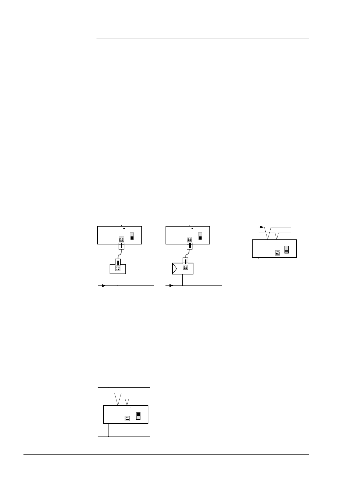
4.1 Power supply via Konnex bus
• If the bus operator unit is used in a location where AC 24 V power supply is not
available (mobile use, installation in some other space), the unit can be powered via
the Konnex bus
• Power supply must be such that 45 mA are available for the bus operator unit. This
necessitates at least 2 active decentral bus power supplies via Synco™ controllers
or 1 central bus power supply
• The slide switch at the rear of the bus operator unit must be set to KNX
• Using the cable supplied with the unit, the RMZ792 is to be connected to a Konnex
bus socket (figure a) or a Synco™ controller (figure b)
• The Konnex bus cable is to be connected to terminals CE+ and CE– on the base
(figure c; observe polarity)
a)
G0
CE
CE+
G
KNX
S
KNX
S1
b) c)
CE
CE+
G
G0
KNX
S
3113A05
KNX
S1
45 mA
G0
KNX
CE
CE+
G
KNX
S
KNX
S1
3113A07
45 mA
Synco RM...
N1
KNX TP1
X1
45 mA
KNX Konnex bus
N1 Synco™ 700 controller
S1 Bus operator unit RMZ792
X1 Bus socket
4.2 External power supply
KNX TP1
• External AC 24 V power supply is recommended in the case of fixed installations
(e.g. in the control panel door). This means that the decentral / central bus power
supply does not have to carry the load of the bus operator unit and can be used for
powering other bus users
• The slide switch at the rear of the bus operator unit must be set to EXT
• AC 24 V is supplied to the bus operator unit via terminals G and G0
SP
KNX
CE
CE+
SN
AC 24 V
G
G0
KNX
S
EXT
3113A02
18/52
Building Technologies Bus operator unit RMZ792 CE1P3113en
HVAC Products 4 Power supply 03.04.2006
Page 19
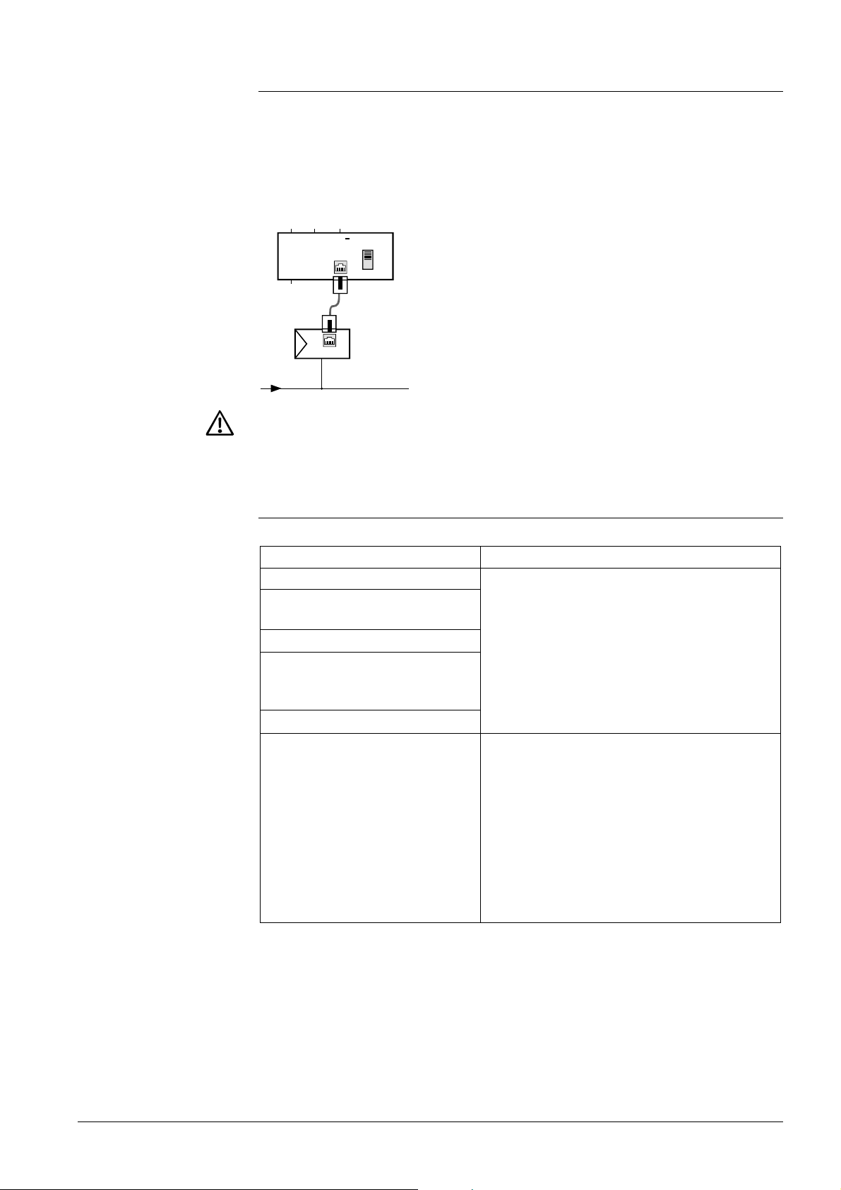
4.3 Power supply via Synco™ controller
• In exceptional cases, the bus operator unit can also be powered via the service
interface of a Synco™ controller. Because of the additional power consumption of
the bus operator unit, this type of power supply is possible only if the controller is
equipped with no more than 3 extension modules
• The slide switch at the rear of the bus operator unit must be set to EXT
• The bus operator unit is to be connected to the service interface of the Synco™
controller using the cable supplied with the unit
CE
CE+
G0
G
KNX
S
3113A06
EXT
S1
Synco RM...
45 mA
N1
KNX TP1
If the bus operator unit is connected while the controller is in operation, the extension
modules might deliver fault status messages. The faults may lead to short-time interruptions of plant operation. The fault status messages must be acknowledged and reset.
4.4 Error handling
Possible cases are:
Error Cause / remedy
Bus operator unit does not start
Bus operator unit is cyclically
restarted
Konnex bus is locked
Operating values of the bus users
are not correctly displayed or
cannot be changed
Backlit display very faint
Controller indicates failure of
extension modules, parts of the
plant fail
• Wrong polarity CE+ / CE–
• Wrong polarity G / G0
• Insufficient power supply via Konnex bus
(undersized bus power supply, too low bus
voltage)
• Wrong slide switch position (KNX / EXT) or
switch in an inadmissible intermediate position
• RJ45 connector not correctly plugged in (no
contact)
The slide switch is in the EXT position and the
bus operator unit was connected while the
controller was in operation.
Remedy:
1. Acknowledge the fault status messages and
reset them.
2. Connect the bus operator unit to a controller
with no extension modules or switch on the
controller only after the bus operator unit
has been connected.
19/52
Building Technologies Bus operator unit RMZ792 CE1P3113en
HVAC Products 4 Power supply 03.04.2006
Page 20
5 Commissioning
Preparation for use and commissioning of Synco™ 700 devices must be undertaken by qualified staff who have been appropriately trained by SBT HVAC Products or their delegates.
5.1 Entering the commissioning mode
5.1.1 Entry on first startup
When supplying power to the bus operator for the first time, the Language menu appears. Here, the language required for operating the plant can be selected. Then, the
Commissioning menu will appear.
The access level is set to “Password level”.
The bus operator unit is to be commissioned in accordance with the Installation Instructions G3113; they are enclosed with the RMZ792.
5.1.2 Entry from the main menu
The Commissioning menu is reached after selecting operating line Commissioning (appears only on the password level) and confirmation with the OK knob.
5.2 Leaving the password level
On completion of commissioning, select the user level (access level for the plant operator). To do this, proceed as follows:
1. Select the start page: Press the ESC button repeatedly until the start page reappears.
2. Press the OK knob and the ESC button simultaneously. The Access levels menu
appears.
3. Press the OK knob.
4. Select the User level by turning the OK button and confirm by pressing the knob.
5. If required, enter the password needed for the user level.
6. Press the OK knob to confirm the password.
20/52
Building Technologies Bus operator unit RMZ792 CE1P3113en
HVAC Products 5 Commissioning 03.04.2006
Page 21

Important!
6 “Commissioning” menu
• Prerequisite for trouble-free operation of the bus operator unit is correct assignment
of the device addresses of all bus users including the line couplers
• The device addresses of all bus users and line couplers must accord with their
positions in the network topology (area.line.address). Wrong device addresses can
lead to unexpected responses and results when commissioning the bus operator unit
6.1 Device address
Like all other bus users, the bus operator unit must have an unambiguous device address. The device address can be set in 3 different ways. Depending on usage, one or
the other method is the more suited. The RMZ792 is supplied with the device address
set to 0.2.255 (area.line.address).
With device address 255, Synco™ devices do not send any process data. Device
addresses 253 and 254 are reserved for special devices.
6.1.1 Automatic address search
• Automatic address search is recommended in situations where the bus operator unit
is subsequently fitted to an existing plant without having knowledge of the existing
address assignment
• At the request of the operator, the bus operator unit looks for the subnetwork address (SNA, consisting of area and line) in the superposed line coupler. If no subnetwork address is received, the last setting of area and line will be used
• Now, starting at 252, the bus operator unit searches for a free device address within
the line. If the address is already used, a new automatic search attempt is made using an address whose value is reduced by 1. The search continues until a free device address is found. The device address is set to 255 if no free device address can
be found
6.1.2 Manual assignment of addresses
• Manual assignment of addresses is recommended in situations where the bus operator unit has a firm place in the network and the address from a network plan has
already been defined and is known
• Area, Line and Device address are manually predefined by the operator
• If the area or the line is changed, the bus operator unit looks for the subnetwork
address (SNA, consisting of area and line) in the superposed line coupler. When the
line coupler delivers an SNA, the device adopts the line coupler’s SNA and overwrites any deviating manual settings. If no SNA is received, the set value of Area or
Line will be adopted
• If the required device address is already used by some other device, the setting
value will be reset to the previous value
6.1.3 Address assignment with the ETS
• This programming mode is used when addresses in the Konnex network are assigned with the ETS
• Area, line and device address are predefined in the ETS
• Set the Programming mode on the bus operator unit to On
• Use the ETS to load the respective device address
• After the bus operator unit has received the address, the Programming mode will
automatically change to Off
21/52
Building Technologies Bus operator unit RMZ792 CE1P3113en
HVAC Products 6 “Commissioning” menu 03.04.2006
Page 22
Possible cases
6.1.4 Error handling
Error Cause / remedy
No communication with other bus users The device address is 255, which means
that communication is not active.
Set the device address to a value between 1 and 252 (automatic search or
manual predefinition).
The subnetwork address (area or line) of
the line couplers and / or the bus users do
not correspond.
Check the subnetwork addresses or
The subnetwork address (SNA) has not
been adopted by the superposed line
coupler
reassign them.
There is no superposed line coupler, or
the line coupler is configured in a way that
it does not send the SNA to the line.
Configure the line coupler accordingly or
predefine the SNA manually.
Fault status message
6001 >1 identical bus address
There are several bus users with identical
device addresses on the network. Correct
the device addresses on the respective
devices accordingly.
General
Operating lines
Notes
6.2 Activating communication
Communication is activated when:
• The device has a valid device address
• Bus power supply is available
• The device is not on the commissioning menu
6.2.1 Submenu “Communication”
A detailed description of communication is given in Basic Documentation P3127 “Communication via Konnex bus”. Basic knowledge of device addresses and network topologies is a prerequisite here.
Main menu > Commissioning > Communication
Operating line Range Factory setting
Area 0…15 0
Line 0…15 2
Device address 1…255 255
Search address --- / Address found --Programming mode Off / On Off
Setting values Area, Line and Device address are used to manually create individual
device addresses.
Automatic address search is triggered via operating line Search address. A successful
address search is acknowledged with status Address found. Status Address failed indicates that the address search has been unsuccessful.
For assigning addresses via the ETS, the programming mode must be set to On. After
successful address assignment, the ETS will automatically switch the value back to Off.
• If a line coupler superposed in the network topology delivers SNA information other
than the values set for the area and the line, the line coupler’s values will be adopted
• If 2 devices have identical device addresses, an error message will be delivered
22/52
Building Technologies Bus operator unit RMZ792 CE1P3113en
HVAC Products 6 “Commissioning” menu 03.04.2006
Page 23
Definition
Presentation
6.3 Device list
The device list is the list containing the bus u sers that c an be op erated. The system
switches from the device list of the bus operator uni t to the menu tree of the bus user. Bus
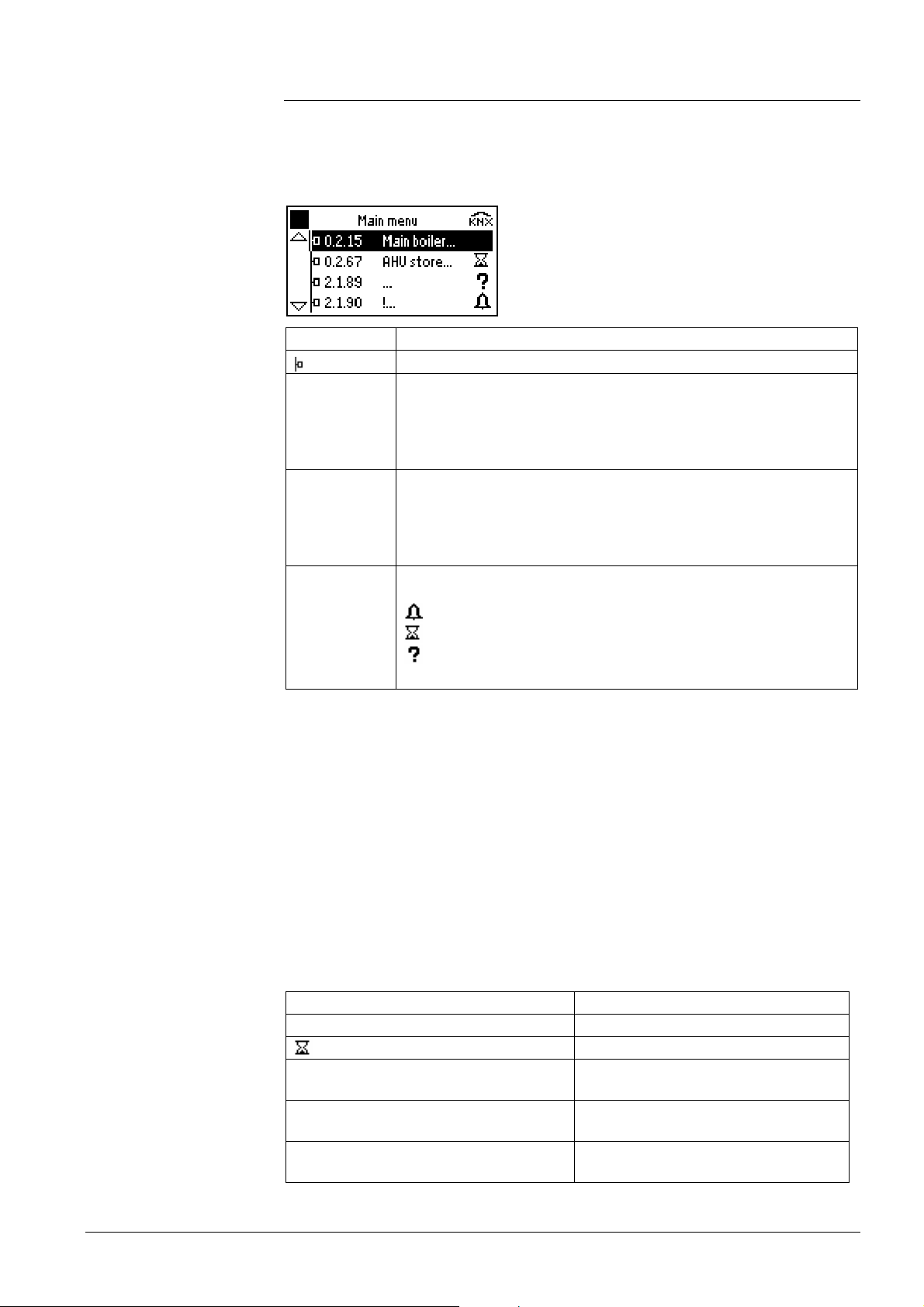
users that do not appear on the device list cannot be opera ted via t he bus ope rator unit .
Bus users are presented on the device list as follows:
Functions
Information Description
A.L.A
Symbol for bus user
Konnex device address (optional):
B : Area [0…15]
L : Line [0…15]
A : Address [1…255]
Also refer to subsection 6.3.7 “Submenu “Display list””
Name
Device name:
Main boiler : Text, max. 20 characters (“Main boiler” is an example!)
… : Device without name
!… : Name of device cannot be read
Also refer to subsection 6.3.3 “Submenu “Name devices””
State
Device state:
: Device in order, no fault pending
: Device indicating a fault
: State read by the device
: State cannot be read, potential failure
Also refer to subsection 10.1.1 “Device list on the “Main menu””
A number of functions make it possible to generate a device list matched to the individual requirements of the user:
• Automatic search for Synco™ devices within a line or area
• Adding Synco™ devices later:
− Individual devices
− All devices within an line
− All devices within an area
• Removing individual devices from the device list
• Naming and renaming device names on the device list
• Selecting presentation of the devices on the device list
• Changing the order of the devices on the device list
• Deleting the entire device list
In connection with the device list operations, the following status messages are displayed, depending on the menu:
Status messages Description
---
Searched for
Command has not yet been executed
Command is being executed
Device list has been successfully
created
Added
Devices have been successfully added
to the list
Address invalid
Device searched for does not exist or
does not reply
23/52
Building Technologies Bus operator unit RMZ792 CE1P3113en
HVAC Products 6 “Commissioning” menu 03.04.2006
Page 24
Use
Operating lines
Status messages Description
Sorted
Device list has been successfully
sorted
Deleted
Device list has been successfully
deleted
Sorted
Device search not possible with the
current settings of area and line
6.3.1 Submenu “Create list”
• When the bus operator unit is connected to plant for the first time
• When the bus operator unit is connected to plant as a service unit
Main menu > Commissioning > Device list > Create list
Operating line Range Factory setting
Area 0…15 0
Line * / 0…15 2
Start search --- / Searched for --Number of devices current 0…150 0
A search is made in the network for operable Synco™ devices in accordance with the
parameters set. An existing device list will first be deleted. The search for devices is
only possible within the selected area. Settings Area and Line confine the search for bus
users to the required part of the network. This also reduces the time required for the
search to a reasonable level.
When using setting “
*” for the line, the search covers all lines of the required area. In
that case, the search lasts about 15 minutes and cannot be aborted.
The device search is started via operating line Start search.
The number of devices found is displayed by the value of Number of devices current.
Caution
Notes
Use
When creating the device list, all existing devices, device names and favorite
pages will be deleted!
• The device list can comprise a maximum of 150 devices. If a network contains more
than 150 bus users, the search will be stopped after 150 devices. On the List informa-
tion menu, a List error is shown as List complete
• In the case of plant with several bus operator units, only one of them can make a
search run at a time
• A device search across all lines (Line =
*) is only possible in the bus operator unit’s
own area
• Settings Area and Line must not be changed during the device search run.
• If a power failure occurs during a search run, or if the bus operator unit is removed
during a search run, the device list will be declared List invalid
• Commands are ignored as long as a device search run is in progress
• When creating the device list, the local names of the devices will be adopted by the
list. If, subsequently, the name is changed locally on the controller, the device list will
not automatically be updated
6.3.2 Submenu “Sort list”
• Sorting the device list in ascending device address order
• Sorting the device list in ascending device name order
• Sorting manually with the aim to have frequently operated devices at the beginning
of the list
24/52
Building Technologies Bus operator unit RMZ792 CE1P3113en
HVAC Products 6 “Commissioning” menu 03.04.2006
Page 25
Operating lines
Operating lines
Main menu > Commissioning > Device list > Sort list
Operating line Range Factory setting
Sort automatically by Device addresses /
---
Device names
Sort manually
The device list can be sorted either manually or automatically according to predefined
criteria. The sorting process is started via operating line Sort automatically and can be
performed by Device address or Device name.
The device list can be manually sorted on the following submenu.
Main menu > Commissioning > Device list > Sort list > Sort manually
Operating line Range Factory setting
Device address name 1
…
Device address name n 1…150
1…150
After selection of a device, its current position on the device list is displayed. By adjusting the value, the respective device can be shifted to the required position. The position
of each device on the device list can be freely selected (1 = beginning of list, 150 = end
of list). The positions of the other devices will then automatically be changed; the list
does not permit any gaps. If the required position lies behind the current end of the list,
the device will be placed in the last position.
Use
Operating lines
6.3.3 Submenu “Name devices”
Assignment of easy-to-understand and self-explanatory names to the devices.
Main menu > Commissioning > Device list > Name devices
Operating line Range Factory setting
Device address name 1
…
Device address name n Max. 20 characters
Max. 20 characters
The devices on the device list can be assigned a freely selectable name. When creating the device list and when adding devices, the local device name – if available – will
be adopted by the device list. The name of the selected device can be overwritten. The
name change only affects the device list on the bus operator unit; the local name of the
device will be maintained. A device name can comprise a maximum of 20 characters.
A device name also appears on the bus operator unit:
• As the title of the main menu of a bus user
• For orientation purposes if, during navigation in a device’s menu tree, the INFO
button is pressed
• On the menu and info pages for fault indication
25/52
Building Technologies Bus operator unit RMZ792 CE1P3113en
HVAC Products 6 “Commissioning” menu 03.04.2006
Page 26
Use
Operating lines
Note
6.3.4 Submenu “Add devices”
• Adding an individual device to the device list
• Adding devices from some other area to the device list
• Adding devices from some other line to the device list
• Updating the device list
Main menu > Commissioning > Device list > Add devices
Operating line Range Factory setting
Area 0…15 0
Line * / 0…15 2
Device address * / 1…255 *
Start add on --- / Added --Number of devices current 0…150
A search for operable Synco™ devices is made in the network according to the parameters set. The devices found are added to the existing device list. Devices already contained on the device list will not be added again. Settings Area, Line and Device address
confine the search for operable devices to the required part of the network, or even to
an individual device. This also reduces the search time to a reasonable level.
• When using setting
* for the line, the search for devices runs through all the lines of
the required area
• When using setting
* for the device address, the search is started for all devices
within the line
The function is started via operating line Start add on.
The number of devices found is displayed by the value of Number of devices current.
Same notes as in section 6.3.1 “Submenu “Create list”” apply.
Use
Operating lines
Use
Operating line
6.3.5 Submenu “Delete devices”
• Reduction of the device list to the devices most important to the user
• Exclusion of individual devices from operation
Main menu > Commissioning > Device list > Delete devices
Operating line Range Factory setting
Device address name 1
…
Device address name n
After a security check is made, the selected device will be removed from the device list.
The gap on the device list will be closed. Any datapoints of the deleted device will be
removed from the favorite pages.
6.3.6 Submenu “Delete list”
Deleting the entire device list.
Main menu > Commissioning > Device list > Delete list
Operating line Range Factory setting
Delete list --- / Deleted ---
After a security check is made, the entire device list inclusive of device names will be
deleted. In addition, all favorite pages will be deleted.
26/52
Building Technologies Bus operator unit RMZ792 CE1P3113en
HVAC Products 6 “Commissioning” menu 03.04.2006
Page 27
Use
Operating lines
Use
Operating lines
6.3.7 Submenu “Display list”
• Changing the display format of the device list
• Showing the device address on the device list or hiding it
Main menu> Commissioning > Device list > Display list
Operating line Range Factory setting
Type of display Address and name /
Name only
Address and
name
Depending on the selection made, the devices appear on the device list with their
addresses and names, or only with their names.
6.3.8 Submenu “List information”
Displaying detailed information about the current state of the device list.
Main menu > Commissioning > Device list > List information
Operating line Range Factory setting
State of list See below
List error See below
Number of devices current 0…150
State of list and list errors have the following meaning:
State of list Description
Address invalid Device search has been aborted; device list
is invalid and must be recreated
Deleted Device list is empty
Acquired Device list has been created or devices
have been added
List error Description
--- No error; device list is ok
Address twice Device list contains several devices with
identical device addresses. Address conflict
must be eliminated
List complete List is full (150 entries)
The current number of devices on the device list is displayed by the value of Number of
devices current.
6.4 Favorites
Definition
Favorite pages enable the user to quickly access important and frequently used plant
values. A total of 20 pages is available, each with a maximum of 10 datapoints. The
user can freely assign any datapoints of devices on the device list. Favorite pages and
operating lines not used are not displayed in the view of favorites. All favorite pages
show the
symbol in the corner at top right.
All datapoints of the favorite pages can be accessed from the user level, also in the
case where the datapoint in the bus user’s menu tree only appears on the service level.
Functions
A number of functions make it possible to match the favorite pages to individual operator needs:
27/52
Building Technologies Bus operator unit RMZ792 CE1P3113en
HVAC Products 6 “Commissioning” menu 03.04.2006
Page 28
Notes
Use
Operating lines
• Adding favorite pages and datapoints
• Naming the favorite pages (titles)
• Renaming the names of the datapoints
• Sorting the favorite pages
• Deleting datapoints and entire favorite pages
• To improve readability, it is recommended to give the favorite pages self-explanatory
names
• If individual devices are removed from the device list, the associated datapoints on
the favorite pages will also be removed
• When deleting the entire device list, all favorite pages will be deleted also
6.4.1 Submenu “Add datapoints”
• Creating favorite pages
• Complementing favorite pages
• Overwriting existing datapoints
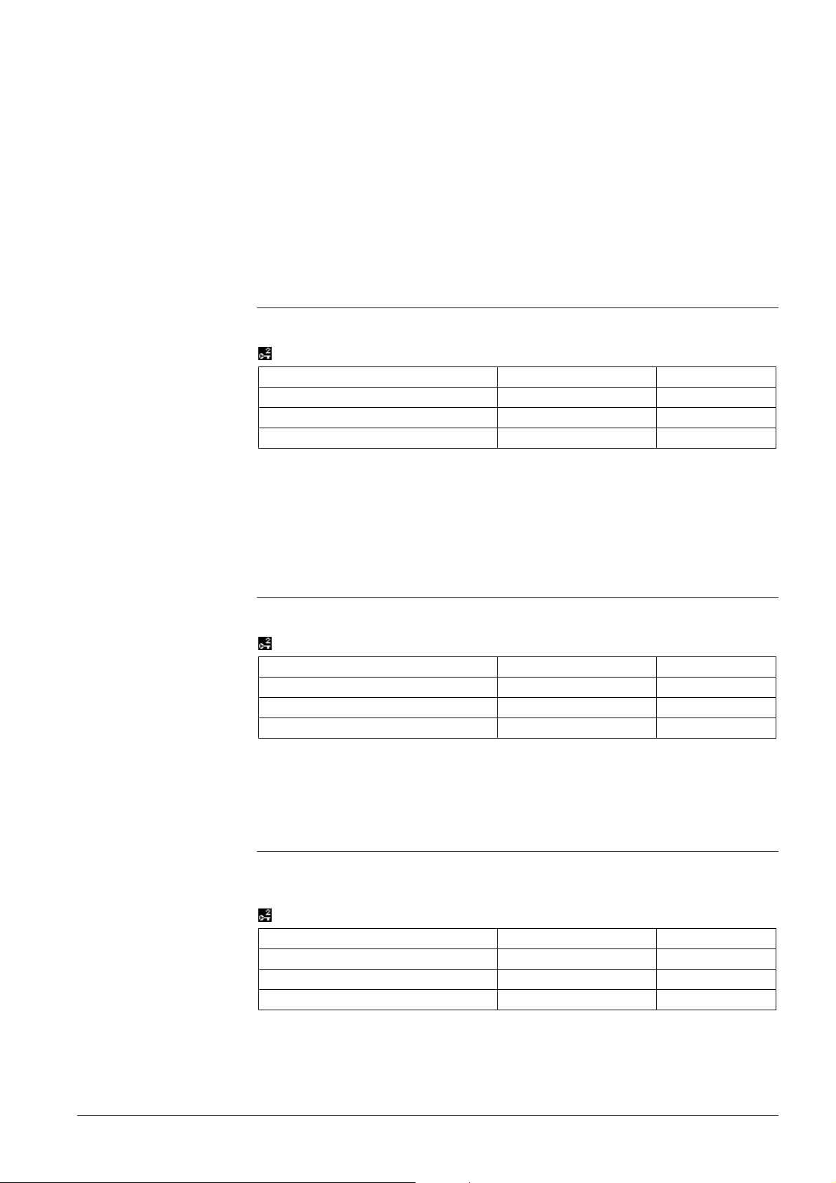
Main menu > Commissioning > Favorite pages > Add datapoints
Operating line Range Factory setting
Favorites 1 Favorites 1
…
Favorites 20
Main menu > Commissioning > Favorite pages > Add datapoints > Favorites 1 to Favorites 20
Operating line Range Factory setting
Datapoint name 1 …
…
Datapoint name 10 …
The favorite pages are presented with the title defined by the user. The factory setting
of the titles is Favorites 1…Favorites 20. Datapoints are presented with their names (copy
from the device menu tree). They can subsequently be renamed. Operating lines that
are not used appear as … .
Any datapoints from the menu trees of the devices on the device list can be assigned to
the favorite pages. The position – favorite page and line – can be freely selected. It is
also possible to overwrite existing datapoints by other datapoints. Subsequent sorting
of datapoints within the page is not possible.
Datapoints having a complex graphic display cannot be included in the favorites (time
switch, calendar, trend display, faults, etc.). Also, datapoints from the menus Commis-
sioning, Favorites, Favorite pages and Device list of the bus operator unit itself cannot be
included in the favorites either.
Operating mode Add datapoints is indicated by the
symbol in the corner at top right.
A datapoint is added according to the following procedure:
• Select the respective favorite page (1…20)
• Select the respective operating line (1…10)
• Select the device from the device list
• Navigate to the respective datapoint in the target device
• Select the datapoint with the OK knob
• Confirm adding with the OK knob and canceling with the ESC button
• Return automatically to the selected favorite page (OK knob), or return to the se-
lected datapoint (ESC button)
Operating mode Add datapoints is quit under the following conditions (
symbol extin-
guishes):
28/52
Building Technologies Bus operator unit RMZ792 CE1P3113en
HVAC Products 6 “Commissioning” menu 03.04.2006
Page 29
Note
Use
Operating lines
• A datapoint has been successfully assigned to a favorite page
• Navigation to the start page (press ESC buttons several times, or long press)
• Navigation to the Commissioning menu
• Navigation to the Favorites menu
• Navigation to the Favorite pages menu
• Navigation to the Device list menu
• No action for 30 minutes
All datapoints of the favorite pages can be operated from the user level, irrespective of
where they appear, in the bus user’s menu tree, on the user level, or on the service
level.
6.4.2 Submenu “Name datapoints”
Renaming the datapoints on a favorite page.
Main menu > Commissioning > Favorite pages > Name datapoints
Operating line Range Factory setting
Datapoint name 1 Max. 20 characters
…
Datapoint name 10 Max. 20 characters
When assigning datapoints from the menu tree of a device, the name of the data
source will be copied. The names of the datapoints on the favorite pages can be
changed, e.g. in the case of several datapoints within the same favorite page that carry
the same name. The bus operator unit will not automatically adopt a subsequent
change of name of the data source.
Use
Operating lines
Use
Operating lines
6.4.3 Submenu “Name favorites”
Naming the favorite page by using a self-explanatory title.
Main menu > Commissioning > Favorite pages > Name favorites
Operating line Range Factory setting
Favorite title 1 Max. 20 characters Favorites 1
…
Favorite title 20 Max. 20 characters Favorites 20
To simplify finding the correct favorite page, it is recommended to replace the default
title of a page by a self-explanatory name. The pages displayed must contain at least 1
datapoint.
6.4.4 Submenu “Sort favorites”
• Changing the order of favorite pages
• Putting frequently used favorite pages to the beginning of the list
Main menu > Commissioning > Favorite pages > Sort favorites
Operating line Range Factory setting
Favorite title 1 1…20
…
Favorite title 20 1…20
After a favorite page has been selected, its current position within the list of the presented favorite pages will be shown. By changing the value, the selected page can be
29/52
Building Technologies Bus operator unit RMZ792 CE1P3113en
HVAC Products 6 “Commissioning” menu 03.04.2006
Page 30
Notes
Use
Operating lines
Note
shifted to the required position. The position of each page can be freely selected
(1 = first page presented, 20 = last page presented). If the required position lies beyond
the current end of the list, the page will be placed in the last position.
• Prior to sorting the favorite pages, the default titles are to be replaced by selfexplanatory titles (refer to section 6.4.3 “Submenu “Name favorites””)
• If favorite pages are sorted based on the default titles, the datapoints will be correctly
resorted. But the title changes depending on the position and assignment to the favorite pages so that misunderstandings can arise
6.4.5 Submenu “Delete datapoints”
Deleting individual datapoints on a favorite page.
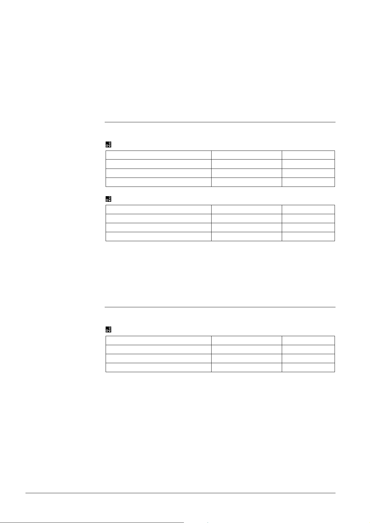
Main menu > Commissioning > Favorite pages > Delete datapoints
Operating line Range Factory setting
Favorite title 1 Favorites 1
…
Favorite title 20 Favorites 20
Main menu > Commissioning > Favorite pages > Delete datapoints > Favor ites 1 to Favorites 20
Operating line Range Factory setting
Datapoint name 1
…
Datapoint name 10
First, select the relevant favorite page and then delete the datapoint. Confirm the deletion by pressing the OK knob.
After deletion of the last datapoint, the empty favorite page is retained. The entire page
can be deleted via submenu Delete favorites.
Use
Operating lines
6.4.6 Submenu “Delete favorites”
Deleting individual favorite pages.
Main menu > Commissioning > Favorite pages > Delete favorites
Operating line Range Factory setting
Favorite title 1 Favorites 1
…
Favorite title 20 Favorites 20
After a security check is made, all favorite pages with their titles and all their datapoints
will be deleted. The favorite page is now empty, and menu Add datapoints can be used
to assign new datapoints.
30/52
Building Technologies Bus operator unit RMZ792 CE1P3113en
HVAC Products 6 “Commissioning” menu 03.04.2006
Page 31

Use
Operating lines
6.4.7 Submenu “Delete all favorites”
Deleting all favorite pages.
Main menu > Commissioning > Favorite pages > Delete all favorites
Operating line Range Factory setting
Delete all favorites --- / Deleted ---
After a security check is made, all favorite pages with their titles and all their datapoints
will be deleted.
31/52
Building Technologies Bus operator unit RMZ792 CE1P3113en
HVAC Products 6 “Commissioning” menu 03.04.2006
Page 32
Use
Function
7 Data backup
• Making a backup copy of the settings
• Restoring the safe settings after unsuccessful changes
• Securing or restoring the settings when changing the memory card
When commissioning is completed, the settings of the bus operator unit can be saved.
Later – e.g. after unauthorized changes or after inadvertent changes or deletions of
settings – these settings can simply be retrieved.
Data backup or restoration of data can take place at 2 different locations:
• Locally, that is, on the memory card (RMA792) of the bus operator unit
• On the second device, that is, on the memory card of a second bus operator unit
connected to the bus
Storage on a second device is especially practical when, for compatibility reasons, the
memory card of the bus operator unit must be replaced.
Data backup saves the following settings:
• Device list including the device name, order and display format
• Favorite pages with all datapoints
• Names and order of favorite pages
• Setting the display of fault status messages on the bus (refer to section 8.5 “Display
of bus fault status messages”)
All other settings (device address, language, etc.) will not be saved.
After successfully restoring all settings, the bus operator unit will be restarted.
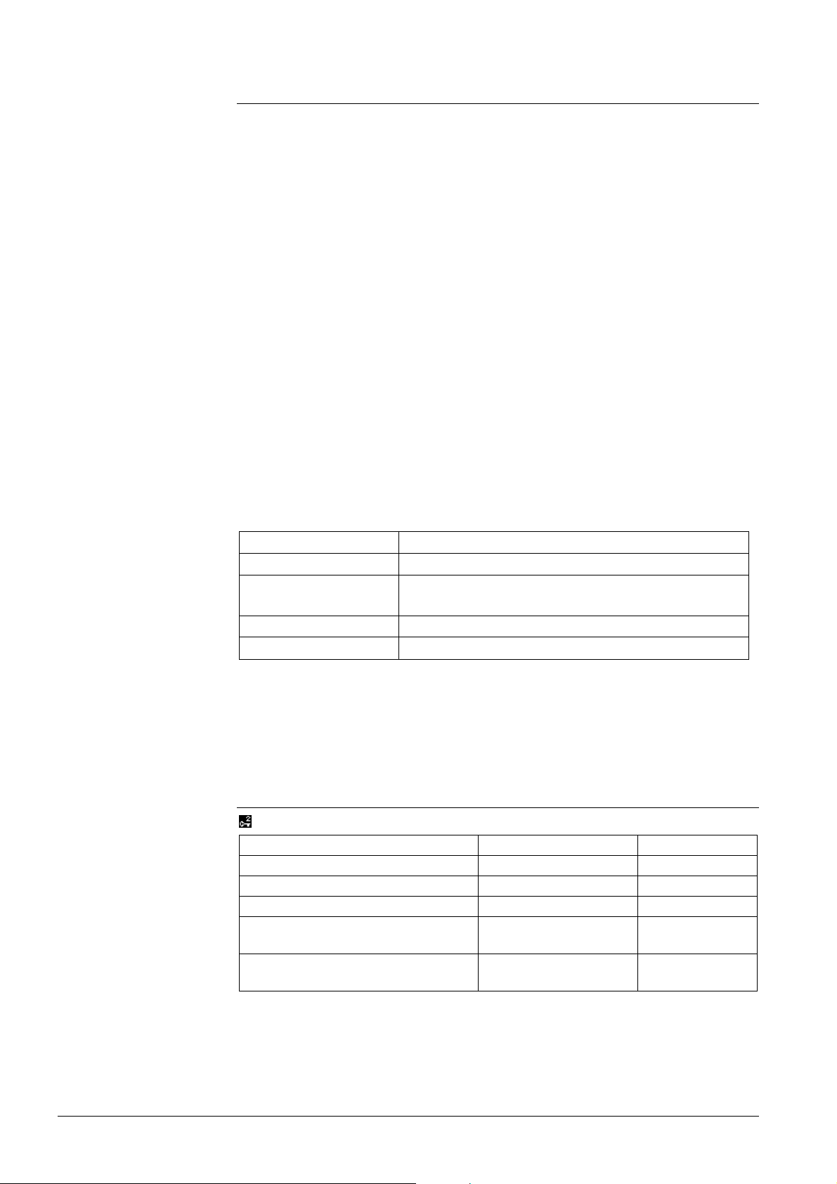
The following status messages will be displayed, depending on the action performed:
Note
Operating lines
Status messages Description
--- Command has not yet been executed
Restored
The settings have been successfully restored
Saved
The settings have been successfully saved
Failed An error occurred during data backup or data restoration
To avoid compatibility problems between the settings on the RMA792 memory card and
the RMZ792 bus operator unit, following rule must be observed:
The software version of the bus operator unit must be identical to or higher than
the software version with which the settings were saved.
7.1 Local data backup
Main menu > Data backup > Local
Operating line Range Factory setting
Restore --- / Restored / Failed --Save --- / Saved / Failed --Progress ---- / 0…100 % ---Storage date 01.01…31.12 Date of last
storage
Storage year 2000…2080 Year of last
storage
Operating line Save or Restore triggers the relevant copy process for the setting values.
The progress of the copy process is continuously displayed [0…100 %] and lasts about
15 seconds.
32/52
Building Technologies Bus operator unit RMZ792 CE1P3113en
HVAC Products 7 Data backup 03.04.2006
Page 33
Note
General
Operating lines
Operating lines
Notes
Storage date and Storage year only show sensible values if the bus operator unit received
a valid system time at the time of data backup.
7.2 Data backup on a second unit
Before the settings can be saved on a second bus operator unit, that unit must be
installed on the bus and be fully functioning. The second unit can also be located in
some other area or some other line of the network. The target address of the second
bus operator unit is to be set on submenu Address.
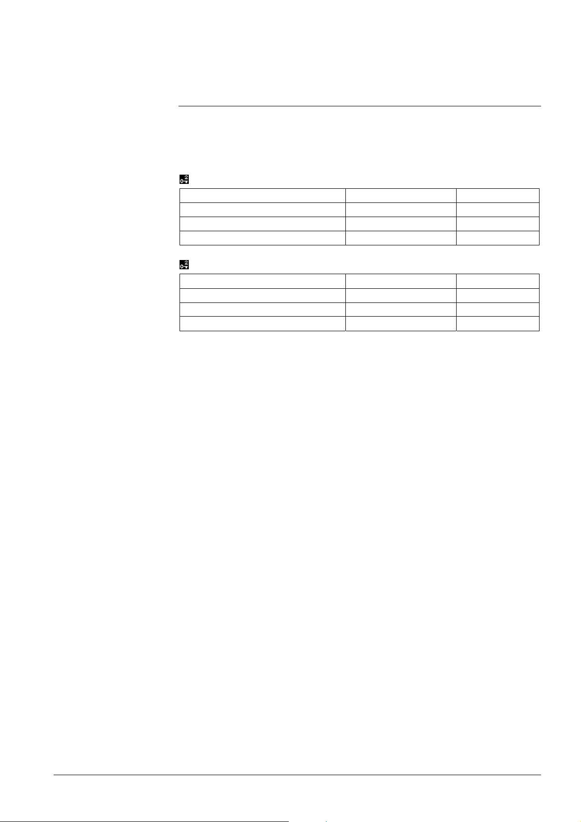
Main menu > Data backup > Second device > Address
Operating line Range Factory setting
Area 0…15 0
Line 0…15 2
Device address 1…255 255
Main menu > Data backup > Second device
Operating line Range Factory setting
Restore --- / Restored / Failed --Save --- / Saved / Failed --Progress ---- / 0…100 % ----
Operating line Save or Restore triggers the relevant transfer of the setting values. The
progress of the copy process is continuously displayed [0…100 %] and can last up to 3
minutes.
• When transferring data to the second bus operator unit, local data backup of the
second unit will be overwritten, which means that locally saved settings of the second unit will be lost. The date of local backup will be overwritten by the date on which
the data are transferred
• To avoid loss of data, the bus operator units involved must not be switched off or
removed during data transfer
• The bus operator unit cannot be used during the time data are transferred. To avoid
data corruption, simultaneous data backup or data restoration must not be performed
on the second unit
33/52
Building Technologies Bus operator unit RMZ792 CE1P3113en
HVAC Products 7 Data backup 03.04.2006
Page 34

7.3 Error handling
Possible cases
Error Cause / remedy
Save Failed
• Invalid address of the second unit
• Communication breakdown to the second
Progress ---- %
Setting not saved
unit
Remedy:
• Check bus connection and address of the
second unit
• Make a new data backup
Save Failed
• Communication breakdown or power failure
during data backup on the second unit
Progress 1…99 %
Settings incompletely saved
Remedy:
• Check bus connection and power supply
• Make a new data backup
Restore Failed
Setting not restored
No new start of bus operator unit
• Invalid address of the second unit
• Communication breakdown to the second
unit
Remedy:
• Check bus connection and address of the
second unit
• Restore data again
Restore Failed
Settings incompletely restored,
device list has been deleted
New start of bus operator unit
• Corrupted backup data
• Incompatible software version of backup data
• Communication breakdown or power failure
during data restoration on the second unit
Remedy:
• Check bus connection and power supply
• Use consistent and compatible backup data
• Restore data again
34/52
Building Technologies Bus operator unit RMZ792 CE1P3113en
HVAC Products 7 Data backup 03.04.2006
Page 35
Y
early clock
Selectable time formats
24 h
am/pm
Setting
Note
8 General settings
8.1 Time of day and date
The bus operator unit does not have its own yearly clock. If some other bus user (clock
time master) sends the time of day, the weekday and the date, that information will be
adopted and displayed by the bus operator unit. The correct operation of time switch,
calendars, etc., necessitates a clock time master.
8.1.1 Format
The following time formats are available:
• The date is displayed as dd.mm.yyyy (day.month.year).
Example: 31.05.2006
• The time of day appears as hh:mm (hours:minutes)
Example: 15:56
• The date is displayed as mm/dd/yy (month/day/year).
Example: 05/31/06
• The time of day is displayed as hh:mm am/pm (hours:minutes am/pm).
Example: 03:56 PM
Main menu > Settings > Device
Operating line Range Factory setting
Time format 24 hours
12 hours (am/pm)
Time of day and date are always displayed in the format of the bus operator unit, independent of the settings of the various bus users.
24 h
8.1.2 Setting
The bus operator unit can be used to readjust the system time of the clock time master
and thus the local display of time of day and date also.
Main menu > Time of day/date
Operating line Range Factory setting
Time of day 00:00…23:59 /
12:00am…11:59pm
Date 01.01. …31.12
Year 2000…2080
35/52
Building Technologies Bus operator unit RMZ792 CE1P3113en
HVAC Products 8 General settings 03.04.2006
Page 36
8.1.3 Error handling
Possible cases
Behavior whe n switching
on for the first time
Choice of languages
Setting
Notes
Error Cause / remedy
Time of day, weekday and date
are not shown on the start menu
• In the system, bus users do not send the
system time (there is no clock time master)
• The bus operator unit has not received any
system time telegram since it was switched
on
• Any of the line couplers does not forward the
telegram
The displays for the time switch,
calendar, etc., show the date
01.01.2000
8.2 Selecting the language
The bus operator unit has several languages loaded.
When switching the unit on for the first time, the Language menu appears (in English).
The language can also be changed later on during operation.
The following languages are available:
English ................. English
German.................German
Francais................French
Italiano..................Italian
Nederlands ...........Dutch
Polski....................Polish
Cesky....................Czech
Magyar..................Hungarian
Espanol.................Spanish
Dansk....................Danish
Norsk ....................Norwegian
Svenska................Swedish
Suomi....................Finnish
Ellinika ..................Greek
Russkij..................Russian
(Limba) Romana...Romanian
Slovensky .............Slovakian
Slovenski ..............Slovenian
Srpski....................Serbian
Hrvatski.................Croatian
Main menu > Settings > Device
Operating line Range Factory setting
Language English, German, … English
• With the exception of user-defined text, all operating text is always displayed in the
language selected on the bus operator unit, independent of the settings made by the
different bus users
Exception: User-defined text and fault text from other bus users is displayed unchanged
• Heterogeneous language selections made on the bus operator unit and by the bus
users can lead to the display of illegible, erroneous text. The language selection for
the plant concerned should be the same
36/52
Building Technologies Bus operator unit RMZ792 CE1P3113en
HVAC Products 8 General settings 03.04.2006
Page 37
Setting
Note
Setting
• With the bus operator unit, it is also possible to change the language of a bus user
(Synco™ 700 controllers type RMx7…). The language is selected via the device list
on the respective menu of the bus user. If the selected language does not exist with
the bus user, a change to English is made.
8.3 Selecting the unit of temperature
The units of temperature that can be selected for the bus operator unit are °C (or K)
and °F:
Main menu > Settings > Device
Operating line Range Factory setting
Unit °C / °F °C
Temperatures are always displayed with the unit selected on the bus operator unit,
independent of the settings made by the various bus users.
8.4 Contrast of display on the operator unit
The contrast of the display can be matched to the environmental conditions.
Main menu > Settings > Device
Operating line Range Factory setting
Contrast 0…100 % 50 %
Setting
Entries
8.5 Display of bus fault status messages
The following parameter defines the fault status messages displayed on the menu or
info page Fault status message bus.
Main menu > Settings > Faults
Operating line Range Factory setting
Fault status message bus Device list only / All
devices
Device list only
• Device list only:
Fault status messages are only displayed by devices contained on the device list.
• All devices:
Fault status messages are displayed by all Synco™ devices on the Konnex network.
Faults of devices not contained on the device list can neither be acknowledged nor
reset; also, they are not indicated by the fault LED.
8.6 Text entries
Both the device name of the bus operator unit and the business card can be freely
defined. The device name is shown on the start menu, the 4 text lines of the business
card are displayed in the form of an info picture.
Main menu > Settings > Texts
Operating line Range Factory setting
Device name Max. 20 characters
Business card line 1 Max. 20 characters
Business card line 2 Max. 20 characters
Business card line 3 Max. 20 characters
Business card line 4 Max. 20 characters
37/52
Building Technologies Bus operator unit RMZ792 CE1P3113en
HVAC Products 8 General settings 03.04.2006
Page 38
Settings
Important!
8.7 Password
Each of the 3 operating levels (User level, Service level and Expert level) can be protected
against unauthorized access through the use of passwords. The expert level is the
password level used by the bus operator unit. For the bus operator unit, the terms
“Password level” and “Expert level” have the same meaning.
Main menu > Settings > Passwords
Operating line Range Factory setting
User level 0…9999 0, that is, no
password
Service level 0…9999 0, that is, no
password
Expert level 1…9999 7
The passwords can only be changed on the password level. Setting value 0 means “no
password”, indicating that no password is required when accessing the respective
operating level.
The password required for the password level should be kept in a safe location! If the
password is lost, it will not be possible to retrieve the factory settings!
8.8 Device list
Certain menus for editing the device list are available both on the password level and
the less protected service level. Functionality on the service level is restricted to sorting,
naming and renaming devices, and to selecting the way of presentation.
Main menu > Device list > Sort list
Main menu > Device list > Name devices
Main menu > Device list > Display list
Main menu > Device list > List information
The individual functions are described in chapter 5 “Commissioning”.
8.9 Favorite pages
Certain menus for editing the favorite pages are available both on the password level
and the less protected service level. Functionality on the service level is restricted to
sorting, naming or renaming favorite pages and datapoints.
Main menu > Favorite pages > Name datapoints
Main menu > Favorite pages > Name favorites
Main menu > Favorite pages > Sort favorites
The individual functions are described in chapter 5 “Commissioning”.
38/52
Building Technologies Bus operator unit RMZ792 CE1P3113en
HVAC Products 8 General settings 03.04.2006
Page 39

9 Device information
Menu Device information provides information about the current version of the bus operator unit.
Displays
Main menu > Device > Device information
Operating line Remarks
Software version Display of type reference of bus operator
unit (RMZ792)
Software version Display of software version of bus operator
unit
Hardware version Display of hardware version of bus operator
unit
Memory card type Display of type of memory card (RMA792)
Memory card version Display of software version of memory card
If the bus operator unit is not able to address certain devices (error message Device
version not supported), it is recommended to compare the memory card version of the
bus operator unit and the software version of the respective device with the current
Valid Version Set (VVS). Exchange of the memory card by a new version is described
in section 11.2 “Exchanging the memory card”.
39/52
Building Technologies Bus operator unit RMZ792 CE1P3113en
HVAC Products 9 Device information 03.04.2006
Page 40
Note
10 Faults
As a matter of principle, the bus operator unit only handles faults of devices
contained on the device list.
When starting up, it can take up to 3 minutes for the device fault information to be
updated, depending on the size of the device list.
When using network topologies with line couplers, it must be made certain that the line
couplers forward correctly the devices’ fault information (LTE broadcast) to the bus
operator unit (filter tables must be appropriately configured).
10.1 Display of faults
Fault status messages delivered by the bus users are displayed by the bus operator
unit on a number of menus. Faults can be acknowledged by the bus operator unit and –
if permitted by the respective device – can also be reset.
The fault LED in the fault button flashes or is lit when faults are pending:
State of LED Description
LED dark No faults pending
LED flashes Unacknowledged faults
LED lit Fault still pending or not yet reset
The state of the LED (flashing / steady on) can differ between the bus operator unit and
a bus user if a fault relay has been configured on the operator unit.
Additional information about faults is given at different locations:
Location Description
Info page Fault status message bus Display of the most severe error (also refer
to subsection 10.1.3 “Info page and menu
“Fault status message bus””
Device list on the Main menu Fault symbol indicating faulty devices
Menu Faults current List of a maximum of 20 faults sorted by
priority, state of acknowledgement and date
/ time of day
Menu Fault status message bus Display of the most severe fault (also refer
to subsection 10.1.3 “Info page and menu
“Fault status message bus””
Fault menus of the respective de-
vices
Fault information from the local fault menus
in the menu tree of the respective control-
lers or devices (e.g. fault history)
The type of acknowledgement of a fault status message is determined by the fault
source (e.g. Synco™ 700 controller). Depending on the type of acknowledgement
demanded, a fault status message is acknowledged in one of the 3 following ways:
Type of acknowledgement Description
None Fault must neither be acknowledged nor
reset. The fault status message disappears
automatically when the cause of the fault
has been removed
Acknowledge The fault is displayed until it is acknowl-
edged (even if in the meantime, the cause
of the fault has been removed)
Acknowledge and reset The fault must first be acknowledged and,
after removal of the cause of fault, reset
40/52
Building Technologies Bus operator unit RMZ792 CE1P3113en
HVAC Products 10 Faults 03.04.2006
Page 41
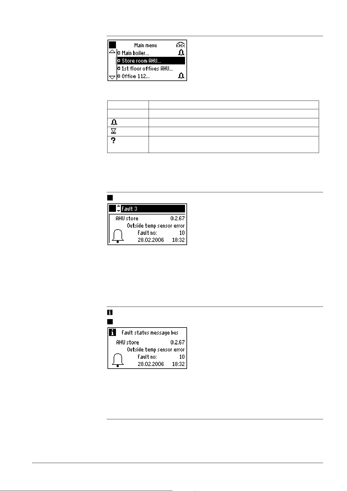
10.1.1 Device list on the “Main menu”
Note
The fault state of the devices is shown on the main menu by a symbol on the right hand
side. The symbols have the following meaning:
Fault symbol Description
Device in order, no fault pending
Device faulty
Device reads information about the fault
Possibility of device failure, information about fault cannot be read
or is not periodically forwarded
After starting up the bus operator unit, it can take up to 3 minutes for the fault state of
all devices to be updated, depending on the size of the device list.
10.1.2 Menu “Faults current”
Main menu > Faults > Faults current
This menu combines a maximum of 20 pending faults. The faults are sorted by fault
priority.
The order of fault status messages on the fault lists of Synco™ controllers and the bus
operator unit can differ, depending on priority information.
10.1.3 Info page and menu “Fault status message bus”
Fault status message bus and
Main menu > Faults > Fault status message bus
The above example shows a “most severe fault” of all devices on the device list or of all
Synco™ devices in the entire Konnex network. The display depends on the setting
described in section 8.5 “Display of bus fault status messages”.
10.2 Faults of non-listed bus users
Fault status messages from bus users not contained on the device list are handled
differently (refer to section 8.5 “Display of bus fault status messages”, depending on the
setting of parameter Fault status message bus:
41/52
Building Technologies Bus operator unit RMZ792 CE1P3113en
HVAC Products 10 Faults 03.04.2006
Page 42

Notes
Notes
• Setting Device list only:
Fault status messages from non-listed bus users will be ignored.
• Setting All devices:
If, at present, the fault status message from a non-listed bus user is the most severe
pending, it will only appear on the menu and on info page Fault status message bus.
The fault LED will not be lit. Acknowledgement and reset with the fault button is not
possible and must be made locally on the respective device.
10.3 Acknowledgement of faults
When pressing the flashing fault button, all faults to be acknowledged will be acknowledged. Only faults of devices from the device list will be acknowledged. Acknowledgement can take place from any of the menus.
• When a device list is full, acknowledgement of faults can take up to 1 minute
• Faults of Synco™ devices not contained on the device list cannot be acknowledged
10.4 Resetting faults
Only faults of devices from the device list can be reset. In contrast to fault acknowledgements, faults must be reset on an individual basis. A reset is made by pressing the
illuminated fault button.
To ensure that the fault and the reset command can be unambiguously assigned,
resetting of the current or the displayed fault can only take place on the following menus:
• On info page Fault status message bus of the bus operator unit
• On menu Fault status message bus of the bus operator unit
• On menu Faults current (faults 1…20) of the bus operator unit
• On the Main menu of the bus operator unit when the faulty device has been selected
• Locally on the faulty device (by pressing the fault button)
• Faults of Synco™ controllers can be reset via the bus operator unit only if setting
Remote reset of fault is activated.
Example of universal controller type RMU710:
Main menu > Commissioning > Communication > Basic settings
• Faults of Synco™ devices not contained on the device list cannot be reset.
10.5 Deleting faults
The fault history of a controller cannot be deleted from the bus operator unit; this is only
possible locally on the actual bus user.
42/52
Building Technologies Bus operator unit RMZ792 CE1P3113en
HVAC Products 10 Faults 03.04.2006
Page 43
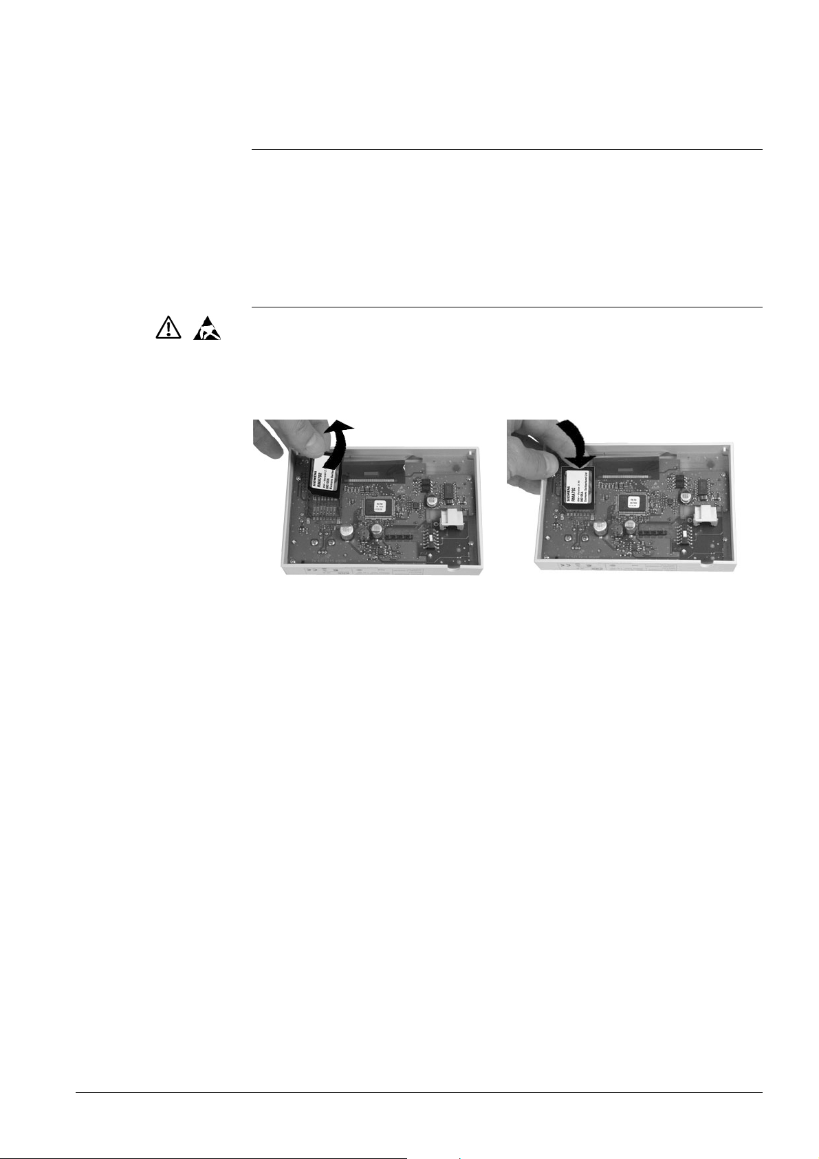
11 Memory card
11.1 Content of memory card
The exchangeable RMA792 memory card contains text catalogs in different languages
and the device descriptions of the bus users. The version of the bus user and that of
the respective device description must accord. For new versions or new types of Synco™ devices, the memory card must be updated, that is, exchanged.
If incompatible, the bus operator unit will display an appropriate error message.
11.2 Exchanging the memory card
To exchange the memory card, the bottom of the housing must be opened. The memory card must be exchanged when power is disconnected. The memory card can be
removed and replaced with no need for using a tool. When the unit is open, protective
ESD measures must be observed; the electronic components on the printed circuit
board must not be touched.
Removing the memory card Fitting the memory card
43/52
Building Technologies Bus operator unit RMZ792 CE1P3113en
HVAC Products 11 Memory card 03.04.2006
Page 44
12 Support in the event of errors and
faults
12.1 Error code list
The list only covers the errors that can result from the connection and operation of the
bus operator unit. For notes relating to other error codes, refer to the descriptions of the
respective devices.
Number Cause of error / fault Effect
6001 >1 identical device address Urgent message; must be
acknowledged
12.2 Rectification of errors
Error / error message Cause / remedy
When creating the device list (Create list, Add
devices), devices outside the search range will
also be included on the list
Caution!
Device version not supported
Caution!
Device not responding
Datapoint shows a value that does not make
sense (e.g. room temperature 655.3 °C)
Datapoint setting shows no effect
Device switches itself off from time to time
Extremely faint backlit display
Operating values of bus users are not cor-
rectly displayed or cannot be changed
The device address
(area.line.address) of the bus
operator unit and / or of other bus
users does not match the current
bus topology.
Check the device addresses and, if
required, make corrections
Version of bus operator unit’s
device description and software
version of the target device do not
match.
• Find compatible versions of
memory card and device (VVS)
• Exchange memory card
(RMA792) of bus operator unit or
target device
Communication with the target
device is not possible.
• Is the device in operation?
• Is the device connected to the
Konnex bus?
• Has the device address been
changed?
Device does not support information describing what is visible;
datapoint has no meaning in the
current configuration
Device does not support information describing what is visible;
datapoint has no effect in the current configuration
• Bus operator unit is powered via
Konnex. Bus power supply is
undersized and is not able to
power the bus operator unit. Use
more powerful supply, or
• Use external AC 24 V power
supply for the bus operator unit
44/52
Building Technologies Bus operator unit RMZ792 CE1P3113en
HVAC Products 12 Support in the event of errors and faults 03.04.2006
Page 45

Error / error message Cause / remedy
During commissioning, the wrong language
was selected. How do I find “my” language?
1. Press simultaneously the ESC
button and the OK knob.
2. Select the password level, enter
112 as the password (same no.
as international emergency call)
and confirm by pressing the OK
knob. The language changes to
English.
3. Go to menu Settings > Device >
Language to change to the required language.
Start menu does not show time of day, weekday and date
• No bus user in the system uses
the system time (no clock time
master)
• Since it was switched on, the
bus operator unit has received
no system time telegram
• Any of the line couplers does not
forward (filter) the telegram
The views of time switch, calendar, etc., show
the date 01.01.2000
Fault information from room controllers (e.g.
RXB2…) is not available(display “?” on the
device list)
The controller only communicates
in S-mode. Set communication of
the room controller with the ETS or
ACS to LTE mode and S-mode
Controller does not accept the Room number or
the Device name of the individual room controller (e.g. RXB2…)
The Room number may comprise no
more than 5 characters, the Device
name no more than 10 characters.
Text entries must be appropriately
shortened
Bus operator unit cannot reset the fault status
message from a controller
Remote reset of faults is not permitted. Make appropriate setting on
the controller (refer to section 10.4
“Resetting faults”).
45/52
Building Technologies Bus operator unit RMZ792 CE1P3113en
HVAC Products 12 Support in the event of errors and faults 03.04.2006
Page 46
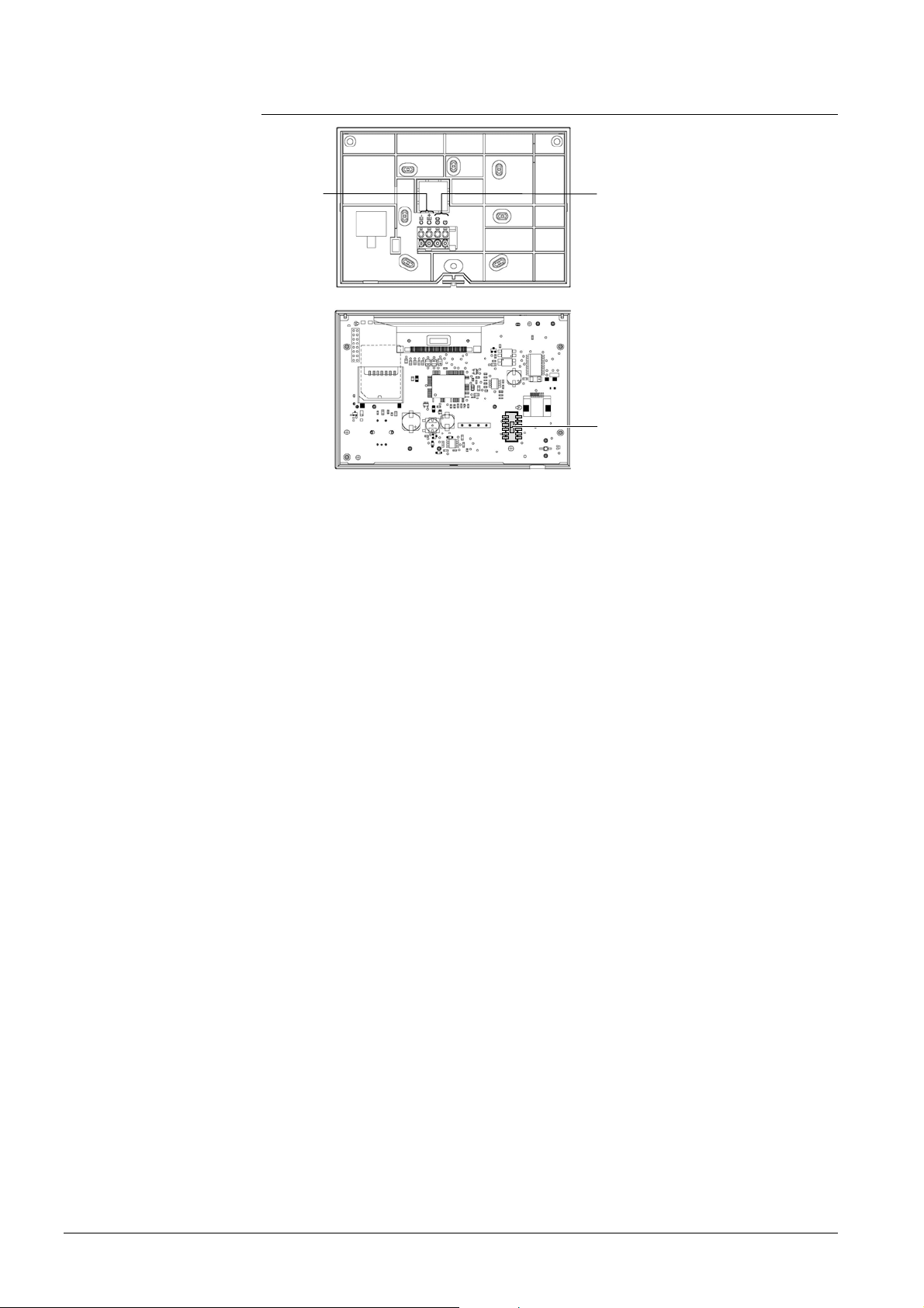
13 Electrical connections
3113Z58
Note
CE+
CE-
G0
G
3113Z57
S
G, G0 Connection terminals for AC 24 V operating voltage
CE+ Connection terminals for Konnex bus data line (positive)
CE− Connection terminals for Konnex bus data line (negative)
KNX Socket for Konnex bus (RJ45)
S Slide switch for selecting the type of power supply
KNX: Power supply via Konnex bus (45 mA)
EXT: External power supply via G, G0 (AC 24 V)
Ensure that the slide switch is in its correct position (KNX or EXT), depending on the
type of power supply (refer to chapter 4 “Power supply”).
46/52
Building Technologies Bus operator unit RMZ792 CE1P3113en
HVAC Products 13 Electrical connections 03.04.2006
Page 47
14 Appendix
14.1 Abbreviations used in this document
The following list contains the abbreviations most frequently used (in alphabetical
order):
Abbreviation Meaning
AC Alternating Current
ACS ACS7… commissioning and operating software
EIB European Installation Bus (will be replaced by Konne x)
ETS Engineering Tool Software (Konnex / EIB)
KNX Konnex bus connection (for operation and process information)
LTE mode New communication standard used by Synco and RXB
S-mode Like EIB up to now
LCD Liquid Crystal Display
LED Light Emitting Diode
MMI Man Machine Interface
SNA Konnex Subnetwork Address (area and line)
VVS Synco Valid Version Set, list of compatible versions
14.2 Editable text
The list with editable text shall serve as an aid for engineering and commissioning.
Maximum length of the text is 20 characters.
Main menu > Settings > Texts
Name of datapoint User-defined text
Device name
Business card line 1
Business card line 2
Business card line 3
Business card line 4
Main menu > Commissioning > Device list > Name devices
Name of datapoint User-defined text
Device name 1
Device name 2
Device name 3
Device name 4
Device name 5
Device name 6
Device name 7
Device name 8
Device name 9
Device name 10
…
Device name 150
47/52
Building Technologies Bus operator unit RMZ792 CE1P3113en
HVAC Products 14 Appendix 03.04.2006
Page 48
Main menu > Commissioning > Favorite pages > Name favorites
Name of datapoint User-defined text
Favorite title 1
Favorite title 2
Favorite title 3
Favorite title 4
Favorite title 5
Favorite title 6
Favorite title 7
Favorite title 8
Favorite title 9
Favorite title 10
…
Favorite title 20
Main menu > Commissioning > Favorite pages > Name datapoints
Favorites 1…Favorites 20
Name of datapoint User-defined text
Datapoint name 1
Datapoint name 2
Datapoint name 3
Datapoint name 4
Datapoint name 5
Datapoint name 6
Datapoint name 7
Datapoint name 8
Datapoint name 9
Datapoint name 10
48/52
Building Technologies Bus operator unit RMZ792 CE1P3113en
HVAC Products 14 Appendix 03.04.2006
Page 49

Index
A
abbreviations.............................................................47
acknowledge faults ...................................................42
acknowledgement of faults .......................................42
ACS...........................................................................47
activating communication..........................................22
add devices...............................................................26
adding datapoints to favorite pages..........................28
adding devices..........................................................26
address assignment manual.....................................21
address assignment with the ETS ............................21
address search .........................................................21
area...........................................................................22
assignment of addresses..........................................22
automatic address search.........................................21
B
backup copy..............................................................32
bus users ..................................................................15
business card............................................................37
business card line.....................................................47
C
central power supply.................................................18
commissioning..........................................................20
commissioning menu................................................21
communication..........................................................22
connection terminals.................................................46
contrast of display.....................................................37
create device list.......................................................24
creating the device list . .............................................24
D
data backup ........................................................32, 34
data backup on second unit......................................33
datapoints of favorite pages......................................27
delete all favorite pages............................................31
delete device list .......................................................26
delete devices...........................................................26
delete faults...............................................................42
delete favorites..........................................................30
deleting datapoints on favorite pages.......................30
deleting devices........................................................26
deleting faults............................................................42
deleting favorite pages..............................................30
deleting the device list...............................................26
device address....................................................21, 22
device descriptions .........................................7, 16, 43
device information.....................................................39
device list............................................................23, 38
device list on the main menu ....................................41
display contrast.........................................................37
display faults .............................................................41
display format type of display....................................27
display of bus fault status message ..........................37
display of faults .........................................................40
display the device list ................................................27
E
editable text...............................................................47
editing text.................................................................47
electrical connections................................................46
entry of text ...............................................................37
error code list ............................................................44
error handling..........................................16, 19, 22, 34
error handling time of day .........................................36
ESC button................................................................11
ETS ...........................................................................21
external power supply ...............................................18
F
fault button ................................................................11
fault history................................................................42
fault status message bus ..........................................37
faults of non-listed bus users ....................................41
favorite pages............................................................38
favorites...............................................................16, 27
format clock...............................................................35
H
hardware version.......................................................39
I
info button .................................................................11
info level....................................................................12
info page ...................................................................41
information describing what is visible........................16
K
key features.................................................................9
L
language catalogs.....................................................43
language selection ....................................................36
leaving the password level........................................20
line.............................................................................22
line coupler................................................................21
list error.....................................................................27
list information...........................................................27
list of error codes.......................................................44
local data backup ......................................................32
local operation...........................................................15
long text.....................................................................15
loss of password .......................................................38
LTE mode..................................................................47
49/52
Building Technologies Bus operator unit RMZ792 CE1P3113en
HVAC Products Index 03.04.2006
Page 50

M
manual assignment of addresses..............................21
memory card .........................................................7, 43
menu tree............................................................12, 13
N
name datapoints........................................................29
name devices............................................................25
name favorites...........................................................29
naming datapoints.....................................................29
naming the devices ...................................................25
naming the favorite pages.........................................29
navigation..................................................................15
non-listed faults.........................................................41
O
operating elements....................................................11
operating levels.........................................................12
operation ................................................................... 11
operation of devices..................................................15
operator unit functions...............................................11
operator units ..............................................................7
P
password level...............................................12, 20, 38
passwords.................................................................38
polarity CE+ / CE–.....................................................19
power supply via Konnex bus....................................18
power supply via Synco controller.............................19
product documentation................................................8
product range............................................................15
programming mode.............................................21, 22
second unit for data backup ..................................... 33
select-and-press knob.............................................. 11
selecting the language........................................ 20, 36
service level........................................................ 12, 38
setting the time of day .............................................. 35
S-mode.....................................................................47
SNA.......................................................................... 47
software version ....................................................... 39
sort device list........................................................... 24
sort favorites.............................................................29
sorting automatically................................................. 24
sorting favorites........................................................ 29
sorting manually ....................................................... 24
sorting the device list................................................24
start page.................................................................. 12
state of list ................................................................ 27
status messages....................................................... 23
storage date.............................................................. 33
storage year.............................................................. 33
subnetwork address ................................................. 21
T
text catalog................................................................. 7
text entries................................................................ 37
time format clock ...................................................... 35
time of day and date.................................................35
time of day error handling......................................... 36
time-of-day format .................................................... 35
time-of-day setting....................................................35
topology......................................................................8
type of device ........................................................... 39
type of memory card................................................. 39
R
rectification of errors..................................................44
rectifying errors..........................................................44
reset faults.................................................................42
resetting faults...........................................................42
restore.......................................................................33
S
safety.........................................................................10
U
unit of temperature ................................................... 37
user level............................................................ 12, 38
user-defined text....................................................... 17
V
VVS .......................................................................... 47
50/52
Building Technologies Bus operator unit RMZ792 CE1P3113en
HVAC Products Index 03.04.2006
Page 51

51/52
Building Technologies Bus operator unit RMZ792 CE1P3113en
HVAC Products 03.04.2006
Page 52

Siemens Switzerland Ltd
Building Technologies Group
International Headquarters
HVAC Products
Gubelstrasse 22
CH- 6301 Zug
Tel. +41 41 724 24 24
Fax +41 724 35 22
www.sbt.siemens.com
52/52
Building Technologies Bus operator unit RMZ792 CE1P3113en
HVAC Products 03.04.2006
© 2006 Siemens Switzerland Ltd
Subject to alteration
 Loading...