

Page 1
Control Series
Technical Instructions
SSD Electronic Valve Actuators
Spring Return
Non-Spring Return
Product Number
Description
Operating Mode
Actuator Prefix Code
Pressure Independent
Floating or 0 to 10 Vdc Control
Document No. 155-773
September 1, 2015
Description
Features
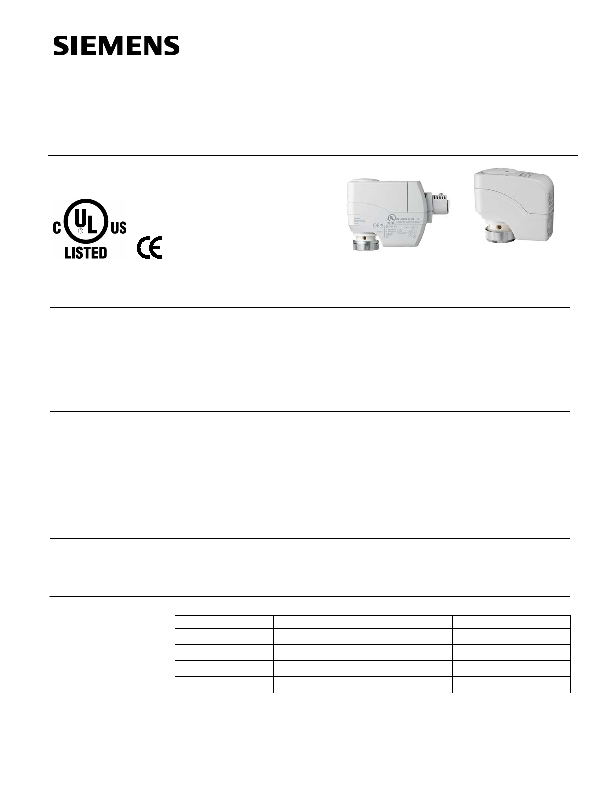
Pressure Independent Control Series SSD Electronic Valve Actuators require a 24 Vac
power supply and receive a floating control signal (SSD81…) or a proportional 0 to
10 Vdc signal (SSD61…) to control a valve. The 0 to 10V SSD61U actuator also
accepts a 24 Vdc power supply.
These actuators are designed to work with 1/2- to 1-1/4 inch Pressure Independent
Control Series Valves with a 1/10-inch (2.5 mm), 1/5-inch (5 mm), or 7/32-inch (5.5 mm)
stroke and a threaded valve bonnet that fits the actuator.
• Nominal force >56 lbs (250 N)
• Automatic stroke calibration on the SSD61…
• UL listed for plenum installation
• Reduced power consumption in holding position
• Direct coupled installation without tools (hand-tightened)
• Manual override
• Visual position indication
Application
For use in heating and cooling HVAC applications with Pressure Independent Control
valves. They can be used in chilled/hot water applications or in water-glycol solutions up
to 50% in closed loop systems. The Spring Return SSDx1.5U Series actuators accept
plenum cable or 3/8-inch flex conduit connections.
Product Numbers
SSD81U Floating Fail-in-place 230
Siemens Industry, Inc.
SSD61U 0 to 10 Vdc Fail-in-place 231
SSD81.5U Floating Fail-safe 232
SSD61.5U 0 to 10 Vdc Fail-safe 233
Table 1.
Page 2

Technical Instructions Pressure Independent Control
SSD81U
SSD61U
SSDx1.5U
Operating voltage Vac
24 Vac ±20%
24 Vac ±20%
24 Vac ±20%
Frequency
50/60 Hz
50/60 Hz
50/60 Hz
Operating voltage Vdc
—
24 Vdc ±25%
—
Power consumption
SSD81…
SSD61…
Control signal
Floating
0 to 10 Vdc
Output impedance
—
>100K ohm
Positioning accuracy 0 to 10 Vdc
—
<2% of
SSD81U
SSD61U
SSD81.5U
SSD61.5U
Run time (in seconds)
5/5.5 mm stroke
150
90
125
30
Spring return (in seconds)
5/5.5 mm stroke
— — 30
30
Nominal force
>56 lbs.
>56 lbs.
>67 lbs.
>67 lbs.
Capacitor charge time
—
—
180 max.
180 max.
Spring return
—
—
Non-mechanical,
UL Listed to UL873
Ambient temperature
Dimensions See Figure 13 and Figure 14.
Document No. 155-773 SSD Series Electronic Valve Actuators
September 1, 2015
Ordering
Information
Specifications
Power supply
Control Characteri stics
Function
To order a complete valve plus actuator assembly from the factory, combine the
actuator prefix code with the suffix of the valve product number. To order an actuator
only, use the product number.
Normal operation
At ultra cap load
0.8 VA max.
—
2.5 VA max.
—
2 VA
3 VA
nominal stroke
2.5 mm stroke 75 45 70 15
2.5 mm stroke — — 15 15
(250N)
(250N)
(300N)
(300N)
(in seconds)
(SSDx1.5U only)
electronic. Returns to stem
up (0 position).
Agency Certification
cUL Certified to Canadian Standard
C22.2 No. 24-93
Ambient Conditions
Operation 41°F to 122°F (5°C to 50°C)
Transport/Storage -13°F to 158°F (-25°C to 70°C)
Humidity
Operation 5 to 85% rh
Transport <95% rh
Storage 5% to 95% rh
Miscellaneous
Weight
SSDx1U 12.3 oz. (0.35 kg)
SSDx1.5U 1.3 lbs. (0.6 kg)
Page 2 Siemens Industry, Inc.
Page 3
Pressure Independent Control Technical Instructions
SSD Series Electronic Valve Actuators Document No. 155-773
September 1, 2015
Accessories
ASY98 Replacement screw and nut for use on the conduit connector or the terminal
connector, quantity one each. For SSD61U and SSD81U only.
Warning/Caution Notations
WARNING:
CAUTION:
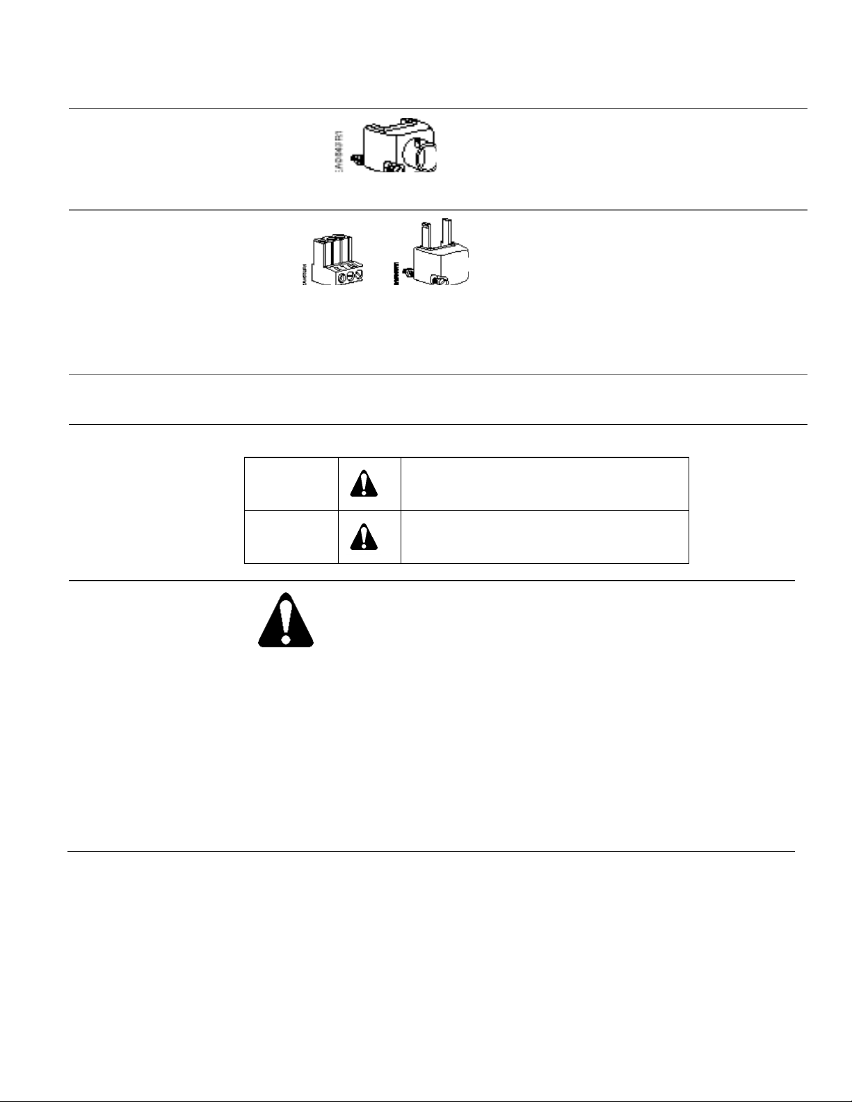
Figure 1. Conduit Connector .
Figure 2. Terminal Plug and
Block Cover.
Personal injury/loss of life may occur if you
do not perform a procedure as specified.
Equipment damage may occur if you do not
perform a procedure as specified.
ASY97 Conduit connector (quantity one).
For SSD61U and SSD81U only.
Terminal plug and terminal block cover
(quantity: one each). For SSD61U and
SSD81U only.
• ASY99 SSD81U actuator
floating control.
• ASY100 SSD61U actuator
0 to 10 Vdc control.
Operation
CAUTION:
A valve must be connected to the actuator before applying power.
If applying power to the actuator when a valve is not connected, the
actuator will respond to a control signal and the shaft will extend until it
reaches its maximum end stop. Thereafter, it will not respond to any
signal. If this occurs:
1. Disconnect power.
2. Turn the manual position indicator (see Figure 7) on the top of the
actuator to the 0 position and verify the actuator shaft completely
retracts.
3. Connect a valve to the actuator.
4. Reapply power. The actuator will return to normal operation.
Siemens Industry, Inc. Page 3
Page 4
Technical Instructions Pressure Independent Control
Calibration Stroke
CAUTION:
Figure 3.
Document No. 155-773 SSD Series Electronic Valve Actuators
September 1, 2015
Operation,
Continued
SSD81U
SSD61U
A 24 Vac control signal to terminal Y1 extends the actuator shaft proportionately to the
length of time the signal is applied.
A 24 Vac control signal to terminal Y2 retracts the actuator shaft proportionately to the
length of time the signal is applied.
In the event of a power failure with no control voltage, the non-spring return SSD81U will
hold its last position.
The SSD81U floating actuator does not self-calibrate.
The stroke travel on the SSD61U is proportional to the control signal Y. A zero voltage
control signal retracts the stem and returns the valve to its normal position. With no
supply voltage, the SSD61U actuator maintains its last position.
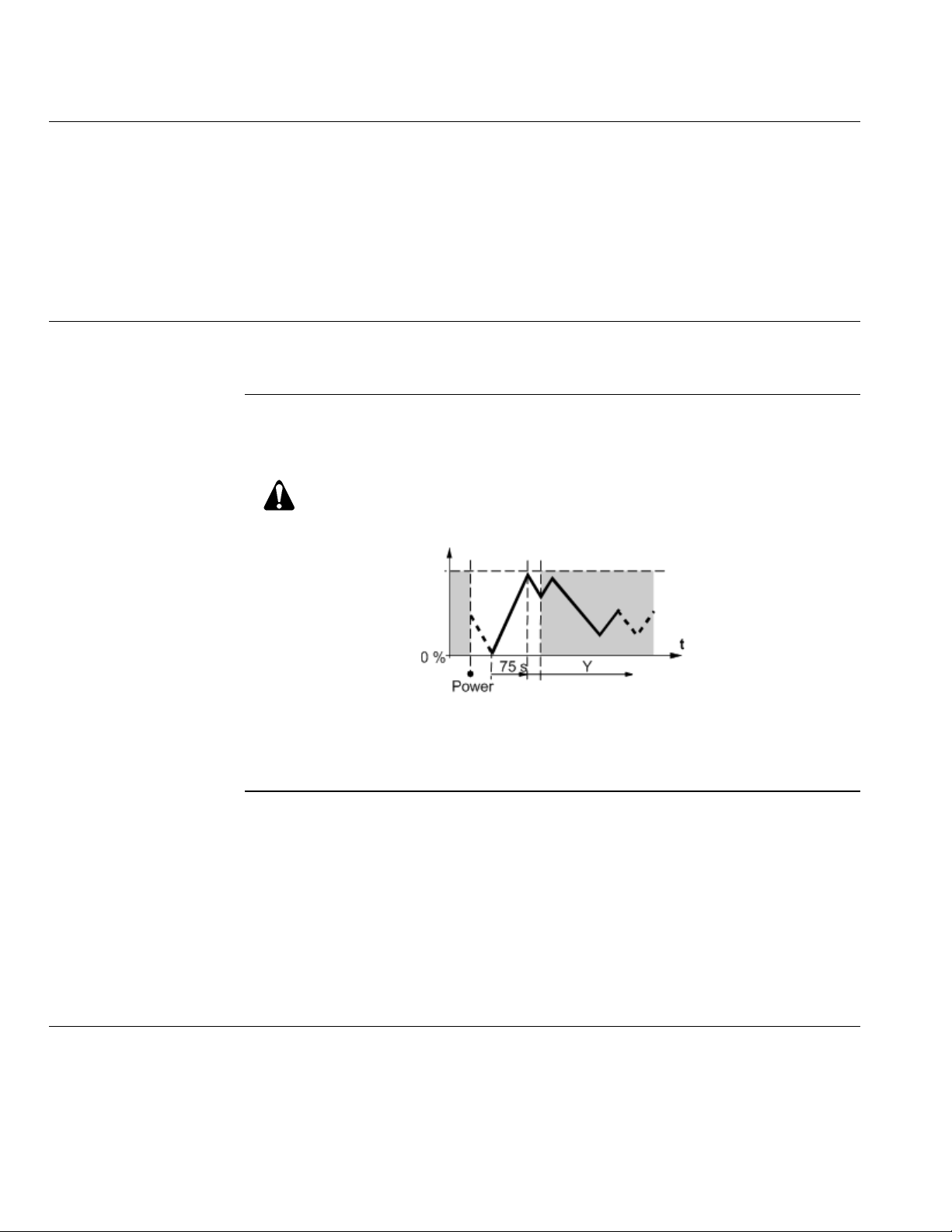
The SSD61U is equipped with a microprocessor to control the valve stroke length. The
actuator will complete a stroke calibration each time the power supply voltage is
connected.
Whenever the SSD61U runs a self-calibration routine (Valve stroke 0
Max. stroke Setpoint), do not manually intervene in this process. See
SSDx1.5U
Page 4 Siemens Industry, Inc.
Figure 3. SSD61U Self-Calibration.
NOTE: Correct calibration is possible only with valve strokes >1.5 mm. For valve
strokes <1.5 mm, the actuator/valve combination locks after three failed
calibration attempts.
For the SSD81.5U, a 24 Vac control signal to terminal Y1 extends the actuator shaft
proportionately to the length of time the signal is applied.
A 24 Vac control signal to terminal Y2 retracts the actuator shaft proportionately to the
length of time the signal is applied.
The stroke of the SSD61.5U is proportional to the control signal on terminal Y. A 0 Vdc
control signal retracts the stem and returns the valve to its normal position.
In the event of a power failure, the SSDx1.5U returns to the stem up, or normal position.
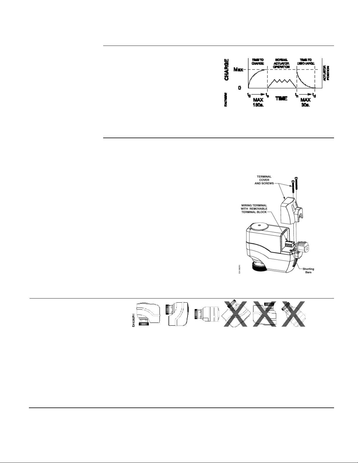
The SSDx1.5U includes an electronic return mechanism that functions as follows. See
Figure 4.
Page 5
Pressure Independent Control Technical Instructions
SSD Series Electronic Valve Actuators Document No. 155-773
September 1, 2015
Operation,
SSDx1.5U
Continued
• At power-up (t0), a capacitor must
charge to its maximum capacity (Max,
tc). This will take a maximum of 180
sec, during which time no actuator
movement occurs.
• Once the capacitor is fully charged (tc),
normal actuator operation occurs.
• If a subsequent power failure occurs
(tn) of greater than 5 seconds, the
capacitor discharges (td) and the
actuator spring returns to stem up 0
position.
Figure 4. SSDx1.5U Electronic Spring
Return Mechanism.
Calibration Stroke
SSD61.5U
Mounting and
Installation
The SSD61.5U writes its calibration stroke parameters to nonvolatile memory on the
first startup of the actuator. Successive startups bypass the calibration stroke unless the
memory is manually cleared. If installing the actuator on a different valve (such as on a
replacement valve), manually clear the calibration stroke from memory as follows:
1. Remove the terminal cover using a
Phillips head screwdriver.
2. Locate hole on the circuit board
shorting bars.
3. Insert and gently twist a flat-blade
screwdriver to electrically connect the
shorting bars (see Figure 5). The
SSD61.5U then performs a new
calibration stroke.
4. Secure the terminal cover back in
place.
Figure 5. Manually Clearing Calibration
Stroke from Memory.
Figure 6. Mounting Positions.
Mount the actuator in one of the allowable positions shown in Figure 6.
When mounting the actuator in a plenum, the proper cable must be attached to meet
local codes.
Allow 8 inches (200 mm) above the actuator and 8 inches (200 mm) behind the cable
for service.
Installation instructions are included with the actuator.
Siemens Industry, Inc. Page 5
Page 6
Technical Instructions Pressure Independent Control
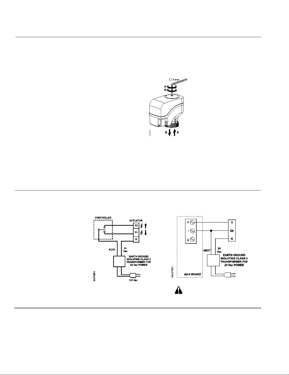
• (B) Turn hex wrench clockwise to extend the spindle.
• Do not use autotransformers. Use earth ground isolating step-down Class 2 power
Figure 8. SSD81U Wiring Diagram.
WARNING:
Figure 9. SSD61… Wiring Diagram.
Document No. 155-773 SSD Series Electronic Valve Actuators
September 1, 2015
Manual Override
The actuator can be driven manually to any position between 0 and 1 with a 3 mm hex
wrench. The control signal from the controller, however, will take priority over any
manual position.
For manual positioning (without power), insert the 3 mm hex wrench in the center of the
position indicator. See Figure 7. The actuator will maintain its position until power is
provided or restored.
Figure 7. Manual Override Operation.
• (A) Turn hex wrench counterclockwise to retract the spindle.
NOTE: Do not perform manual override while the power supply is connected; the
actuator will not track accurately when the control signal is applied. A short
power off/power on sequence is recommended to recalibrate the SSD61U
actuator.
Wiring
supplies.
• Determine supply transformer rating by summing total VA of all actuators used.
• It is recommended that no more than 10 actuators be powered by one transformer.
Terminal connection “G0” is
Common, not ground.
Page 6 Siemens Industry, Inc.
Page 7
Pressure Independent Control Technical Instructions
CAUTION:
actuator.
G, G0
24 Vac Operating Voltage
G
System Potential
G0
System Neutral
Y
0 to 10 Vdc Control Signal
Y1
Output shaft extends
Y2
Output shaft retracts
Start-
Check the wiring and the position indication.
the output shaft is retracted.
Extended Retracted
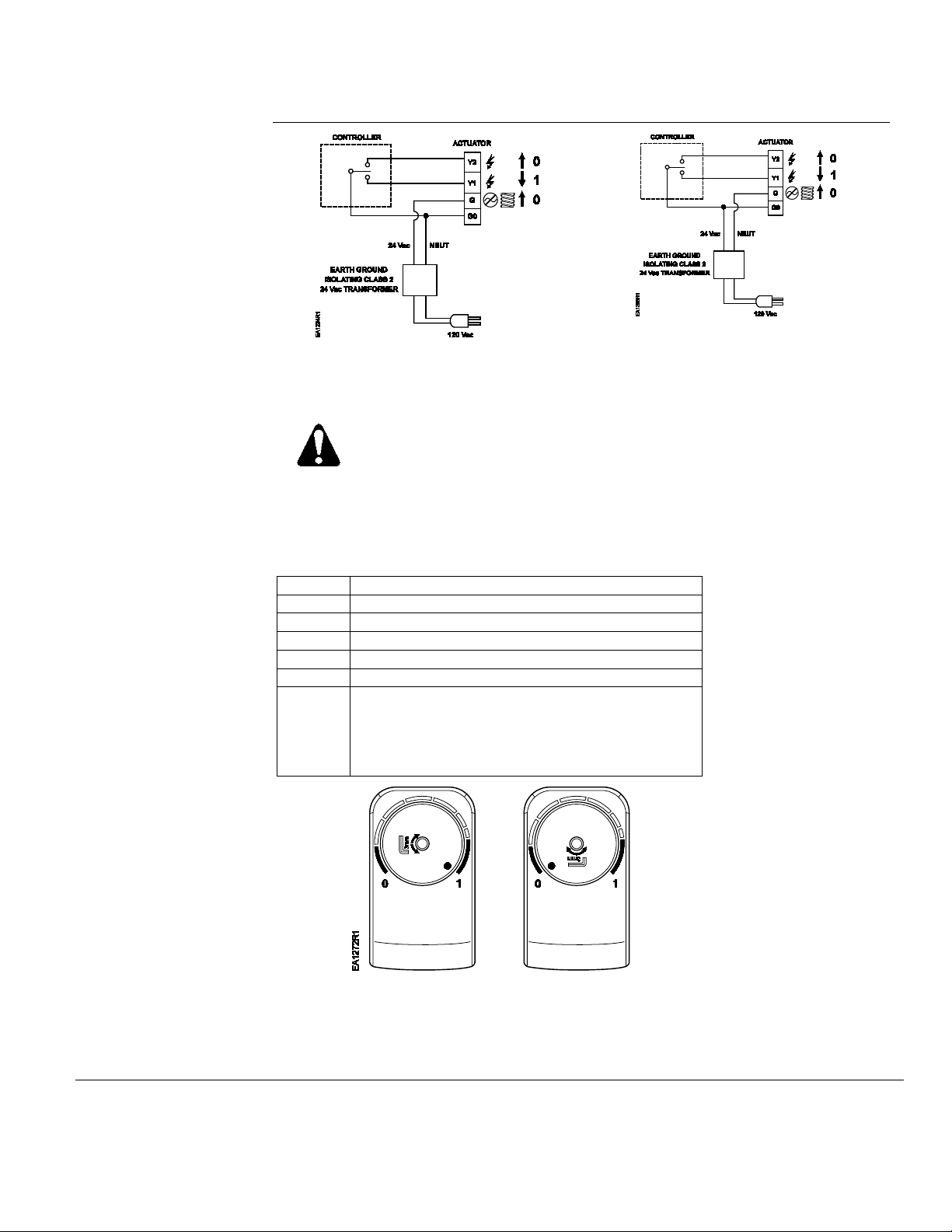
Figure 12. Position Indicator.
NOTE:
measurement.
SSD Series Electronic Valve Actuators Document No. 155-773
September 1, 2015
Wiring, Continued
Figure 10. SSD81.5U Neutral Switching
Spring Return.
NOTE: SSD81.5U can be wired either neutral or hot switched. For hot switching:
Terminals must be properly wired for correct function and full life of the
Figure 11. SSD81.5U Hot Switching
Spring Return.
G = System Neutral
G0 = System Potential
Table 2. Terminal Designations.
Up
When the position indicator is in the “1” position,
the output shaft is extended.
When the position indicator is on the “0” position,
Position Position
indicator at 1 indicator at 0
Actuator Stem Actuator Stem
Siemens Industry, Inc. Page 7
The "1" and "0"
position markings
are intended for
reference only and
not for stroke
Page 8
Technical Instructions Pressure Independent Control
Siemens Industry, Inc.
+1-847-215-1000
Your feedback is im port ant to us. If you have
Document No. 155-773
Document No. 155-773 SSD Series Electronic Valve Actuators
September 1, 2015
Troubleshooting
Dimensions
Check Wiring for proper connections.
If the actuator does not provide full flow or full close-off, check that the actuator is
properly attached to the valve.
If not:
1. Turn the power off.
2. Manually retract output shaft with 3mm wrench to zero position.
3. Tighten the bonnet ring onto the valve completely.
4. Power up.
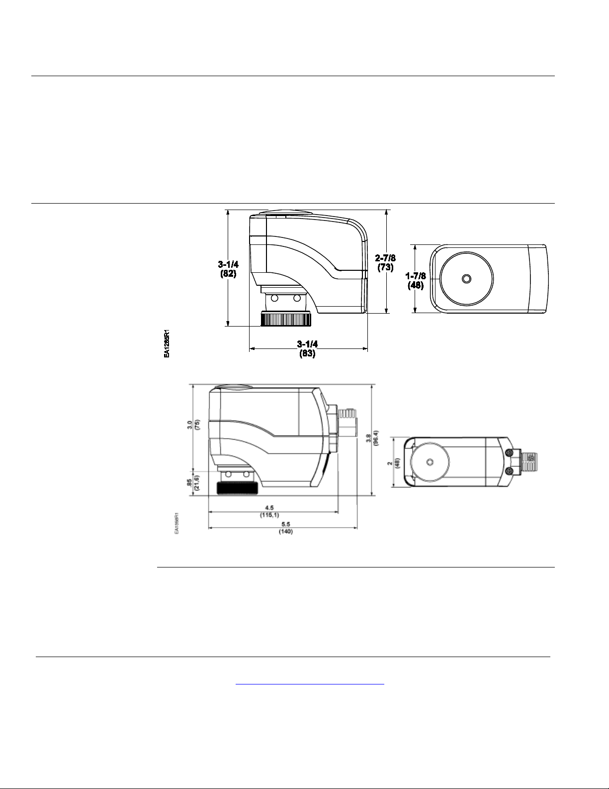
Figure 13. SSD Actuator Dimensions in Inches (Millimeters).
Figure 14. SSDx1.5U Actuator Dimensions in Inches (Millimeters).
Service Envelope
Information in this publication is based on current specifications. T he company reserves the right to make changes in specif ications and models as
design improvements are introduced. Product or company names mentioned herei n may be trademarks of thei r respective owners.
© 2015 Siemens Industry, Inc.
Building Technologies Divis i on
1000 Deerfield Parkway
Buffalo Grove, IL 60089-4513
USA
Minimum access space recommended:
8 inches (200 mm) above the actuator and beside the terminal plug.
comments about this document, please send them to
Printed in the USA
Page 8
 Loading...