

Siemens SAT 12, SMT 12 Installation Instructions Manual
s
SAT 12/SMT 12
SLT 12 UK
20 800 771.0-010
Installation instructions
Q
W
Fig. 1
U
T
Fig. 2
8AA11830 - E0 - 10/10/2003 - UK - SNR 811830.0-001
I
U
Fig. 3
Y
Q
W
E
R
Q
E-Bus
NC
B2
NC
B1-
B3
B4+
Y
Emply
Z4
Z3
O2
O1
3
1
2
T
Z2
7
8
6
4
5
R
W
Z1
E
9
1. Product description
This transponder is supplied either as an SAT 12 with
a housing or an SMT 12 without the housing.
2. Supply package
The SAT 12 package contains the following :
- One SAT 12 Housing (only SAT 12).
- One SMT 12 transponder (board).
- 8 terminating resistors (4.7 kOhm).
- One set (4 off) of mounting studs (only SMT 12).
- One SLT 12 language kit complete with :
- Installation instructions.
- One Wiring diagram.
- One cable with socket connector for external
tamper contact (only SMT 12).
3. Mounting instructions
The SAT 12 and SMT 12 are designed for mounting
in dry indoor rooms. They must not be exposed to
either dripping or splashing water. The SMT 12 is
designed for installation either in an power supply
unit or a suitable flush-type box.
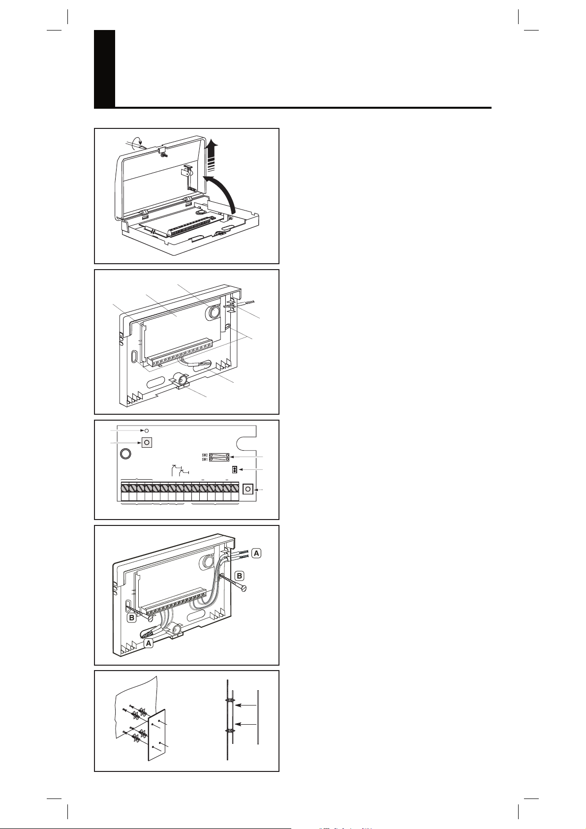
3.1 Open housing (fi g. 1)
1 - Slacken the retaining screw Q.
2 - Remove the cover W.
3.2 Product overview (fi g. 2)
Housing (SAT 12 only) with the following:
- Mounting holes W.
- Holes or knockouts Q,E for cables.
- Eye R for sealing.
- Locking tab T to hold the circuit board.
- SMT 12 circuit board Y.
- Knockout U for the back tamper contact screw.
3.2.1 SMT 12 circuit board (fi g. 3)
- Wire jumpers Q for programming glass break
alarm inputs.
- Plug connector W for external tamper contact,
connected in parallel to the tamper contact E.
- Tamper contact of SAT 12 housing E.
- Four inputs R.
- Two «open collector» outputs T.
- E-Bus connection Y.
- Address key U.
- LED I flash if the E-Bus communication is correct
3.3 Fit SAT 12 housing (fi g. 4)
1 - If necessary, break out the knockouts for
cables (A).
2 - Insert cables.
3 - Secure the base using 2 screws (B).
3.4 Fit SMT 12 circuit board
1 - Engage the mounting studs in the holes (fig. 5A).
2 - Fit circuit board (fig. 5B).
Fig. 4
Fig. 5
A
B
E-Bus from the
central control unit
Fig. 6
1. Normally open contact
2. Normally closed contact
4k7
3. Normally closed contact
monitored
Z1
SW 1
Z2
SW 2
Fig. 7
B3
B2
B1-
B4+
E-Bus to other
Input modes
Z
Z
Z
ClosedInput OpenSwitch
To connect a maximum
of 20 glass break sensors
4k7
4. Alarm & tamper monitored
4k7
5. Glass break sensors
Alar
4k7
6. Emergency exit
Alarm
4k7
7.
Fire input
accessories
Alar
m
Tamper
4k7
Tamper
m
Reset
4k7
Troub
le
All other modes
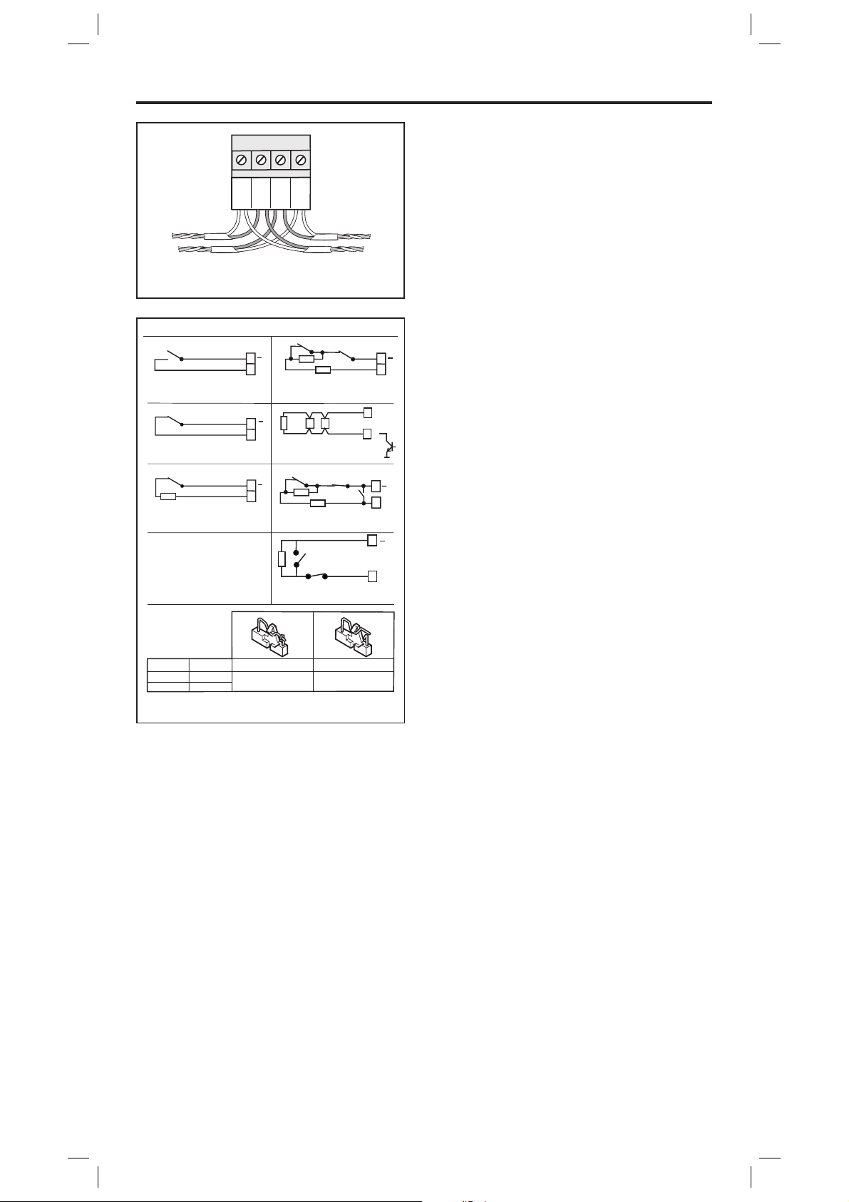
4. Wiring
The terminals are shown in fig. 3 and on the wiring
diagram glued to the inside of the cover.
4.1 E-Bus (fi g. 6)
Cable type 24 AWG 7 x Ø 0,2 mm is recommended.
The to tal length of the E-Bus cable must not exceed
500 m. The E-Bus must be connected to the cen tral
control unit (B1-, B2, B3, B4+). It may be routed in
parallel to other accessories. If shielded cable is used,
all the shields must be connected at one point, e.g. at
an NC terminal.
4.2 Tamper contact
If the SMT 12 circuit board is not fitted in the SAT
12 housing, the plug connector (fig. 3 W) must be
connected to an external tamper contact or be shortcircuited. Use the socket connector provided to connect
Z
to an external tamper con tact.
4.3 Inputs (fi g. 7)
All inputs can be operated in modes 1 to 4 and 6 to
Z
O
7 (fig. 7). Inputs Z1 to Z2 can also be operated with
glass break alarms. To do this, the relevant switches
SW1 to SW2 must be closed and one terminal of each
glass break sensor connected to one of outputs O1 to
O2, which must be programmed for «Latching sensor
reset». When wiring fire detectors, any trou ble out put
present can be looped directly into the line. For fire
Z
detectors where the power has to be disconnected
to reset the alarm, the negative can be connected
via an output which is programmed as a «Latching
sensor reset» output.
The emergency exit has to be wired like mode 6. A
short circuit of the input will reset the corresponding
Z
output.
5. Close and seal the housing
1 - Engage the cover in the retainer at the top (fig. 1).
2 - Close the cover and tighten the retaining screw
(fig. 1).
3 - Use eye (fig. 2 R) for sealing.
6. Technical data
Supply from the E-Bus
Power consumption min. 6 mA
Power consumption max. 19 mA
2 outputs «open collector» 12 V, 150 mA
4 inputs Programmable
Terminating resistors 4.7 kOhm
Operating temperature -10° C to +55° C
Housing ABS
Dimensions in mm, SAT 12 H 86 x W 135 x D
27 Safety class, SAT 12 IP 30
Environmental class, SAT 12 II
Weight, SAT 12 130 g
Dimensions in mm, SMT 12 H 52 x W 91 x D 20
Weight, SMT 12 50 g
The right to make technical changes to the described equipment without
prior notice is reserved.
 Loading...