

Siemens SMG 71 Installation Instructions Manual

s
SMG 71
SLG 71 UK
20 800 650.0-010
Installation instructions
1
p
2
3
o
4
+5
i
-6
B4+
B3
u
B2
B1-
-7
y
+8
t
r
e
w
q
}
{
P
O
I
Fig. 1
8AA11448 - E0 - 11/03/2002 - UK - SNR 811448.0-001
Fig. 2
+9
10
11
12
13
14
15
16
17
18
19
20
21
22
23
24
25
26
A B
S6
2
4
-
3
2
-
1
B4+
1
B3
ST1
B2
S2
S1
S5
B1-
1. Product Description
The Card reader Gateway SMG 71 replaces one standard
Q
S4
S3
W
E
R
transponder (SMT 12) and Mirrors a Keypad with the same
address. 2 cardreaders may be connected for door opening/
closing and setting/unsetting.
2. Supply package
The SMG 71 package contains the following:
- One circuit board SMG 71
- 6 mounting studs
T
Y
- 8 terminating resistors (4.7 kOhm)
- One SLG 71 language kit
3. Mounting Instructions
The SMG 71 is designed for mounting inside a remote power
supply or other suitable box, within a dry room.
It must not be exposed to either dripping or splashing water.
3.1 Product overview (fi g. 1)
- Q Switch for the «auto shunt» function
U
- W Switch for the type of reader
- E Addressing button
- R Thermofuse 12 V; 650 mA
- T Plug connector for external tamper contact
- Y Tamper contact
- U Switch for programming glass breaks alarm inputs
- I Stand alone Input
Embedded Transponder:
- O 4 programmable inputs (1 to 4)
- P Open collector output 2
- { Relay output 1
Open collector outputs with dedicated functions:
- } Auto shunt function running
- q Cannot set
- w Set/Unset
- e Buzzer
Ward status
information of
}
mirrored keypad
- r Alarm in memory
- t Error information
(site code not programmed/parity error/E-Bus failure)
- y 12 V power supply for outputs
- u E-Bus connection
- i 12 V power supply for card reader
- o Connection to card reader 2
- p Connection to card reader 1
Fig. 3
3.2 Fit circuit boards (fi g. 2)
1 - Engage the mounting studs (provided with the circuit
A
B
boards) in the holes provided (A).
2 - Fit circuit boards .
4. Wiring
4.1 E-Bus (fi g. 3)
The E-Bus (A) must be connected to the central control unit (B1-,
B2, B3, B4+). It may be routed in parallel to other accessories
(B). For additional information see the Control panel installation
manual.
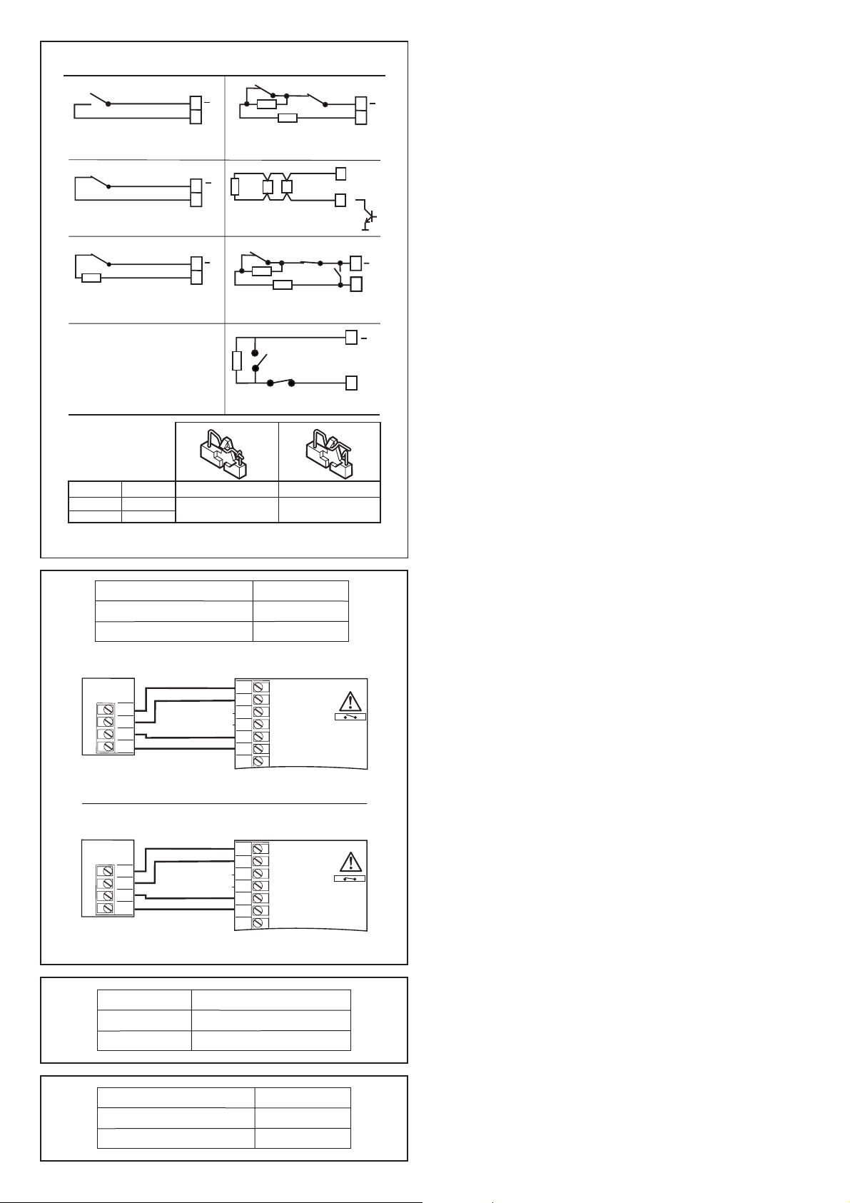
1. Normally open contact
2. Normally closed contact
4k7
3. Normally closed contact
monitored
Z1
Z2
Switches SW 1 and SW 2 must be open.
To connect a maximum
SW 1
of 20 glass break sensor
SW 2
Fig. 4
Type of card reader
Wiegand (26 bits)
ABA track 2 (Data + clock)
Wiegand
Reader 1
D0
D1
+12V
0V
ABA ANSI Track 2
Reader 1
CLK
DATA
+12V
0V
Reader 2
Fig. 5
Card reader 1
On line
Stand alone
Fig. 6
Input modes
Alarm
Z
Z
Z
ClosedInput
Reader 2
CLK
DATA
Stand alone input ( fig. 1)I
Open
Closed (-)
4k7
4. Alarm & tamper monitored
4k7
5. Glass break sensor
Alarm
4k7
6. Emergency exit
Alarm
4k7
7. Fire input
Switch S3
Open
Closed
1
2
3
D0
D1
4
+5
-6
B4+
D0 and D1 can be either
open collectors, 5V or 12 V signals
1
2
3
4
+5
-6
B4+
CLK and Data can be either
open collectors, 5 V or 12 V signals
4k7
Tamper
Reset
4k7
Trouble
OpenSwitch
All other modes
Tamper
SMG 71
SMG 71
Z
O
S3 open
S3 close
4.2 Tamper contact
The Tamper connector (fi g. 1; T) must be connected to an
external tamper contact or be short-circuited.
Z
4.3 Inputs (fi g. 4)
All inputs can be operated in modes 1 to 4 and 6 to 7 (fi g. 4).
Inputs 1 to 2 can also be operated with glass break alarms.
To do this, the relevant switches S1 to S2 must be closed
and one terminal of each glass break detectors connected
to one of outputs 1 or 2, which must be programmed for
«Latching sensor reset». When wiring fi re detectors, any
trouble output present can be looped directly into the line.
For fi re detectors where the power has to be disconnected
to reset the alarm, the negative can be connected via
an output which is programmed as a «Latching sensor
Z
reset» output.
The emergency exit has to be wired like mode 6. A short
circuit of the input will reset the corresponding signalling
output.
4.4 Card reader (fi g. 5)
Z
Two type of card readers (ABA Track 2 / Wiegand ) can be
selected by the switch S3 .
5. Addressing
Since the replaced transponder takes the same address as
the card reader gateway only free transponder addresses
are accepted as gateway addresses.
6. Card reader Test menu
A special menu is available in the Engineer menu to test
the card reader.
The Site code and user number are displayed on the
keypad.
7. Special function
7.1 Stand alone mode (fi g. 6)
In the stand alone mode, a valid card(site code) read by
reader 1 (fi g. 1; p), Will activate the relay output 1(fi g. 1;
{) directly for 5 seconds.
In this mode there is no interaction with the control panel,
the site code is Checked locally in the Gateway.
7.2 Auto-Shunt mode (fi g. 7)
In the auto-shunt mode, an activation of the output 1(fi g. 1; {)
bypasses the Input 1(fi g.1; O) until it is in a quite state again.
The bypass time is max. 40 s after which the Input 1 will
be restored.
If Input 1 is not in a quite state after 30 s the buzzer output
(fi g.1; e) will be activated.
The open collector output «Auto-Shunt function» (fi g.1; })
is activated as long as Input 1 is bypassed.
8. Technical data
Supply 12 VDC from the E-Bus
Power consumption min. 11 mA
Power consumption max. 35 mA
7 open collector outputs 12 V, 150 mA
1 relay output 12 V, 1 A
4 inputs Programmable
8 terminating resistors 4.7 kOhm
Operating temperature -10° C to +55° C
Dimensions in mm, SMG 71 H 54,5 x W 156 x D 20
Weight, SMG 71 65 g
Fig. 7
Auto-Shunt
Off
On
Switch S4
Open
Closed
The right to make technical changes to the described equipment without prior notice
is reserved.
 Loading...